
LE840TT - Stampante OKI - Manuale utente e istruzioni gratuiti
Trova gratuitamente il manuale del dispositivo LE840TT OKI in formato PDF.

| Tipo di prodotto | Stampante per etichette termica |
| Metodo di stampa | Trasferimento termico e termico diretto |
| Risoluzione | 203 dpi (8 punti/mm) |
| Velocità di stampa | Fino a 12 pollici/s (305 mm/s) |
| Larghezza di stampa massima | 104 mm (4.09 pollici) |
| Supporto di stampa | Etichette, tag, carta continua, cartone (vedere raccomandazioni) |
| Sensori | Sensore trasmissivo (gap) e riflessivo (marca nera) regolabili |
| Interfacce standard | USB 2.0, Ethernet (LAN) |
| Interfacce opzionali | RS-232C, Centronics, WLAN, Espansione I/O, RFID |
| Opzioni | Modulo coltello, modulo di distacco, kit RFID HF, scheda RTC/USB Host |
| Funzioni | Calibrazione automatica, regolazione fine posizione, Web Printer, modalità dump, log su memoria USB |
| Alimentazione | 100-240 V CA, 50/60 Hz |
| Consumo elettrico | Circa 100 W (stima) |
| Dimensioni (L x P x A) | 266 x 230 x 170 mm (stima) |
| Peso | Circa 5 kg (stima) |
| Temperatura di funzionamento | Da 0 a 40 °C |
| Umidità di funzionamento | Dal 20 al 90 % senza condensa |
| Manutenzione | Pulizia della testina di stampa, del rullo, dei sensori e del modulo coltello opzionale |
| Sicurezza | Messa a terra, non aprire, precauzioni contro le scosse elettriche, non utilizzare solventi |
| Pezzi di ricambio e riparabilità | Testina di stampa 203 dpi, nastro, ricambi; contattare un rappresentante autorizzato Oki |
| Informazioni generali | Marca OKI, modello LE840TT, manuale disponibile in più lingue |
Domande frequenti - LE840TT OKI
Domande degli utenti su LE840TT OKI
0 domanda su questo apparecchio. Rispondi a quelle che conosci o fai la tua.
Fai una nuova domanda su questo apparecchio
Scarica le istruzioni per il tuo Stampante in formato PDF gratuitamente! Trova il tuo manuale LE840TT - OKI e riprendi in mano il tuo dispositivo elettronico. In questa pagina sono pubblicati tutti i documenti necessari per l'utilizzo del tuo dispositivo. LE840TT del marchio OKI.
MANUALE UTENTE LE840TT OKI
User's Guide
PREFACE
Every effort has been made to ensure that the information in this document is complete, accurate, and up-to-date. The manufacturer assumes no responsibility for the results of errors beyond its control. The manufacturer also cannot guarantee that changes in software and equipment made by other manufacturers and referred to in this manual will not affect the applicability of the information in it. Mention of software products manufactured by other companies does not necessarily constitute endorsement by the manufacturer.
While all reasonable efforts have been made to make this document as accurate and helpful as possible, we make no warranty of any kind, expressed or implied, as to the accuracy or completeness of the information contained herein.
All rights are reserved by Oki Data Corporation. Unauthorized copying, transferring, translating, or related actions are prohibited. You must obtain written permission from Oki Data Corporation before doing any of the above.
© 2012 Oki Data Corporation
OKI is a registered trademark of Oki Electric Industry Co., Ltd.
Energy Star is a trademark of the United States Environmental Protection Agency.
Microsoft, Windows, Windows Server and Windows Vista are registered trademarks of Microsoft Corporation.
Apple, Macintosh, Rosetta, Mac and Mac OS are registered trademarks of Apple Inc.
Other product names and brand names are registered trademarks or trademarks of their proprietors.

As an Energy Star Program Participant, the manufacturer has determined that this product meets the Energy Star guidelines for energy efficiency.

This product complies with the requirements of the Council Directives 2004/108/EC (EMC) and 2006/95/EC (LVD), 1999/5/ EC (R&TTE) and 2011/65/EU(RoHS) as amended where applicable, on the approximation of the laws of the member states relating to Electromagnetic Compatibility, Low Voltage, Radio & Telecommunications Terminal Equipment, Energy related Products and Restriction on the use of certain Hazardous Substances in electrical and electronic equipment.
The following cables were used to evaluate this product to achieve EMC directive 2004/108/EC compliance and configurations other than this may affect that compliance.
| CABLE TYPE | LENGTH (METRE) | CORE | SHIELD |
| Power | 2.0 | × | × |
| USB | 1.5 | × | ✓ |
| Serial | 2.0 | × | ✓ |
| Parallel | 4.0 | × | ✓ |
| LAN | 3.0 | × | × |
WARNING! This is a class A product as defined in EN55022. In a domestic environment this product may cause radio interference, in which case the user may be required to take adequate measures.
MANUFACTURER
Oki Data Corporation,
4-11-22 Shibaura, Minato-ku,
Tokyo 108-8551,
Japan
For all sales, support and general enquiries contact your local distributor.
IMPORTER TO THE EU/AUTHORISED REPRESENTATIVE
OKI Europe Limited (trading as OKI Printing Solutions)
Blays House
Wick Road
Egham
Surrey, TW20 0HJ
United Kingdom
For all sales, support and general enquiries contact your local distributor.
ENVIRONMENTAL INFORMATION

| CE Compliance (for EU only) This product complies with the requirements of EMC and Low Voltage Directives including their amendments. |
| VORSICHT: · Schallemission: unter 70dB (A) nach DIN 45635 (oder ISO 7779) · Die für das Gerät Vorgesehene Steckdose muß in der Höhe des Gerätes und leicht zugänglich sein. |
| Centronics is a registered trademark of Centronics Data Computer Corp. Microsoft is a registered trademark of Microsoft Corporation. Windows is a trademark of Microsoft Corporation. |
| This equipment has been tested and found to comply with the limits for a Class A digital device, pursuant to Part 15 of the FCC Rules. These limits are designed to provide reasonable protection against harmful interference when the equipment is operated in a commercial environment. This equipment generates, uses, and can radiate radio frequency energy and, if not installed and set in accordance with the instruction manual, may cause harmful interference to radio communications. Operations of this equipment in a residential area is likely to cause harmful interference in which case the user will be required to correct the interference at his own expense. (for USA only) |
| Changes or modifications not expressly approved by the manufacturer for compliance could void the user's authority to operate the equipment. |
| “This Class A digital apparatus meets all requirements of the Canadian Interference-Caising Equipment Regulations.” “Cet apparéil numérique de la classe A respecte toutes les exigences du Règlement sur le matériel brouilleur du Canada.”(for CANADA only) |
Precautions for the handling of Wireless Communication Devices
Wireless LAN Module: SD-Link 11g
For Europe
This device was tested and certified by Notified Body.
Hereby, Oki Data Corporation declares that this device is in compliance with the essential requirements and other relevant provisions of Directive 1999/5/EC.
This equipment uses the radio frequency band which has not been standardised throughout the EU and EFTA countries. It can be used in the following countries.
Austria, Belgium, Bulgaria, Cyprus, Czech Republic, Denmark, Estonia, Finland, France, Hungary, Germany, Greece, Ireland, Italy, Latvia, Lithuania, Luxembourg, Malta, Netherlands, Poland, Portugal, Romania, Slovakia, Slovenia, Spain, Sweden, United Kingdom, Norway, Liechtenstein, Iceland, Switzerland
For USA
This device complies with Part 15 of the FCC Rules.
Operation is subject to the following two conditions:
(1) This device may not cause harmful interference, and
(2) This device must accept any interference received, including interference that may cause undesired operation.
Changes or modification not expressly approved by manufacturer for compliance could void the user's authority to operate the equipment.
For Canada
Operation is subject to the following two conditions:
(1) This device may not cause interference, and
(2) This device must accept any interference, including interference that may cause undesired operation of the device.
For safety
Do not operate this product in locations where its use may be prohibited. For example, in an aeroplane or hospital. If you are unsure whether operation is permitted, please refer to and follow the airline company or medical institution guidelines.
Otherwise, flight instrument or medical equipment may be affected, causing a serious accident.
This product may affect the operation of some implanted cardiac pacemakers and other medically implanted equipment. Pacemaker patients should be aware that the use of this product in close proximity to a pacemaker might cause the device to malfunction.
If you have any reason to suspect that interference is taking place, immediately turn off the product and contact your Oki Data sales agent.
Do not disassemble, modify, or repair the product as doing so may cause injury.
Modification is also against the Laws and Regulations for Radio Equipment. Please ask your Oki Data sales agent for repair.
| Safety Summary Personal safety in handling or maintaining the equipment is extremely important. Warnings and Cautions necessary for safe handling are included in this manual. All warnings and cautions contained in this manual should be read and understood before handling or maintaining the equipment. Do not attempt to effect repairs or modifications to this equipment. If a fault occurs that cannot be rectified using the procedures described in this manual, turn off the power, unplug the machine, and then contact your authorised Oki Data representative for assistance. | |||
| Meanings of Each Symbol This symbol indicates warning items (including cautions). Specific warning contents are drawn inside the △symbol. (The symbol on the left indicates a general caution.) This symbol indicates prohibited actions (prohibited items). Specific prohibited contents are drawn inside or near the ⊙symbol. (The symbol on the left indicates “no disassembling”). This symbol indicates actions which must be performed. Specific instructions are drawn inside or near the ●symbol. (The symbol on the left indicates “disconnect the power cord plug from the outlet”). | |||
| WARNING This indicates that there is the risk of death or serious injury if the machine is improperly handled contrary to this indication. | |||
| Use only specified AC voltage. Prohibited | Do not use voltages other than the AC voltage specified on the rating plate, as this may cause fire or electric shock. | Prohibited | Do not plug in or unplug the power cord with wet hands as this may cause electric shock. |
| If the machine shares the same electrical outlet, with any other apppliance that consumes a large amount of power, the voltage will fluctuate widely each time these appliances operate. Be sure to provide an exclusive outlet for the machine as this may cause fire or electric shock. | Prohibited | Do not place metal objects or water-filled containers (flower vases, flower pots or mugs etc) on top of the machine. If metal objects or spilled liquids enter the machine, this may cause fire or electric shock. | |
| Prohibited | Do not insert or drop metal, flammable or other foreign objects into the machine through ventilation slits, as this may cause fire or electric shock. | Prohibited | Do not scratch, damage or modify the power cords. Do not place heavy objects on, pull on, or excessively bend the power cords, as this may cause fire or electrical shock. |
| Disconnect the plug. | If the machine is dropped or the cabinet is damaged, turn off the power switch and disconnect the power cord plug from the outlet, and then contact your authorised Oki Data representative for assistance. Continued use of a damaged machine may cause fire or electric shock. | Disconnect the plug. | Continued use of the machine in an abnormal condition (the machine is producing smoke or a strange smell) may cause fire or electric shock. In these cases, immediately turn off the power switch and disconnect the power cord plug from the outlet. Then, contact your authorised Oki Data representative for assistance. |
| Disconnect the plug. | If foreign objects (metal fragments, water, liquids) enter the machine, turn off the power switch and disconnect the power cord plug from the outlet, and then contact your authorised Oki Data representative for assistance. Continued use of the machine in that condition may cause fire or electric shock. | Disconnect the plug. | When unplugging the power cords, be sure to hold and pull on the plug. Pulling on the cord may cut or expose the internal wires and cause fire or electric shock. |
| Connect a grounding wire. | Ensure that the equipment is properly grounded. Extension cables should also be grounded. Fire or electric shock could occur on improperly grounded equipment. | No disassembling. | Do not remove covers, repair or modify the machine yourself. Contact your Oki Data representative for assistance. You may be injured by high voltage, very hot parts or sharp edges inside the machine. |
| Prohibited | Do not use a spray cleaner containing flammable gas for cleaning this product, as this may cause a fire. | Prohibited | Care must be taken not to injure yourself with the printer paper cutter, projection and the edge of sheet metal. |
| CAUTION This indicates that there is the risk of personal Injury or damage to objects if the machine is improperly handled contrary to this indication. | |||
| Precautions The following precautions will help to ensure that this machine will continue to function correctly. · Try to avoid locations that have the following adverse conditions: * Temperatures out of the specification * Direct sunlight * High humidity * Shared power source * Excessive vibration * Dust/Gas The cover should be cleaned by wiping with a dry cloth or a cloth slightly dampened with a mild detergent solution. NEVER USE THINNER OR ANY OTHER VOLATILE SOLVENT on the plastic covers. USE ONLY Oki Data SPECIFIED paper and ribbons. DO NOT STORE the paper or ribbons where they might be exposed to direct sunlight, high temperatures, high humidity, dust, or gas. Ensure the printer is operated on a level surface. Any data stored in the memory of the printer could be lost during a printer fault. Try to avoid using this equipment on the same power supply as high voltage equipment or equipment likely to cause mains interference. Unplug the machine whenever you are working inside it or cleaning it. Keep your work environment static free. Do not place heavy objects on top of the machine, as these items may become unbalanced and fall causing injury. Do not block the ventilation slits of the machine, as this will cause heat to build up inside the machine and may cause fire. Do not lean against the machine. It may fall on you and could cause injury. Unplug the machine when it is not used for a long period of time. Place the machine on a stable and level surface. Do not turn on the printer power while the ON LINE and ERROR lamp are blinking as this may cause damage to the printer. RISK OF EXPLOSION IF BATTERY IS REPLACED BY AN INCORRECT TYPE. DISPOSE OF USED BATTERIES ACCORDING TO THE INSTRUCTIONS. | |||
| Request Regarding Maintenance · Utilise our maintenance services. After purchasing the machine, contact your authorised Oki Data representative for assistance once a year to have the inside of the machine cleaned. Dust will build up inside the machines and may cause a fire or a malfunction. Cleaning is particularly effective before humid rainy seasons. · Our preventive maintenance service performs periodic checks and other work required to maintain the quality and performance of the machine. For details, please consult your authorised Oki Data representative. · Do not expose the machine to insecticides or other volatile solvents. This may cause the cabinet, or other parts, to deteriorate and may cause the paint to peel. | |||
TABLE OF CONTENTS
Page
1.PRODUCT OVERVIEW E1-1
1.1 Introduction.. E1- 1
1.2 Features E1-1
1.3 Unpacking.. E1- 1
1.4 Accessories E1-2
1.5 Appearance E1-3
1.5.1 Dimensions.. E1-3
1.5.2 Front View .E1-3
1.5.3 Rear View.. E1- 3
1.5.4 Operation Panel E1-4
1.5.5 Interior E1-4
1.6 Options E1-5
2. PRINTER SETUP E2-1
2.1 Installation E2-2
2.2 Connecting the Power Cord E2-3
2.3 Loading Supplies E2-4
2.3.1 Loading the Media.. E2-5
2.3.2 Loading the Ribbon.. E2-10
2.4 Connecting the Cables to Your Printer E2-12
2.5 Turning the Printer ON/OFF E2-13
2.5.1 Turning ON the Printer .E2-13
2.5.2 Turning OFF the Printer.. E2-13
2.6 Printer Setting.. E2-14
2.6.1 User System Mode.. E2-15
2.6.2 Parameter Setting E2-16
2.6.3 Enabling LAN/WLAN E2-24
2.6.4 Basic Program Setting.. E2-24
2.6.5 Enabling Z-Mode E2-25
2.6.6 Automatic Calibration . E2-26
2.6.7 Dump Mode Setting.. E2-27
2.6.8 Logging.. E2-29
2.6.9 System Mode E2-30
2.6.10 Interface Setting . E2-31
2.6.11 Real Time Clock (RTC) E2-38
2.6.12 Copying Data to/from USB Memory .E2-39
2.7 Installing the Printer Drivers E2-41
2.7.1 Introduction.. E2-41
2.7.2 General Description.. E2-41
2.7.3 Installing the Printer Driver.. E2-42
2.7.4 Installation under Windows XP/Server 2003/Vista/ Server 2008/7/Server2008 R2. E2-42
2.7.5 Uninstalling the Printer Driver.. E2-45
2.7.5.1 For Windows 7/Server 2008 R2.. E2-45
2.7.5.2 For Windows Vista/Server 2008 .E2-48
2.7.5.3 Other OS .E2-48
2.8 Print Test E2-49
2.9 Position and Print Tone Fine Adjustment E2-51
2.9.1 Fine Adjustment .E2-51
2.10 Threshold Setting E2-58
2.11 Sensor Setting E2-61
3. ONLINE MODE E3-1
3.1 Key Functions E3-1
3.2 LCD E3-2
3.2 Operation Example E3-3
4. MAINTENANCE E4-1
4.1 Cleaning E4-1
4.1.1 Print Head/Platen/Sensors E4-1
4.1.2 Covers and Panels E4-2
4.1.3 Optional Cutter Module.. E4-3
5. TROUBLESHOOTING E5-1
5.1 Error Messages E5-1
5.2 Possible Problems E5-4
5.3 Removing Jammed Media.. E5- 5
6. PRINTER SPECIFICATIONS E6-1
7. SUPPLY SPECIFICATIONS E7-1
7.1 Media.. E7- 1
7.1.1 Media Type.. E7-1
7.1.2 Detection Area of the Transmissive Sensor (Gap sensor) E7-3
7.1.3 Detection Area of the Reflective Sensor (Black mark sensor) E7-4
7.1.4 Effective Print Area.. E7-5
7.1.5 RFID Tags E7-6
7.2 Ribbon E7-8
7.3 Recommended Media and Ribbon Types E7-10
7.4 Care/Handling of Media and Ribbon E7-16
APPENDIX 1 MESSAGES AND LEDs. EA1-1
APPENDIX 2 INTERFACE . EA2-1
APPENDIX 3 PRINT SAMPLES EA3-1
APPENDIX 4 GLOSSARIES EA4-1
WARNING!
This is a Class A product. In a domestic environment this product may cause radio interference in which case the user may be required to take adequate measures.
CAUTION!
- This manual may not be copied in whole or in part without prior written permission of Oki Data.
- The contents of this manual may be changed without notification.
- Please refer to your local Authorised Service representative with regard to any queries you may have in this manual.
1. PRODUCT OVERVIEW
1.1 Introduction
Thank you for choosing the Oki Data LE840/LE850 series label printer. This User's Guide contains from general set-up through to how to confirm the printer operation using a test print, and should be read carefully to help gain maximum performance and life from your printer. For most queries please refer to this manual and keep it safe for future reference. Please contact your Oki Data representative for further information concerning this manual.
1.2 Features
This printer has the following features:
- The print head block can be opened providing smooth loading of media and ribbon.
- Various types of media can be used as the media sensors can be moved from the centre to the left edge of the media.
- Web based functions such as remote maintenance and other advanced network features are available.
- Superior hardware, including the specially developed 8 dots/mm (203 dots/inch) thermal print head which will allow very clear print at a printing speed of 3, 6, 10, or 12 inches/sec. and 3, 5, 8, 10, or 12 inches/sec. with 11.8 dots/mm (300 dots/inch).
1.3 Unpacking
NOTES:
- Check for damage or scratches on the printer. However, please note that Oki Data shall have no liability for any damage of any kind sustained during transportation of the product.
- Keep the cartons and internal packing for future transportation of the printer.
| LE840 | LE850 |
| 3ips | 3ips |
| 6ips | 5ips |
| 10ips | 8ips |
| 12ips | 10ips |
| 12ips |
- Besides the optional Cutter Module, there is also an optional Strip Module, RS-232C I/F card, Centronics I/F card, Expansion I/O Card, Wireless LAN I/F the RTC/USB host I/F card, HF band RFID mount kit and Narrow width platen kit.
Unpack the printer as per the Unpacking Instructions supplied with the printer.
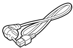
1.4 Accessories
When unpacking the printer, please make sure all the following accessories are supplied with the printer.
Power cord
Safety & Warranty Sheet
Setup Guide
CD-ROM(1pc.)
1.5 Appearance
The names of the parts or units introduced in this section are used in the following chapters.
1.5.1 Dimensions
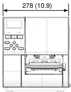
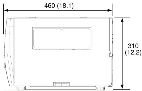
Dimensions in mm (inches)
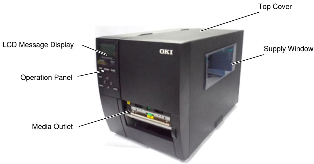
1.5.2 Front View
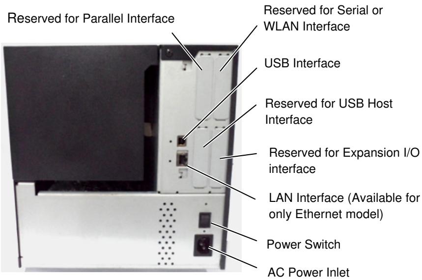
1.5.3 Rear View
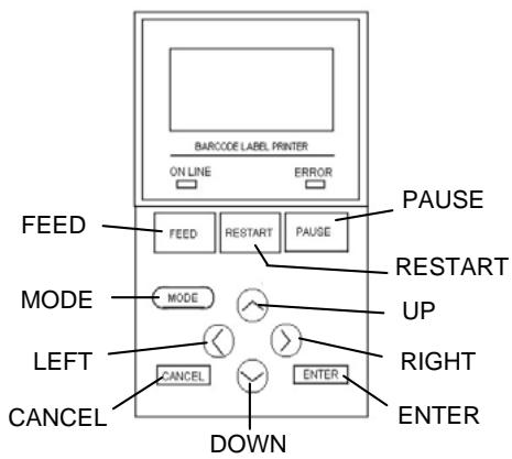
1.5.4 Operation Panel
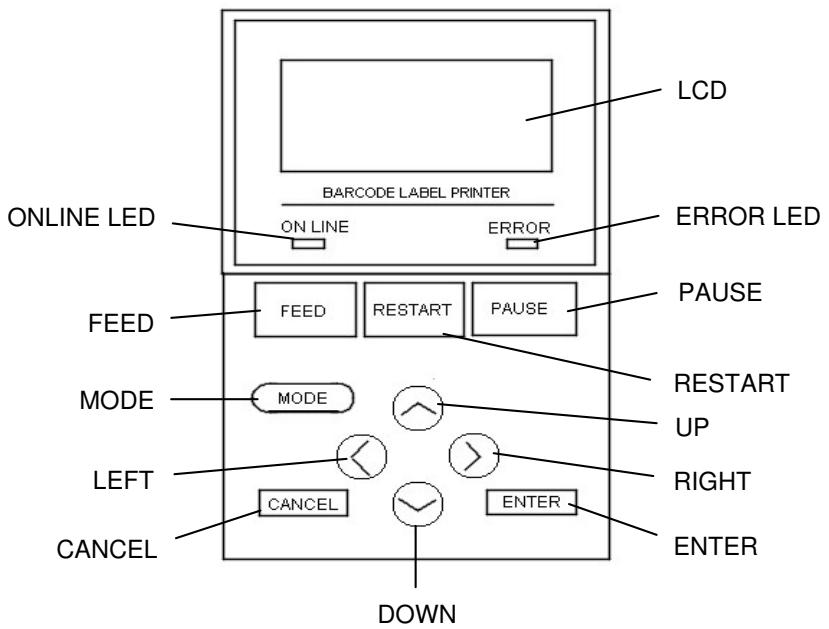
Please see Section 3 for further information about the Operation Panel.
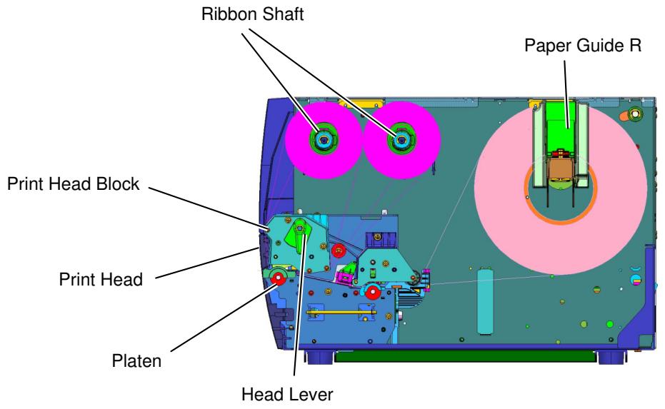
1.5.5 Interior
1.6 Options
| Option Name | Description |
| Cutter module | Each time media is cut, the media feed is stopped. |
| Strip module | This allows use of on-demand (peel-off) operation or to take-up labels and backing paper together when using the rewind guide plate. To purchase the strip module, please inquire with your local distributor. |
| 203-dpi print head | This print head enables a conversion of a 300dpi print head of the LE850 model into 203dpi print head. |
| 300-dpi print head | This print head enables a conversion of a 203dpi print head of the LE840 model into 300dpi print head. |
| RTC & USB host interface card | This card holds the current time: year, month, day, hour, minute, second and provides a USB host interface. |
| Expansion I/O interface card | Installing this card in the printer allows connection to an external device with the exclusive interface. |
| Parallel interface card | Installing this card provides a Centronics interface port. |
| Serial interface card | Installing this card provides an RS-232C interface port. |
| RFID module mount kit | This kit is to mount Tagsys HF band RFID module and antenna. |
| Wireless LAN interface card | Installing this card provides Wireless LAN communication. |
NOTE: To purchase the optional kits, please contact the nearest authorised Oki Data representative or Oki Data Head Quarters.
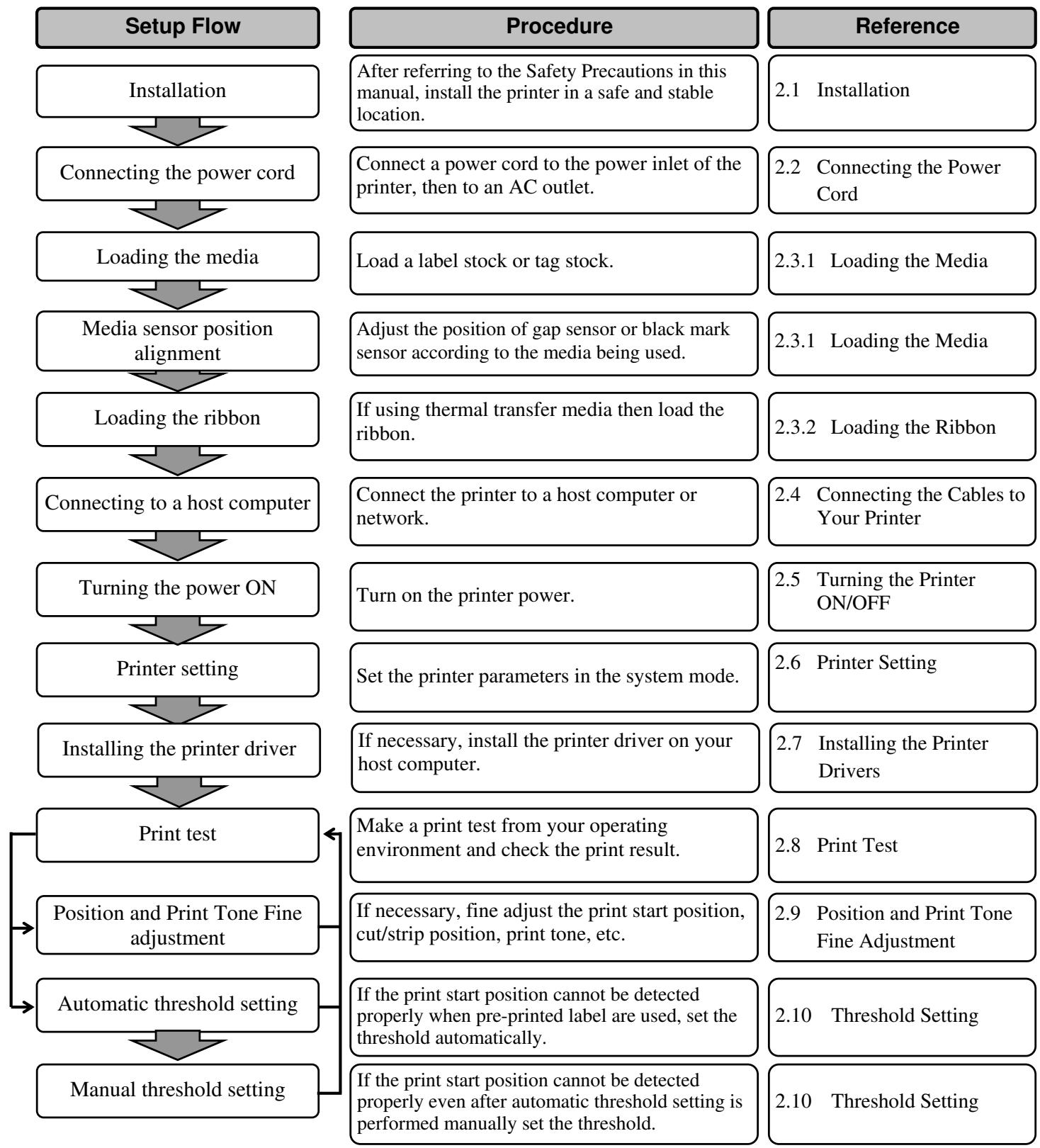
2. PRINTER SETUP
This section outlines the procedures to setup your printer prior to its operation. The section includes precautions, loading media and ribbon, connecting cables, setting the operating environment of the printer and performing an online print test.
2.1 Installation
To insure the best operating environment and to assure the safety of the operator and equipment, please observe the following precautions.
- Operate the printer on a stable, level surface in a location free from excessive humidity, high temperature, dust, vibration and direct sunlight.
- Keep your work environment static free. Static discharge can cause damage to delicate internal components.
- Make sure the printer is connected to a clean source of AC power and no other high-voltage devices, that may cause line noise interference, are connected to the same mains.
Assure that the printer is connected to the AC mains with a three-prong power cable that has the proper ground (earth) connection. - Do not operate the printer with the cover open. Be careful not to allow fingers or articles of clothing to get caught in any of the moving parts, especially the optional cutter mechanism.
- For best results, and longer printer life, use only Oki Data recommended media and ribbons.
- Store the media and ribbons in accordance with their specifications.
- This printer mechanism contains high-voltage components; therefore you should never remove any of the covers of the machine as you may receive an electrical shock. Additionally, the printer contains many delicate components that may be damaged if accessed by unauthorised personnel.
- Clean the outside of the printer with a clean, dry cloth or a clean cloth slightly dampened with a mild detergent solution.
- Use caution when cleaning the thermal print head as it will become very hot while printing. Wait until it has had time to cool before cleaning. Use only the Oki Data recommended print head cleaner to clean the print head.
- Do not turn off the printer power or remove the power plug while the printer is printing or while the ON LINE lamp is flashing.
2.2 Connecting the Power Cord
CAUTION!
- Make sure that the printer Power Switch is turned to the OFF position (O) before connecting the Power Cord to prevent possible electric shock or damage to the printer.
-
Connect the Power Cord to a supply outlet with a properly grounded (earthed) connection.
-
Make sure that the printer Power Switch is in the OFF (O) position. Connect the Power Cord to the printer as shown in the figure below.
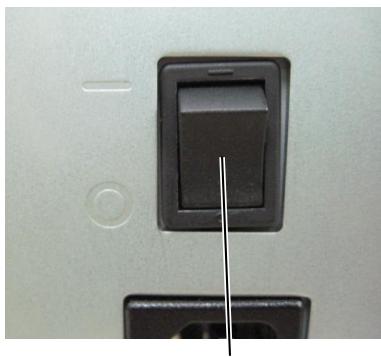
Power Switch
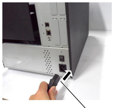
Power Cord
- Plug the other end of the Power Cord into a grounded outlet as shown in the figure below.
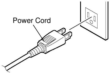
[Example of US Type]
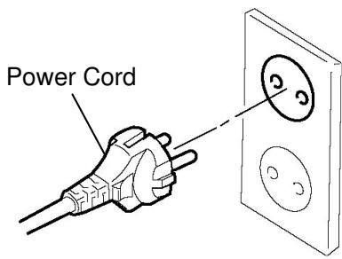
[Example of EU Type]
2.3 Loading Supplies
WARNING!
- Do not touch any moving parts, projection and the edge of sheet metal. To reduce the risk of fingers, jewellery, clothing, etc., being drawn into the moving parts, be sure to load the supplies once the printer has stopped moving completely.
- The Print Head becomes hot immediately after printing, allow it to cool before loading the media.
- To avoid injury, be careful not to trap your fingers while opening or closing the cover.
CAUTION!
- Be careful not to touch the Print Head Elements when lifting the Print Head Block. This may cause missing dots due to static electricity or other print quality problems.
- When loading or replacing the media or ribbon, be careful not to damage the print head with hard objects like watches or rings.
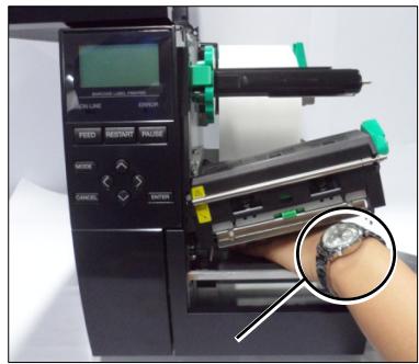
Care must be taken not to allow the metal or glass part of a watch to touch the print head edge.
Care must be taken not to allow a metal object like a ring to touch the print head edge.
Since the print head element can be easily damaged by shock, please treat it carefully and do not hit it with hard objects.
2.3.1 Loading the Media
NOTES:
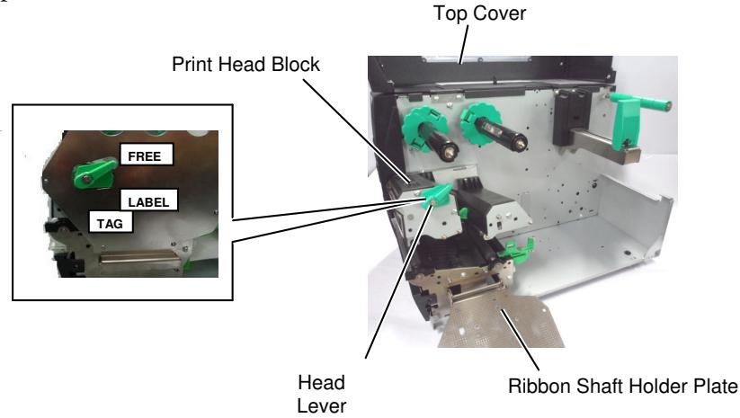
- When the Head Lever is turned to FREE position, the Print Head can be raised.
- To enable printing the Head Lever must be set to the LABEL / TAG position. (This ensures that the Print Head is closed.) There are two head pressure levels in the LABEL / TAG position. Set the Head Lever depending on the media type: Position LABEL: Labels Position TAG: Tags However, proper position may differ depending on media. For details, refer to your Oki Data authorised service representative.
The following procedure shows the steps to properly load the media into the printer so that it feeds straight through the printer.
The printer prints both labels and tags.
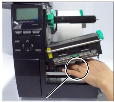
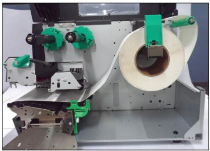
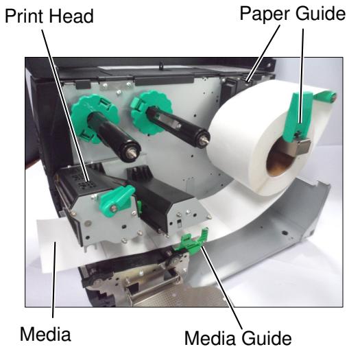
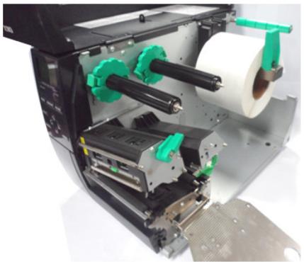
- Open the Top Cover.
- Turn the Head Lever to the FREE position and release the Ribbon Shaft Holder Plate.
- Open the Print Head Block.
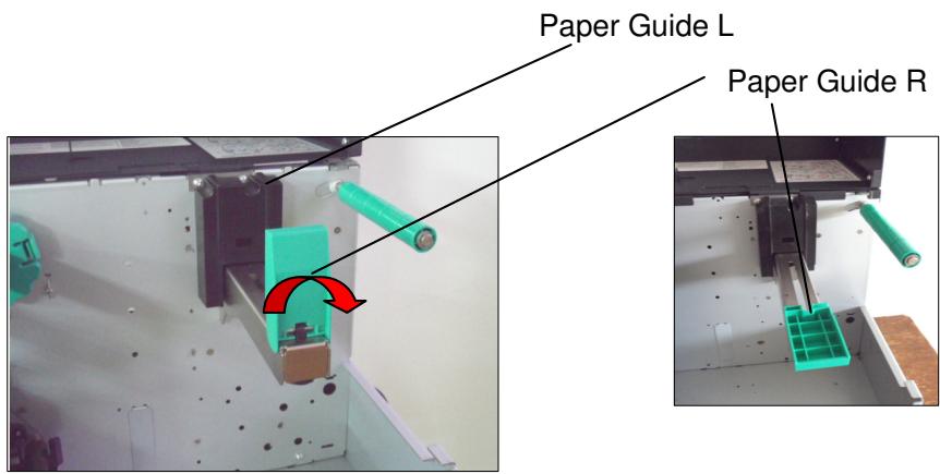
- Move the Paper guide R to the rightmost position or shift the guide to the horizontal position.
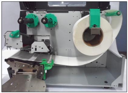
- Put the media on the Paper Holder.
- Pass the media around the Paper Holder, and then pull the media towards the front of the printer.
- Push the Paper Guide against the media until the media is held firmly in place. To lock the Media, shift the Paper Guide R to vertical position
2.3.1 Loading the Media (Cont.)
Do not over-tighten the Locking Ring of the Supply Holder.
In the case of labels rolled with the print side facing inside.
In the case of labels rolled with the print side facing outside.
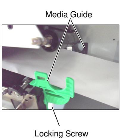
NOTE:
- Place the media between the Media Guides and adjust them to the media width. Once in the correct position tighten the Locking Screw.
- Check that the media's path through the printer is straight. The media should be to the left side of the print head
2.3.1 Loading the Media (Cont.)
- Lower the Print Head Block.
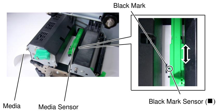
- Once the media is loaded it may be necessary to set the Media Sensors used to detect the start position for label or tag.
Setting the Gap Sensor position
(1) Manually move the Media Sensor so that the Gap Sensor is positioned at the centre of the labels. ( indicates the position of the Gap Sensor).
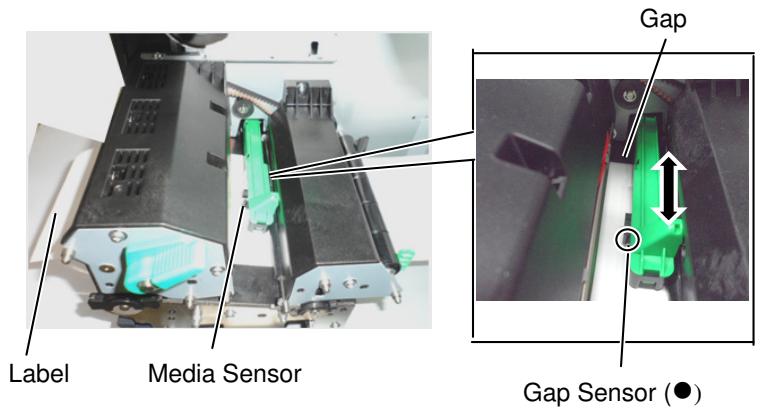
NOTE:
Be sure to set the black mark sensor to detect the centre of the black mark, otherwise a paper jam or no paper error may occur.
Setting the Black Mark Sensor position
(1) Pull about 500mm of media out of the front of the printer, turn the media back on itself and feed it under the Print Head past the sensor so that the black mark can be seen from above.
(2) Manually move the Media Sensor so that the Black Mark Sensor is in line with the centre of the black mark on the media. (■ indicates the position of the Black Mark Sensor).
2.3.1 Loading the Media (Cont.)
12. Batch mode
In batch mode, the media is continuously printed until the number of labels-tags specified in the issue command has been printed.
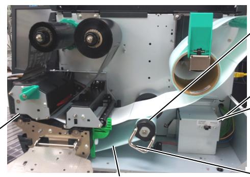
13. Loading with peel off module
When the optional Strip Module is fitted, the label is automatically removed from the backing paper at the Strip Plate as each label is printed.
NOTES:
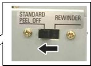
- Be sure to set the Selection Switch to STANDARD/ PEEL OFF position.
- The backing paper is easier to feed back to the Take-Up Spool if the Front Plate is removed.
- Fit the Take-Up Clip so that the longer side of the clip is fitted into the shallow groove in the Take-Up Spool.
- The backing paper can be wound directly onto the Take-up Spool or a paper core.
(1) Remove enough labels from the leading edge of the media to leave 500mm of backing paper free.
(2) Insert the backing paper under the Strip Plate.
(3) Wind the backing paper onto the Take-up Spool and fix it in position with the Take-up Clip. (Wind the paper counter-clockwise around the spool.)
(4) Rotate the Take-up Spool counter-clockwise a few times to remove any slack in the backing paper.
(5) Set the Selection Switch mounted on the Rewinder Assembly to STANDARD/PEEL OFF position.
Strip Plate
Backing Paper
Take-up Spool
Take-up Clip
2.3.1 Loading the Media (Cont.)
WARNING!
The cutter is sharp, so care must be taken not to injure yourself when handling the cutter.
CAUTION!
- Be sure to cut the backing paper of the label. Cutting labels will cause the glue to stick to the cutter which may affect the cutter quality and shorten the cutter life.
-
Use of tag paper when the thickness exceeds the specified value may affect the cutter life.
-
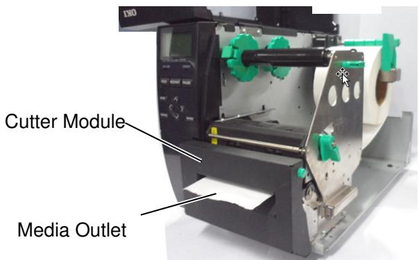
Loading with cutter
When the optional Cutter Module is fitted, the media is automatically cut. A disc cutter is available as option. Insert the leading edge of the media into the cutter until it comes out the Media Outlet of the Cutter Module.
2.3.2 Loading the Ribbon
NOTES:
- When attaching the ribbon stoppers, make sure that the pinchers face into the printer
- Be sure to remove any slack in the ribbon before printing. Printing with a wrinkled ribbon will reduce the print quality.
- The Ribbon Sensor is mounted on the rear of the Print Head Block to detect a ribbon end. When a ribbon end is detected a "NO RIBBON" message will appear on the display and the ERROR LED will illuminate.
There are two types of media available for printing on: thermal transfer and direct thermal (which has a chemically treated surface). DO NOT LOAD a ribbon when using direct thermal media.
- Grasp the tabs on the top and bottom of the Ribbon Stoppers and move the Ribbon Stoppers back to the end of the Ribbon Shaft.
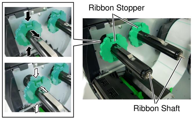
- Leaving plenty of slack between the ribbon spools, place the ribbon onto the Ribbon Shafts as shown below. There are 2 possible ways to load the ribbon.
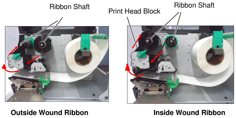
NOTE:
To check or change settings on which type of Ribbon winding to be used, you must go to SYSTEM Mode in the Printer. For more details refer to Key Operation Manual, "8.4.1 PRINTER SET".
2.3.2 Loading the Ribbon (Cont.)
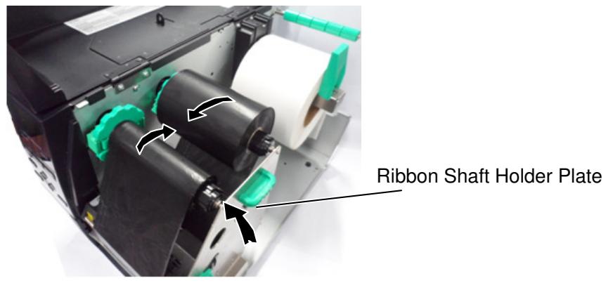
- Push Ribbon along the Ribbon Shafts to a position where the ribbon is fully to the Left against the stoppers when fitted.
- Lower the Print Head Block and set the Ribbon Shaft Holder Plate aligning its holes with the Ribbon Shafts.
- Take up any slack in the ribbon. Wind the leading tape onto the ribbon take-up roll until the ink ribbon can be seen from the front of the printer.
- Turn the Head Lever to Lock position to close the Print Head.
- Close the Top Cover.
2.4 Connecting the Cables to Your Printer
The following paragraphs outline how to connect the cables from the printer to your host computer, and will also show how to make cable connections to other devices. Depending on the application software you use to print labels, there are 5 ways to connect the printer to your host computer. These are:
- An Ethernet connection using the printer's standard LAN connector.
- A USB cable connection between the printer's standard USB connector and your host computer's USB port. (Conforming to USB 2.0)
- A serial cable connection between the printer's optional RS-232 serial connector and one of your host computer's COM ports.
- A parallel cable connection between the printer's optional parallel connector and your host computer's parallel port (LPT).
- Wireless LAN using an optional Wireless LAN board.
For details, refer to APPENDIX 2.
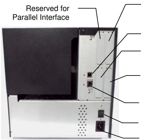
Reserved for Serial or WLAN Interface
USB Interface
Reserved for USB Host interface
Reserved for Expansion I/O Interface
LAN Interface (Available for Ethernet model only) Power Switch
AC Power Inlet
2.5 Turning the Printer ON/OFF
When the printer is connected to your host computer it is good practice to turn the printer ON before turning on your host computer and turn OFF your host computer before turning off the printer.
2.5.1 Turning ON the Printer
CAUTION!
- Use the power switch to turn the printer On/Off. Plugging or unplugging the Power Cord to turn the printer On/Off may cause fire, an electric shock, or damage to the printer.
- Do not turn on the printer power while the ON LINE and ERROR lamp are blinking as this may cause damage to the printer.
NOTE:
If a message other than ON LINE appears on the display or the ERROR LED lamp is illuminated, refer to Section 5.1, Error Messages.
- To turn ON the printer power, press the Power Switch as shown in the diagram below. Note that ( | ) is the power ON side of the switch.
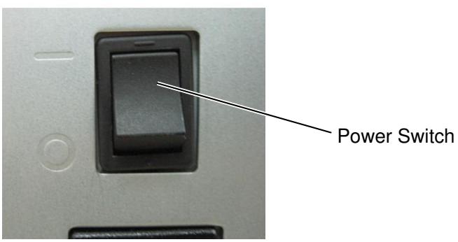
- Check that the ON LINE message appears in the LCD Message Display and that the ON LINE and POWER LED lights are illuminated.
2.5.2 Turning OFF the Printer
CAUTION!
- Do not turn off the printer power while the media is being printed, as this may cause a paper jam or damage to the printer.
-
Do not turn off the printer power while the ON LINE lamp is blinking as this may cause damage to your computer.
-
Before turning off the printer Power Switch verify that the ON LINE message appears in the LCD Message Display and that the ON LINE LED light is on and is not flashing.
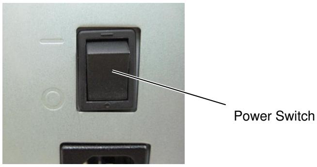
- To turn OFF the printer power press the Power Switch as shown in the diagram below. Note that () is the power OFF side of the switch.
2.6 Printer Setting
Depending on the settings of your host computer or the interface being used it may be necessary to change the printer parameter settings.
Follow the procedures described below to change the printer parameter settings to correspond to your environment.
NOTE:
Incorrect settings can cause the printer not to function correctly. If you have any problems with the parameter settings, please contact your nearest Oki Data service representative.
For the settings this manual does not cover, please contact your nearest Oki Data service representative, or refer to the LE840/LE850 Key Operation Manual.
2.6 Printer Setting (Cont.)
Key functions in system mode
| Key | Function |
| [MODE] | Returns to the system mode menu. |
| [CANCEL] or [FEED]+[RESTART] | Returns to the previous menu. |
| [ENTER] or [PAUSE] | Displays the next screen. |
| Saves the settings and returns to the previous menu. | |
| [UP] or [RESTART] | Moves the cursor up. (Note 1) |
| Increases a value. (Note 2) | |
| [DOWN] or [FEED] | Moves the cursor down. (Note 1) |
| Decreases a value. (Note 3) | |
| [LEFT] | Moves the cursor to the left. (Note 3) |
| [RIGHT] | Moves the cursor to the right. (Note 3) |
NOTES:
- The cursor will not scroll from the bottom to the top or top to bottom of a menu.
- The value will not increase or decrease any further than the maximum or minimum values of a parameter.
- The cursor will not move any further than the left- or right-most positions of a field.
- Any values changed will not become effective if the printer is turned off without pressing the [ENTER] key.
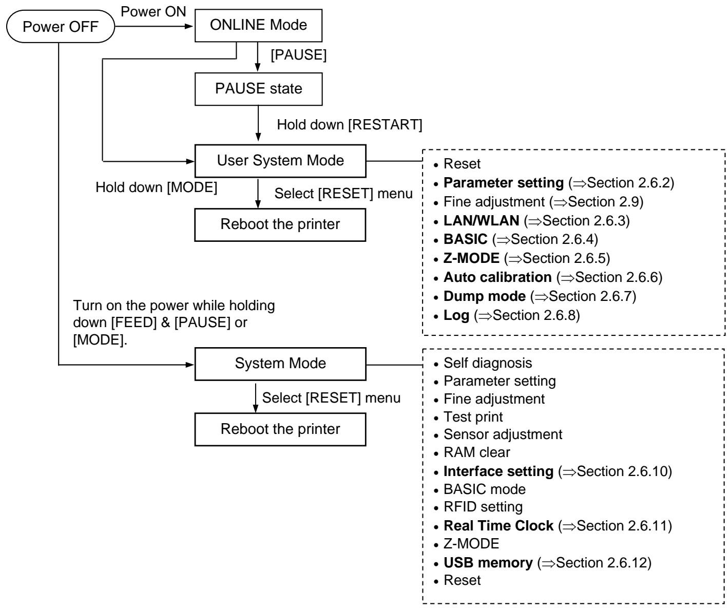
2.6.1 User System Mode
How to enter the User System Mode

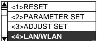
The User System Mode consists of the following menus.
| <1>RESET Used to reboot the printer. |
| <2>PARAMETER SET (⇒ Section 2.6.2) Used to set the printer parameters. |
| <3>ADJUST SET (⇒ Section 2.9) Used to fine adjust the print start position, cut position, etc. |
| <4>LAN/WLAN (⇒ Section 2.6.3) Used to enable or disable the LAN communication and SNMP. |
| <5>BASIC (⇒ Section 2.6.4) Used to set the function of basic program when it is loaded to the printer. |
| <6>Z-MODE (⇒ Section 2.6.5) Same as BASIC |
| <7>AUTO CALIB (⇒ Section 2.6.6) Used to enable or disable the automatic calibration function. |
| <8>DUMP MODE (⇒ Section 2.6.6) Used to print the data in the receive buffer for debugging purposes. |
| <9>LOG (⇒ Section 2.6.7) Used to save print logs in USB memory. |
How to exit the User System Mode
Select <1> RESET menu to reboot the printer.
2.6.2 Parameter Setting
USER SYSTEM MODE
| ▲ | <1>RESET |
| <2>PARAMETER SET | |
| <3>ADJUST SET | |
| <4>LAN/WLAN |
The Parameter Set menu allows the printer parameter settings to be modified.
The following table shows the contents of the Parameter Set menu.
Contents of the Parameter Set Menu
| Menu | Sub menu | Parameter |
| Parameter set | Printer Set (Section 2.6.2.1) | MEDIA LOAD |
| FORWARD WAIT | ||
| FW/BK ACT | ||
| HU CUT/RWD | ||
| RBN SAVE | ||
| PRE PEEL OFF | ||
| BACK SPEED | ||
| TYPE OF RIBBON | ||
| Software Set (Section 2.6.2.2) | FONT CODE | |
| ZERO FONT | ||
| CODE | ||
| PEEL OFF STATUS | ||
| USB I/F STATUS | ||
| FEED KEY | ||
| KANJI CODE | ||
| EURO CODE | ||
| AUTO HD CHK | ||
| WEB PRINTER | ||
| RBN NEAR END | ||
| EX I/O | ||
| LBL/RBN END | ||
| MAX CODE | ||
| XML | ||
| THRESHOLD SELECT | ||
| ENERGY TYPE | ||
| PW SAVE TIME | ||
| RIBBON WIDTH | ||
| Panel (Section 2.6.2.3) | LCD LANGUAGE | |
| DISPLAY | ||
| CONTRAST | ||
| Password (Section 2.6.2.4) | password |
2.6.2 Parameter Setting (Cont.)
NOTE:
Underlined setting is the factory default.
2.6.2.1 Printer Set
(1) MEDIA LOAD
Determines how the use of the [FEED] key enables the printer to detect the home position. This parameter is effective only when the sensor type is set to other than "None".
- OFF Media loading function is disabled (Same as a feed by [FEED] key)
- STD When the [FEED] key is pressed after the printer is tuned on, reset in batch mode, or the print head is closed, the printer detects the next gap/black mark and feeds the paper from the sensor to the print start position.
- ECO When the [FEED] key is pressed after the printer is tuned on, reset in batch mode, or the print head is closed, the printer detects the next gap/black mark and feeds the paper to the print start position based on the last label pitch printed.
- ECO+Bfeed Since optional ribbon saving module is not available to the LE840/LE850, MEDIA LOAD setting and the printer behavior will be automatically changed to "ECO" setting even if "ECO+Bfeed" is selected for these models.
NOTE:
- If the pitch of the media used for the previous issue was less than 20mm, the forward wait will not be activated regardless of the parameter setting.
- The media will stay at the forwarded position even if the power is turned off/on, the printer is reset, the print head is opened/closed.
(2) FORWARD WAIT
This parameter allows you to choose whether or not to activate the auto forward wait function. This function, used in the cut mode, automatically feeds the media forward if there is more than a 1-second idle time after printing. This prevents the top edge of the media from curling.
- OFF Disables the auto forward feed wait
- ON Enables the auto forward feed wait ①
① When ON is selected, the feed amount can be fine adjusted.
(3) FORWARD WAIT POS.
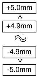
(Default: 0.0mm )
2.6.2 Parameter Setting (Cont.)
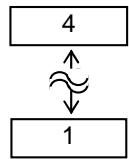
(4) FW/BK ACT.
MODE1
The printer waits for next issue after 13.7-mm media has been fed forward.
- MODE2
When thermal transfer and cut mode are selected, the printer feeds 6-mm media backward, then waits for next issue after 3-mm media has been fed forward.
From this position, the printer starts the on-the-fly printing for next issue. The 3-mm distance to the home position is fed at 3 ips.
NOTE:
Pre-strip function is automatically enabled when the print speed is set to 10 ips or faster. However, the print speed is corrected depending on the EX I/O parameter setting, as follows.
EX I/O: TYPE 1
10 ips (203 dpi)
8 ips (300 dpi)
EX I/O: TYPE 2
Specified speed
(5) HU CUT/RWD
Setting for using the Rewinder in the batch or strip issue modes.
OFF
Rewinder is not used.
ON
Rewinder is used.
(6) RBN SAVE
RIBBON save, Head up related parameter are included in system menu.
However, these function will not be supported by LE840/LE850. Therefore these parameter setting will be ignored and no effect.
(7) PRE PEEL OFF
Select whether to activate the pre-strip function. When this parameter is set to ON, the top edge of a label is separated (pre-stripped) from the backing paper before the label is printed. This function is intended to make the strip issue easier in the case of labels that are hard to strip due to the label density, strength of the adhesive used, or the print speed.
OFF
Disables pre peel off
ON
Enables pre peel off
(8) BACK SPEED
Select back feed speed.
In strip issue a back feed speed of 3 ips may cause the correct distance not to be fed due to a lack of torque, slippery media surface, etc. In such cases reduce the back feed speed to 2 ips to ensure the correct feed amount.
- STD
3ips
- LOW
2ips
(9) TYPE OF RIBBON
Select type of ribbon.
When a coating side of the ribbon is the outside, chooses CSO.
When a coating side of the ribbon is the inside, chooses CSI.
CSO
Coated side out
CSI
Coated side in
2.6.2 Parameter Setting (Cont.)
2.6.2.2 Software Set
(1) FONT CODE
Allows you to select the character code used for printing. Printed characters differ depending on the chosen character code and font.
PC-850
PC-852
PC-857
PC-8
PC-851
PC-855
PC-1250
PC-1251
PC-1252
PC-1253
PC-1254
PC-1257
- LATIN9
Arabic
PC-866
- UTF-8
NOTE:
The following fonts do not support a zero with a slash.
(If a zero with a slash is specified, a zero without a slash will be printed.)
[Bit map fonts]
OCR-A, OCR-B, GOTHIC725 Black, Kanji, Chinese character
[Outline fonts]
Price fonts 1, 2, and 3, DUTCH801
Bold, BRUSH738 Regular, GOTHIC725 Black, TrueType font
(2) ZERO FONT
Allows you to select the way the zero character is printed. Select between "0" and "0".
0
No slash used
0
Slash used
(3) CODE
Select the command control code to be used.
AUTO
Automatically selected.
{,}
- ESC, LF, NUL
- MANUAL
The control code is specified by the user. ①
① When MANUAL is selected, you need to specify each of the control codes 1 to 3 with a hex. code.

2.6.2 Parameter Setting (Cont.)
(4) PEEL OFF STATUS
Specifies whether the printer sends a strip wait status to the host in response to a status request command.
OFF
ON
(5) USB I/F STATUS
Specifies whether to return a response to the host via USB.
OFF
Disables sending a response via USB
ON
Enables sending a response via USB
(6) FEED KEY
Selects the function of the FEED key.
FEED
Feeds one label.
Prints the data in the image buffer (The last label printed)
(7) KANJI CODE
Select the KANJI code.
- TYPE1
Windows code
- TYPE2
Original code
(8) EURO CODE
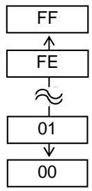
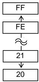
Specifies the Euro code (€).
"20" to "FF" (Specify the hex code in 2 bytes of ASCII code)
(9) AUTO HD CHK
Select whether to perform the auto print head check when the printer is powered on.
OFF
Auto print head check is not performed.
ON
Auto print head check is performed.
2.6.2 Parameter Setting (Cont.)
(10) WEB PRINTER
Select whether to use the printer as a web printer.
When the web printer is enabled, the status of the printer connected to a network can be monitored through the web browser.
- OFF Disables web printer function
- ON INTERNAL Enables web printer function (using internal memory)
- ON EXTERNAL Enables web printer function (using an external usb memory)
NOTE:
Since detecting the remaining ribbon length has a margin of error, use the specified length as a guide.
(11) RBN NEAR END
Select the remaining ribbon length when the ribbon near end is detected.
OFF Ribbon near end is not detected.
- 30m Ribbon near end is detected when the remaining ribbon is 30-m long. (Equivalent to ribbon diameter of 38~mm )
- 70m Ribbon near end is detected when the remaining ribbon is 70-m long. (Equivalent to ribbon diameter of 43~mm )
(12) EX.I/O
Select the type of expansion I/O interface operating mode. This parameter needs to be set depending on the expansion I/O control specification of the device to be connected via the expansion I/O interface.
- TYPE1 Standard mode
- TYPE2 In-line mode
(13) LBL/RBN END
Select the operation to be performed when a label end or ribbon end is detected.
- TYPE1 When a label/ribbon end is detected in the middle of printing, the printer immediately stops printing.
- TYPE2 Selectable only when the ribbon saving function is not activated.
When a label/ribbon end is detected in the middle of printing, the printer prints the half-finished label as far as possible, and stops when the next label is at the home position.
NOTE:
The type specified by the command may differ from the actual mode, depending on the status of this parameter. Also, the data transmission method is slightly different. For details, refer to the External Equipment Interface Manual.
(14) MAXI CODE
Select the Maxicode specification.
- TYPE1 Compatible with the current version
- TYPE2 Special specification
2.6.2 Parameter Setting (Cont.)
(15) XML
Select the type of XML data to be printed.
- OFF Enables XML data printing.
- STD Standard specification
ORACLE Oracle
SAP SAP - STD EXT Standard specification (External memory)
- ORACLE EXT Oracle using an external memory
- SAP EXT SAP using an external memory
(16) THRESHOLD SELECT
This parameter is to choose which threshold value for the media sensor to validate.
- REFLECT Reflective sensor (Black mark sensor)
- TRANS. Transmissive sensor (Gap sensor)
Then, choose which value to use.
- MANUAL SET Threshold set in the Threshold mode takes effect.
- COMMAND SET Threshold set by command takes effect.
(17) ENERGY TYPE
This parameter is intended to make the printer perform appropriate printing for the supplies to be used. If you use a different supply from the setting, poor printing may occur.
- TRANSFER Thermal transfer print method ①
- DIRECT Thermal direct print method ②
① When TRANSFER is selected for the Energy type parameter, choose a ribbon type.
Wax1 Wax 1
Wax2 Wax 2
Wax3 Wax 3
- Semi resin1 Semi-resin 1
- Semi resin2 Semi-resin 2
- Semi resin3 Semi-resin 3
Resin1 Resin 1
Resin2 Resin 2
- Reserve1 to Reserve2 Reserved
② When DIRECT is selected for the Energy type parameter
Standard Standard
- Reserve1 to Reserve9 Reserved
2.6.2 Parameter Setting (Cont.)
NOTE:
For details of the power saving mode, refer to Section 3.4 Power Save Function.
(18) PW SAVE TIME
Sets the length of time until the printer enters the power saving mode. (Unit: minute)
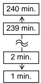
(Default: 15 minutes)
(19) RIBBON WIDTH
Sets the range of the adjustment control depending on the type of ribbon to be used.
- TYPE 1 Narrow range of adjustment control
- TYPE 2 Wide range of adjustment control.
Selection of RBN ADJ.
NOTE:
- The language displayed on panel is Japanese when Japanese is selected, and English when English, German, French, Dutch, Spanish, Italian, Portuguese, Simp. Chinese or Korean is selected.
2.6.2.3 PANEL
(1) LCD LANGUAGE
Choose a language in which the LCD messages are displayed.
- ENGLISH
GERMAN - FRANCH
DUTCH - SPANISH
JAPANESE
ITALIAN - PORTUGUESE
- SIMP. CHINESE
KOREAN
(2) DISPLAY
Choose whether the model name, the number of labels printed and the IP address are displayed or hidden.
- MACHINE NAME
OFF: Hidden
ON: Displayed
- PRINT PAGE
OFF: Hidden
ON: Displayed
- IP ADDRESS
OFF: Hidden
ON: Displayed
2.6.2 Parameter Setting (Cont.)
(3) CONTRAST
Adjust the contrast of the LCD.
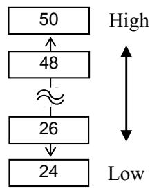
(Default: 40)
2.6.2.4 PASSWORD
(1) PASSWORD
This parameter is for the system administrator only. Please do not change the setting for this parameter.
2.6.3 Enabling LAN/WLAN
USER SYSTEM MODE
The LAN/WLAN menu allows selecting whether or not to enable the LAN communication and SNMP.
(1) LAN/WLAN
- OFF LAN and Wireless LAN are disabled.
ON (AUTO) Automatically selected.
ON (LAN) LAN is enabled.
ON (WLAN) Wireless LAN is enabled.
(2) SNMP
OFF SNMP is disabled.
ON SNMP is enabled.
2.6.4 Basic Program Setting
USER SYSTEM MODE
| <2>PARAMETER SET |
| <3>ADJUST SET |
| <4>LAN/WLAN |
| <5>BASIC |
The following table shows the contents of the Basic program setting menu.
Contents of the Basic Program Setting Menu
| Menu | Sub menu |
| BASIC | BASIC |
| FILE MAINTENANCE | |
| TRACE | |
| EXPAND MODE |
(1) BASIC
Select whether to enable the BASIC program.
OFF
Disables BASIC program.
ON
Enables BASIC program.
(2) FILE MAINTENANCE
The block number and BASIC program file name (up to 12 characters) stored in the BASIC program storage area are displayed. If the file name exceeds 12 characters, the overflowing characters are not displayed.
When no file is stored, a hyphen (“-”) is displayed in place of the file name.
(3)TRACE
Allows you to enable tracing in the BASIC program.
OFF
Disables tracing the BASIC program.
ON
Enables tracing the BASIC program.
(4) EXPAND MODE
The printer switches the mode to execute the BASIC program.
2.6.5 Enabling Z-Mode
USER SYSTEM MODE
| ▲ | <3>ADJUST SET |
| <4>LAN/WLAN | |
| <5>BASIC | |
| <6>Z-MODE |
The Z-Mode menu allows you to select whether or not to enable the Z-Mode.
(1) Z-MODE
OFF
Z-Mode is disabled.
ON SETTING OFF
Z-Mode is enabled. BASIC system mode program is not started automatically.
ON SETTING ON
Z-Mode is enabled. BASIC system mode program is started automatically.
2.6.6 Automatic Calibration
USER SYSTEM MODE
| ▲ | <4>LAN/WLAN |
| <5>BASIC | |
| <6>Z-MODE | |
| <7>AUTO CALIB |
NOTE:
- Since the head-up function is not provided to the LE840/LE850, the setting and the printer behavior will be automatically changed to "ON TRANS", "ON REFLECT", "ON ALL" even if "+"Bfeed" is selected for these models.
The Auto Calibration menu allows you to select whether or not to enable automatic calibration at power on time. When automatic calibration is activated, the printer feeds the media for about 160mm each time the power is turned on or the print head is open then closed to detect the print start position.
(1) AUTO CALIB
OFF
ON TRANS.
ON REFLECT
ONALL
Disabled.
Enabled.-Transmissive sensor (Gap sensor)
Enabled.- Reflective sensor (Black mark sensor)
Enabled. (Transmissive & Reflective sensors)
ON TRANS.+Bfeed
ON REFLECT+Bfeed
ON ALL+Bfeed
same as "ON TRANS" setting
same as "ON REFLECT" setting
same as "ON ALL" setting
NOTES:
- When AUTO CALIB is enabled, an automatic calibration is performed at an open/close of the print head and at a power on time.
- After the automatic calibration is performed, the media length, effective print length, sensor type and whether the ribbon is used or not, obtained through the calibration, will take effect until next calibration is performed or the printer power is turned off. (Settings specified by commands are ignored.)
- This function is available only when the media pitch is 10.0 mm to 150.0 mm .
- When the printer cannot detect the second black mark/gap, it will continue to feed the media for up to 500.0mm. If a black mark/gap is still not detected, the printer will stop, resulting in a paper jam.
- During an automatic calibration, the printer also feeds the ribbon. Even if the ribbon is not loaded, this will not result in an error. However, the print condition will be automatically changed to "No ribbon" after the calibration ends.
- When the cutter is installed and a previous issue was performed in cut issue mode, the media is cut and ejected after the automatic calibration is completed.
- When a label end occurs during an automatic calibration, the printer stops, resulting in an error. Loading new media and closing the print head can clear the error and resume the automatic calibration.
- Since the optional ribbon saving module is not available for the LE840/LE850, Setting + Bfeed will have no effect and the setting will revert to without BFeed.
- The feed speed during automatic calibration is 3 ips.
- Do not open the print head during automatic calibration. The subsequent printer operation is not guaranteed. If you open the print head, turn off the power and back to on.
2.6.7 Dump Mode Setting
USER SYSTEM MODE
| <5>BASIC |
| <6>Z-MODE |
| <7>AUTO CALIB |
| <8>DUMP MODE |
In Dump Mode, the data in the receive buffer is printed. The data is expressed in hexadecimal values. This operation allows verification of the programming commands or the debug of the program.
(1) BUFFER
Select the receive buffer to dump.
- RS-232C
RS-232C receive buffer
CENTRONICS
Centronics receive buffer
- LAN
Network I/F receive buffer
BASIC1
BASIC Interpreter:
I / F Interpreter buffer
- BASIC2
BASIC Interpreter:
Interpreter buffer I/F
USB
USB receive buffer
RFID
RFID receive buffer
NOTES:
- If a file with the same name already exists in the USB memory, it will be overwritten.
- Selecting "RS-232C" or "CENTRONICS" without the optional board installed causes a 0-KB file to be output.
- If an error occurs while using the USB memory, the error message is displayed. For details, refer to Section 2.6.12 Copying Data to/from USB Memory.
(2) DUMP LIST
This parameter is to choose the output destination.
- USB MEMORY
Saves in the USB memory. ① - PRINT
Prints out ②
① When USB MEMORY is selected:
A file is automatically created in the USB memory and named in the following format based on the printer model and saved date.
/ATA0/DUMP/LE840_DUMP_1209271030.DAT / (e.g. LE840(203dpi model), 10:30, Sep 27, 2012)
② When PRINT is selected:
Choose a printing method.
ON DEMAND
Prints 166 lines of data (approx. 50~cm ), then stops. Subsequent data is printed when the [ENTER] key is pressed.
- ALL
Prints all data in the receive buffer.
2.6.7 Dump Mode Setting (Cont.)
Print Conditions
- Printing width: 3.9 inches (Approx. 100mm )
- Sensor selection: None
- Print speed: 6"/sec. (203 dpi) 5"/sec. (300 dpi)
- Printing mode: Depends on the selection in use.
16 bytes/line - Data is printed in the order from the new one to the old.
- Data specified by the receive buffer write pointer will be printed in boldface.
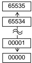
The data in the receive buffer is printed as follows.
| 00 00 00 00 00 00 00 00 00 00 00 00 00 00 00 00 00 00 00 00 00 00 00 00 00 00 00 00 00 00 00 00 00 00 13 | ...... |
| 00 00 00 00 00 00 00 00 00 00 00 00 00 00 00 00 00 00 00 00 00 00 00 00 00 00 00 00 00 00 00 00 00 | ...... |
| 00 00 00 00 00 00 00 00 00 00 00 00 00 00 00 00 00 00 00 00 00 00 00 00 00 00 00 00 00 00 00 01 | ...... |
| 7B 41 58 3B 2B 30 30 30 2C 2B 30 30 30 2C 2B 30 | {AX;+000,+000,+0} |
| 30 7C 7D 7B 44 30 37 37 30 2C 31 31 30 30 2C 30 | 0}|{D0760,1100,0} |
| 37 34 30 7C 7D 7B 43 7C 7D 7B 4C 43 3B 30 30 33 | 740}|{C}|{LC;003} |
| 30 2C 30 30 32 30 2C 30 30 33 30 2C 30 36 36 30 | 0,0020,0030,0660 |
| 2C 30 2C 32 7C 7D 7B 4C 43 3B 30 30 37 30 2C 30 | 0,2}|{LC;0070,0} |
| 30 32 30 2C 30 30 37 30 2C 30 36 36 30 2C 30 2C | 020,0070,0660,0, |
| 39 7C 7D 7B 4C 43 3B 30 30 35 30 2C 30 30 32 30 | 9}|{LC;0050,0020} |
| 44 45 46 47 48 49 4A 7C 7D 7B 50 43 31 30 3B 30 | DEFGHIJ}|{PC10;0} |
| 33 35 30 2C 30 34 30 30 2C 31 2C 31 2C 4B 2C 30 | 350,0400,1,1,K,0} |
| 30 2C 42 3D 41 42 43 44 65 66 67 68 69 6A 6B 6C | 0,B=ABCDefghijkl} |
| 6D 6E 6F 70 7C 7D 7B 50 56 30 32 3B 30 33 33 30 | mnp|}{PV02;0330} |
| 2C 30 36 36 30 2C 30 32 37 30 2C 30 32 35 30 2C | 0660,0270,0250, |
| 41 2C 30 30 2C 42 3D 42 7C 7D 7B 50 56 30 33 3B | A,00,B=B}|{PV03;} |
| ... | ... |
| ... | ... |
| 3B 30 39 30 30 2C 30 31 38 30 2C 54 2C 48 2C 30 | ;0900,0180,T,H,0 |
| 35 2C 41 2C 30 3D 31 32 33 34 35 36 37 38 39 30 | 5,A,0=1234567890 |
| 41 42 43 44 45 7C 7D 00 00 00 00 00 00 00 00 | ABCDE|}....... |
| ... | ... |
| ... | ... |
NOTE:
If an error occurs while printing, the printer stops printing and shows an error message. To clear the error, press the [PAUSE].
After clearing the error the printer does not resume printing automatically.
Receive Buffer Size
| Interface | Size |
| RS-232C | 1MB (65536 lines) |
| Centronics | 1MB (65536 lines) |
| LAN | 1MB (65536 lines) |
| BASIC 1 | 8KB (512 lines) |
| BASIC 2 | 8KB (512 lines) |
| USB | 1MB (65536 lines) |
| RFID | 8KB (512 lines) |
Required Media Length
| Interface | Length |
| RS-232C | 198.2 m |
| Centronics | 198.2 m |
| LAN | 198.2 m |
| BASIC 1 | 2 m |
| BASIC 2 | 2 m |
| USB | 198.2 m |
| RFID | 2 m |
*: Media length required for printing all data in the receive buffer.
2.6.8 Logging
USER SYSTEM MODE
| ▲ | <6>Z-MODE |
| <7>AUTO CALIB | |
| <8>DUMP MODE | |
| <9>LOG |
NOTES:
- If a file with the same name already exists in the USB memory, it will be overwritten.
- If an error occurs while using the USB memory, the error message is displayed. For details, refer to Section 2.6.12 Copying Data to/from USB Memory. After clearing the error the printer does not resume logging automatically.
The Log menu allows the saving of print logs to USB memory.
(1)LOG
- PRINTER TO USB Saves print logs in the USB memory.
A file is automatically created in the USB memory and named in the following format based on the printer model and saved date.
/ATA0/LOG/LE840_LOG_1209271030.DAT
(e.g. LE840(203dpi model), 10:30, Sep 27, 2012)
2.6.9 System Mode
How to enter the System Mode
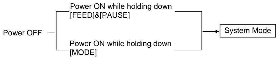
The System Mode consists of the following menus.
| <1>DIAG. Used to check and print the printer system information and maintenance counter status. |
| <2>PARAMETER SET (⇒ Section 2.6.2) Used to set the parameters for each printer function. |
| <3>ADJUST SET (⇒ Section 2.9) Used to fine adjust the print position, cut position, print tone, etc. |
| <4>TEST PRINT Used to perform print tests. |
| <5>SENSOR ADJUST Used to check the sensor statuses and set each sensor. |
| <6>RAM CLEAR Used to perform a RAM clear. DO NOT USE this menu. |
| <7>INTERFACE (⇒ Section 2.6.10) Used to set the interface parameters. |
| <8>BASIC (⇒ Section 2.6.4) Used to set the function of basic program when it is loaded to the printer. |
| <9>FOR FACTORY Used for an in-process inspection. DO NOT use this menu. |
| <10>RFID Used to set RFID related parameters. (see Installation Manual in each RFID kit) |
| <11>RTC (⇒ Section 2.6.11) Used to set the date and time of the real time clock, enable or disable the low battery check, and choose a real time renewal timing. |
| <12>Z-MODE (⇒ Section 2.6.5) Same as BASIC |
| <13>USB MEMORY (⇒ Section 2.6.12) Used to copy data to/from USB memory. |
| <14>RESET Used to reboot the printer. |
How to exit the User System Mode
Select < 14> RESET menu to reboot the printer.
2.6.10 Interface Setting
SYSTEM MODE
| <4>TEST PRINT |
| <5>SENSOR ADJUST |
| <6>RAM CLEAR |
| <7>INTERFACE |
The Interface menu allows configuring printer interface parameters. The following table shows the contents of the Interface menu.
Contents of the Interface Menu
| Menu | Sub menu | Parameter |
| Interface | NETWORK | LAN/WLAN |
| SNMP | ||
| SETTING | ||
| BASIC INFORMATION | ||
| IP ADDRESS | ||
| GATEWAY ADDRESS | ||
| SUBNET MASK | ||
| SOCKET PORT | ||
| PORT NUMBER | ||
| DHCP | ||
| DHCP CLIENT ID | ||
| DHCP HOST NAME | ||
| WLAN STANDARD | ||
| WLAN MODE | ||
| DEFAULT KEY | ||
| 802.11B CHANNEL | ||
| 802.11B BAUD | ||
| 802.11G CHANNEL | ||
| 802.11G BAUD | ||
| WINS | ||
| WINS ADDRESS | ||
| LPR | ||
| USB | ||
| RS-232C | SPEED | |
| DATA LENGTH | ||
| STOP BIT | ||
| PARITY | ||
| CONTROL | ||
| CENTRO. | ACK/BUSY | |
| INPU PRIME | ||
| PLUG & PLAY |
2.6.10 Interface Setting (Cont.)
2.6.10.1 Network Setting
(1) LAN/WLAN
- OFF LAN and Wireless LAN are disabled.
ON (AUTO) Automatically selected.
ON (LAN) LAN is enabled.
ON (WLAN) Wireless LAN is enabled.
(2) SNMP
OFF SNMP is disabled.
ON SNMP is enabled.
(3) BASIC INFORMATION
The following information is displayed.
IP Address
Gateway address
Subnet mask
Socket port status
Socket port number
(4) IP ADDRESS
Set the IP address.

(5) GATEWAY ADDRESS
Set the gateway address.

(6) SUBNET MASK
Set the subnet mask.

(7) SOCKET PORT
Select whether to enable or disable the socket port.
- OFF Socket port is disabled.
- ON Socket port is enabled.
2.6.10 Interface Setting (Cont.)
(8) PORT NUMBER
Set the port number.
(9) DHCP
Select whether to enable/disable DHCP.
OFF ON
DHCP is disabled.
DHCP is enabled.
(10) DHCP CLIENT ID
Select ASCII or HEX for setting DHCP Client ID.
ASCII
DHCP client ID is entered with ASCII code. ①
HEX
DHCP client ID is entered with Hex. code. ②
① When ASCII is selected: Enter 64 characters with ASCII code.
② When HEX is selected: Enter 64 characters with Hex. code.
(11) DHCP HOST NAME
Enter 32 characters with ASCII code.
(12) WLAN STANDARD
11b/g
11b
11g
2.6.10 Interface Setting (Cont.)
(13) WLAN MODE
Set the connection mode and authentication in reference to the following table.
| ADHOC | OFF | |||
| WEP40 | ||||
| WEP104 | ||||
| INFRA | OPEN | OFF | ||
| WEP40 | ||||
| WEP104 | ||||
| SHARED | WEP40 | |||
| WEP104 | ||||
| 802.1x | OPEN SYSTEM | TLS | WEP40 | |
| WEP104 | ||||
| TTLS | WEP40 | |||
| WEP104 | ||||
| LEAP | WEP40 | |||
| WEP104 | ||||
| PEAP | WEP40 | |||
| WEP104 | ||||
| MD5 | WEP40 | |||
| WEP104 | ||||
| EAP-FAST | WEP40 | |||
| WEP104 | ||||
| SHARED KEY | WEP40 | |||
| WEP104 | ||||
| NETWORK EAP | WEP40 | |||
| WEP104 | ||||
| WPA | OPEN | TLS | ||
| TTLS | ||||
| LEAP | ||||
| PEAP | ||||
| EAP-FAST | ||||
| NETWORK EAP | ||||
| WPA-PSK | ||||
| WPA2 | OPEN SYSTEM | TLS | ||
| TTLS | ||||
| LEAP | ||||
| PEAP | ||||
| EAP-FAST | ||||
| NETWORK EAP | ||||
| WPA2-PSK | ||||
2.6.10 Interface Setting (Cont.)
(14) DEFAULT KEY
Select a WEP key.
(Default: 1)
(15) 802.11b CHANNEL
Select a channel for 802.11b WLAN.
(Default:1)
(16) 802.11b BAUD
Select a baud rate for 802.11b WLAN.
11M
- 5.5M
2M
1M
(17) 802.11g CHANNEL
Select a channel for 802.11g. WLAN.
(Default: 1)
(18) 802.11g BAUD
Select the baud rate for 802.11g WLAN.
54M
48M
36M
24M
18M
12M
9M
6M
11M
- 5.5M
2M
1M
2.6.10 Interface Setting (Cont.)
(19) WINS
OFF WINS is disabled.
ON (MANUAL) WINS is enabled. (Manual)
ON (DHCP) WINS is enabled. (DHCP)
(20) WINS ADDRESS
The WINS address is displayed.
(21) LPR
OFF LPR is disabled.
- ON LPR is enabled.
2.6.10.2 USB
(1) USB SERIAL ID
- OFF USB serial ID is disabled.
- ON USB serial ID is enabled.
2.6.10.3 RS-232C
(1) SPEED
2400 bps
4800 bps
9600 bps
19200 bps
38400 bps
115200 bps
2.6.10 Interface Setting (Cont.)
(2) DATA LENGTH
8 bits
- 7 bits
(3) STOP BIT
1 bit
- 2 bits
(4) PARITY
NONE
- EVEN
- ODD
(5) CONTROL
- XON+READY AUTO XON/XOFF mode
XON+XOFF AUTO XON/XOFF+READY/BUSY mode - READY/BUSY RTS RTS mode
- XON+XOFF XON/XOFF mode
- READY/BUSY
- READY/BUSY mode
2.6.10.4 CENTRO.
(1) ACK/BUSY
Select ACK/BUSY timing.
- TYPE1 A rise of ACK signal and a release of BUSY occur at the same time.
- TYPE2 A fall of ACK signal and a release of BUSY occur at the same time.
(2) INPUT PRIME
Resetsthe printerwhen theINITsignalisON.
OFF
ON
(3) PLUG & PLAY
OFF
ON
2.6.11 Real Time Clock (RTC)
SYSTEM MODE
| ▲ | <8>BASIC |
| <9>FOR FACTORY | |
| <10>RFID | |
| <11>RTC |
The RTC menu allows the date and time to be set, enables the battery check function, and selects the RTC data renewal timing while labels are being printed.
The Real Time Clock Setting is effective only when an optional RTC & USB Host Interface Card is installed.
(1) DATE TIME
This parameter is to set date and time.

(2) BATTERY CHECK
Enable the low battery check function.
OFF
ON
(3) RENEWAL
This parameter is to choose when date and time are updated while printing.
- BATCH
The real time clock data is read only for the first label in a batch, the same time is printed on the all labels.
PAGE
The real time clock data is read at the start of printing each label, the real time can be printed on each label.
2.6.12 Copying Data to/from USB Memory
SYSTEM MODE
| <10>RFID |
| <11>RTC |
| <12>Z-MODE |
| <13>USB MEMORY |
NOTE: Usable USB memory's file system is as follows:
| File system | Max. size |
| FAT (FAT16) | 2GB |
| FAT32 | 8GB |
To use USB memories of the other file system, they need to be formatted to either of the above on the PC in advance.
NOTE:
If a file with the same name already exists in the USB memory, it will be overwritten.
The USB Memory menu allows the copying of data from a USB memory to the printer and saving data from the printer to a USB memory.
USB memory can be used only when an optional RTC & USB Host Interface Card is installed.
(1) USB TO PRINTER
This parameter is to copy data from a USB memory to the printer.
- COPIED DATA File (.DAT) containing firmware (BOOT/MAIN/ CG/KANJI/HTML), storage area information, and parameter settings
-
CONFIG FILE File (*.CFG) in which the path of the firmware (BOOT/MAIN/ CG/KANJI/HTML) is saved
-
When the file selection screen is displayed choose a file to be copied. (Example)

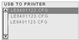
- When the [ENTER] key is pressed, the confirmation message is displayed. For the CFG files, the message included in the CFG file is displayed prior to the confirmation message.)
- The data is read from the USB memory. It takes 3 to 5 minutes to read all the information.
(2) PRINTER TO USB
This parameter is to save the firmware (BOOT/MAIN/CG/KANJI/HTML), storage area information, and parameter settings to a USB memory.
-
ALL
-
The confirmation message is displayed.
- The data is copied to the USB memory. It takes approx. 40 seconds to save all information.
A file is automatically created in the USB memory and named in the following format based on the printer model and saved date.
/ATAO/SYSTEM/LE840-0927.DAT
(e.g. LE840(203dpi model), Sep 27)
2.6.12 Copying Data to/from USB Memory (Cont.)
While using the USB memory, the following error message may be displayed.
| Error message | Description |
| FORMAT ERRORCheck the settings. | Format errorUSB memory is not connected. |
| MEMORY WRITE ERR.Check the dataand the settings. | Write error |
| MEMORY READ ERR.Check the dataand the settings. | Read error |
| MEMORY FULLFree some memoryspace. | Insufficient free space |
| FILE NOT FOUNDCheck the dataand the settings. | Specified file is not found. |
| UNKNOWN ERROR | Other errors |
Depending on the remaining memory size or the USB memory status, a write error may occur even under the insufficient free space condition.
2.7 Installing the Printer Drivers
2.7.1 Introduction
This chapter describes the use of the Oki Data printer driver for the Oki Data label printer on your Windows host computer; how to install and delete the printer driver and the procedure for adding a LAN port Cautions and limitations.
2.7.2 General Description
(1) Features
Once you install the Oki Data printer driver on your Windows host computer, you can use the Oki Data label printer in the same way you would a laser or ink jet printer.
You can use the printer by connecting a USB or LAN cable to your host computer.
(2) System Requirements
To install the Oki Data printer driver on your host computer the following system requirements are needed.
- Operating system: Windows XP, Windows Server 2003, Windows Vista, Windows Server 2008, Windows 7 or Windows Server 2008 R2
- Hardware: A DOS-/V (IBM PC/AT compatible) machine running an above operating system.
- Interface: - USB interface
- LAN interface
2.7.3 Installing the Printer Driver
The installation procedure of the printer driver differs depending on the printer model and the connection method. If an older version of the printer driver has been already installed, you must uninstall it and restart the computer before installing a newer version. See Section 2.7.6 Uninstalling the Printer Driver.
■ Installation method for each operating system
2.7.4 Installation under Windows XP/Server 2003/Vista/Server 2008/7/Server2008 R2
Use the following procedure to install the printer driver.
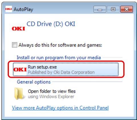
(1) Insert the LE840/LE850 CD-ROM into your PC's CD-ROM drive. Click on [Run setup.exe] when the "Auto Play" screen is displayed.
- If the menu screen does not appear, run "setup.exe" on this CD.
(2) If the [User Account Control] dialog box is displayed, click on [Yes] or [Continue].
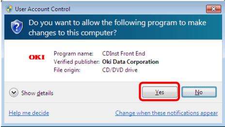
For Windows 7/Server 2008 R2
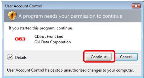
For Windows Vista/Server 2008
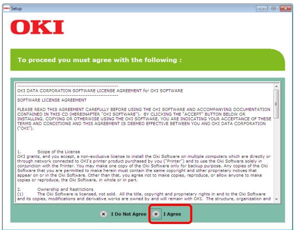
(3) After reading the license agreement, click on [I Agree].
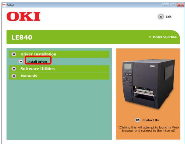
(4) Click on [Install Driver].
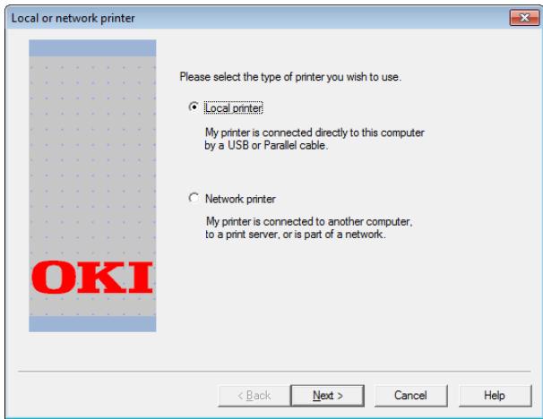
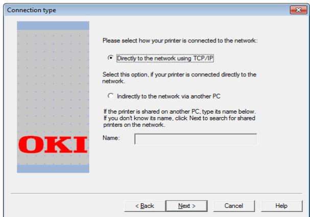
(5) When the [Local or network printer] screen appears, select the type of printer being used, and then click on [Next].
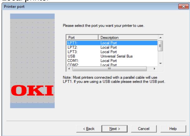
(6) Click the interface being used, and then click on [Next].
Local printer
Network printer
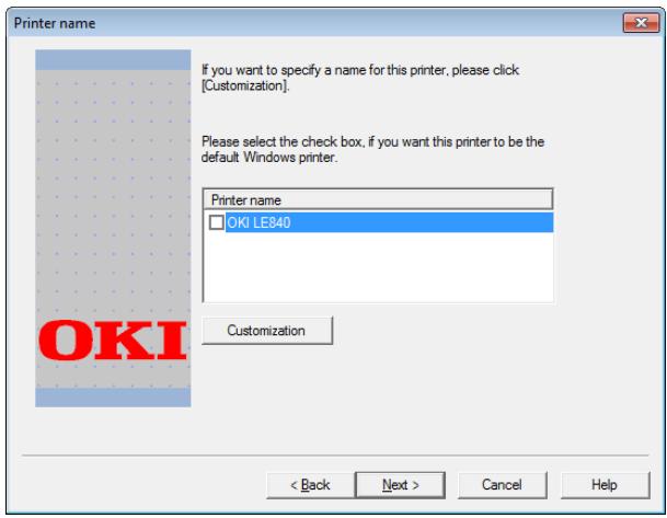
(7) If the [Printer name] screen appears, set the default printer and printer name if necessary, and then click on [Next].
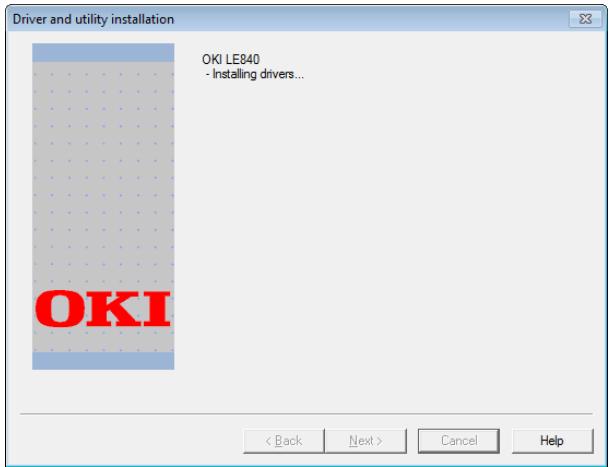
(8) A screen appears indicating that the installation is in progress. Please wait for the installation to complete.
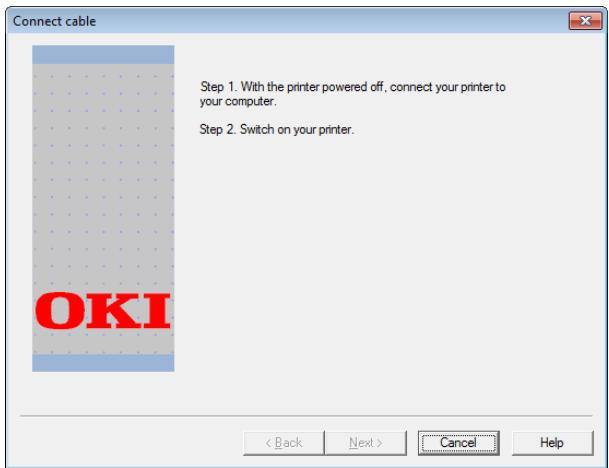
(9) If the [Connect cable] screen appears, connect the PC and printer, and then turn the printer's power on.
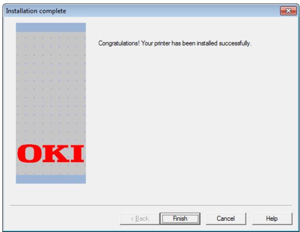
(10) When the [Installation complete] screen appears, installation is complete.
2.7.5 Uninstalling the Printer Driver
2.7.5.1 For Windows 7/Server 2008 R2
Uninstall procedure:
(1) Open the [Printer Folder] (^*)
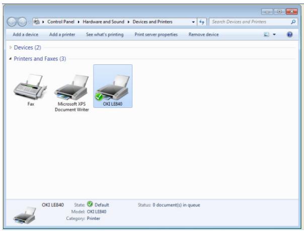
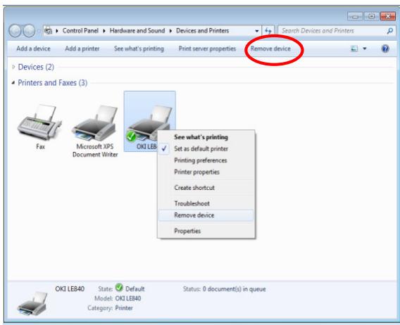
(2) Select "OKI LE840/LE850" in the [Printers and Faxes] section, and then click [Remove device].
Another way is to right click the mouse.
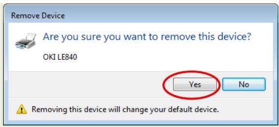
(3) Click [Yes].
(4) Select an installed printer (such as "Fax" or "Microsoft XPS Document Writer") in the [Printers and Faxes] section and then click [Print server properties].
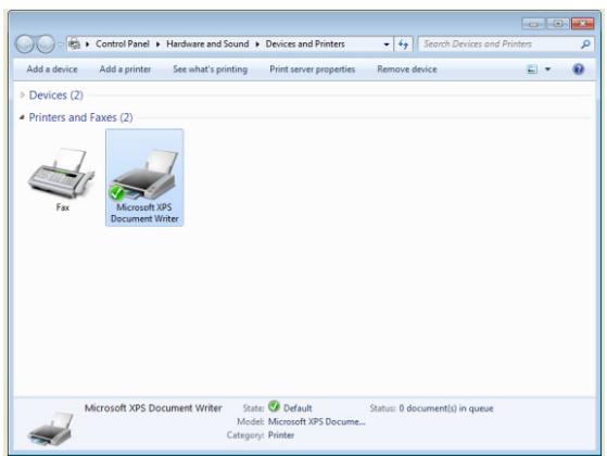
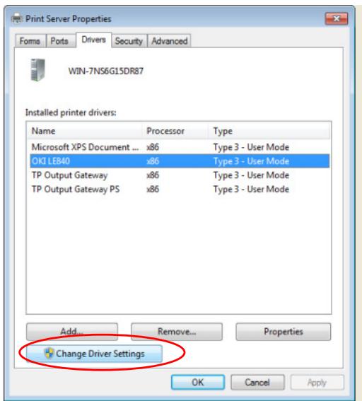
(5) For Windows 7 Click the [Drivers] tab and then click [Change Driver Settings].
For Server 2008 R2 Click [Drivers].
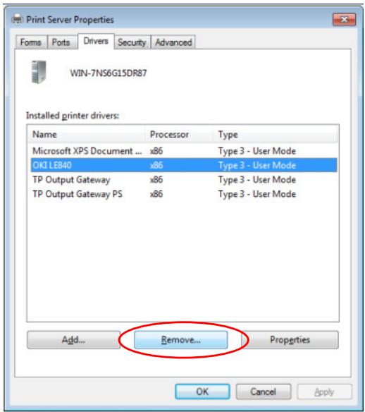
(6) Select "OKI LE840/LE850" from the "Installed printer drivers" list and then click [Remove].
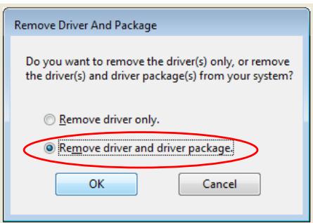
(7) Select [Remove driver and driver package.] and then click [OK].
(8) Click [Yes].
(9) Click [Delete].
(10) Click [OK] after driver removal completes and then click [Close] to exit the [Print Server Properties] dialog box.
Then, turn off the printer and restart your computer.
2.7.5.2 For Windows Vista/Server 2008
If the [User Account Control] dialog box is displayed, click [Continue].
Uninstall procedure:
(1) Open the [Printer Folder].
See the [Printer folder] procedure in "3.1 How to use this manual" for instructions on how to open the screen in each OS.
(2) Select "OKI LE840" from the "printers folder" and then select [Organize] [Delete].
(3) When "Are you sure you want to delete OKI LE840?" appears, click [Yes].
(4) Select [Organize] [Layout] [Menu Bar].
(5) Select [File] [Run as administrator] [Server Properties].
If you logged on to Server 2008 using the built-in administrator account, select [Files] → [Server Properties].
(6) Click the [Drivers] tab, select "OKI LE840" from the "Installed printer drivers" list, and then click [Remove].
(7) When the [Remove Driver And Package] screen is displayed, select [Remove driver and driver package], and then click [OK].
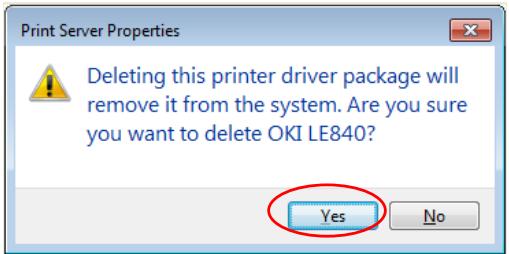
(8) When the "Deleting this printer driver package will remove it from the system. Are you sure you want to delete OKI LE840?" screen appears, click [Yes].
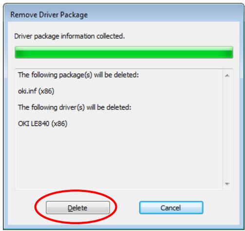
(9) When the [Remove Driver And Package] screen appears, click [Delete].
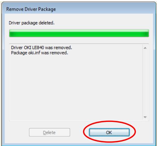
(10) Click [OK] after driver removal completes and then click [Close] to exit the [Print Server Properties] dialog box.
(11) Turn off the printer and restart your computer.
2.7.5.3 Other OS
Uninstall procedure:
(1) Open the [Printer Folder].
* See the [Printer folder] procedure in "3.1 How to use this manual" for instructions on how to open the screen in each OS.
(2) Select "OKI LE840" from the "printers folder" and then select [File] → [Delete].
(3) When "Are you sure you want to delete OKI LE840?" appears, click [Yes].
(4) Select [File] [Server Properties].
(5) Click the [Drivers] tab, select "OKI LE840" from the "Installed printer drivers" list, and then click [Remove].
(6) When the [Print Server Properties] screen appears, click [Yes].
(7) Click [Close] after driver removal is complete to exit the [Print Server Properties] dialog box.
(8) Turn off the printer and restart your computer.
2.8 Print Test
After your operating environment has been set, perform a print test.
- Perform a print test by using the Printer Driver or an Issue Command.
The printer driver's Properties screen allows you to set the communication conditions, media size, and other printing conditions in accordance with your operating environment. For details, refer to the Help for the Windows Printer Drivers screen.
Example: Stock tab display of the Printer Driver's Properties Screen
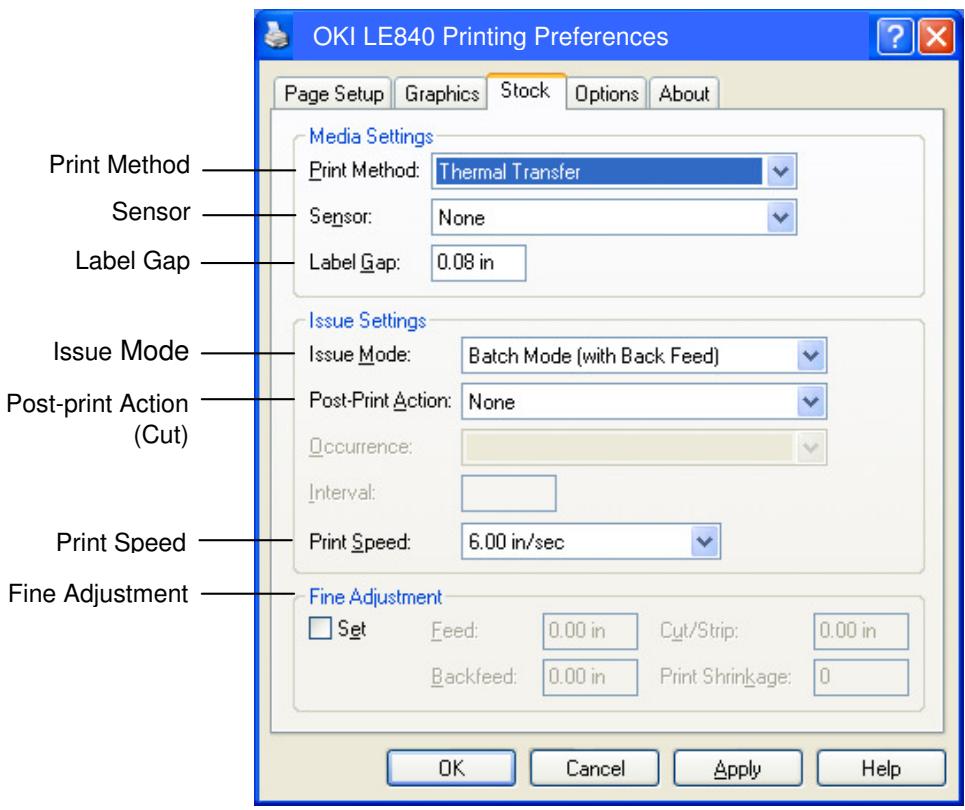
Print Method: Direct thermal or thermal transfer is selectable.
Sensor: Media sensor type is selectable.
Issue Mode: Batch, strip or cut is selectable.
Post-print Action: Whether to use the cutter or not is selectable.
Fine Adjustment: Adjustment values for the feed amount, cut/strip position, etc. can be set.
-
Confirm the print test result.
-
When a print start position, cut/strip position, or print tone needs to be adjusted: Section 2.9 Position and Print Tone Fine Adjustment
- When pre-printed media is used, and if a print start position is not properly detected: Section 2.10 Threshold Setting
2.8 Print Test (Cont.)
■ When using a Strip Module or an optional Cutter Module
It is necessary to set the issue mode, cut/strip position, etc. on the Printer Driver or with TPCL in accordance with your printing condition.
For details of the TPCL, refer to the LE840/LE850 External Equipment Interface Manual
Regarding how to use the Printer Driver, refer to the Help for the Windows Printer Drivers screen.
To gain maximum performance and life from the Cutter Module or Strip Module, periodic cleaning is required.
Before starting a cleaning, be sure to TURN OFF the printer to avoid risk of injury.
For details of cleaning, refer to Section 4.1.3 Optional Cutter Module.
2.9 Position and Print Tone Fine Adjustment
This section describes how to fine adjust a print start position, cut/strip position, reverse feed amount, print tone, and ribbon motor torque. When a fine adjustment is required, follow the procedure below.
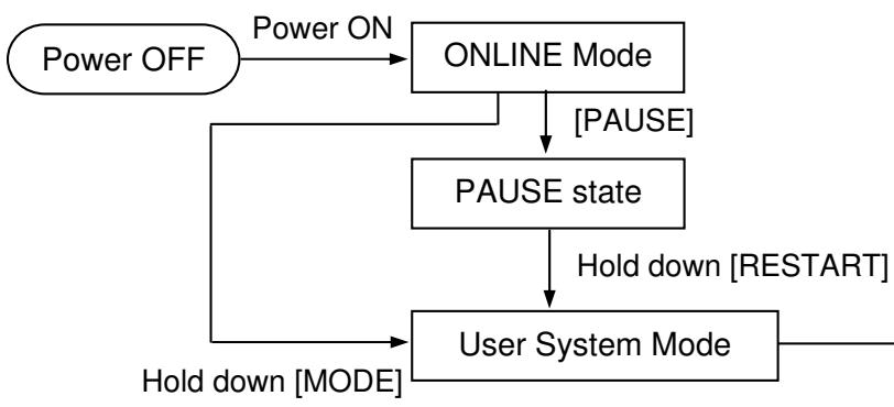
- Reset
Parameter setting ( Section 2.6.2) - Fine adjustment (⇒Section 2.9)
LAN/WLAN ( Section 2.6.3)
BASIC ( Section 2.6.4)
Z-MODE ( Section 2.6.5)
AUTO calibration ( Section 2.6.6) - Dump mode (⇒Section 2.6.7)
Log () Section 2.6.8)
2.9.1 Fine Adjustment
USER SYSTEM MODE
| ▲ | <1>RESET |
| ▲ | <2>PARAMETER SET |
| ▲ | <3>ADJUST SET |
| ▼ | <4>LAN/WLAN |
Contents of the Fine Adjustment Menu
| Menu | Parameter | |
| Adjust set | FEED ADJ. | Adjusts the feed amount to the print start position |
| CUT ADJ. | Adjusts the cut or strip position. | |
| BACK ADJ. | Adjusts the reverse feed amount. | |
| X ADJUST | Adjusts the print position in X coordinate (horizontal direction) | |
| TONE ADJ. (TRANS.) | Adjusts the print tone for thermal transfer printing. | |
| TONE ADJ. (DIRECT) | Adjusts the print tone for direct thermal printing. | |
| RBN ADJ. <FW> | Adjusts the ribbon take-up motor drive voltage. | |
| RBN ADJ. <BK> | Adjusts the ribbon feed motor drive voltage. | |
| THRESHOLD <REFL.> | Sets a fine adjustment value for the threshold for the reflective sensor (Black mark sensor). | |
| THRESHOLD <TRANS.> | Sets a fine adjustment value for the threshold for the transmissive sensor (Gap sensor). | |
| NOTE: The printer driver's properties screen also has Parameter Fine Adjustment menu. |
2.9.1 Fine Adjustment (Cont.)
(1) FEED ADJ.
Print start position is shifted by fine adjusting the feed amount.
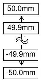
- Example of Print Start Position Fine Adjustment
When setting +3.0mm
Compared with +0.0mm position, the print start position is shifted forward.
When setting +0.0mm
When setting -3.0mm
Compared with “+0.0mm” position, the print start position is shifted backward.
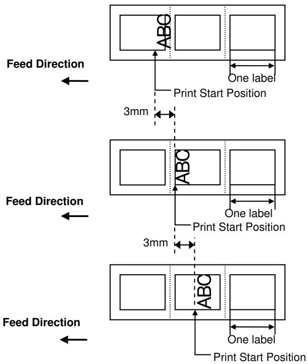
NOTE:
Do not set the fine adjustment value which is larger than the media pitch. When the set value exceeds the media pitch, the printer operation is not guaranteed.
2.9.1 Fine Adjustment (Cont.)
Cut position or peel-off position is shifted by fine adjusting the feed amount. Cut Position: Peel-off Position
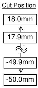
(2) CUT ADJ.
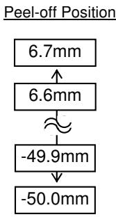
- Example of Cut Position Fine Adjustment
When setting +3.0mm
Compared with +0.0mm position, the cut position is shifted forward.
When setting +0.0mm
When setting -3.0mm
Compared with “+0.0mm” position, the cut position is shifted backward.


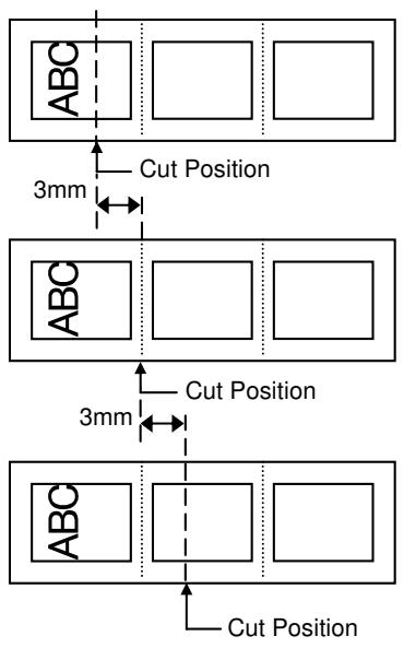
- Example of Peel-off Position Fine Adjustment
When setting -3.0mm
Compared with +0.0mm position, the peel-off position is shifted backward.
When setting +0.0mm
When setting +3.0mm
Compared with +0.0mm position, the peel-off position is shifted forward.
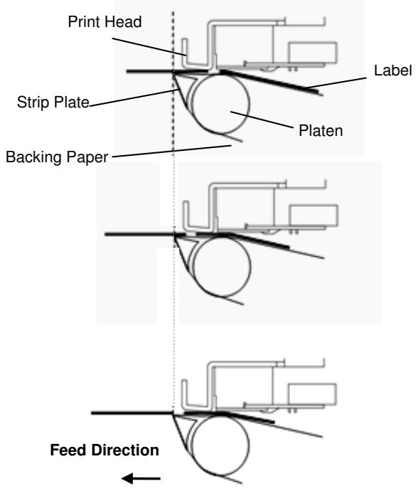
2.9.1 Fine Adjustment (Cont.)
(3) BACK ADJ.
Reverse feed amount to the next print start position is fine adjusted.
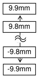
- Example of Reverse Feed Amount Fine Adjustment
When setting +3.0mm
Compared with “+0.0mm” position, the print start position after a reverse feed is shifted forward.
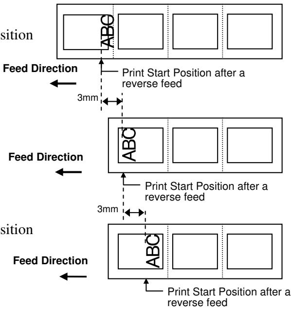
When setting +0.0mm
When setting -3.0mm
Compared with “+0.0mm” position, the print start position after a reverse feed is shifted backward.
NOTE:
Depending on the print conditions, a label may not return to the home position with a reverse feed, even if a reverse feed amount is specified to the same length as the forward feed.
On the following conditions, the media may not return to the home position, resulting in an error.
- The media sensor is used.
- The media pitch is almost the same as the distance between the print head and the media sensors (75.5 mm.)
- A printer action includes a reverse feed (such as cut issues, strip issues, and automatic forward feed standby.)
To prevent an error from occurring, the reverse feed amount needs to be increased by performing the back feed fine adjustment in the positive (+) direction.
2.9.1 Fine Adjustment (Cont.)
(4) X ADJUST
Print position in X-coordinate (horizontal direction) is fine adjusted.
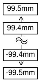
Example of X Coordinate Fine Adjustment
When setting -50.0mm
Compared with +0.0mm position, the print position is shifted to the left.
When setting +0.0mm
When setting +50.0mm
Compared with +0.0mm position, the print position is shifted to the right.
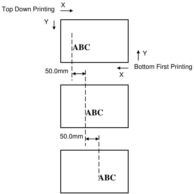
2.9.1 Fine Adjustment (Cont.)
(5) TONE ADJ.(TRANS.)
Print tone for the thermal transfer printing is fine adjusted.
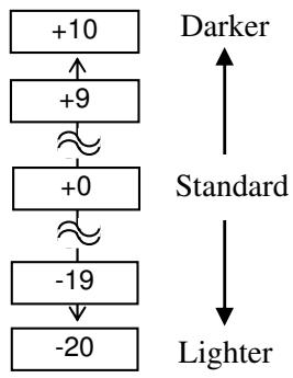
(6) TONE ADJ.(DIRECT.)
Print tone for the direct thermal printing is fine adjusted.
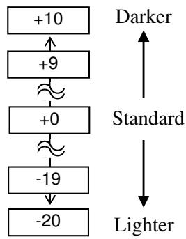
NOTE:
- The fine adjustment value is not effective for the reverse rotation.
- The fine adjustment value is limited depending on the print speed.
| Value | Print speed |
| -15 to 0 | All speed |
| +1 to +5 | 8 ips or less |
| +6 to +10 | 6 ips or less |
(7) RBN ADJ.
When the ribbon is slack or wrinkled and printing is affected, fine adjust the ribbon motor torque.
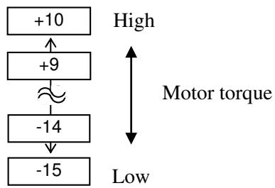
2.9.1 Fine Adjustment (Cont.)
NOTE:
- The fine adjustment value is not effective for the reverse rotation.
- The all fine adjustment values are applicable to every print speed.
(8) RBN ADJ.
When the ribbon is slack or wrinkled and printing is affected, fine adjust the ribbon motor torque.
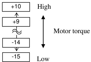
NOTE:
When "0.0 V" is set for this parameter, it is automatically corrected to 1.0V (default) after the power is turned OFF then ON.
(9) THRESHOLD
When you perform a threshold setting for the reflective sensor (Black mark sensor) and found the threshold needs to be adjusted, set a fine adjustment value.
This menu is accessible directly from the Threshold Setting Mode so that the threshold can be manually set right away.
Manually set threshold = Peak voltage - The value set here. For details, refer to Section 2.10.
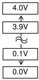
NOTE:
When "0.0 V" is set for this parameter, it is automatically corrected to 1.4V (default) after the power is turned OFF then ON.
(10) THRESHOLD
When you perform a threshold setting for the Transmissive sensor (Gap sensor) and found the threshold needs to be adjusted, set a fine adjustment value. This menu is accessible directly from the Threshold Setting Mode so that the threshold can be manually set right away.
Manually set threshold = Peak voltage - The value set here For details, refer to Section 2.10.
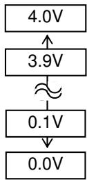
2.10 Threshold Setting
To maintain a constant print position the printer uses the media sensor to detect a print start position according to the difference of voltage between a print area and a gap or black mark. When the media is pre-printed, the darker (or more dense) inks can interfere with this process causing paper jam errors.
To get around this problem, first, try an automatic threshold setting.
If the problem still occurs, then, the threshold voltage needs to be fine adjusted.
Threshold is a voltage level by which the printer determines whether a print area or a gap/a black mark is being detected by the media sensor.
The threshold is a boundary between a print area and a gap/black mark, and should be a midpoint of their voltage levels.
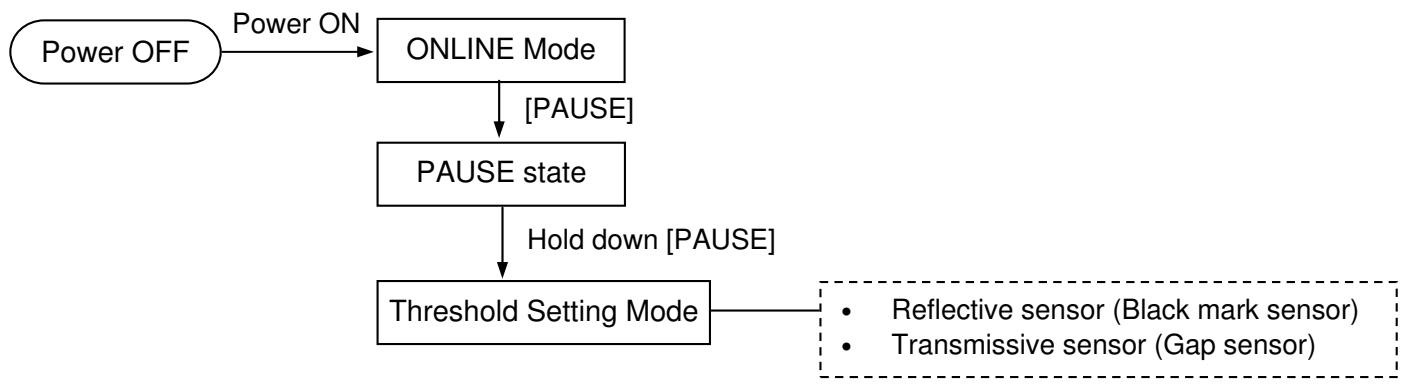
(1) Load the media to be used.
(2) Choose 1) or 2) depending on the sensor type to be used, then press the [ENTER].
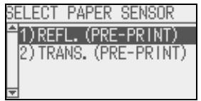
NOTES:
- Failure to feed more than 1.5 labels may result in an incorrect threshold setting.
- Ensure that a paper end or ribbon end error will not occur during paper feed.
(3) Hold down the [PAUSE] until more than 1.5 labels (tags) have been fed.
The media will continue to be fed until the [PAUSE] is released. (An automatic threshold setting for the selected sensor is completed by this operation.)
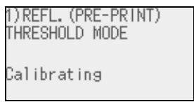
(4) The result of the threshold setting is displayed.
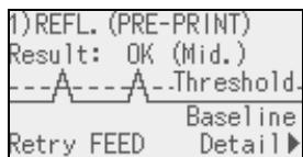
(e.g.: Succeeded)
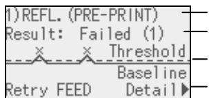
(e.g: Failed)
Sensor type
Result (Text)
Result (Graph)
Key operation guide
2.10 Threshold Setting (Cont.)
NOTE:
To make a threshold value set in this section effective, select the Transmissive Sensor (when using pre-printed media) or Reflective Sensor (when using manual threshold value) in Issue Command or the printer driver.
| Display example | Explanation | |
| 1 | Thresholds Baseline | Result: OK (Mid.) Threshold is at the midpoint between the peak and the baseline. |
| 2 | Thresholds Baseline | Result: OK (High) Threshold is near the peak voltage, so detection of a gap/black mark may fail if the voltage difference is very small. Adjusting the threshold to the midpoint between the peak and the baseline enables more accurate detection. Follow next (5) to (10) |
| 3 | Thresholds Baseline | Result: OK (Low) Threshold is near the baseline voltage, so detection of a gap/black mark may fail if the voltage difference is very small. Adjusting the threshold to the midpoint between the peak and the baseline enables more accurate detection. Follow next (5) to (10) |
| 4 | Thresholds Baseline | Failed (1) The media sensor cannot detect a gap/black mark. Sensor adjustment is required. (⇒Section 2.11) |
| 5 | Thresholds Baseline | Failed (1) The media sensor cannot detect a gap/black mark. (Threshold ≤ Baseline) Sensor adjustment is required. (⇒Section 2.11) |
| 6 | Thresholds Baseline | Failed (2) Detection by the media sensor is disabled. Sensor adjustment is required. (⇒Section 2.11) |
(5) To return to the sensor selection screen, press the [FEED]. To terminate the threshold setting, press the [ENTER]. To see the details, press the [RIGHT].
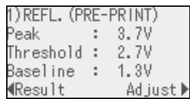
(e.g: Succeeded)
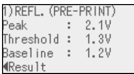
(e.g.: Failed)
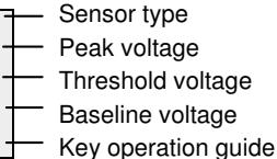
2.10 Threshold Setting (Cont.)
NOTE:
The threshold can be manually set as follows:
Manually set threshold = Peak voltage - Threshold fine adjustment value
e.g.) When Peak=3.5V and Fine adjustment value=1.0V, the threshold will be set to 2.5V.
(6) To return to the previous display, press the [LEFT].
To set a fine adjustment value, press the [RIGHT]. The threshold fine adjustment screen in ADJUST SET menu appears.
Set a value and press the [ENTER], [PAUSE] or [CANCEL].
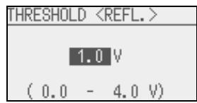
(7) The result after manually setting the threshold is displayed.
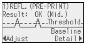
To set a fine adjustment value, press the [LEFT].
To return to the sensor selection screen, press the [FEED].
To terminate the threshold setting, press the [ENTER]. The printer is placed in Pause state.
(8) After the threshold is properly set, exit the threshold setting mode and place the printer in the user system mode to set the Threshold select parameter to Manual Set for the applicable sensor.
For details, refer to Section 2.6.2.2 Software Set.
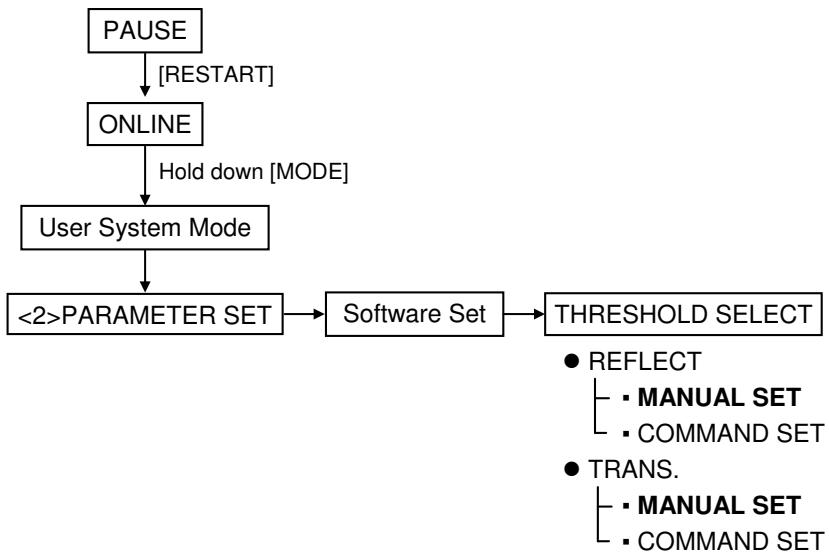
(9) Return to the User System Mode menu by pressing the [MODE]. Choose <1> RESET and press the [ENTER] to reboot the printer.
(10) When the printer is placed in the online mode, press the [FEED] to feed the media.
If a paper jam occurs or the media does not stop at the print start position, retry the threshold setting.
2.11 Sensor Setting
If a paper jam error still occurs even after a threshold setting has been performed, register the voltage level of media to the media sensor.
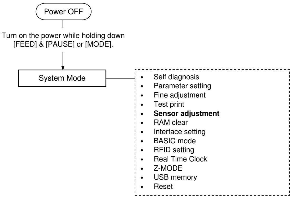
SYSTEM MODE
| ▲ | <3>ADJUST SET |
| <4>TEST PRINT | |
| <5>SENSOR ADJUST | |
| <6>RAM CLEAR |
Contents of the Sensor Adjust Menu
| Menu | Parameter | |
| Sensor Adjust | TEMPERATURE | Displays the ambient temperature and print head temperature. |
| REFLECT | Registers the voltage level of tag paper's print area to the reflective sensor (Black mark sensor). | |
| TRANS. | Registers the voltage level of label gap to the transmissive sensor (Gap sensor). | |
| PE REFL./TRANS. | Registers the voltage level of no paper to the reflective/transmissive sensor. | |
| RIBBON | Registers the voltage level of ribbon to the ribbon end sensor. | |
2.11 Sensor Setting (Cont.)
(1) REFLECT
- Select "REFLECT" from the Sensor Adjust menu.
- Place the tag paper to be used on the reflective sensor (Black mark sensor) so that the sensor can detect a print area.
- Hold down the [ENTER] for 3 seconds or more.
- When registration of the "print area level" is completed, "Adjust Complete" is displayed and an asterisk is shown on the right side of the voltage.
(2) TRANS.
- Select "TRANS." from the Sensor Adjust menu.
- Remove some labels and place the backing paper so that the Transmissive sensor (Gap sensor) can detect it.
- Hold down the [ENTER] for 3 seconds or more.
- When registration of the "label gap level" is completed, "Adjust Complete" is displayed and an asterisk is shown on the right side of the voltage.
(3) PE REFL./TRANS.
- Select "PE REFL./TRANS." from the Sensor Adjust menu.
- Remove any media from the media sensor.
- Hold down the [ENTER] for 3 seconds or more.
- When registration of the "no media level" is completed, "Adjust Complete" is displayed and an asterisk is shown on the right side of the voltage.
3. ONLINE MODE
This chapter describes the usage of the keys on the Operation Panel in Online mode.
When the printer is in Online mode and connected to a host computer, the normal operation of printing on labels or tags can be accomplished.
3.1 Key Functions
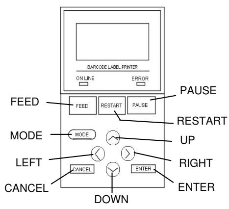
Key functions in the online mode
| Key | Function |
| [FEED] | (1) Feeds the set media length. |
| (2) Prints the data in the image buffer according to the system mode setting. | |
| (3) Clears the help message. | |
| [RESTART] | (1) Resumes printing after a temporary pause in printing or after an error. |
| (2) Places the printer in the initial state which is obtained when the power is turned on. | |
| (3) Places the printer in the user system mode. | |
| (4) Clears the help message. | |
| [PAUSE] | (1) Stops label printing temporarily. |
| (2) Programs the threshold values. | |
| (3) Clears the help message. | |
| [MODE] | (1) Places the printer in the user system mode. |
| (2) Clears the help message. | |
| [CANCEL] | (1) Clears the job. |
| (2) Displays previous help message page. | |
| [ENTER] | (1) Displays next help message page. |
| (2) Clears the help message. | |
| [UP] | (1) Scrolls up |
| [DOWN] | (1) Scrolls down |
| [LEFT] | (1) Displays previous help message page. |
| [RIGHT] | (1) Displays next help message page. |
3.2 LCD
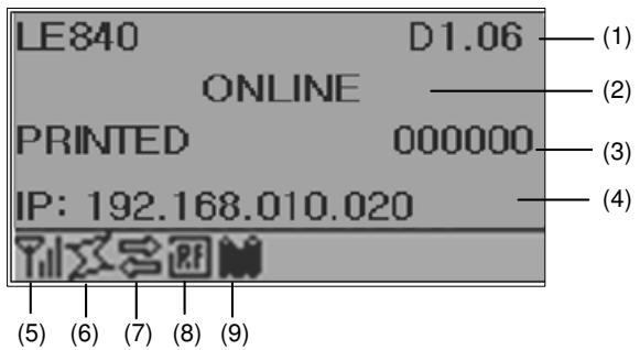
Online state
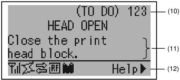
Error state
(Example: Head open error)
| No. | Description |
| (1) | Model name and firmware version |
| (2) | Message |
| (3) | The number of labels printed |
| (4) | IP address (only when LAN/WLAN is enabled.) |
| (5) | Radio intensity (only when WLAN is enabled.)Indicates the radio intensity in 4 levels. |
| (6) | WLAN connection (only when WLAN is enabled.)Lights up when connecting to an access point.Flashes while roaming.Goes off when disconnected. |
| (7) | Presence of a print jobAppears when a print job exists. |
| (8) | RFID (only when RFID module is installed.)Appears when a communication between the printer and the RFID module is enabled.Flashes while communicating with the RFID module. |
| (9) | Ribbon near endFlashes when a ribbon near end state is detected. |
| (10) | The number of remaining labels to print |
| (11) | Error description and solution |
| (12) | Help guideAppears when a help guide message is provided. Press the [RIGHT] key to see the help guide message. |
3.3 Operation Example
Online Mode
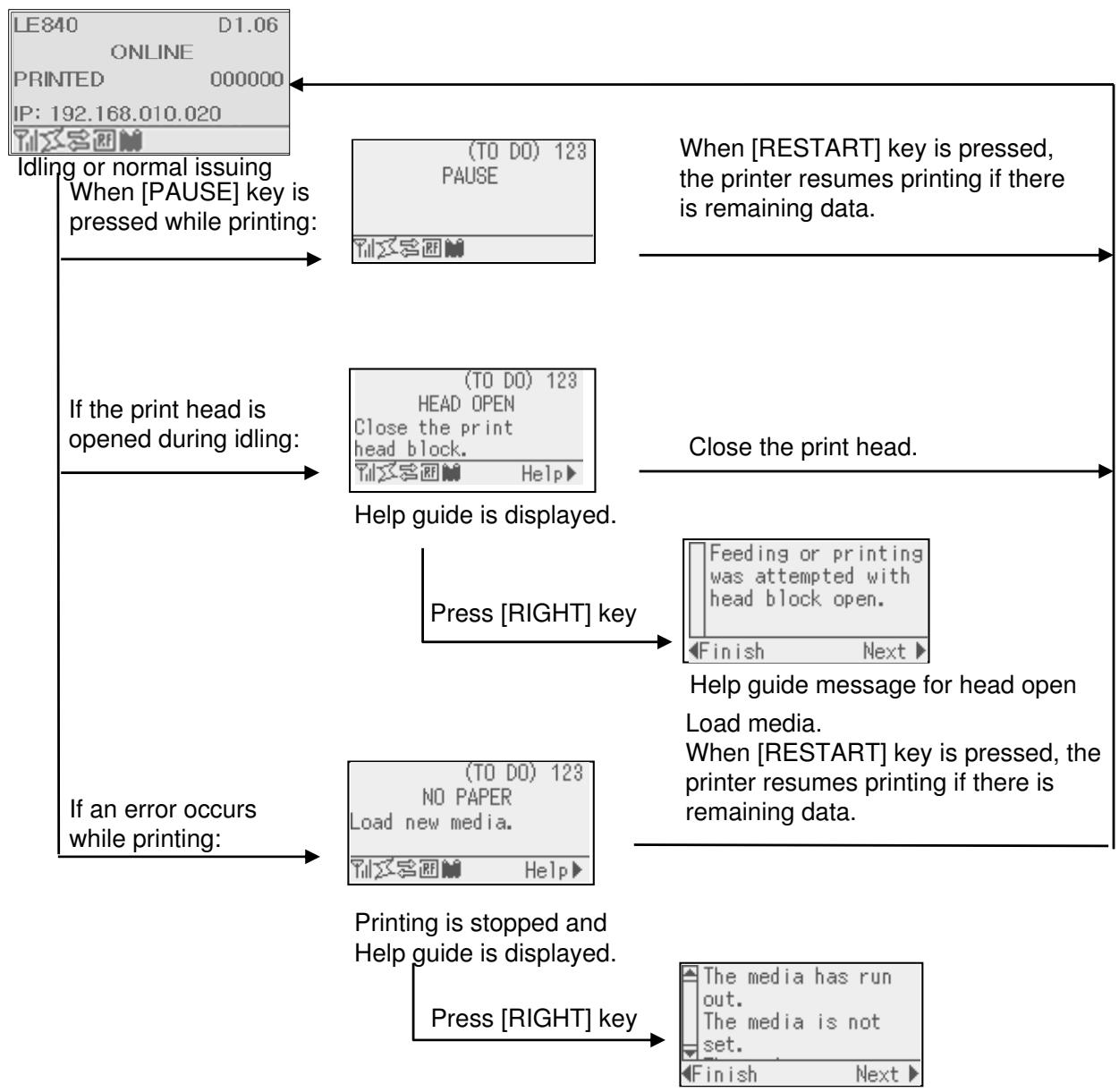
Help guide message for no paper
3.3 Operation Example (Cont.)
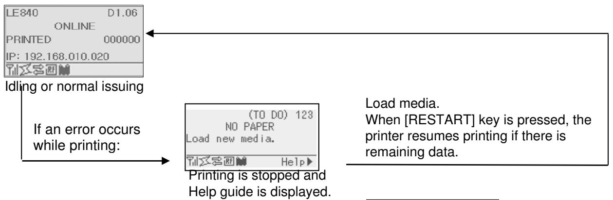
Help Guide Message
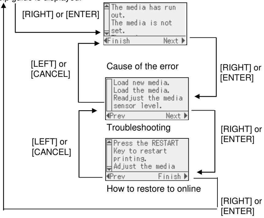
3.3 Operation Example (Cont.)
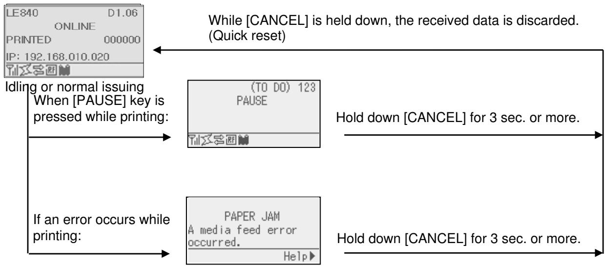
■ Cancellation of Print Job
3.4 Power Save Function
3.4.1 Entering the Power Saving Mode
When the printer stays in any of the following statuses for the specified length of time, it enters the power saving mode.
Online (Idle, communicating)
- Pause
Error
- Waiting for label to be removed
- System mode (except for self-diagnosis, test print, sensor adjustment)
- User system mode (except for dump)
- Pause state of the expansion I/O
When the printer enters the power saving mode, “POWER SAVING MODE” is displayed on the LCD and the backlight goes off.
POWERSAVINGMODE
When the following occurs in the power saving mode, the LCD wakes up.
- A key is pressed. (Except for [RESTART] or [FEED] key which causes printing or paper feed.)
- The head lever is released and locked.
- The status of the pause or active signal of the expansion I/O changes.
The LCD shows "POWER SAVING MODE" and the backlight goes off again if no status change occurs on the printer for 30 seconds.
3.4.2 Exiting the Power Saving Mode
The printer exits the power saving mode when:
- printing (printing caused by a depression of the [RESTART] key is included.) is performed.
- paper feed or re-print s caused by a depression of the [FEED] key
- printing or paper feed is initiated through the expansion I/O
- automatic calibration is performed
- sensor adjustment is performed in the system mode
- the printer receives commands - U1/U2, T, XS, IB or RFID-related commands
4. MAINTENANCE
WARNING!
- Be sure to disconnect the power cord before performing maintenance. Failure to do this may cause an electric shock.
- To avoid injury, be careful not to pinch your fingers while opening or closing the cover and print head block.
- The print head becomes hot immediately after printing. Allow it to cool before performing any maintenance.
- Do not pour water directly onto the printer.
- Do not touch any moving parts, projection and the edge of sheet metal.
This chapter describes how to perform routine maintenance.
To ensure the continuous high quality operation of the printer, you should perform a regular maintenance routine. For high usage it should be done on a daily basis. For low usage it should be done on a weekly basis.
4.1 Cleaning
To maintain the printer performance and print quality, please clean the printer regularly, or whenever the media or ribbon is replaced.
4.1.1 Print Head/Platen/Sensors
CAUTION!
- Do not use any volatile solvent including thinner and benzene, as this may cause discoloration to the cover, print failure, or breakdown of the printer.
-
Do not touch the Print Head Element with bare hands, as static may damage the Print Head.
-
Turn off the power and unplug the printer.
- Open the Top Cover.
- Turn the Head Lever to the "FREE" position, and then release the Ribbon Shaft Holder Plate.
- Open the Print Head Block.
- Remove the ribbon and media.
CAUTION!
When cleaning the print head, be careful not to damage the print head with hard objects like watches or rings.
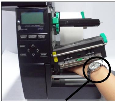
Care must be taken not to allow the metal or glass part of a watch to touch the print head edge.
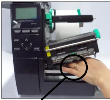
Care must be taken not to allow a metal object like a ring to touch the print head edge.
Since the print head element can be easily damaged by shock, please treat it carefully and do not hit it with hard objects.
4.1.1 Print Head/Platen/ Sensors (Cont.)
NOTE:
Please purchase the Print Head Cleaner from your authorised Oki Data service representative.
- Clean the Print Head Element with a Print Head Cleaner or a cotton swab or soft cloth slightly moistened with alcohol.
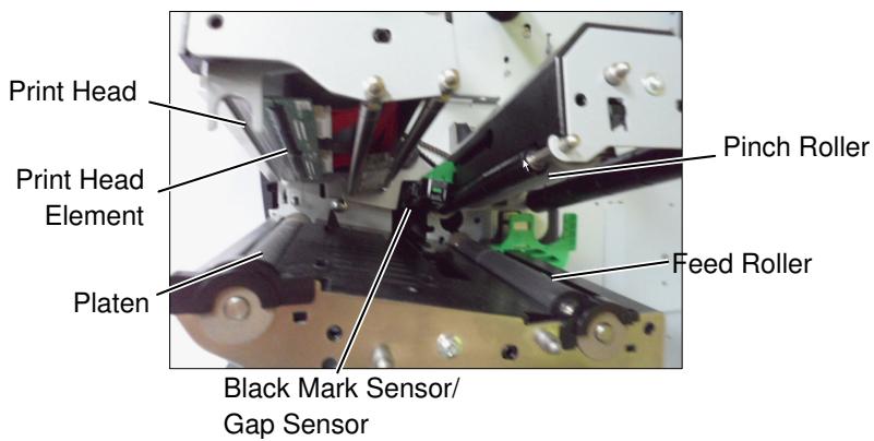
- Wipe the Platen, Feed Roller, and Pinch Roller with a soft cloth slightly moistened with alcohol. Remove dust or foreign substances from the internal parts of the printer.
- Wipe the Gap Sensor and Black Mark Sensor with a dry soft cloth.
4.1.2 Covers and Panels
CAUTION!
- DO NOT POUR WATER directly onto the printer.
- DO NOT APPLY cleaner or detergent directly onto any cover or panel.
- NEVER USE THINNER OR OTHER VOLATILE SOLVENT on the plastic covers.
- DO NOT clean the panel, covers, or the supply window with alcohol as it may cause them to discolour, lose their shape or develop structural weakness.
Wipe the covers and panels with a dry soft cloth or a cloth slightly moistened with a mild detergent solution.
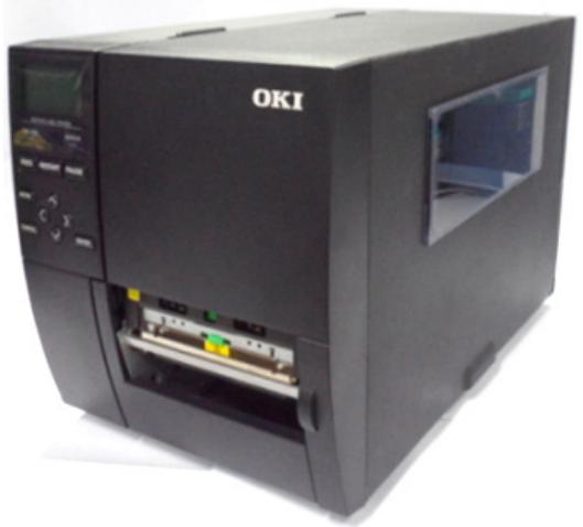
4.1.3 Optional Cutter Module
WARNING!
- Be sure to turn the power off before cleaning the Cutter Module.
- As the cutter blade is sharp, care should be taken not to injure yourself while cleaning.
The disc cutter and rotary cutter are available as an option. They are both cleaned in the same way. When removing the Cutter Cover of the rotary cutter unit, remove the screws from the bottom of the cover.
- Loosen the two Plastic Head Screws to remove the Cutter Cover.
- Remove the jammed paper.
- Clean the Cutter with a soft cloth slightly moistened with alcohol.
- Attach the Cutter Cover.
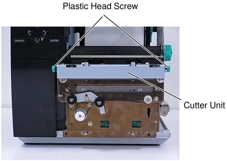
5. TROUBLESHOOTING
This chapter lists the error messages, possible problems, and their solutions.
| WARNING! |
| If a problem cannot be solved by taking the actions described in this chapter, do not attempt to repair the printer. Turn off and unplug the printer, then contact an authorised Oki Data service representative for assistance. |
5.1 Error Messages
NOTES:
- If an error is not cleared by pressing the [RESTART] key, turn the printer off and then on.
After the printer is turned off, all print data in the printer is cleared.
| Error Messages | Problems/Causes | Solutions |
| HEAD OPEN | The Print Head Block is opened in Online mode. | Close the Print Head Block. |
| Feeding or printing has been attempted with the Print Head Block open. | Close the Print Head Block. Then press the [RESTART] key. | |
| COMMS ERROR | A communication error has occurred. | Make sure the interface cable is correctly connected to the printer and the host and the host is turned on. |
| PAPER JAM | 1. The media is jammed in the media path. The media is not fed smoothly. | 1. Remove the jammed media, and clean the Platen. Reload the media correctly. Press the [RESTART] key. ⇒ Section 5.3. |
| 2. The media is not loaded properly. | 2. Reload the media correctly. Then press the [RESTART] key. ⇒ Section 2.3. | |
| 3. Wrong Media Sensor is selected for the media being used. | 3. Turn the printer off and then on. Select the Media Sensor for the media type being used. Resend the print job. | |
| 4. The Black Mark Sensor is not correctly aligned with the Black Mark on the media. | 4. Adjust the sensor position, then press the [RESTART] key. ⇒ Section 2.3.1. | |
| 5. Size of the loaded media is different from the programmed size. | 5. Replace the loaded media with one that matches the programmed size, press the [RESTART] key, or turn the printer off and then on, select a programmed size that matches the loaded media. Resend the print job. | |
| 6. Media sensor has not been properly calibrated for the media being used. | 6. Refer to Section 2.10 to set the threshold. If this does not solve the problem, turn off the printer, and call a Oki Data authorised service representative. | |
| Error Messages | Problems/Cause | Solutions |
| CUTTER ERROR(Only when the cutter module is installed on the printer.) | 1. The media is jammed in the cutter. | 1. Remove the jammed media. Press the [RESTART] key. If this does not solve the problem, turn off the printer, and call an Oki Data authorised service representative.⇒ Section 4.1.3. |
| 2. The Cutter Cover is not attached properly. | 2. Attach the Cutter Cover properly. | |
| NO PAPER | 1. The media has run out. | 1. Load new media. Press the [RESTART] key.⇒ Section 2.3.1. |
| 2. The media is not loaded properly. | 2. Reload the media correctly. Press the [RESTART] key.⇒ Section 2.3.1. | |
| 3. The media sensor position has not been adjusted properly. | 3. Adjust the sensor position. Press the [RESTART] key.⇒ Section 2.3.1. | |
| 4. Media sensor has not been properly calibrated for the media being used. | 4. Refer to Section 2.10 to set the threshold. If this does not solve the problem, turn off the printer, and call an Oki Data authorised service representative. | |
| 5. The media is slack. | 5. Take up any slack in the media. | |
| RIBBON ERROR | 1. The ribbon is not fed properly. | 1. Remove the ribbon and check the status of the ribbon. Replace the ribbon if necessary. If the problem is not solved, turn off the printer, and call an Oki Data authorised service representative. |
| 2. The ribbon is not loaded. | 2. Load a ribbon.⇒ Section 2.3.2 | |
| 3. The ribbon sensor has a problem. | 3. Turn off the printer and call an Oki Data authorised service representative. | |
| NO RIBBON | The ribbon has run out. | Load a new ribbon. Press the [RESTART] key.⇒ Section 2.3.2. |
| REWIND FULL | The Built-in Rewinder Unit is full. | Remove the backing paper from the Built-In Rewinder Unit. Press the [RESTART] key. |
| EXCESS HEAD TEMP | The Print Head has overheated. | Turn off the printer and allow it to cool down for about 3 minutes. If this does not solve the problem call an Oki Data authorised service representative. |
| HEAD ERROR | There is a problem with the Print Head. | Replace the Print Head. |
| POWER FAILURE | A momentary power failure has occurred. | Check that the power source, which supplies power to the printer, is the correct rating. If the printer shares the same power outlet with other electrical appliances that consume large amounts of power, use a different outlet. |
| Power off/on timing is too fast. | Turn on the printer after LED is not blinking. (Power turn on during LED blinking) | |
| SYSTEM ERROR | 1. The printer is used in a location where it is subject to noise or there are power cords from other electrical appliances near the printer or interface cables. | 1. Keep the printer and the interface cables away from the source of noise |
| 2. The Power Cord of the printer is not grounded. | 2. Ground the Power Cord. | |
| 3. The printer shares the same power source with any other electrical appliances. | 3. Provide an exclusive power source for the printer. | |
| 4. An application software used on your host computer has an error or malfunction. | 4. Confirm the host computer operates properly. | |
| MEMORY WRITE ERR. | An error has occurred in writing to the flash ROM/USB memory. | Turn the printer off, and then on again. |
| FORMAT ERROR | An error has occurred in formatting the flash ROM/USB memory. | Turn the printer off, and then on again. |
| MEMORY FULL | Saving failed because of insufficient storage space in the flash ROM/USB memory. | Turn the printer off, and then on again. |
| EEPROM ERROR | Data cannot be read-from or written-to a backup EEPROM properly. | Turn the printer off, and then on again. |
| RFID WRITE ERROR | The printer did not succeed in writing data onto an RFID tag after retrying the specified number of times. | Press the [RESTART] key. |
| RFID ERROR | The printer cannot communicate with the RFID module. | Turn the printer off, and then on again. |
| LOW BATTERY | The voltage of the Real Time Clock Battery is low. | If you wish to keep using the same battery even after “LOW BATTERY” error occurs, turn off the printer and start it in the system mode, set the date and time for the RTC and reboot the printer. As long as the power is on the date and time will be correct. Call an Oki Data authorised service representative to replace the battery. |
| SYNTAX ERROR | While the printer is in the Download mode for upgrading the firmware, it receives an improper command, for example, an Issue Command. | Turn the printer off, and then on again. |
| PASSWORD INVALID Please Power OFF | A wrong password was entered three consecutive times. | Please consult the system administrator. |
| Other error messages | A hardware or software problem may have occurred. | Turn the printer off and then on. If this does not solve the problem, turn off the printer, and call an Oki Data authorised service representative. |
5.2 Possible Problems
This section describes problems that may occur when using the printer, and their causes and solutions.
| Possible Problems | Causes | Solutions |
| The printer will not turn on. | 1. The Power Cord is disconnected. | 1. Plug in the Power Cord. |
| 2. The AC outlet is not functioning correctly. | 2. Test with a power cord from another electrical appliance. | |
| 3. The fuse has blown, or the circuit breaker has tripped. | 3. Check the fuse or circuit breaker. | |
| The media will not feed. | 1. The media is not loaded properly. | 1. Load the media properly.⇒Section 2.3.1. |
| 2. The printer is in an error condition. | 2. Solve the error in the message display.(See Section 5.1 for more detail.) | |
| Pressing the [FEED] key in the initial state results in an error. | A feed was attempted contrary to the following default conditions.Sensor type: Gap sensor Printing method: Thermal transfer Media pitch: 76.2 mm | Change the print condition by using the printer driver or a print command so that it corresponds to your printing conditions.Clear the error state by pressing the [RESTART] key. |
| Nothing is printed on the media. | 1. The media is not loaded properly. | 1. Load the media properly.⇒Section 2.3.1. |
| 2. The ribbon is not loaded properly. | 2. Load the ribbon properly.⇒Section 2.3.2. | |
| 3. The print head is not installed properly. | 3. Install the print head properly and close the Print Head Block. | |
| 4. The combination of the ribbon and media is not correct. | 4. Select an appropriate ribbon for the media type being used. | |
| The printed image is blurred. | 1. The combination of the ribbon and media is not correct. | 1. Select an appropriate ribbon for the media type being used. |
| 2. The Print Head is not clean. | 2. Clean the print head using the Print Head Cleaner or a cotton swab slightly moistened with ethyl alcohol. | |
| The cutter does not cut. | 1. The Cutter Cover is not attached properly. | 1. Attach the Cutter Cover properly. |
| 2. The media is jammed in the Cutter. | 2. Remove the jammed paper.⇒Section 4.1.3. | |
| 3. The cutter blade is dirty. | 3. Clean the cutter blade.⇒Section 4.1.3. | |
| The Strip Module does not remove labels from the backing paper. | Label stock is too thin or the glue is too sticky. | 1. Refer to Section 7.1 Media and change the label. |
| 2. Set the Pre Peel function to ON.⇒Section 2.6.2. |
5.3 Removing Jammed Media
CAUTION!
Do not use any tool that may damage the Print Head.
WARNING!
- Be sure to disconnect the power cord before performing maintenance. Failure to do this may cause an electric shock.
- To avoid injury, be careful not to pinch your fingers while opening or closing the cover and print head block.
- The print head becomes hot immediately after printing. Allow it to cool before performing any maintenance.
- Do not pour water directly onto the printer.
- Do not touch any moving parts, projection and the edge of sheet metal.
NOTE:
If you get frequent jams in the cutter, contact an Oki Data authorised service representative.
This section describes, in detail, how to remove jammed media from the printer.
- Turn off and unplug the printer.
- Open the Top Cover.
- Turn the Head Lever to FREE position, then open the Ribbon Shaft Holder Plate.
- Open the Print Head Block.
- Remove the ribbon and media.
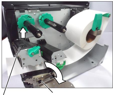
Print Head Block
Ribbon Shaft Holder Plate
- Remove the jammed media from the printer. DO NOT use any sharp implements or tools as these could damage the printer.
- Clean the Print Head and Platen, then remove any further dust or foreign substances.
- Paper jams in the Cutter Unit can be caused by wear or residual glue from label stock on the cutter. Do not use non-specified media in the cutter.
CAUTION!
When removing the jammed media, be careful not to damage the print head with hard objects like watches or rings.
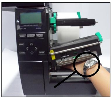
Care must be taken not to allow the metal or glass part of a watch to touch the print head.
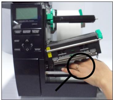
Care must be taken not to allow a metal object like a ring to touch the print head.
Since the print head element can be easily damaged by shock, please treat it carefully and do not hit it with hard objects.
6. PRINTER SPECIFICATIONS
This section describes the printer specifications.
| Item\Model | LE840Ds | LE840Dn | LE840Du | |
| Dimension (W x D x H) | 278 mm x 460 mm x 310 mm (10.9" x 18.1" x 12.2") | |||
| Weight (kg) | 17 kg | 17 kg | 15 kg | |
| Operating temperature range | 5 degC to 40 degC (40 degF to 104 degF) | |||
| Relative humidity | 25% to 85% RH (no condensation) | |||
| Storage Temperature | -40 degC to +60 degC | |||
| Storage Humidity | 10%RH to 90%RH (non condensation) | |||
| Power supply | Universal switching power source AC 100 V to 240 V, 50/60 Hz | |||
| Input voltage | AC100 V to 240 V, 50/60 Hz | |||
| Power Consumption | During a print job* | 157.34W 0.71A | ||
| During stand-by | Less than 15W (Option full-operating), 0.19A | |||
| During sleep mode | 5.7W 0.09A | |||
| Resolution | 8 dots/mm (203 dpi) | |||
| Printing method | Direct Thermal | |||
| Printing speed | 76.2mm/sec. (3 in/sec.)152.4mm/sec (6 in/sec.)254.0mm/sec.(10 in/sec.)304.8mm/sec.(12 in/sec.) | |||
| Available media width (including backing paper) | 25.0 mm to 114.0 mm (0.98 inches to 4.49 inches) | |||
| Effective print width (max.) | 104.0 mm (4.1 inches) | |||
| Issue mode | BatchStrip (Strip mode is enabled only when the optional Strip Module is installed.)Cut (Cut mode is enabled only when the optional Cutter Module is installed.) | |||
| LCD Message display | Graphic type 128 x 64 dots | |||
*: While 20% slant lines are printed in the specified format.
| Item\Model | LE840Ds | LE840Dn | LE840Du |
| Bar code types | JAN8, JAN13, EAN8, EAN8+2 digits, EAN8+5 digits, EAN13, EAN13+2 digits, EAN13+5 digits, UPC-E, UPC-E+2 digits, UPC-E+5 digits, UPC-A, UPC-A+2 digits, UPC-A+5 digits, MSI, ITF, NW-7, CODE39, CODE93, CODE128, EAN128, Industrial 2 to 5, Customer Bar Code, POSTNET, KIX CODE, RM4SCC (ROYAL MAIL 4 STATE CUSTOMER CODE), GS1 DataBar , Standard 2 of 5 , USPS Intelligent Mail Barcode | ||
| Two-dimensional code | Data Matrix, PDF417, QR code, Maxi Code, Micro PDF417, CP Code | ||
| Font | Times Roman (6 sizes), Helvetica (6 sizes), Presentation (1 size), Letter Gothic (1 size), Prestige Elite (2 sizes), Courier (2 sizes), OCR (2 types), Gothic (1 size), Outline font (4 types), Price font (3 types) | ||
| Rotations | 0, 90, 180, 270 deg | ||
| Standard interface | USB, Parallel, Serial | USB, LAN | USB |
| Optional interface | Serial interface Parallel interface Expansion I/O interface RTC & USB Host interface Wireless LAN interface Note: Serial I/F and Wireless LAN I/F are exclusive connection | ||
| Standard Module | Strip module | Strip module | N/A |
| Optional Module | Cutter module Strip module Cutter module and Strip module are exclusive connection | ||
| Optional Kit | 203-dpi print head300-dpi print head | ||
| NOTES:· Data MatrixTM is a trademark of International Data Matrix Inc., U.S.· PDF417TM is a trademark of Symbol Technologies Inc., US.· QR Code is a trademark of DENSO CORPORATION.· Maxi Code is a trademark of United Parcel Service of America, Inc., U.S. | |||
| Item\Model | LE840Ts | LE840Tn | LE840Tu | |
| Dimension (W x D x H) | 278 mm x 460 mm x 310 mm (10.9” x 18.1” x 12.2”) | |||
| Weight (kg) | 17 kg | |||
| Operating temperature range | 5 degC to 40 degC (40 degF to 104 degF) | |||
| Relative humidity | 25% to 85% RH (no condensation) | |||
| Storage Temperature | -40 degC to +60 degC | |||
| Storage Humidity | 10%RH to 90%RH (non condensation) | |||
| Power supply | Universal switching power source AC 100 V to 240 V, 50/60 Hz | |||
| Input voltage | AC100 V to 240 V, 50/60 Hz | |||
| Power Consumption | During a print job* | 157.34W 2.0A-0.7A | ||
| During stand-by | Less than 15W (Option full-operating), 0.19A | |||
| During sleep mode | 5.7W 0.09A | |||
| Resolution | 8 dots/mm (203 dpi) | |||
| Printing method | Thermal Transfer or Direct Thermal | |||
| Printing speed | 76.2mm/sec. (3 in/sec.)152.4mm/sec (6 in/sec.)254.0mm/sec.(10 in/sec.)304.8mm/sec.(12 in/sec.) | |||
| Available media width (including backing paper) | 25.0 mm to 114.0 mm (0.98 inches to 4.49 inches) | |||
| Effective print width (max.) | 104.0 mm (4.1 inches) | |||
| Issue mode | BatchStrip (Strip mode is enabled only when the optional Strip Module is installed.)Cut (Cut mode is enabled only when the optional Cutter Module is installed.) | |||
| LCD Message display | Graphic type 128 x 64 dots | |||
*: While 20% slant lines are printed in the specified format.
| Item\Model | LE840Ts | LE840Tn | LE840Tu |
| Bar code types | JAN8, JAN13, EAN8, EAN8+2 digits, EAN8+5 digits, EAN13, EAN13+2 digits, EAN13+5 digits, UPC-E, UPC-E+2 digits, UPC-E+5 digits, UPC-A, UPC-A+2 digits, UPC-A+5 digits, MSI, ITF, NW-7, CODE39, CODE93, CODE128, EAN128, Industrial 2 to 5, Customer Bar Code, POSTNET, KIX CODE, RM4SCC (ROYAL MAIL 4 STATE CUSTOMER CODE), GS1 DataBar, Standard 2 of 5 , USPS Intelligent Mail Barcode | ||
| Two-dimensional code | Data Matrix, PDF417, QR code, Maxi Code, Micro PDF417, CP Code | ||
| Font | Times Roman (6 sizes), Helvetica (6 sizes), Presentation (1 size), Letter Gothic (1 size), Prestige Elite (2 sizes), Courier (2 sizes), OCR (2 types), Gothic (1 size), Outline font (4 types), Price font (3 types) | ||
| Rotations | 0, 90, 180, 270 deg | ||
| Standard interface | USB, Parallel, Serial | USB, LAN | USB |
| Optional interface | Serial interface Parallel interface Expansion I/O interface RTC & USB Host interface Wireless LAN interface Note: Serial I/F and Wireless LAN I/F are exclusive connection. | ||
| Optional Module | Cutter module Strip module Cutter module and Strip module are exclusive connection. | ||
| Optional Kit | 203-dpi print head300-dpi print head | ||
NOTES:
- Data Matrix™ is a trademark of International Data Matrix Inc., U.S.
- PDF417™ is a trademark of Symbol Technologies Inc., US.
- QR Code is a trademark of DENSE CORPORATION.
Maxi Code is a trademark of United Parcel Service of America, Inc., U.S.
7. SUPPLY SPECIFICATIONS
7.1 Media
Please make sure that the media being used is approved by Oki Data. The warranty does not apply when a problem is caused by using media that is not approved by Oki Data.
For information regarding Oki Data approved media, please contact a Oki Data authorised service representative.
7.1.1 Media Type
Two types of media can be loaded for this thermal transfer and direct thermal printer: label or tag. The table below shows size and shape of the media available for this printer.
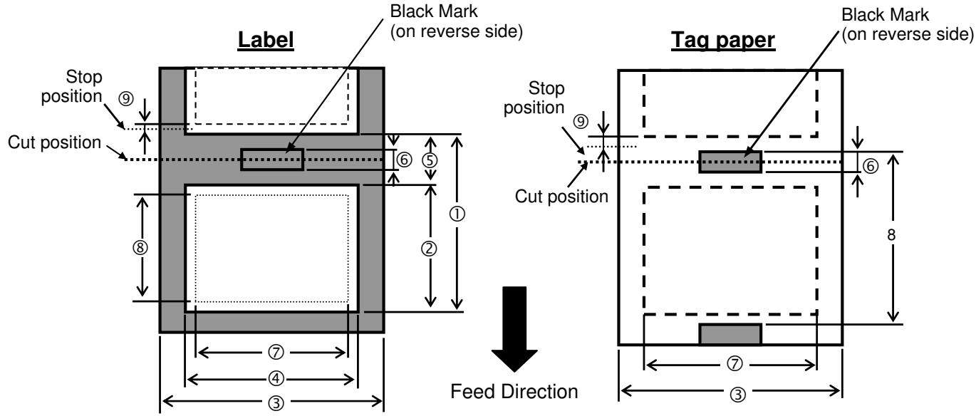
Paper Size and Shape
| Item | LE840 | LE850 | |||||||
| Thermal head density | 8dots/mm(203dpi) | 11.8dots/mm(300dpi) | |||||||
| Thermal head width | 104.0mm | 108.416mm | |||||||
| Contents | Issue type | Batch | Strip *Note1 | Disc Cutter | Batch | Strip *Note1 | Disc Cutter | ||
| 1. | Paper Pitch | Label | Min. | 10.0 | 15.0 | 25.0 | 10.0 | 15.0 | 25.0 |
| Max. | 1500.0 | 1500.0 | 1500.0 | 1500.0 | 1500.0 | 1500.0 | |||
| Tag | Min. | 10.0 | - | 25.0 | 10.0 | - | 25.0 | ||
| Max. | 1500.0 | - | 1500.0 | 1500.0 | - | 1500.0 | |||
| 2. | Paper length | Min. | 8.0 | 13.0 | 19.0 *Note2 | 8.0 | 13.0 | 19.0 *Note2 | |
| Max. | 1498.0 | 1498.0 | 1494.0 | 1498.0 | 1498.0 | 1494.0 | |||
| 3. | Tag width and Backing paper width | Min. | Direct | 25.0 | 25.0 | ||||
| Transfer | 45.0 | 45.0 | |||||||
| Max. | Direct | 114.0 | 114.0 | ||||||
| Transfer | 107.0 | 107.0 | |||||||
| 4. | Label width | Min. | Direct | 22.0 | 22.0 | ||||
| Transfer | 42.0 | 42.0 | |||||||
| Max. | Direct | 111.0 | 111.0 | ||||||
| Transfer | 104.0 | 104.0 | |||||||
| 5. | Label-to-label gap | Min. | 2.0 | 6.0 | 2.0 | 6.0 | |||
| Max. | 20.0 | 20.0 | |||||||
| 6. | Black mark length | Min. | 2.0 | 2.0 | |||||
| Max. | 10.0 | 10.0 | |||||||
| 7. | Max. effective print width | Max. | 104.0 +/-0.2 | 104.0 +/-0.2 | |||||
| 8. | Effective print length | Label | Min. | 6.0 | 15.0 | 17.0 | 6.0 | 15.0 | 17.0 |
| Max. | 1496.0 | 1496.0 | 1492.0 | 1496.0 | 1496.0 | 1492.0 | |||
| Tag | Min. | 8.0 | - | 19.0 | 8.0 | - | 21.4 | ||
| Max. | 1498.0 | - | 1498.0 | 1498.0 | - | 1498.0 | |||
| 9. | Slow-up and down area(Un-print area) | Slow-up | 1.0 | 1.0 | |||||
| Slow-down | 1.0 | 1.0 | |||||||
| 10. | Paper thickness | Min. | 0.13 | 0.13 | |||||
| Max. | 0.17 | 0.17 | |||||||
| 11. | Paper thicknesscan be cut | Min. | - | 0.08(Liner) | - | 0.08(Liner) | |||
| Max. | - | 0.17 | - | 0.17 | |||||
| 12. | Max. paper roll diameter | φ200(when the built in rewind is used φ180) | φ200(when the built in rewind is used φ180) | ||||||
| 13. | Paper winding direction | Inside the printing sideOutside the printing side | Inside the printing sideOutside the printing side | ||||||
| 14. | Paper core | Inside diameterφ76.2±0.3 | Inside diameterφ76.2±0.3 | ||||||
| 15 | Ribbon width | 68-112mm | 68-112mm | ||||||
NOTES:
- To ensure print quality and print head life use only Oki Data specified media.
-
When using the peel-off at 12''/sec or more for 203dpi model, issue at 10''/sec . When using the peel-off at 10''/sec or more for 300dpi model, issue at 8''/sec .
-
When using the disk cutter, the label length must meet the following condition: Label length 18.0mm - (Gap length/2).
- The Strip Module do not support the print speed of 10''/sec . or faster.
- The ratio of a label length to a gap length must be a minimum of 3 to 1 (3:1).
- When using label stock in cut mode, be sure to cut in the gaps. Cutting labels will cause the adhesive to stick to the cutter, which may affect the cutter performance and shorten the cutter life.
- When the Strip Module is used on the LE840 (203 dpi model), the print speed is automatically corrected to 10"/sec. if 12"/sec. or faster is specified.
When the Strip Module is used on the LE850 (300 dpi model), the print speed is automatically corrected to 8"/sec. if 8"/sec. or faster is specified.
7.1.2 Detection Area of the Transmissive Sensor (Gap sensor)
Sensor position
The sensor is movable in the range from the center of the paper to the left end.
Transmissive sensor and Reflective sensor (Black mark sensor) are moving from side to side at same time each sensor unit.
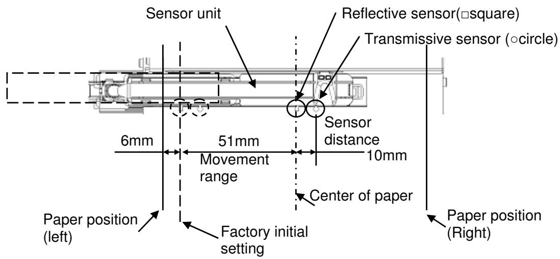
Detection Area of Transmissive Sensor
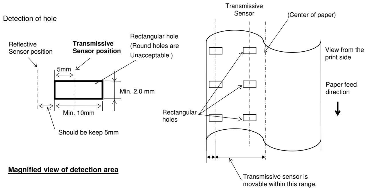
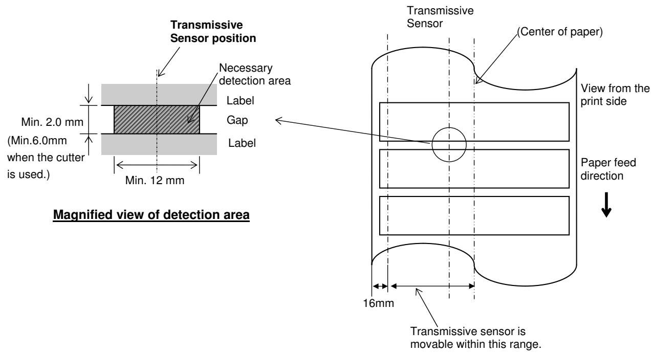
7.1.3 Detection Area of the Reflective Sensor (Black mark sensor)
The Reflective Sensor is movable from the centre to the left edge of media.
The reflection factor of the Black Mark must be 10% or lower with a waveform length of 950 nm.
The Reflective Sensor should be aligned with the centre of the Black Mark.
The black marks, if necessary, must be printed on the labels in the gap areas.
Rectangular holes can substitute the black marks, on the condition that nothing is printed on the back side.
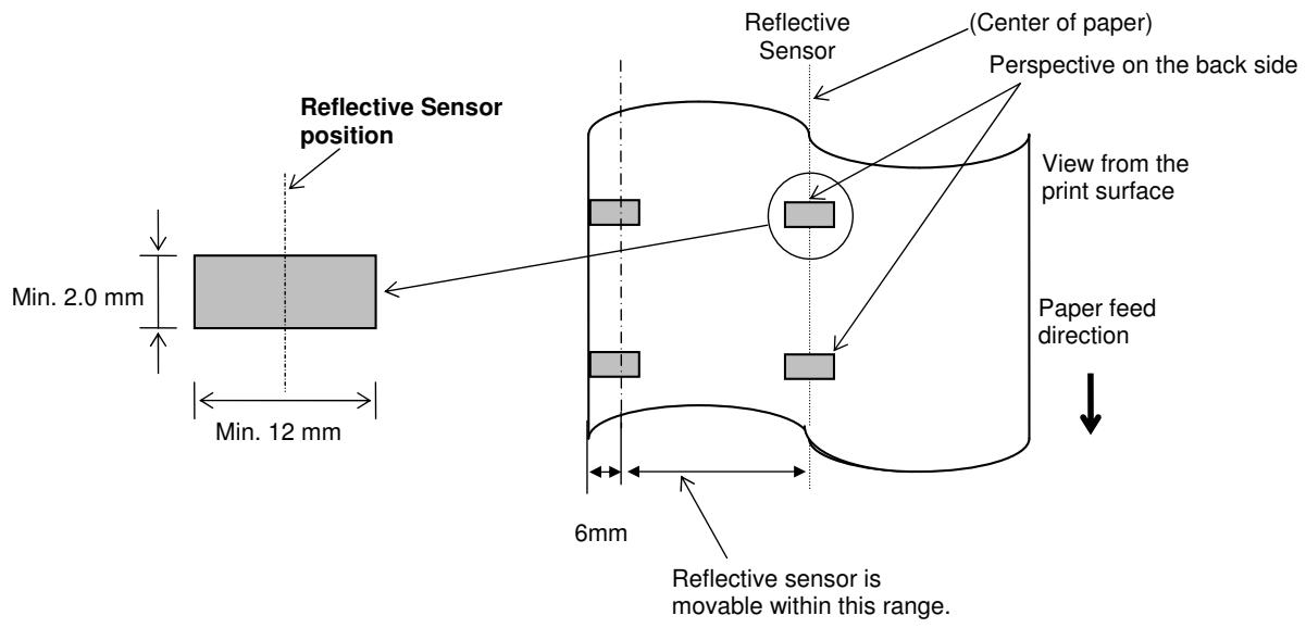
7.1.4 Effective Print Area
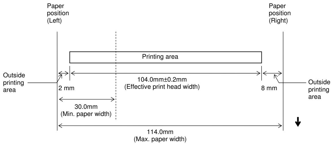
7.1.4.1 Relationship between Print Head Effective Print Width and Paper Width
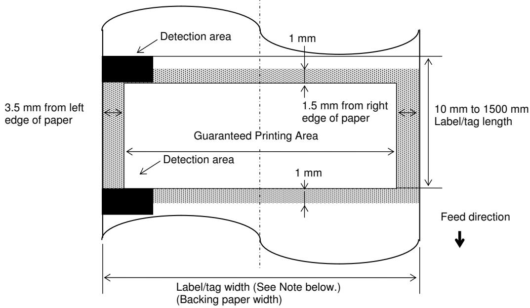
7.1.4.2 Effective Print Area of Tags and Labels
NOTES:
- Print quality in the shaded area is not guaranteed. For the label, printing in the 1-mm width area around the label is not guaranteed as well as the shaded area shown above.
- This printer paper set position is left side, The center of the paper (label and tag) is not almost aligned with the center of the print head.
- If printing is performed in the shaded area, the ribbon may wrinkle. This may affect the print quality of the guaranteed printing area.
7.1.5 RFID Tags
Available RFID tag types are different depending on the RFID modules/printers.
Cautions for using RFID Tags
(1) Lift-up of Print Head
An RFID tag chip or the print head may be damaged when the print head passes over the chip.
(2) Storage of RFID Supplies
Do not store RFID tags close to printers, as their read/write performance may be compromised when they are used.
(3) Roll-type RFID Supplies
When RFID supplies are to be rolled, roll hardness must be considered.
Although it depends on the type of adhesive, tag, and backing paper, RFID-tag embedded labels tend to stay rolled. Especially, when they are outside wound, a paper jam error may occur. Unless otherwise specified, it is recommended that the RFID-tag embedded labels be inside wound.
(4) Sensor
When the transmissive sensor or reflective sensor is enabled, transmittance or reflectivity of a label or tag may vary at an RFID-tag embedded area depending on the pattern of the antenna or other factors. In such cases, a manual threshold setting is required. For details, refer to Section 2.10 Threshold Setting.
(5) Cutter
When an RFID label or tag is used in cut issue mode, care must be taken not to cut the antenna of the RFID tag or the IC chip so as not to damage the cutter.
(6) Static Electricity
When printing is performed in a place where humidity is low or under some specific conditions, writing data on an RFID tag may fail due to static electricity generated by the label or ribbon.
(7) Printing on Bump (Chip/Antenna) Area
Embedding an RFID tag in labels creates bumps on the label surface, causing incomplete printing.
Uneven printing or incomplete printing can occur easily, especially within 5mm top and bottom, and to the left and right sides of the RFID-tag embedded area, as shown in the figure below.
NOTE: The degree of poor printing quality differs depending on height of a chip/antenna used.
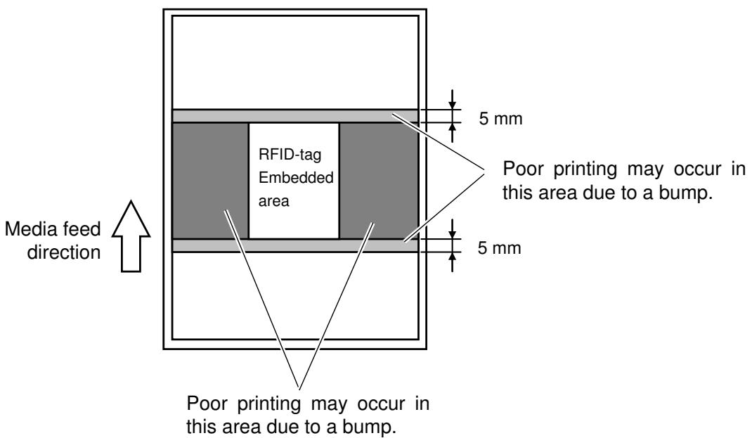
(8) Ambient Temperature
As low temperatures cause wireless performance to deteriorate, writing data on an RFID tag may fail under such conditions.
(9) Strip Issue
Stripping performance in strip issue mode depends on the type of adhesive, tag, and backing paper. For some RFID supplies used, a strip issue may not be performed properly.
(10) Caution for Minimum Label Pitch Length
When using media, with a short label pitch length, data may be written on an RFID tag adjacent to the target RFID tag.
As the location, where data is to be written, differs among RFID tag types, a check must be performed to make sure that the data is written on the target RFID tags. For details, please contact the nearest Oki Data support representative.
(11) Defective RFID Supply
RFID supplies may include defective RFID tags at the time of shipment from the maker. The defect rate differs depending on tag types, method of converting to supplies, etc.
The RFID supply manufacturer should provide a way to identify defective tags by printing a mark on them or any other methods.
Or, defective tags should be rejected in the production process.
The end users must be notified on how to identify a defective tag from a good one.
7.2 Ribbon
The approved ribbon must be used.
Use of any non-approved ribbon may cause problems.
A. SHAPE AND SIZE OF RIBBON
| No. | Item | Specification | |
| 1 | Ribbon Shape | Spool type | |
| 2 | Ribbon Width | 68(40) ±1 mm to 112 mm | |
| Ribbon Winding Width | 68(40) ±2 mm to 112 mm | ||
| 3 | Max. Ribbon Length | 600 m (Ø90 mm or less) | |
| 4 | Max. Ribbon OD | Outside wound | Ø90 mm |
| Inside wound | Ø80 mm | ||
| 5 | Back Treatment | Coated | |
| 6 | Ribbon Core | Material | Paper |
| Shape | See Fig. 1. | ||
| 7 | Leader Tape | Polyester film (silver), 300 ± 5 mm long | |
| 8 | End Tape | Polyester film (silver), 250 ± 5 mm long | |
| 9 | Winding Method | The ribbon is wound outside. For the core and ribbon winding positions, see Fig. 2. | |
NOTES:
- The ribbon type number and the lot No. should be marked on the ribbon core end with black indelible ink. (If doing this is impossible, separately specify the location where the type number and the lot number are stamped.)
-
It is recommended that the ribbon is wider than the paper width by 5 mm or more.
-
When the difference between the ribbon width and the paper width is same or too minimum, the ribbon may wrinkle.
- When the difference between the ribbon width and the paper width is too large, the ribbon may wrinkle.
-
Be careful of the upper limit of the ribbon width.
-
The ribbon which is narrower than the paper width by 5 mm or more can be used, but the print area becomes narrower.
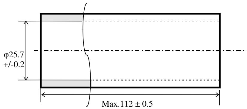
Fig. 1 Core Shape
Fig. 2 Positional Relationship between Core and Ribbon
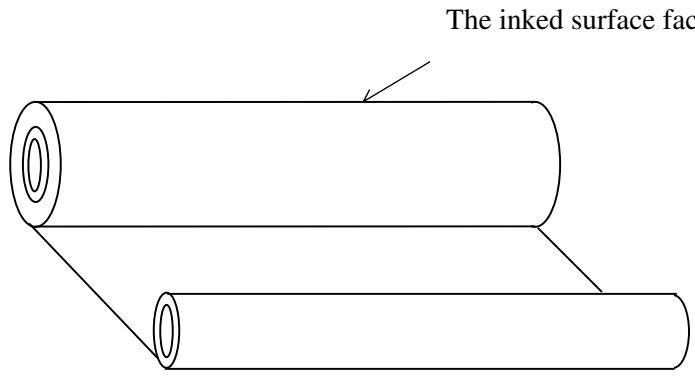
NOTE: Wind the ink ribbon so that the ribbon center aligns with the core center.
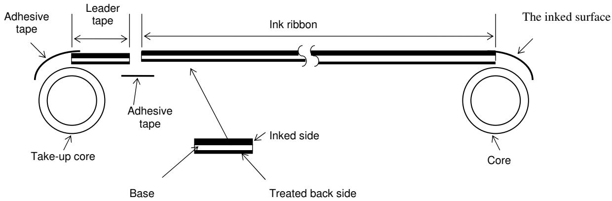
Fig. 3: Connection between Leader Tape and Ribbon
NOTES on using ribbon:
If the difference between the ribbon width and the paper width is too large, the ribbon may wrinkle. Refer to the table below and choose the paper appropriate to the ribbon width. Even if the ribbon is narrower than paper, printing can be performed. However, it results in the narrower print range.
LE840T/LE850T
| Ribbon width | 68mm | 84mm | 112mm |
| Appropriate paper width | 45 to 63 mm | 63 to 79 mm | 79 to 107 mm |
The ribbon tension adjustment may be further required according to the ribbon width. In the case a narrower width of the ribbon is used, if the ribbon tension is strong, the ribbon will wrinkle. According to the print patterns, fine adjustment of the ribbon take-up motor is required. As a guide, regardless of the print speed, it should be set to “-3” (FW) and “-1” (BK) for 68-mm wide ribbon, and “-4” (FW) and “-2” (BK) for 50-mm wide or less ribbon, respectively.
7.3 Recommended Media and Ribbon Types
APPROVED PAPER
| Type | Item Code | Manufacturer Type No. | Paper Thickness (μm) | Manufacturer | Remarks | |
| Label | Direct thermal type | 150LA-1P | 82 | RICOH | ||
| Thermal transfer type | Vellum | Raflatac | (Uncoated) | |||
| Transtherm 1C | Fasson | (Coated, gloss) | ||||
| VES-85 | 85 | OSAKA SEALING PRINTING | (Yupo) | |||
| FR1412-50 | White PET | 50 | LINTEC | |||
| FR1615-50 | Silver chemical mat | 50 | LINTEC | |||
| Tag | Direct thermal type | 130LAB-1-150 | 150 | RICOH | T.B.D | |
| Thermal transfer type | IS50 | I-BEST S | 164 | OSAKA SEALING PRINTING | ||
NOTE:
- The print head life varies depending on the print pattern (printing ratio).
- Transmissive sensor (Gap sensor) is initially adjusted with Vellum label, and the Reflective sensor (Black mark sensor) is adjusted with I-BEST S tag. When using other Label/Tag, it may be necessary to adjust sensor. When occurring Feed Error, adjust sensor with using Label/Tag. For details regarding the sensor adjustment, refer to Section 2.11 Sensor Setting.
APPROVED RIBBONS
Type: W: Wax SR: Semi-resin R: Resin
| Item Code(Global) | Manufacturer Ink Name | Base Thickness(μm) | Manufacturer | Type | Remarks | Applicable models (indicated with O) | ||
| G | T | H | ||||||
| 1 | AWR6 | 4.5 | ARMOR | W | O | O | ||
| 2 | AWX-FH | 4.5 | ARMOR | W | O | O | ||
| 3 | AWARD | 4.5 | ARMOR | W | O | O | ||
| 4 | AWR470Solfree | 4.5 | ARMOR | W | O | O | ||
| 5 | APR6 | 4.5 | ARMOR | SR | O | O | ||
| 6 | APX-FH | 4.5 | ARMOR | SR | O | O | ||
| 7 | AXR7+ | 4.5 | ARMOR | R | O | O | O | |
| 8 | AXR8 | 4.5 | ARMOR | R | O | O | O | |
| 9 | B110A | 4.5 | RICOH | SR | O | O | ||
| 10 | B110AXS | 4.5 | RICOH | SR | O | O | ||
| 11 | B110C | 4.5 | RICOH | R | O | O | O | |
| 12 | B110CR | 4.5 | RICOH | R | O | O | O | |
| 13 | TR4085 | 4.5 | DNP | W | O | O | ||
| 14 | TR5080 | 4.5 | DNP | SR | O | O | ||
| 15 | M280 | 4.5 | DNP | SR | O | O | ||
| 16 | R510HF | 4.5 | DNP | R | O | O | O | |
| 17 | R300 | 4.5 | DNP | R | O | O | O | |
NOTE:
- Print conditions and paper to be used may differ for each ribbon.
PRINT TONE FINE ADJUSTMENT VALUES BY SUPPLIES
For 203dpi model
| Print Mode | Ribbon | Paper | Print speed | Print energy type | Remarks | |||
| 3"/s | 6"/s | 10"/s | 12"/s | |||||
| Thermal transfer type | 1 | Vellum | -2 | -2 | -2 | +2 | Wax1 | This combination is not acceptable in the case of 10, 12ips and high temperature environment. |
| TT1C | 0 | 0 | +2 | +2 | Wax1 | In the case of 10, 12ips and low temperature environment requires a print tone adjustment to positive direction. | ||
| I-BEST S | -2 | 0 | +4 | +6 | Wax1 | Serial bar code printed at 12ips is unusable. | ||
| 3 | Vellum | -4 | -4 | 0 | +2 | Wax1 | In the case of 3, 6ips and high temperature environment requires a print tone adjustment to negative direction. | |
| TT1C | -6 | -4 | +2 | +4 | Wax1 | |||
| I-BEST S | -4 | -4 | +2 | +4 | Wax1 | |||
| 4 | Vellum | -8 | -4 | +2 | unusable | Wax1 | In the case of 3, 6ips and high temperature environment requires a print tone adjustment to negative direction. This combination is not acceptable in the case of 10ips and high temperature environment. | |
| TT1C | -6 | -4 | +6 | +6 | Wax1 | In the case of 3, 6ips and high temperature environment requires a print tone adjustment to negative direction. | ||
| I-BEST S | -4 | -2 | unusable | Wax1 | In the case of 3ips and high temperature environment requires a print tone adjustment to negative direction. | |||
| 5 | Vellum | 0 | 0 | +4 | +6 | Semi-resin1 | In the case of 6ips and low temperature environment requires a print tone adjustment to positive direction. This combination is not acceptable in the case of 10, 12ips and high temperature environment. | |
| TT1C | +2 | +4 | +6 | unusable | Semi-resin1 | |||
| VES-85 | -4 | T.B.D | +2 | +2 | Semi-resin1 | |||
| I-BEST S | 0 | 0 | +4 | unusable | Semi-resin1 | |||
| Thermal transfer type | 7 | FR1412-50 | +6 | +4 | unusable | Resin1 | ||
| FR1615-50 | +2 | +2 | unusable | Resin1 | ||||
| 13 | Vellum | -4 | -6 | 0 | +2 | Wax1 | This combination is not acceptable in the case of all print speed and high temperature environment. | |
| TT1C | -4 | -2 | +4 | +6 | Wax1 | |||
| I-BEST S | 0 | 0 | +4 | unusable | Wax1 | |||
| Direct thermal type | 150LA-1P | 0 | 0 | 0 | 0 | Standard | ||
| 130LAB-1-150 | +2 | +2 | +6 | +6 | Standard | |||
NOTES:
1: Since the print tones provided in the above table are the recommended values, the variance should be taken into consideration when in use.
2: The print energy type must be set the above table by all means. For setting method of the print energy type, refer to Section 2.6.2.2 Software Set.
*3: It limits print tone fine adjustment for the protection of thermal head by the rating of the maximum supply energy of thermal head. The tone of printing do not thicken even if it is set print tone fine adjustment value more than the value of the list shown below.
| Print energy type | Print tone fine adjustment limit | |||
| 3"/s | 6"/s | 10"/s | 12"/s | |
| Standard | +10 | +10 | +10 | +6 |
| Wax1 | +10 | +10 | +3 | -1 |
| Wax2 | +10 | +10 | +3 | -1 |
| Semi-resin1 | +10 | +10 | +10 | +3 |
| Semi-resin2 | +10 | +10 | +3 | -1 |
| Resin1 | +10 | +10 | +4 | -1 |
| Wax3 | +10 | +10 | -1 | -1 |
| Semi-resin3 | +10 | +10 | +3 | -1 |
| Resin2 | +10 | +5 | 0 | -1 |
For 300dpi model
| Print Mode | Ribbon | Paper | Print speed | Print energy type | Remarks | ||||
| 3"′/s | 5"′/s | 8"′/s | 10"′/s | 12"′/s | |||||
| Thermal transfer type | 1 | Vellum | +4 | 0 | +4 | +6 | Unusable | Wax1 | In the case of 3, 5, 8ips and high temperature environment requires a print tone adjustment to negative direction. |
| TT1C | +4 | +2 | +6 | Unusable | Wax1 | In the case of 8ips and low temperature environment requires a print tone adjustment to positive direction.In the case of 8ips and high temperature environment requires a print tone adjustment to negative direction. | |||
| I-BEST S | Unusable | Wax1 | |||||||
| 3 | Vellum | -4 | -2 | +6 | Unusable | Wax1 | In the case of 3, 5, 8ips and high temperature environment requires a print tone adjustment to negative direction. | ||
| TT1C | -2 | -2 | 0 | 0 | Unusable | Wax1 | In the case of 3, 5ips and high temperature environment requires a print tone adjustment to negative direction. | ||
| I-BEST S | -2 | 0 | +2 | +2 | Unusable | Wax1 | In the case of 3ips and high temperature environment requires a print tone adjustment to negative direction. | ||
| 4 | Vellum | Unusable | Wax1 | ||||||
| TT1C | 0 | 0 | +2 | +2 | Unusable | Wax1 | |||
| I-BEST S | Unusable | Wax1 | |||||||
| 5 | Vellum | +2 | +2 | +4 | +6 | Unusable | Semi-resin1 | ||
| TT1C | +2 | +4 | +6 | +6 | Unusable | Semi-resin1 | |||
| VES-85 | -2 | 0 | -2 | -2 | 0 | Semi-resin1 | |||
| I-BEST S | 0 | +4 | +4 | +4 | Unusable | Semi-resin1 | |||
| 7 | FR1412-50 | 0 | +4 | +6 | Unusable | Resin1 | |||
| FR1615-50 | +2 | +4 | +6 | Unusable | Resin1 | ||||
| 13 | Vellum | +4 | +4 | +4 | Unusable | Wax1 | In the case of 3, 5, 8ips and high temperature environment requires a print tone adjustment to negative direction. | ||
| TT1C | +2 | +4 | +4 | +4 | Unusable | Wax1 | |||
| I-BEST S | Unusable | Wax1 | |||||||
| 3"/s | 5"/s | 8"/s | 10"/s | 12"/s | |||||
| Direct Thermal type | 150LA-1P | 0 | 0 | 0 | 0 | 0 | Standard | ||
| 130LAB-1-150 | +2 | +4 | +6 | Unusable | Unusable | Standard | |||
NOTES:
1: Since the print tones provided in the above table are the recommended values, the variance should be taken into consideration when in use.
2: The print energy type must be set the above table by all means. For setting method of the print energy type, refer to the Key Operation Manual.
*3: It limits print tone fine adjustment for the protection of thermal head by the rating of the maximum supply energy of thermal head. The tone of printing do not thicken even if it is set print tone fine adjustment value more than the value of the list shown below.
| FEAAPrint energy type | Print tone fine adjustment limit | ||||
| 3"/s | 5"/s | 8"/s | 10"/s | 12"/s | |
| Standard | +10 | +10 | +10 | +10 | +6 |
| Wax1 | +10 | +10 | +9 | +2 | -4 |
| Wax2 | +10 | +10 | +9 | +2 | -4 |
| Semi-resin1 | +10 | +10 | +10 | +8 | 0 |
| Semi-resin2 | +10 | +10 | +8 | +1 | -5 |
| Resin1 | +10 | +10 | +10 | +4 | 0 |
| Wax3 | +10 | +10 | +3 | -3 | -2 |
| Semi-resin3 | +10 | +10 | +3 | -2 | 0 |
| Resin2 | +10 | +10 | 0 | -2 | 0 |
7.4 Care/Handling of Media and Ribbon
CAUTION!
Be sure to carefully review and understand the Supply Manual. Use only media and ribbons that meet specified requirements. Use of non-specified media and ribbons may shorten the head life and result in problems with bar code readability or print quality. All media and ribbons should be handled with care to avoid any damage to the media, ribbons or printer. Read the guidelines in this section carefully.
- Do not store the media or ribbon for longer than the manufacturer's recommended shelf life.
- Store media rolls on the flat end. Do not store them on the curved sides as this might flatten that side causing erratic media advance and poor print quality.
- Store the media in plastic bags and always reseal after opening. Unprotected media can get dirty and the extra abrasion from the dust and dirt particles will shorten the print head life.
- Store the media and ribbon in a cool, dry place. Avoid areas where they would be exposed to direct sunlight, high temperature, high humidity, dust or gas.
- The thermal paper used for direct thermal printing must not have specifications which exceed Na^+ 800 ppm , K^+ 250 ppm and Cl^- 500 ppm .
- Some ink used on pre-printed media may contain ingredients which shorten the print head's product life. Do not use labels pre-printed with ink which contain hard substances such as carbonic calcium (CaCO3) and kaolin (Al2 O3, 2 SiO2, 2 H_2 O) .
For further information, please contact your local distributor or your media and ribbon manufacturers.
APPENDIX 1 MESSAGES AND LEDs
Appendix 1 describes the LCD messages displayed on the operation panel.
Symbols in the message
1: O: The LED is illuminated. : The LED is flashing. : The LED is unlit.
2:%%,%%,%%: Remaining memory size of the external memory: 0 to 09,999,999 (in K bytes)
3: ###: Remaining memory size for PC commands storage area in the internal memory: 0 to 3072 (in K bytes)
4: &&&&: Remaining memory size for writable characters storage area: 0 to 3147 (in K bytes)
| No. | LCD Message | LED Indication | Printer Status | Restoration by START key Yes/No | Acceptance of Status Request/ Reset Command Yes/No | |
| ONLINE | ERROR | |||||
| 1 | ON LINE | ○ | ● | In online mode | ----- | Yes |
| ON LINE | ⊙ | ● | In online mode (The printer is communicating) | ----- | Yes | |
| 2 | HEAD OPEN | ● | ● | The print head block is open in online mode. | ----- | Yes |
| 3 | PAUSE | ● | ● | The printer is paused. | Yes | Yes |
| 4 | COMMS ERROR | ● | ○ | A parity, overrun, or framing error has occurred during communication through the RS-232C. | Yes | Yes |
| 5 | PAPER JAM | ● | ○ | The media is jammed during paper feed. | Yes | Yes |
| 6 | CUTTER ERROR | ● | ○ | A problem has occurred with the cutter module. | Yes | Yes |
| 7 | NO PAPER | ● | ○ | The media has run out, or the media is not loaded properly. | Yes | Yes |
| 8 | NO RIBBON | ● | ○ | The ribbon has run out. | Yes | Yes |
| 9 | HEAD OPEN | ● | ○ | Feed or printing was attempted with the print head block open. | Yes | Yes |
| 10 | HEAD ERROR | ● | ○ | There is a problem with the print head. | Yes | Yes |
| 11 | EXCESS HEAD TEMP | ● | ○ | The print head has overheated. | No | Yes |
| 12 | RIBBON ERROR | ● | ○ | The ribbon has been torn. A problem has occurred with the sensor that determines the torque for the ribbon motor. | Yes | Yes |
| 13 | REWIND FULL | ● | ○ | An overflow error has occurred in the rewind unit. | Yes | Yes |
| 14 | SAVING#####KB&&&&&KB or SAVING%,%%%.%%%KB | ○ | ● | Writable character or PC command save mode | ----- | Yes |
| 15 | FORMAT#####KB&&&&&KB or FORMAT%,%%%.%%%KB | ○ | ● | The storage area is being initialised. | ----- | Yes |
| 16 | NOW LOADING... | ○ | ● | TrueType font or BASIC program is being downloaded. | ----- | Yes |
| 17 | MEMORY WRITE ERR. | ● | ○ | An error has occurred while writing to flash memory or USB memory. | No | Yes |
| 18 | FORMAT ERROR | ● | ○ | An erase error has occurred while formatting the flash memory or USB memory. | No | Yes |
| 19 | MEMORY FULL | ● | ○ | Data cannot be stored because the flash memory or USB memory is full. | No | Yes |
| 20 | Display of error message (See Notes.) | ● | ○ | A command error has occurred while analyzing the command. | Yes | Yes |
| 21 | POWER FAILURE | ● | ○ | A power failure has occurred. | No | No |
| 22 | EEPROM ERROR | ● | ○ | Data cannot be read from/written to a backup EEPROM properly | No | No |
| 23 | SYSTEM ERROR | ● | ○ | When the following abnormal operations are performed, a system error occurs:(a) Command fetch from an incorrect address.(b) Access to word data at an incorrect address.(c) Access to long-word data at an incorrect address.(d) Access to the area of 80000000H to FFFFFFFH in the logic space in user mode.(e) An undefined instruction in an area other than a delay slot was decoded.(f) An undefined instruction in a delay slot was decoded.(g) An instruction to rewrite a delay slot was decoded. | No | No |
| 24 | DHCP CLIENT INIT... | ● | ● | DHCP Client is being initialised. (Only when the DHCP is enabled.) | ----- | ----- |
| 25 | RFID WRITE ERROR | ● | ○ | The printer did not succeed in writing data onto an RFID tag after having retracted the specified number of times. | Yes | Yes |
| 26 | RFID ERROR | ● | ○ | The printer cannot communicate with the RFID module. | No | Yes |
| 27 | LOW BATTERY | ● | ○ | The voltage of the Real Time Clock Battery is low. | No | Yes |
| 28 | INPUT PASSWORD | ● | ● | The printer is waiting for a password to be entered. | No | No |
| 29 | DATABASE INVALID Please Power OFF | ● | ● | A wrong password was entered three consecutive times. | No | No |
| 30 | INTERNAL COM ERR | ● | ● | A hard error occurred in internal serial interface. | No | No |
NOTE: When an error message listed above appears on the LCD display please refer to Section 5 TROUBLESHOOTING for a solution.
NOTES:
- If an error is found in a command received, up to 42 bytes of the erroneous command, starting from the command code, will be displayed. (However, [LF] and [NUL] will not be displayed.)
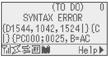
Example 1
[ESC]PC001;0\u0,0300,2,2,A,00,B[LF][NUL]
Command error
The following message appears.
SYNTAX ERROR
PC001;0A00,0300,2,2,A
,00,B
Example 2
[ESC]T20G30[LF] [NUL]
Command error
The following message appears.
SYNTAXERROR
T20G30
Example 3
[ESC]PC002;0100,0300,15,15,A,00,00,J0101,+000000000\uA,Z10,P1[LF] [NUL]
Command error
The following message appears.
SYNTAXERROR
PC002;0100,0300,15,15
,A,00,00,J0101,+00000
- When the error is shown, “? (3FH)” appears for character codes other than 20H to 7FH and A0H to DFH.
- For details, please refer to the LE840/LE850 External Equipment Interface Manual
APPENDIX 2 INTERFACE
NOTE:
To prevent radiation and reception of electrical noise, the interface cables must meet the following requirements:
- In case of a parallel interface cable or serial interface cable, fully shielded and fitted with metal or metallised connector housings.
- Keep as short as possible.
- Should not be bundled tightly with power cords.
- Should not be tied to power line conduits.
- A parallel interface cable to be used should conform to IEEE1284.
USB interface (Standard)
Physical Layer:
Conforming to V2.0 Full speed
Transfer type:
Control transfer, Bulk transfer
Transfer rate:
Full speed (12M bps)
Class:
Printer class
Number of ports:
1
Power source:
Self power
Connector:
Type B
| Pin No. | Signal |
| 1 | VCC |
| 2 | D- |
| 3 | D+ |
| 4 | GND |

Series B Plug
LAN (Standard: Available for only Ethernet model)
Physical Layer:
IEEE802.3 10BASE-T/100BASE-TX
Number of ports: 1
Connector: RJ-45
LED status: Link LED, Activity LED
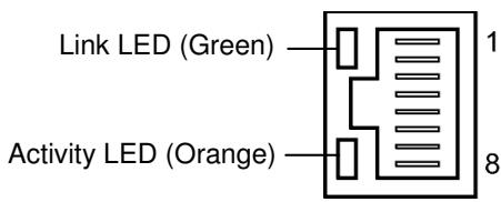
| LED | LED Status | LAN status |
| Link | ON | 10Mbps link or 100Mbps link is detected. |
| OFF | No link is detected. * Communication cannot be made while the Link LED is off. | |
| Activity | ON | Communicating |
| OFF | Idle |
LAN cable:
10BASE-T: UTP category 3 or category 5
100BASE-TX: UTP category 5
Cable length:
Segment length Max. 100m
NOTE:
When a generally-used twisted pair Ethernet (TPE) or UTP cable is used, a communication error may occur depending on your operating environment. In such case, you may be requested to use a shielded twisted pair cable.
Serial interface (Option)
Type: RS-232C
Communication mode: Full duplex
Transmission speed: 2400 bps, 4800 bps, 9600 bps, 19200 bps, 38400 bps, 115200 bps
Synchronization: Start-stop synchronization
Start bit: 1 bit
Stop bit 1 bit, 2 bit
Data length: 7 bit, 8 bit
Parity: None, EVEN, ODD
Error detection: Parity error, Framing error, Overrun error
Protocol: Unprocedure communication
Data input code: ASCII code, European character 8 bit code, graphic 8 bit code, JIS8 code, Shift JIS Kanji code, JIS Kanji code
Receive buffer: 1M byte
Connector:
| Pin No. | Signal |
| 1 | N.C |
| 2 | TXD (Transmit Data) |
| 3 | RXD (Received Data) |
| 4 | DSR (Data Set Ready) |
| 5 | SG (Signal Ground) |
| 6 | DTR (Data Terminal Ready) |
| 7 | CTS (Clear to Send) |
| 8 | RTS (Request to Send) |
| 9 | N.C |
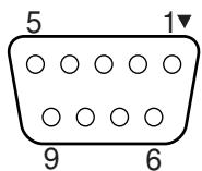
Parallel interface (Centronics) (Option)
Mode: Conforming to IEEE1284
Compatible mode (SPP mode), Nibble mode
Data input method: 8 bit parallel
Control signal:
| SPP Mode | Nibble Mode | ECP Mode |
| nStrobe | Host_clk | Host_clk |
| nAck | Ptr_clk | Periph_clk |
| Busy | PtrBusy | PeriphAck |
| Perror | AckDataReq | NAckReverse |
| Select | Xflag | Xflag |
| nAutoFd | HostBusy | HostAck |
| nInit | nInit | nReverseRequest |
| nFault | nDataAvail | nPeriphRequest |
| nSelectIn | IEEE1284Active | IEEE1284Active |
Data input code: ASCII code
European 8 bit code
Graphic 8 bit code
JIS8 code
Shift JIS Kanji code
JIS Kanji code
Receive buffer: 1MB
Connector:
| PIN No. | Signal | ||
| SPP Mode | Nibble Mode | ECP Mode | |
| 1 | nStrobe | Host_clk | Host_clk |
| 2 | Data 1 | Data 1 | Data 1 |
| 3 | Data 2 | Data 2 | Data 2 |
| 4 | Data 3 | Data 3 | Data 3 |
| 5 | Data 4 | Data 4 | Data 4 |
| 6 | Data 5 | Data 5 | Data 5 |
| 7 | Data 6 | Data 6 | Data 6 |
| 8 | Data 7 | Data 7 | Data 7 |
| 9 | Data 8 | Data 8 | Data 8 |
| 10 | nAck | Ptr_clk | Periph_clk |
| 11 | Busy | PtrBusy | PeriphAck |
| 12 | PError | AckDataReq | nAckReverse |
| 13 | Select | Xflag | XFlag |
| 14 | nAutoFd | HostBusy | HstAck |
| 15 | NC | NC | NC |
| 16 | 0V | 0V | 0V |
| 17 | CHASSIS GND | CHASSIS GND | CHASSIS GND |
| 18 | +5V (For detection) | +5V (For detection) | +5V (For detection) |
| 19 | TWISTED PAIR GND(PIN1) | TWISTED PAIR GND(PIN1) | TWISTED PAIR GND(PIN1) |
| 20 | TWISTED PAIR GND(PIN2) | TWISTED PAIR GND(PIN2) | TWISTED PAIR GND(PIN2) |
| 21 | TWISTED PAIR GND(PIN3) | TWISTED PAIR GND(PIN3) | TWISTED PAIR GND(PIN3) |
| 22 | TWISTED PAIR GND(PIN4) | TWISTED PAIR GND(PIN4) | TWISTED PAIR GND(PIN4) |
| 23 | TWISTED PAIR GND(PIN5) | TWISTED PAIR GND(PIN5) | TWISTED PAIR GND(PIN5) |
| 24 | TWISTED PAIR GND(PIN6) | TWISTED PAIR GND(PIN6) | TWISTED PAIR GND(PIN6) |
| 25 | TWISTED PAIR GND(PIN7) | TWISTED PAIR GND(PIN7) | TWISTED PAIR GND(PIN7) |
| 26 | TWISTED PAIR GND(PIN8) | TWISTED PAIR GND(PIN8) | TWISTED PAIR GND(PIN8) |
| 27 | TWISTED PAIR GND(PIN9) | TWISTED PAIR GND(PIN9) | TWISTED PAIR GND(PIN9) |
| 28 | TWISTED PAIR GND(PIN10) | TWISTED PAIR GND(PIN10) | TWISTED PAIR GND(PIN10) |
| 29 | TWISTED PAIR GND(PIN11) | TWISTED PAIR GND(PIN11) | TWISTED PAIR GND(PIN11) |
| 30 | TWISTED PAIR GND(PIN31) | TWISTED PAIR GND(PIN31) | TWISTED PAIR GND(PIN31) |
| 31 | nInit | nInit | nReverseRequest |
| 32 | nFault | NDataAvail | nPeriphRequest |
| 33 | 0V | 0V | 0V |
| 34 | NC | NC | NC |
| 35 | NC | NC | NC |
| 36 | nSelectIn | IEEE1284Active | IEEE1284Active |
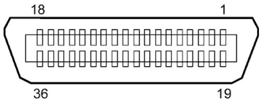
IEEE1284-B Connector
Wireless LAN (Option)
Standard: Conforming to IEEE802.11b, and IEEE802.11g
Client protocol: TCP/IP, Socket, LPD (LLPR), DHCP/WINS, HTTPD (SNMP)
Print protocol: Socket communication/LPR
Security protocol: WEP (64 bits/128 bits) or AES, TKIP (only when using WPA, WPA-PSK)
Shared key (for WEP), PSK, PEAP, TLS, TTLS, MD5, LEAP, EAP-FAST
Antenna: Built-in
Parameter setting: via USB, LAN, WLAN, RS-232C, Parallel
Default IP address: 192.168.10.21
Default subnet mask: 255.255.255.0
Certification: Wi-Fi, CCX V3, V4
NOTE:
MAC address of the Wireless LAN module will be necessary when setting the MAC address filtering function of an access point. Please ask a service person of your nearest Oki Data service representative.
USB Host interface (Option)
Physical Layer: Conforming to V2.0 Full speed
Transfer type: Control transfer, Bulk transfer
Transfer rate: Full speed (12M bps)
Number of ports: 1
Power supply: 500mA output
Connector: Type A
Expansion I/O Interface (Option)
Input Signal
IN0 to IN5
Output Signal
OUT0 to OUT6
Connector
FCN-781P024-G/P or equivalent
(External Device Side)
Connector
(Printer Side)
FCN-685J0024 or equivalent
N.C.: No Connection
| Pin | Signal | I/O | Function | Pin | Signal | I/O | Function |
| 1 | IN0 | Input | FEED | 13 | OUT6 | Output | |
| 2 | IN1 | Input | 14 | N.C. | ----- | ||
| 3 | IN2 | Input | PAUSE | 15 | COM1 | Common (Power) | |
| 4 | IN3 | Input | 16 | N.C. | ----- | ||
| 5 | IN4 | Input | 17 | N.C. | ----- | ||
| 6 | IN5 | Input | 18 | N.C. | ----- | ||
| 7 | OUT0 | Output | FEED | 19 | N.C. | ----- | |
| 8 | OUT1 | Output | 20 | N.C. | ----- | ||
| 9 | OUT2 | Output | PAUSE | 21 | COM2 | Common (Ground) | |
| 10 | OUT3 | Output | ERROR | 22 | N.C. | ----- | |
| 11 | OUT4 | Output | 23 | N.C. | ----- | ||
| 12 | OUT5 | Output | POWER ON | 24 | N.C. | ----- |
Input Circuit
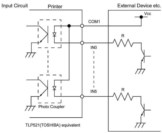
Output Circuit
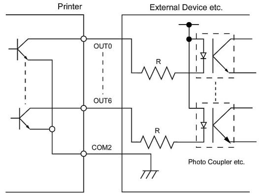
Output Circuit
RFID (Option)
Module: TagSysm MEDIO S002 /S003 (Not included in this optional kit.)
Frequency: 13.56MHz
Output: 200 mW
Available RFID tag: TagSys C210, C220, C240, C320 I-Code, Tag-it, ISO15693
Antenna: RF antenna is not included in this optional kit.
APPENDIX 3 PRINT SAMPLES
Font
Times Roman medium
< D> Times Roman bold
< E> Times Roman bold
< F> Times Roman italic
< H> Helvetica medium
< 1> Helvetica medium
< J> Helvetica bold
< L> Helvetica italic
PRESENTATION BOLD
< 0> Prestige Elite medium
Prestige Elite bold
Courier medium
Gothic 725 Black
APPENDIX 3 PRINT SAMPLES (Cont.)
Bar codes

JAN8, EAN8

Interleaved 2 of 5

NW7

UPC-E

EAN13+5 digits

CODE39 (Full ASCII)

UPC-E+2 digits

EAN8+2 digits

UPC-A

MSI

CODE39 (Standard)

JAN13, EAN13

EAN13+2 digits

CODE128

CODE93

UPC-E+5 digits

EAN8+5 digits

UPC-A+2 digits

UPC-A+5 digits

Industrial 2 of 5
Customer bar code


KIX Code

Data Matrix

QR code

MaxiCode

PDF417

UCC/EAN128

POSTNET

Customer bar code of high priority

RM4SCC

MicroQR

Micro PDF417

CP Code
- GS1 DataBar family (with no compound composite printed)

GS1 DataBar (Truncated)

GS1 DataBar Stacked Omnidirectional

GS1 DataBar Expanded Stacked

UPC-E

EAN-8

GS1 DataBar Stacked

GS1 DataBar Limited

GS1 DataBar Expanded

UPC-A

EAN-13

UCC/EAN-28 with CC-A, CC-B, or CC-C
- GS1 DataBar family (with compound composite printed)

GS1 DataBar (Truncated)

GS1 DataBar Stacked Omnidirectional

GS1 DataBar Expanded

GS1 DataBar Stacked

GS1 DataBar Limited

GS1 DataBar Expanded Stacked

UPC-A

UPC-E

EAN-8

EAN-13

UCC/EAN-128 with CC-A or CC-B

UCC/EAN-128 with CC-C
APPENDIX 4 GLOSSARIES
Barcode
A code which represents alphanumeric characters by using a series of black and white stripes of different widths. Reading barcodes is a fast and accurate means of capturing data.
Batch mode
An issue mode that continuously prints until the specified number has been printed.
Black mark
A black mark printed on the media so that the printer can maintain a consistent print position by detecting this mark.
Black mark sensor
A reflective sensor that detects the difference of potential between the black mark and print area to find the print start position.
Built-in rewind mode
A printer mode where media is wound onto the build-in rewind.
Cut mode
A printer mode where an optional cutter module is installed to automatically cut media from the supply roll after they are printed. The print command can specify to cut after every print or to cut after a set number of prints.
Cutter module
A device used to cut the media.
DHCP
Dynamic Host Configuration Protocol
A communications protocol that allocates an IP address to a computer plugged into a network.
DPI
Dots Per Inch
The unit used to express print density.
Expansion I/O interface
An interface circuit that may be installed to allow the printer to be connected to an external device such as a wrapping machine. It can receive feed, print start, and pause signals from the external device and to send back print, pause, and error status signals to the external device.
Font
A complete set of alphanumeric characters in one style of type. E.g. Helvetica, Courier, Times
Gap
Gap between labels on a backing material
Gap sensor
A transmissive sensor that detects the difference of potential between the gap between labels and the label to find the print start position.
IPS
Inch per second
The unit used to express print speed.
Label
A type of media with adhesive backing.
LCD
Liquid Crystal Display
Installed on the operation panel and displays operation modes, error message etc.
Media
Material on which data is printed by the printer. Labels, tag paper, fanfold paper, perforated paper etc.
Plug and Play
When Plug and Play is enabled, the PC will automatically identify the printer (if the PC supports Plug & Play), optimise the system resource (IRQ and DMA), and display a message prompting a printer driver installation.
Pre-printed media
A type of media on which characters, logos, and other designs have been already printed.
Printer IP address
A 32-bit address of a printer connected to TCP/IP network, which identifies the printer. An IP address is written as 4 sets of numbers, separated by full stops. For example 192.168.10.20.
Print head element
The thermal print head consists of a single line of tiny resistive elements. When current is allowed to flow through each element it heats up causing a small dot to be burned onto thermal paper or a small dot of ink to be transferred from a thermal ribbon.
Print speed
The speed at which printing occurs. This speed is expressed in units of IPS (inches per second).
Reflective sensor
See Black mark sensor.
Resolution
The number of individual dots a printer can produce within a unit of distance. Printer resolution measured in Dots per Inch. As the number of dots per inch increases, the resolution increases, resulting in a more detailed image.
RFID (Radio Frequency Identification)
RFID is a technology that uses radio waves to exchange data between a reader and an electronic tag. The tag can be encapsulating inside a label which can also be printed on. RFID is very useful for object identification and tracking.
Ribbon
An inked film used to transfer an image or text onto media. In thermal transfer printing, it is heated by the print head, causing an image to be transferred onto the media.
Strip mode
The printer removes labels from the backing paper. After each issue the printer stops until the label is removed. Once the label is removed the next label will be issued and so on.
Supplies
Media and ribbon
Tag
A type of media with no adhesive, usually made from cardboard or other durable material.
Thermal direct printing
A printing method using no ribbon and thermal media which reacts to heat. The print head makes direct contact with the media producing text or images.
Thermal print head
A print head using thermal transfer or thermal direct printing method.
Thermal transfer printing
A printing method where the thermal print head heats an ink or resin coated ribbon against the media. The ink/resin is then transferred onto the media.
Threshold setting
A sensor setting that allows the printer to maintain a consistent print position of pre-printed media.
Transmissive sensor
See Gap sensor.
USB (Universal Serial Bus)
An interface that is used to connect peripherals, such as a printer, keyboard, mouse to computer or host. The USB port may allow disconnection of a USB device without turning off the power.
Web printer
The web printer function allows you to browse the printer status on the PC, issue media, check or change the settings, or download firmware to the printer.
Oki Systems f! ?L@x
Blays House
Wick Road
Egham
Surrey
TW20 0HJ
Tel: +44 (0) 1784 274300
Fax:+44 (0) 1784 274301
http://www.oki.co.uk
Oki Systems Ireland Limited
The Square Industrial Complex
Tallaght
Dublin 24
Tel: +353 (0) 1 4049590
Fax:+353(0)14049591
http://www.oki.ie
Oki Systems Ireland Limited - Northern Ireland
19 Ferndale Avenue
Glengormley
BT36 5AL
Northern Ireland
Tel: +44 (0) 7767 271447
Fax:+44 (0) 1 404 9520
http://www.oki.ie
Technical Support for all Ireland:
Tel: +353 1 4049570
Fax:+35314049555
E-mail: tech.support@oki.ie
OKI Systems (Czech and Slovak), s.r.o.
IBC-Pobrěžní 3
186 00 Praha 8
Czech Republic
Tel: +420 224 890158
Fax:+420222326621
Website: www.oki.cz, www.oki.sk
Oki Systems (Deutschland) GmbH
Hansaallee 187
40549 Dusseldorf
Tel: 01805/6544357**
01805/OKIHELP**
Fax: +49 (0) 211 59 33 45
Website:
www.okiprintingsolutions.de
info@oki.de
**0,14€/Minute aus dem dt. Festnetz der T-Com (Stand 11.2008)
ΔiavopéacTwv ouotnμatwv OKI
CPI S.A1 Rafailidou str.
177 78 Tavros
Athens
Greece
Tel: +30 210 48 05 800
Fax:+302104805801
Email: sales@cpi.gr
Oki Systems (Iberica), S.A.U
C/Teide, 3
San Sebastian de los Reyes
28703, Madrid
Tel: +34 91 3431620
Fax: +34 91-3431624
Atencion al cliente: 902 36 00 36
Website: www.oki.es
Oki Systèmes (France) S.A.
44-50 Av. du Général de Gaulle
94246 L'Hay les Roses
Paris
Tel:+330146158000
Télécopie:+330146158060
Website: www.oki.fr
OKI Systems (Magyarország) Kft.
Capital Square
Tower 2
7th Floor
H-1133 Budapest,
Vaci ut 76
Hungary
Telefon: +36 1 814 8000
Telefax: +36 1 814 8009
Website: www.okihu.hu
OKI Systems (Italia) S.p.A.
via Milano, 11,
20084 Lacchiarella (MI)
Tel: +39 (0) 2 900261
Fax:+39(0)290026344
Website: www.oki.it
OKI Printing Solutions
Platinum Business Park II, 3rd Floor ul. Domaniewska 42
02-672 Warsaw
Poland
Tel:+48224486500
Fax:+48224486501
Website: www.oki.com.pl
E-mail: oki@oki.com.pl
Hotline: 0800 120066
E-mail: tech@oki.com.pl
Oki Systems (Ibérica) S.A.
Sucursal Portugal
Edificio Prime -
Av. Quinta Grande 53
7^ C Alfragide
2614-521 Amadora
Portugal
Tel: +351 21 470 4200
Fax:+351214704201
Website: www.oki.pt
E-mail: oki@oki.pt
Oki Service
Servico de apoio técnico ao Cliente
Tel: 808 200 197
E-mail: okiserv@oki.pt
OKI Europe Ltd. (Russia)
Office 702, Bldg 1
Zagorodnoye shosse
117152, Moscow
Tel: +74 095 258 6065
Fax: +74 095 258 6070
e-mail: info@oki.ru
Website: www.oki.ru
Technical support:
Tel: +7 495 564 8421
e-mail: tech@oki.ru
Oki Systems (Österreich)
Campus 21
Businesszentrum Wien Sued
Liebermannstrasse A02 603
22345 Brun am Gebirge
Tel: +43 223 6677 110
Drucker Support:
+43 (0) 2236 677110-501
Fax Support:
+43 (0) 2236 677110-502
Website: www.oki.at
OKI Europe Ltd. (Ukraine)
Raisy Opkinoy Street,8
Building B, 2^na Floor,
Kiev 02002
Ukraine
Tel: +380 44 537 5288
e-mail: info@oki.ua
Website: www.oki.ua
OKI Sistem ve Yazici Çozümleri Tic. Ltd. Şti.
Harman suk Duran Is Merkezi,
No:4, Kat:6,
34394, Levent
Istanbul
Tel: +90 212 279 2393
Faks: +90 212 279 2366
Web: www.oki.com.tr
www.okiprintingsolutions.com.tr
Oki Systems (Belgium)
Medialaan 24
1800 Vilvoorde
Helpdesk: 02-2574620
Fax: 02 2531848
Website: www.oki.be
AlphaLink Bulgaria Ltd.
2 Kukush Str.
Building "Antim Tower", fl. 6
1463 Sofia, Bulgaria
tel: +359 2 821 1160
fax: +359 2 821 1193
Website: http://bulgaria.oki.com
OKI Printing Solutions
Herstedøstervej 27
2620 Albertslund
Danmark
Adm.: +45 43 66 65 00
Hotline: +45 43 66 65 40
Salg: +45 43 66 65 30
Fax: +45 43 66 65 90
Website: www.oki.dk
Oki Systems (Finland) Oy
Polaris Capella
Vänrikinkuja 3
02600 Espoo
Tel: +358 (0) 207 900 800
Fax: +358 (0) 207 900 809
Website: www.oki.fi
Oki Systems (Holland) b.v.
Neptunustraat 27-29
2132 JA Hoofddorp
Helpdesk: 0800 5667654
Tel: +31 (0) 23 55 63 740
Fax:+31(0)235563750
Website: www.oki.nl
Oki Systems (Norway) AS
Tevlingveien 23
N-1081 Oslo
Tel: +47 (0) 63 89 36 00
Telefax:+47(0)63893601
Ordrefax:+47(0)63893602
Website: www.oki.no
General Systems S.R.L. (Romania)
Sos. Bucuresti-Ploiesti Nr. 135.
Bucharest 1
Romania
Tel: +40 21 303 3138
Fax: +40 21303 3150
Website: http://romania.oki.com
Var vänlig kontakta din Återförsäljare
i Första hand, für konsultation. I
andra hand kontakta
Oki Systems (Sweden) AB
Borgafjordsgatan 7
Box 1191
164 26 Kista
Tel. +46 (0) 8 634 37 00
e-mail:
info@oki.se for allmanna fragor om
Okiprodukter
support@oki.se for tekisk support
gallandes Oki Produkter
Vardagar: 08.30 - 12.00,
13.00 - 16.00
Website: www.oki.se
Oki Systems (Schweiz)
Baslerstrasse 15
CH-4310 Rheinfelden
Support deutsch +41 61 827 94 81
Support français +41 61 827 94 82
Support Italiano +41 061 827 9473
Tel: +41 61 827 9494
Website: www.oki.ch
Oki Data Americas Inc.(United States • États-Unis)
2000 Bishops Gate Blvd.
Mt. Laurel, NJ 08054
USA
Tel: 1-800-654-3282
Fax: 1-856-222-5247
http://WWW.OKIPRINTINGSOLUTIONS.COM
http://my.okidata.com
Oki Data Americas Inc.(Canada • Canada)
4140 B Sladeview Crescent Units 7&8
Mississauga, Ontario
Canada L5L 6A1
Tél: 1-905-608-5000
Téléç: 1-905-608-5040
http://WWW.OKIPrintINGSOLUTIONS.COM
Oki Data Americas Inc.(América Latina (OTRO))
2000 Bishops Gate Blvd.
Mt. Laurel, NJ 08054
USA
Tel (Espanol): 1-856-222-7496
1-856-222-5276
Fax: 1-856-222-5260
Email: LASatisfaction@okidata.com
Oki Data de Mexico, S.A. de C.V.
Mariano Escobedo #748, Piso 8
Col. Nueva Anzures
C.P. 11590, Mexico, D.F.
Tel: 52-555-263-8780
Fax: 52-555-250-3501
http://WWW.OKIPRINTINGSOLUTIONS.COM
Oki Data do Brasil, Ltda.
Rua Avenida Alfrefo Egidio de souza Aranha
100-4° andar-Bloco C Chacara Santo Antonio
Sao Paulo, Brazil 04726-170
Tel: 55-11-3444-6747 (Grande São Paulo)
0800-11-5577 (Demais localidades)
Fax: 5511-3444-3501
e-mail: okiserv@okidata.com.br
http://WWW.OKIPRINTINGSOLUTIONS.COM
Oki Data (Singapore) Pte. Ltd.
438A Alexandra Road #02-11/12,
Lobby 3, Alexandra Technopark
Singapore(119967)
Tel:(65) 6221 3722
Fax:(65) 6594 0609
http://www.okidata.com.sg
Oki Systems (Thailand) Ltd.
1168/81-82 Lumpini Tower,
27th Floor Rama IV Road
Tungmahamek, Sathorn
Bangkok 10120
Tel:(662)679 9235
Fax:(662)679 9243/245
http://www.okisysthai.com
Oki Systems (Hong Kong) Ltd.
Suite 1908, 19/F, Tower 3,
China Hong Kong City
33 Canton Road, TsimShaTsui,
Kowloon, Hong Kong
Tel: (852) 3543 9288
Fax: (852) 3549 6040
http://www.okiprintingsolutions.com.hk
Oki Data(Australia) Pty Ltd.
Levwl67 Epping Road, Macquarie Park NSW 2113, Australia
Tel: +61 2 8071 0000
(Support Tel: 1800 807 472)
Fax: +61 2 8071 0010
http://www.oki.com.au
Comworth Systems Ltd.
8 Antares Place Mairangi Bay,
Auckland, New Zealand
Tel:(64) 9477 0500
Fax:(64) 94770549
http://www.comworth.co.nz
Oki Data(S) P Ltd. Malaysia Rep Office
Suite 21.03, 21st Floor Menara IGB, Mid Valley City,
Lingkaran Syed Pura 59200,
Kuala Lumpur, Malaysia
Tel: (60) 322871177
Fax: (60) 32287 1166
Guide de l'utilisateur
PRÉFACE
Tout a été mis en œuvre pour que les informations containues dans ce document soient complètes, précises et à jour. Le fabricant décline toute responsabilité quant aux conséquences d'erreurs échappant à son contrôle. Le fabricant ne peut garantir que les changements dans les logiciels et les équipements d'autres fabricants et mentionnés dans ce manuel n'affectora pas l'applicabilité de l'information de celui ci. La mention de produits logiciels fabriqués par d'autres entreprises ne constitue pas nécessairement l'approbation par le fabricant.
Toutes les mesures ont eté prises pour que ce document vous aporte une aide précieuse, toutefois nous ne pouvons garantir qu'il traite dans son intégralité toutes les informations contenus.
Tous droits réservés par OKI Data Corporation. Vous ne devez pas effectuer une copie non autorisée, le transfert, la traduction, ou des actions apparentées. Vous devez obtenir l'accord écrit d'Oki Data Corporation avant de pouvoir effectuer une des actions mentionnées ci-dessus.
© 2012 Oki Data Corporation
OKI est une marque déposée de Oki Electric Industry Co., Ltd.
Energy Star est une marque de l'Agence de protection de l'environnement des États-Unis.
Microsoft, Windows, Windows Server et Windows Vista sont des marques déposées de Microsoft Corporation.
Apple, Macintosh, Rosetta, Mac et Mac OS sont des marques déposées de Apple Inc.
D'autres noms de produits et noms de fabriques sont des marques déposées ou marques déposées de leur propriété.

En tant que participant au programme Energy Star, le fabricant a déterminé que ce produit répond aux directives d'Energy Star concernant l'efficacité énergétique.

Ce produit est conforme aux exigences des directives du Conseil 2004/108/CE (CEM) et 2006/95/CE (LVD), 1999/5/CE (R&TTE) et 2011/65/EU(RoHS), relatives à l'harmonisation des lois des pays membres de l'Union Européenne en matière de compatibilité electromagnétique, de basse tension,
d'équipement radio et de télécommunication, de produits consommateurs d'énergie, de limitation de l'utilisation de certaines substances dangereuses dans les équipements électriques etlectroniques.
Les câbles suivants ont été utilisés pour évaluer ce produit et obtenir la conformité avec la directive EMC le respect de normes 2004/108/EC et des configurations autres que celles-ci peuvent affecter leur respect.
AVERTISSEMENT! Il s'agit d'un produit de classe A conforme à la norme EN55022. Dans un environnement domestique, ce produit peut cause des perturbations radio, auquel cas il peut être demandé à l'utilisateur de prendre les mesures appropriées.
TYPE DE CÂBLE LONGUEUR
(MÈTRE) COEUR BLINDAGE Alimentation 2,0 x x USB 1,5 x ✓ Série 2,0 x ✓ Parallèle 4,0 x ✓ LAN 3,0 x x FABRICANT
OKI Data Corporation, 4-11-22 Shibaura, Minato-ku, Tokyo 108-8551, Japan
Pour toute question d'ordre général, sur les ventes et sur le support, contactez votre distributeur local.
IMPORTATEUR VERS L'UE/REPRESENTANT AGREE
OKI Europe Limited (Solutions pour l'impression OKI)
Blays House
Wick Road
Egham
Surrey, TW20 0HJ
Royaume Uni
Pour toute question d'ordre général, sur les ventes et sur le support, contactez votre distributeur local.
INFORMATIONS RELATIVES À L'ENVIRONNEMENT

Conformité CE (pour U.E. uniquement)
Cet équipement est conforme aux exigences EMC (compatibilité electromagnétique) et aux directives sur les faibles voltages y compris leurs amendements. PRECAUTION:
• Emissions sonores : inférieures à 70dB (A) selon DIN 45635 (ou ISO 7779)
• La prise secteur prévue pour cet équipement doit être proche de l'équipement et d'accès facile. Centronics est une marque déposée de Centronics Data Computer Corp.
Microsoft est une marque déposée de Microsoft Corporation.
Windows est une marque déposée de Microsoft Corporation. Cet équipement a été testé et jugé conforme aux limites établies pour un apparil numérique de classe A, suivant la section 15 des réglementations FCC. Ces limites sont prévues pour fournir une protection raisonnable contre les interférences néfastes lorsque l'équipement est utilisé dans un environment commercial. Cet équipement génére, utilise et peut émettre de l'énergie sous forme de radio fréquences, et peut interférer avec les communications radio s'il n'est pas installé et configuré conformément au manuel d'instructions. L'utilisation de cet équipement en zone résidentielle est susceptible de générer des interférences néfastes, auquel cas l'utiliseur sera tenu d'y.Remédier à ses propres frais. Toute transformation ou modification non expressément autorisées par le constructeur relativement à la conformité poursuient faire perdre à l'utiliseur son droit à utiliser cet équipement. Cet équipement numérique de classe A répond à toutes les exigences de la régime nationnement canadienne sur les équipements provoquant des interférences.
(Uniquement pour le CANADA) Précaution pour la manipulation du module de communication Module Wireless LAN: SD-Link 11g
Pour L'Europe
Cet apparéil a été testé et certifié par un organisme notificationé.
Par la presente, Oki Data Corporation déclare que cet apparéil est conforme aux exigences essentielles et autres dispositions pertinentes de la directive 1999/5/CE.
Cet équipement utilise une bande de fréquences radio harmonisée pour toute l'Europe et les pays de la zone de libre échange Européenne, et qui peut être utilisée dans les pays suivants:
Autrique, Belgique, Bulgarie, Chypre, République Tchèque, Danemark, Estonia, Finlande, France, Hongrie,
Allemagne, Grèce, Irlande, Italie, Lettonie, Lituanie, Luxembourg, Malte, Pays-Bas, Pologne, Portugal, Roumanie, Slovaquie, Slowénie, Espagne, Suède, Royaume Uni, Norvège, Lichtenstein, Islande, Suisse.
Pour les Etats-Unis
Ce produit est conforme au chapitre 15 des règlements FCC.
L'usage de ce produit est sujet aux deux conditions suivantes:
(1) Ce dispositif ne doit pas cause d'interférences, et
(2) Ce dispositif doit supporter toutes les interférences reçues, y compris les interférences qui pouraient entraîner un fonctionnement anormal.
Tout changement ou modification qui ne serait pas expressément approuvée par le fabricant au niveau de la conformité peut entraîner l'interdiction d'utiliser cet équipement.
Pour le Canada
L'usage de ce produit est sujet aux deux conditions suivantes:
(1) Ce dispositif ne doit pas cause d'interférences, et
(2) Ce dispositif doit supporter toutes les interférences reçues, y compris les interférences qui pourraient entraîner un fonctionnement anormal.
Sécurité
N'utilisez pas ce produit dans des endroits ou l'utilisation en est interdit, en particulier dans les hôpitaux.
Si vous n'avez pas connaissance des zones d'interdiction, reportez-vous aux instructions du corps Médical. Faute de prendre ces précautions, les équipements Médicaux peuvent être affectés, avec des conséquences sérieues.
Ce produit peut affecter le fonctionnement de certains stimulateurs cardiaques implantés, et d'autres dispositifs implantés Médicament. Les personnes portant un stimulator cardiaque doivent être informées que l'utilisation de ce produit à proximé immédiate d'un stimulator cardiaque peut causeur un dysfonctionnement de ce dernier.
Si vous avez le moindre soupcon que des interférences se produit, eteignez immediatement ce produit et prenez contact avec votre agent commercial Oki Data.
Ne démontez pas ce produit, ne le modifiez pas et ne le réparez pas vous-même.
Une telle conduite peut entraîner des blessures. De plus, toute modification va à l'encentre des lois et règlements sur les équipements radio.
Pour toutes réparations, veuillez vous adresser à votre agent commercial Oki Data.
Résumé des précautions
La sécurité personnelle lors de la manipulation ou de l'entretien du matériel est extrément importante.
Les averissements et précautions nécessaires à la manipulation en toute sécurité du matériel sont inclus dans ce manuel. Les averissements et précautions contenus dans ce manuel doivent être lus et assimilés avant toute manipulation ou entretien.
Ne tentez pas d'effectuer des réparations ou des modifications sur ce matériel. Si une erreur se produit qui ne peut être résolue en suivant les instructions de ce manuel, foupez le courant, déconnectez le cable secteur et contactez votre revendeur/agréé Oki Data pour une assistance technique.
Explication des symboles

Ce symbole signale une mise en garde (ou des précautions).
Le dessin à l'intérieur du symbole précise qu'elle est l'action à exécuter.
(Le symbole ci-contre indique une précaution d'ordre général.)

Ce symbole signale une action interdite (interdiction).
Le dessin à l'intérieur ou prés du symbole précise qu'elle est l'action interdite.
(Le symbole ci-contre indique "Ne pas démonter".)

Ce symbole indique une action à effectuer.
Le dessin à l'intérieur du symbole • précise celle est l'action à exécuter.
(Le symbole ci-contre indique "Retirer la fiche secteur de la prise".)

ATTENTION Indique un danger de mort ou de blessures graves si l'équipement est utilisé en négligeant ces instructions.


Interdiction d'utiliser une tension autre que celle spécifiée
Ne faites pas fonctionner la machine avec une tension électrique différente de cette indiquée sur la plaquette des caractéristiques. Ceci pourrait provoquer un incendie ou une électrocution.

Interedit

Ne branchez pas et ne débranchez pas la fiche secteur avec les mains mouillées. Vous risqueriez une électrocution.

Interedit


Si la machine partage une même prise avec d'autres apparèils consommant beaucoup d'électricité, il y aura des fluctuations de tension importantes lorsque ces apparèils fonctionnent. Pour éviter tout risque d'incendie ou de choc électricque, ne branche pas d'autres apparèils à la même prise que la machine.
Interdit

Ne placez pas d'objets métalliques ou de recipients contenant un liquide (vases, pots de fleurs, tasses, etc.) sur la machine. Un objet métallique ou un liquide peut provoquer un incendie ou une électrocution s'il penètre accidentellement dans la machine.

Interedit

N'introduisez pas et ne faites pas tomber de pieces métalliques, de matières inflammables ou d'autres objets dans les ouvertures d'aération de la machine. Ils pourraient provoquer un incendie ou une électrocution.

Interdit

N'essayez pas de réparer ou de modifier vous-même la machine. Ceci pourrait provoquer un incendie ou une électrocution. Pour toute question sur les réparations, adressez-vous à votre revendeur (ou au service après-venture).


Débranche la fiche.

Si les machines tombent, ou que leur capot est endommage, commencez par positionner le bouton marche/arrêt sur arrêt et par déconnecter le cable secteur de la prise murale. Ensuite, contactez votre revendeur/agree Oki Data pour une assistance technique. Une utilisation prolongée de l'imprimante dans ces conditions peut être source d'incendie ou de chic électrique.

Débranche la fiche.
Une utilisation prolongée de l'imprime dans une condition anormale, comme par exemple lorsque l'imprime produit de la fumée ou des odeurs éranges peut être source d'incendie ou de chic électrique. Dans ce cas, éteignez immédiatement l'interrupteur marche/arrêt et déconnectez le cable secteur de la prise murale. Ensuite, contactez votre revendeur/agréé Oki Data pour une assistance technique.
Débranche la fiche. Si des corps étrangers (fragments de métall, eau, liquides) pénétre à l'intérieur de la machine, commencerz par positionner le bouton marche/arrêt sur arrêt et par déconnecter le cable secteur de la prise murale. Ensuite, contactez votre revendeur agréé Oki Data pour une assistance technique. Une utilisation prolongée de l'imprimaante dans ces conditions peut être source d'incendie ou de chic électrique. Débranche la fiche. Pour débrancher le cable d'alimentation, tirez-le par la prise. Ne tirez pas directement sur le cable. Ceci pourrait sectionner et exposer les fils internes du cable et cause un incendie ou une électrocution. Connectez un fil de terre. Assurez-vous que votre installation est correctement reliée à la terre. Une mauvaise installation peut provoquer un début d'incendie ou un choc électrique. Démontage interdit Ne pas retarder les capots, réparer ou modifier l'imprimante par vous-même. Vous pouvez revoir un choc électrique ou vous blessé par des bords tranchants dans l'imprimante. Interdit Ne pas utiliser de spray nettoyant contenant du gaz inflammable pour nettoyer ce produit, ceci pourrait provoquer un feu. Interdit Faire attention au couteau de l'imprimante. PRECAUTION Indique un risque de blessures ou de dommages si l'équipement est utilisé en négligeant ces instructions. Précautions
Les précautions suivantes vous permetront d'avoir un fonctionnement correct de l'imprimante.
• Evitez les endroits qui doivent les conditions défavorables suivantes:
* Température hors des specifications
* Alimentation secteur partagée avec d'autres dispositifs.
• Nettoyez le couvercle en l'essuyant au moyen d'un chiffon sec ou d'un chiffon imbibé de détergent.
NE JAMAIS UTILISER DE DILUANT NI D'AUTRES SOLVANTS VOLATILES sur les capots en plastique.
• Utilisez des étiquettes et des rubans recommends par Oki Data.
• N'entrepose pas les films et media à un endroit où ils seront exposés à la lumière directe du soleil, à des températures elevées, à une humidité importante, à de la poussière ou à des gaz.
• Assurez-vous d'utiliser l'imprimante sur une surface plane.
• Tout information méorisée dans la mémoire de l'imprimante peut être perdue lors d'une erreur d'impression.
• Evitez d'utiliser cet équipement sur la même ligne secteur que des apparciels de fortpe puissance ou susceptibles d'émettre des interférences.
• Éteignez l'imprimante lors des interventions à l'intérieur ou lors des nettoyages.
• Assurez-vous de garder l'environnement de travail à l'abri de l'électricité statique.
• Ne placez pas d'objets lourds sur la machine. Ils pouraient tomber et blesser quelun.
• Ne bouchez pas les ouvertures d'áération de la machine. La chaleur s'accumulerait à l'intérieur et pourrait provoquer un incendie.
• Ne vous appuyez pas contre l'imprimante Celle-ci peut tomber et vous pouvètre blese.
• Débranche l'imprimante lorsqu'elle n'est pas utilisée pendant une longue période.
• Placez la machine sur une surface stable.
• Ne rallumez pas l'imprimante tant que les voyants ON LINE et ERROR sont encore allumés, car cela pourrait endommager l'imprimante.
• RISQUE D'EXPLOSION SI LA BATTERIE EST REMPLACÉE PAR UN TYPE INCORRECT.
RECyclAGE DES BATTERIES USAGEES SELON LES INSTRUCTIONS. Au sujet de la maintenance
• Faites appel à nos services de maintenance.
Après avoir reçu le matériel, prenez contact avec votre revendeur agréé Oki Data pour une visite de maintenance annuelle, de manière à effectuer un nettoyage complet de l'intérieur de la machine.
Autrement, la poussière qui s'accumule à l'intérieur de la machine peut être source d'incendie ou de mauvais fonctionnement. Le nettoyage est particulièrement nécessaire avant les saisons humides ou pluvieues.
• Nos services de maintenance effectuent les vérifications périodiques et les autres opérations nécessaires à maintainir la qualité et la performance des imprimantes. Prévenant de ce fait les problèmes.
Pour tous détails, consultez votre revendeur agréé Oki Data.
• Utilisations d'insecticides et d'autres produits.
N'exposez pas les machines aux insecticides ou à autres solvants volatiles, dans la mesure où cela peut endommager les capots ou entraîner un écaillage de la peinture. TABLE DES MATIERES
Page
1. PRESENTATION F1-1
1.1 Introduction.. F1- 1
1.2 Caracteristiques.. F1- 1
1.3 Déballage F1-1
1.4 Accessoires F1-2
1.5 Aspect.. F1-3
1.5.1 Dimensions.. F1-3
1.5.2 Vue Avant.. F1-3
1.5.3VueArriere .F1-3
1.5.4 Panneau de Contrôle . F1-4
1.5.5 Intérieur F1-4
1.6 Options .F1-5
2. INSTALLATION DE L'IMPRIMANTE.. F2-1
2.1 Installation . F2- 2
2.2 Connexion du Cable Secteur.. F2-3
2.3Chargement du Consommables.. F2-4
2.3.1Chargement du Media . F2-5
2.3.2Chargement du Film . F2-10
2.4 Connexion des Cables à votre Imprimante.. F2-12
2.5 Allumer et Eteindre l'Imprimante.. .F2-13
2.5.1 Mise en Route de l'Imprimante F2-13
2.5.2 Arrêt de l'Imprimante . F2-13
2.6 Réglage de l'Imprimante.. F2-14
2.6.1 Mode Système Utilisateur . F2-15
2.6.2 Réglage des Paramètres F2-16
2.6.3 Activation LAN/WLAN .F2-24
2.6.4 Réglages du Programme Basic F2-25
2.6.5 Activation du Z-Mode F2-25
2.6.6 Calibration Automatique F2-26
2.6.7 Mode de vidage Hexa decimal F2-27
2.6.8 Fichier Log.. .F2-29
2.6.9 Mode Système F2-30
2.6.10 Réglage de l'Interface F2-31
2.6.11 Réglage de l'Horloge Temps Réel (RTC) .F2-38
2.6.12 Copier des Données vers/depuis la mémoire USB. F2-39
2.7 Installation des Pilotes d'Impression . F2-41
2.7.1 Introduction.. F2-41
2.7.2 Description Générale.. F2-41
2.7.3 Installation du Pilote d'Impression . F2-41
2.7.4 Installation sous Windows XP/Server 2003/Vista/ Server 2008/7/Server2008 R2. .F2-42
2.7.5 Désinstallation du pilote d'impression.. F2-54
2.7.5.1 Pour Windows 7/Server 2008 R2 .F2-45
2.7.5.2 Pour Windows Vista/Server 2008 . F2-48
2.7.5.3 OS Autres .F2-48
2.8 Auto Tests F2-49
2.9 Ajustement de la position et de la chauffe . F2-51
2.9.1 Réglage précis . F2-51
2.10 Réglage des seuils de détention.. .F2-58
2.11 Ajustement cellules .F2-61
3. MODE EN LIGNE F3-1
3.1 Fonction des Touches F3-1
3.2 LCD F3-2
3.3 Example d'Opération F3-3
3.4 Mode economie d'énergie F3-6
3.4.1 Passage en mode economie d'énergie. F3-6
3.4.2 Sortir du mode economie d'énergie F3-6
4. MAINTENANCE F4-1
4.1 Entretien .F4-1
4.1.1 Tete d'Impression, Rouleaux et Cellules .F4- 1
4.1.2 Capot, Face Avant.. F4- 2
4.1.3 Massicot Optionnel F4-3
5. DEPISTAGE DES PANNES.. F5-1
5.1 Messages d'Erreur . F5- 1
5.2 Problèmes Possibles F5-4
5.3 Enlever les Bourrages F5-5
6. SPECIFICATIONS DE L'IMPRIMANTE.. F6-1
7. SPECIFICATION DES CONSOMMABLES F7-1
7.1 Média. F7-1
7.1.1 Types de Medias .F7-1
7.1.2 Zone de Detection de la Cellule Echenillage F7-3
7.1.3 Zone de Detection de la Cellule Marque Noire.. F7-4
7.1.4 Zone d'Impression Effective F7-5
7.1.5 Tags RFID.. F7-6
7.2 Ruban F7-8
7.3 Types de Medias et de Films Reconnandés F7-10
7.4 Précautions de Manipulation du Media et du Ruban.. F7-16
ANNEXE 1 MESSAGES ET VOYANTS. . . . . . . . . . . . . . . . . . . . . . . . . . . . . . . . . . . . . . . . . . . . . . . . . . . . . . . . . . . . . . . . . . . . . . . . . . . . . . .
ANNEXE 2 INTERFACES . . . . . . . . . . . . . . . . . . . . . . . . . . . . . . . . . . . . . . . . . . . . . . . . . . . . . . . . . . . . . . . . . . . .
ANNEXE 3 EXAMPLES D'IMPRESSION . . . . . . . . . . . . . . . . . . . . . . . . . . . . . . . . . . . . . . . . . . . . . . . . . . . . . . . . . . . . . . . . .
ANNEXE 4 GLOSSAIREOSSARIES . . . . . . . . . . . . . . . . . . . . . . . . . . . . . . . . . . . . . . . . . . . . . . . . . . . . . . . . . . . . . . . . . . . . . . . . . .
AVERTISSEMENT!
Ceci est un produit de Classe A. Dans un environnement domestique, ce produit peut cause des interférences radio, et dans ce cas l'utilisateur pourrait être améné à prendre les mesures nécessaires.
ATTENTION!
1. Ce manuel ne peut être copié, en entier ni en partie, sans l'autorisation écrite préalable de Oki Data.
2. Le contenu de ce manuel est susceptible d'être modifié sans préavis.
3. Veuillez contacter vous représentant local pour toutes questions relatives à ce manuel.
1. PRESENTATION
1.1 Introduction
Merci d'avoir besoin l'imprimante Oki Data LE840/LE850. Ce Mode d'emploi contient les informations generales depuis l'installation jusqu'à la réalisation des tests internes d'impression ; lisez-le avec attention pour obtenir le meilleur de votre imprimante et augmenter sa durée de vie. Reportez-vous à ce manuel qui fournit des réponses à la plupart de vos questions, et conservez-le en lieu sur pour un usage futurov. Veuillez contacter votre représentant local pour toute question concernant ce manuel
1.2 Caracteristiques
Les caractéristiques de cette imprimante sont les suivantes:
- Le bloc de la tête d'impression s'ouvre largement et assure un chargement facile du média et du ruban.
- Des médias de types très variés peuvent être utilisés, grâce aux cellules de synchronisation qui sont mobiles depuis le centre jusqu'à bord gauche du média.
- Les fonctions réseau telles que la télémaintenance ou d'autres fonctions réseau avancées sont disponibles.
- Une mécanique de qualité incluant une tête d'impression thermique de résolution 8 points/mm (203 points/pouce) spécialément développée pour fournir une impression nette aux vitesses de 3, 6, 10 ou 12 pouces/seconde ; également en 11.8 points au mm (300 points/pouce)
LE840 LE850 3ips 3ips 6ips 5ips 10ips 8ips 12ips 10ips 12ips 1.3 Déballage
NOTES :
1. Recherche tout dommage ou rayure sur votre imprimante. Cependant, veuilles notes que Oki Data décline toute responsabilité pour chaque dommage subi pendant le transport de l'imprimante.
2. Conservez les cartons et les cales pour un évientuel transport de l'imprimante.
- Les options disponibles sont nombreuses : module massicot, module de pré-)decollage, Module économiqueur de ruban, carte interface RS232C, carte interface Centronics, carte d'extension I/O, carte réseau sans fil, carte interface RTC&USB, module RFID et kit rouleau faible largeur.
Prenez soit de déballer votre imprimante en suivant les instructions de la notice jointe dans l'emballage.
1.4 Accessoires
Lors du déballage de l'imprimante, assurez-vous que tous les accessoires sont prênts.
Cable Secteur

Sécurité & Garantie Fiche
Manuel d'Installation Simplifié


CD-ROM (1pc.)

1.5 Aspect
Les noms de pieces ou d'options représentés dans cette section sont ceux utilisés par la suite de ce manuel..
1.5.1 Dimensions


Dimensions en mm (pouces)
1.5.2 Vue Avant

1.5.3 Vue Arrière

1.5.4 Panneau de Contrôle

Reportez-vous à la Section 3 pour davantage d'informations sur le panneau de contrôle.
1.5.5 Intérieur

1.6 Options
Nom de l'options Description Massicot à disque Massicot à disque molette
A chaque coupe, l'avance média est stoppée. Module de pré-décollage Permet de fonctionner en mode de presentation d'étiquettes à la demande ou bien de ré-enrouler les étiquettes et le support en utilisant le guide de rembobinage. Adressez-vous à votre revendeur pour faire l'acquisition du module de pré-décollage. Tête d'impression 203-dpi Cette tête d'impression permet de transformer l'imprimante 300 dpi LE850 en un module en 203-dpi. Tête d'impression 300-dpi Cette tête d'impression permit de transformer l'imprimante 203 dpi LE840 en un module en 300-dpi. Carte interface RTC&USB Cette carte donne à tout moment l'hour: année, mois, jour, heures, minute, seconde et fournit une interface USB hôte. Carte interface port I/O L'installation de cette carte dans votre imprimante permet une connexion avec des dispositifs externes via une interface dédiée. Carte Interface Parallax L'installation de cette carte dans votre imprimante fournit un port interface Centronics. Carte Interface série L'installation de cette carte dans votre imprimante fournit un port interface RS-232C. Kit de montage RFID Ce kit permet l'adaptation du module RFID HF Tagsys et de son antenne. Carte réseau sans fil Wireless LAN Installez cette carte pour permettre de communiquer en réseau sans fil wireless LAN. NOTE:
Ces options sont disponibles chez votre revendeur agreé Oki Data ou auprès du siège Oki Data.
2. INSTALLATION DE L'IMPRIMANTE
Cette section déscrit les étapes pourmettre en route votreimprimante. Cette section contient les précautions à respecter,le chargement du media et du film,la connexion des cables,le réglage des paramètres de fonctionnement de l'imprimante,et comment réaliser un test d'impression.

2.1 Installation
Veuillez respecter les précautions suivantes afin d'assurer le meilleur environnement de fonctionnement ainsi que la sécurité de l'opérateur.
- Posez l'imprimante sur une surface stable et de niveau, à un endroit éloigné de toute humidité ou température excessive, hors vibrations et abrité de la poussière et de la lumière solaire directe.
- Conservez l'environnement de travail à l'abri de l'électricité statique qui peut cause des dommages à des composants internes sensibles.
Assurez-vous que l'imprimante est branchée sur un secteur 'propre' et qu'aucun dispositif haute tension, source d'interférences, n'est connecté sur la même ligne.
Assurez-vous que l'imprimante est connectée sur une prise secteur trois plots correctement reliée à la terre.
- N'utilisez pas l'imprimante capot ouvert. Soyez attentif à ce que vos doigsnts ou vos habits ne soient pas entrainés par les éléments en mouvement de l'imprimante, et tout particulièrement par le massicot optionnel.
Assurez-vous d'avoir et débranché l'imprimante lorsque vous nevez intervenir à l'intérieur de cette-ci, par exemple lorsque vous changez le film ou le papier ou lors de l'entretien.
- Utilisez uniquement des films et des papiers recommandés par Oki Data pour deGXrleurs résultats et une durée de vie plus longue.
- Entreposez les films et les media conformément aux spécifications.
- Le mécanisme de l'imprimante intéège des composants haute tension, c'est pourquoit vous ne devez jamais retarder aucun des capots de l'imprimante car vous pourriez receiveoir un choc électrique. De plus, l'imprimante intéège de nombreux composants délicats qui pourrait être endommagés par un personnel non autorisé.
- Nettoyez l'extérieur de l'imprimante avec un chiffon doux et sec ou un chiffon doux légèrement imbibé d'une solution nettoyante douce.
- Attention lors du nettoyage de la tête car elle peut devenir très chaude lors de l'impression. Attendez qu'elle refroidisse avant de la nettoyer. N'utilisez que des stylos nettoyeurs de tête recommendés par Oki Data.
- N'eteignez pas l'imprimante pendant l'impression ou lorsque levoyant ON LINE clignote.
2.2 Connexion du Câble Secteur
ATTENTION!
1. Avant de brancher le cable secteur, assurez-vous que le bouton Marche/Arrêt est en position (O) afin d'éviter un choc électrique ou d'endommager l'imprimante.
2. Connectez le cable secteur sur une prise équipée d'une fiche de mise à la terre.
1. Assurez-vous que le bouton Marche/arrêt est en position Arrêt. Connectez le cable sur l'imprimante comme indiqué ci-dessous.


Bouton Marche/Arrêt
Cable Secteur
2. Branchez l'autre extrémité du cable secteur dans une prise avec terre comme indiqué ci-dessous.

[Cable type US]

[Câble type Européen]
2.3 Chargement du Consommables
AVERTISSEMENT!
1. Ne touche pas les pieces en mouvement ni aux bords tranchants des pieces métalliques. Assurez-vous d'avoir bien arrêté l'imprimante avant de charger le provisions, afin de réduire le risque d'avoir vos doigts, vos bijoux ou vos habits entrainés dans le mecanisme.
2. La tete chauffe beaucoup en imprimitant. Laissez-la refroidir avant de charger le média.
3. Pour éviter les blessures, faites attention de ne pas vous pincer les doigts en ouvrant ou en fermant le capot.
ATTENTION!
1. Faites attention de ne pas toucher la tete d'impression en ouvrant le bloc d'impression. De l'électricité statique pourrait endommager la tete ou entraîner des problèmes de qualité d'impression.
2. Lorsque vous chargez ou remplacez le média ou le ruban, faites attention à ne pas endommager la tête d'impression avec des objets durs comme une bague ou une montre.

Ne laisses pas les parties en fer ou en métal de votre montre toucher la tête d'impression.

Ne laissez d'objet métallique tels une bague toucher la tête d'impression.
Les éléments chauffants de la tête d'impression sont facilement endommagés en cas de chic, il ne faut donc pas les toucher avec des objets durs.
2.3.1 Chargement du Media
NOTES:
1. Lorsque le levier de tete est en position Free, la tete d'impression est ouverte.
2. Pour pouvoir imprimer, le levier de tete doit être en position Lock (Tete d'impression fermée.) Il y a deux niveaux de pression de tete en position Lock. Reglez le levier de tete selon le type de media: Position LABEL: Etiquettes Position TAG: Tickets Toutefois, le bon reglage est fonction du media. Pour plus de détails, adressez-vous à votre revendeur Oki Data.
La procédure suivanté déscrit les étapes successives pour charger correctement le média dans l'imprimante.
L'imprimante accepte des étiquettes ou du/media continu (tickets).
1. Eteignez l'imprimante et ouvre le capot supérieur.
2. Déverrouillez le levier de tête en position Free puis librez la plaque de maintainien des axes ruban.
3. Ouvrez le bloc de tete d'impression.

4. Déplacez le Guide Papier Droit sur la droite et basculesz-le en position horizontale.

5. Placez le media sur le support.
6. Passez les média dans l'axe de tension puis ramenez le média vers l'avant de l'imprimante.
7. Poussez le Guide Papier contre le media pour le tener fermement en place. Basculez le Guide Papier Droit en position verticale pour verrouiller le média.
2.3.1 Chargement du Media (suite)
Chemin papier avec un rouleau face imprimable à l'intérieur.
Chemin papier avec un rouleau face imprimable à l'extérieur.


8. Faites passer le média entre les guides Média, réglez ces derniers sur la largeur du Média et serrez la vis de blocage.
9. Vérifiez que le passage du média au travers de l'imprimante soit bien correct. Le media doit être aligné sur le bord gauche de la tête d'impression.

2.3.1 Chargement du Media (suite)
10. Refermez le bloc de tête jusqu'à ce qu'il se bloque en position.
11. ÀpRES avoir chargé le média, il peut s'avérer nécessaire de régler la position des cellules de détction qui servent à synchroniser la position de début d'impression sur des étiquettes ou des tickets.
Ajustement de la position cellule échenillage
(1) Déplacez manuellement la cellule de telle sorte que la cellule d'échenillage soit positionnée au centre de l'étiquette. (● indique la position de la cellule d'échenillage.)

NOTE:
Assurez-vous de placer la cellule au centre de la marque noire, autrement cela peut entraîner un bourrage ou une erreur fin de papier.
Ajustement de la position cellule marque noire
(1) Tirez environ 50 cm de media hors de l'imprimante à l'avant, returnez-le sur lui-même et repassez-le sous la tête jusqu'àux cellules de telle sorte que les marques noires soient visibles du dessus.
(2) Déplacez manuellement la cellule de telle sorte que la cellule de marque noire soit alignée sur le centre de la marque noire du média. (■ indique la position de la cellule de marque noire.)

2.3.1 Chargement du Media (suite)
12. Mode par Lots
En mode par lots, le média est alimenté et imprimé en continu, à concurrence du nombre d'impressions demandé dans les commandes d'impression.

Chargement avec le module de pré-décollage
Lorsque le module optionnel de pré-décollage est installé, l'étiquette est automatiquement séparée de son support siliconé à chaque impression, au niveau de la barre de pré-décollage.
NOTES:
1. Assurez-vous demettre le switchdeselectionen position
STANDARD/PEEL OFF.
2. La mise en place du média est plus facile si vous enlevez la plaque frontale.
3. Placez la pince papier de telle sorte que la partie longue de la pince s'insere dans la gorge du rembobineur.
4. Le support silicone peut être ré-enroulé directement sur l'axe du ré-enrouleur ou sur un mandrin carton.
(1) Retirez suffisament d'étiquettes de l'entame du rouleau pour obtenir environ 50 cm de support siliconé vierge.
(2) Faites passer le support silicone par-dessus la barre de pré-décollage et vers l'arrière de l'imprimante.
(3) Enroulez le support silicone sur le rembobineur et fixez-le à l'aide de la pince papier. (enroulez le papier dans le sens inverse des aiguilles d'une montre afin qu'il s'enroule dans le bon sens.)
(4) Faites tourner le rembobineur afin de-retirer le mou dans la bande media.
(5) Positionnez le switch de selection du bloc ré-enrouleur en position STANDARD/PEEL OFF.
Barde de Pré-décollage

Support Siliconé

Rembobineur
Prince Papier
2.3.1 Chargement du Media (suite)
AVERTISSEMENT!
Le massicot est tranchant, prenez garde à ne pas vous blesser en le manipulant.
ATTENTION!
1. Assurez-vous de couper le support silicone. Si vous coupez l'étiquette, de la collè va rester sur la lame du massicot, réduisant la durée de vie de ce dernier.
2. Couper une matière plus épaisse que recommends peut réduire la durée de vie du massicot.
14. Chargement avec le massicot
Lorsque le module optionnel massicot est installé, le média est automatiquement coupé. Un massicot à disque molette est disponible en option.
Faites passer l'extrémité du média dans à travers le massicot et faites-la ressortir sur l'avant.

2.3.2 Chargement du Ruban
NOTES :
1. En fixant les cales de ruban, assurez-vous de les enficher dans le bon sens.
2. Assurez-vous de bien tendre le ruban avant d'imprimer. Un ruban mal tendu entraîne une mauvaise qualité d'impression.
3. Un détector de ruban est situé à l'arrière du bloc d'impression pour détector la fin du ruban. Lorsque cela se produit, le message "NO RIBBON" s'affiche et le voyant ERROR s'allume.
Il existe deux sortes de medias pour imprimer : le media classique et le media thermosensible (avec un traitement chimique de surface). NE CHARGEZ PAS de ruban si vous utilisez un media thermosensible.
1. Appuyez sur les deux pattes en haut et en bas des cales de ruban, et repoussez-les à fond sur leur axe.

2. Placez le ruban sur ses axes comme indiqué ci-dessous, tout en gardant beaucoup de mou dans le ruban. Selon le type du ruban, ce dernier se charge de façon différente.

Ruban encre externe

Ruban encre interne
NOTE:
Pour vérifier ou pour changer le type d'encrage du ruban configuré dans l'imprimante, vous doivent aller dans le mode système de la machine (SYSTEM MODE). Veuillez vous reférer au manuel Key Operation Manual, "8.4.1 PRINTER SET" pour plus de détails.
2.3.2 Chargement du Ruban (suite)
3. Faites glisser les deux cales de ruban à une position telle que le ruban soit centré par rapport au média.
4. Refermez le bloc de tête et remettez la plaque de support des axes de rubans en place, en alignant ses trouss avec les axes.
5. Bobinez le ruban afin de le tendre et d'éviter qu'il ne flotte trop. Enroulez la bande amorce du ruban et bobinez-le jusqu'à ce que le ruban soit visible depuis l'avant de l'imprimante

6. Tournez le levier de tête en position Lock pour verrouiller la tête.
7. Refermez le capot supérieur.
2.4 Connexion des cables à votre Imprimante
Les informations ci-dessous détaillent comment connecter l'ordinateur hôte ou un autre terminal à l'imprimante. En fonction de la configuration du système utilisé pour imprimer les étiquettes, vous avec 5 possibilités différentes de vous connecter.
- Une connexion Ethernet en utilisant l'interface réseau LAN (en standard).
- Un cable USB entre le port USB de l'imprimante (en standard) et le port USB de l'ordinateur (conformé à la norme USB 2.0 pleine vitesse).
- Un cable série entre le port optionnel RS-232C de l'imprimante et l'un des ports série de l'ordinateur.
- User's Guide
- PREFACE
- MANUFACTURER
- IMPORTER TO THE EU/AUTHORISED REPRESENTATIVE
- ENVIRONMENTAL INFORMATION
- Precautions for the handling of Wireless Communication Devices
- Wireless LAN Module: SD-Link 11g
- For Europe
- For USA
- For Canada
- For safety
- TABLE OF CONTENTS
- 1.PRODUCT OVERVIEW E1-1
- PRINTER SETUP E2-1
- ONLINE MODE E3-1
- MAINTENANCE E4-1
- TROUBLESHOOTING E5-1
- PRINTER SPECIFICATIONS E6-1
- SUPPLY SPECIFICATIONS E7-1
- APPENDIX 1 MESSAGES AND LEDs. EA1-1
- APPENDIX 2 INTERFACE . EA2-1
- APPENDIX 3 PRINT SAMPLES EA3-1
- APPENDIX 4 GLOSSARIES EA4-1
- WARNING!
- CAUTION!
- PRODUCT OVERVIEW
- Introduction
- Features
- Unpacking
- NOTES:
- Accessories
- Appearance
- Dimensions
- Front View
- Rear View
- Operation Panel
- Interior
- Options
- PRINTER SETUP
- Installation
- Connecting the Power Cord
- Loading Supplies
- Loading the Media
- Loading the Media (Cont.)
- Setting the Gap Sensor position
- NOTE:
- Setting the Black Mark Sensor position
- Batch mode
- Loading with peel off module
- Loading the Ribbon
- Loading the Ribbon (Cont.)
- Connecting the Cables to Your Printer
- Turning the Printer ON/OFF
- Turning ON the Printer
- Turning OFF the Printer
- Printer Setting
- Printer Setting (Cont.)
- Key functions in system mode
- User System Mode
- How to enter the User System Mode
- How to exit the User System Mode
- Parameter Setting
- Parameter Setting (Cont.)
- Printer Set
- MEDIA LOAD
- FORWARD WAIT
- FORWARD WAIT POS.
- FW/BK ACT.
- HU CUT/RWD
- RBN SAVE
- PRE PEEL OFF
- BACK SPEED
- TYPE OF RIBBON
- Software Set
- FONT CODE
- ZERO FONT
- CODE
- PEEL OFF STATUS
- USB I/F STATUS
- FEED KEY
- KANJI CODE
- EURO CODE
- AUTO HD CHK
- WEB PRINTER
- RBN NEAR END
- EX.I/O
- LBL/RBN END
- MAXI CODE
- XML
- THRESHOLD SELECT
- ENERGY TYPE
- PW SAVE TIME
- RIBBON WIDTH
- PANEL
- LCD LANGUAGE
- DISPLAY
- CONTRAST
- PASSWORD
- PASSWORD
- Enabling LAN/WLAN
- LAN/WLAN
- SNMP
- Basic Program Setting
- BASIC
- FILE MAINTENANCE
- (3)TRACE
- EXPAND MODE
- Enabling Z-Mode
- Z-MODE
- Automatic Calibration
- AUTO CALIB
- Dump Mode Setting
- BUFFER
- DUMP LIST
- Dump Mode Setting (Cont.)
- Print Conditions
- Logging
- (1)LOG
- System Mode
- How to enter the System Mode
- Interface Setting
- Interface Setting (Cont.)
- Network Setting
- BASIC INFORMATION
- IP ADDRESS
- GATEWAY ADDRESS
- SUBNET MASK
- SOCKET PORT
- PORT NUMBER
- DHCP
- DHCP CLIENT ID
- DHCP HOST NAME
- WLAN STANDARD
- WLAN MODE
- DEFAULT KEY
- 802.11b CHANNEL
- 802.11b BAUD
- 802.11g CHANNEL
- 802.11g BAUD
- WINS
- WINS ADDRESS
- LPR
- USB
- USB SERIAL ID
- RS-232C
- SPEED
- DATA LENGTH
- STOP BIT
- PARITY
- CONTROL
- CENTRO.
- ACK/BUSY
- INPUT PRIME
- PLUG & PLAY
- Real Time Clock (RTC)
- DATE TIME
- BATTERY CHECK
- RENEWAL
- Copying Data to/from USB Memory
- USB TO PRINTER
- PRINTER TO USB
- Copying Data to/from USB Memory (Cont.)
- Installing the Printer Drivers
- Introduction
- General Description
- Features
- System Requirements
- Installing the Printer Driver
- ■ Installation method for each operating system
- Installation under Windows XP/Server 2003/Vista/Server 2008/7/Server2008 R2
- Local printer
- Network printer
- Uninstalling the Printer Driver
- For Windows 7/Server 2008 R2
- For Windows Vista/Server 2008
- Other OS
- Print Test
- Print Test (Cont.)
- ■ When using a Strip Module or an optional Cutter Module
- Position and Print Tone Fine Adjustment
- Fine Adjustment
- Contents of the Fine Adjustment Menu
- Fine Adjustment (Cont.)
- FEED ADJ.
- - Example of Print Start Position Fine Adjustment
- - Example of Cut Position Fine Adjustment
- - Example of Peel-off Position Fine Adjustment
- BACK ADJ.
- - Example of Reverse Feed Amount Fine Adjustment
- X ADJUST
- Example of X Coordinate Fine Adjustment
- TONE ADJ.(TRANS.)
- TONE ADJ.(DIRECT.)
- RBN ADJ.
- RBN ADJ.
- THRESHOLD
- THRESHOLD
- Threshold Setting
- Threshold Setting (Cont.)
- Sensor Setting
- Sensor Setting (Cont.)
- REFLECT
- TRANS.
- PE REFL./TRANS.
- ONLINE MODE
- Key Functions
- Key functions in the online mode
- LCD
- Operation Example
- Operation Example (Cont.)
- Power Save Function
- Entering the Power Saving Mode
- Exiting the Power Saving Mode
- MAINTENANCE
- Cleaning
- Print Head/Platen/Sensors
- Print Head/Platen/ Sensors (Cont.)
- Covers and Panels
- Optional Cutter Module
- TROUBLESHOOTING
- Error Messages
- Possible Problems
- Removing Jammed Media
- PRINTER SPECIFICATIONS
- SUPPLY SPECIFICATIONS
- Media
- Media Type
- Detection Area of the Transmissive Sensor (Gap sensor)
- Sensor position
- Detection Area of Transmissive Sensor
- Detection Area of the Reflective Sensor (Black mark sensor)
- Effective Print Area
- RFID Tags
- Cautions for using RFID Tags
- Ribbon
- SHAPE AND SIZE OF RIBBON
- NOTES on using ribbon:
- Recommended Media and Ribbon Types
- APPROVED PAPER
- APPROVED RIBBONS
- PRINT TONE FINE ADJUSTMENT VALUES BY SUPPLIES
- Care/Handling of Media and Ribbon
- APPENDIX 1 MESSAGES AND LEDs
- Symbols in the message
- Example 1
- SYNTAX ERROR
- Example 2
- SYNTAXERROR
- Example 3
- APPENDIX 2 INTERFACE
- USB interface (Standard)
- LAN (Standard: Available for only Ethernet model)
- Serial interface (Option)
- Parallel interface (Centronics) (Option)
- Wireless LAN (Option)
- USB Host interface (Option)
- Expansion I/O Interface (Option)
- RFID (Option)
- APPENDIX 3 PRINT SAMPLES
- Font
- PRESENTATION BOLD
- Helvetica bold
- APPENDIX 3 PRINT SAMPLES (Cont.)
- Bar codes
- APPENDIX 4 GLOSSARIES
- Barcode
- Batch mode
- Black mark
- Black mark sensor
- Built-in rewind mode
- Cut mode
- Cutter module
- DHCP
- DPI
- Expansion I/O interface
- Gap
- Gap sensor
- IPS
- Label
- LCD
- Media
- Plug and Play
- Pre-printed media
- Printer IP address
- Print head element
- Print speed
- Reflective sensor
- Resolution
- RFID (Radio Frequency Identification)
- Ribbon
- Strip mode
- Supplies
- Tag
- Thermal direct printing
- Thermal print head
- Thermal transfer printing
- Threshold setting
- Transmissive sensor
- USB (Universal Serial Bus)
- Web printer
- Oki Systems f! ?L@x
- Oki Systems Ireland Limited
- Oki Systems Ireland Limited - Northern Ireland
- OKI Systems (Czech and Slovak), s.r.o.
- Oki Systems (Deutschland) GmbH
- ΔiavopéacTwv ouotnμatwv OKI
- Oki Systems (Iberica), S.A.U
- Oki Systèmes (France) S.A.
- OKI Systems (Magyarország) Kft.
- OKI Systems (Italia) S.p.A.
- OKI Printing Solutions
- Oki Systems (Ibérica) S.A.
- Oki Service
- Servico de apoio técnico ao Cliente
- OKI Europe Ltd. (Russia)
- Oki Systems (Österreich)
- OKI Europe Ltd. (Ukraine)
- OKI Sistem ve Yazici Çozümleri Tic. Ltd. Şti.
- Oki Systems (Belgium)
- AlphaLink Bulgaria Ltd.
- Oki Systems (Finland) Oy
- Oki Systems (Holland) b.v.
- Oki Systems (Norway) AS
- General Systems S.R.L. (Romania)
- Oki Systems (Sweden) AB
- Oki Systems (Schweiz)
- Oki Data Americas Inc.(United States • États-Unis)
- Oki Data Americas Inc.(Canada • Canada)
- Oki Data Americas Inc.(América Latina (OTRO))
- Oki Data de Mexico, S.A. de C.V.
- Oki Data do Brasil, Ltda.
- Oki Data (Singapore) Pte. Ltd.
- Oki Systems (Thailand) Ltd.
- Oki Systems (Hong Kong) Ltd.
- Oki Data(Australia) Pty Ltd.
- Comworth Systems Ltd.
- Oki Data(S) P Ltd. Malaysia Rep Office
- Guide de l'utilisateur
- PRÉFACE
- FABRICANT
- IMPORTATEUR VERS L'UE/REPRESENTANT AGREE
- INFORMATIONS RELATIVES À L'ENVIRONNEMENT
- Précaution pour la manipulation du module de communication Module Wireless LAN: SD-Link 11g
- Pour L'Europe
- Pour les Etats-Unis
- Pour le Canada
- Sécurité
- Résumé des précautions
- Explication des symboles
- ATTENTION Indique un danger de mort ou de blessures graves si l'équipement est utilisé en négligeant ces instructions.
- TABLE DES MATIERES
- PRESENTATION F1-1
- INSTALLATION DE L'IMPRIMANTE.. F2-1
- MODE EN LIGNE F3-1
- MAINTENANCE F4-1
- DEPISTAGE DES PANNES.. F5-1
- SPECIFICATIONS DE L'IMPRIMANTE.. F6-1
- SPECIFICATION DES CONSOMMABLES F7-1
- ANNEXE 1 MESSAGES ET VOYANTS. . . . . . . . . . . . . . . . . . . . . . . . . . . . . . . . . . . . . . . . . . . . . . . . . . . . . . . . . . . . . . . . . . . . . . . . . . . . . . .
- ANNEXE 2 INTERFACES . . . . . . . . . . . . . . . . . . . . . . . . . . . . . . . . . . . . . . . . . . . . . . . . . . . . . . . . . . . . . . . . . . . .
- ANNEXE 3 EXAMPLES D'IMPRESSION . . . . . . . . . . . . . . . . . . . . . . . . . . . . . . . . . . . . . . . . . . . . . . . . . . . . . . . . . . . . . . . . .
- ANNEXE 4 GLOSSAIREOSSARIES . . . . . . . . . . . . . . . . . . . . . . . . . . . . . . . . . . . . . . . . . . . . . . . . . . . . . . . . . . . . . . . . . . . . . . . . . .
- AVERTISSEMENT!
- ATTENTION!
- PRESENTATION
- Caracteristiques
- Déballage
- NOTES :
- Accessoires
- Aspect
- Vue Avant
- Vue Arrière
- Panneau de Contrôle
- Intérieur
- INSTALLATION DE L'IMPRIMANTE
- Connexion du Câble Secteur
- Chargement du Consommables
- Chargement du Media
- Chargement du Media (suite)
- Ajustement de la position cellule échenillage
- Ajustement de la position cellule marque noire
- Mode par Lots
- Chargement avec le module de pré-décollage
- STANDARD/PEEL OFF.
- Chargement avec le massicot
- Chargement du Ruban
- Chargement du Ruban (suite)
- Connexion des cables à votre Imprimante
- Allumer et Eteindre l'Imprimante
- Mise en Route de l'Imprimante
- Arrêt de l'Imprimante
- Réglage de l'Imprimante
- Réglage de l'imprimante (Suite)
- Mode Système Utilisateur
- Comment sortir en mode Système Utilisateur
- Réglage des Paramètres
- Réglage des Paramètres 2.6.2.1 Printer Set (Réglages Imprimante) (Suite) (1) MEDIA LOAD
- Réglage des Paramètres (4) FW/BK ACT. (Suite)
- Réglage des Paramètres 2.6.2.2 Software Set (Suite) (1) FONT CODE
- Réglage des Paramètres (Suite)
- Réglage des Paramètres (15) XML (Suite) Ce par
- Activation LAN/WLAN
- Réglages du Programme Basic
- Activation du Z-Mode
- Calibration Automatique
- Mode de vidage Hexa decimal
- Mode de vidage Hexa decimal (Suite)
- Conditions d'impression
- Fichier Log
- Mode Système
- Entrer dans le mode Systeme
- Réglage de l'Interface
- Réglage de l'Interface 2.6.10.1 Network Setting (Réglages Réseau) (Suite)
- Réglage de l'Interface (Suite)
- Réglage de l'Horloge Temps Réel (RTC)
- Copier des Données vers/depuis la mémoire USB
- Copier des Données vers/depuis la mémoire USB (Suite)
- Installation des Pilotes d'Impression
- Description Générale
- Caractéristiques
- System Requis
- Installation du Pilote d'Impression
- Installation sous Windows XP/Server 2003/Vista/Server 2008/7/Server2008 R2
- Désinstallation du pilote d'impression
- Pour Windows 7/Server 2008 R2
- Pour Windows Vista/Server 2008
- OS Autre
- Auto Tests
- Auto Tests (Suite)
- Cas d'utilisation du pré décollage ou d'un Massicot
- Ajustement de la position et de la chauffe
- Réglage précis
- Réglage précis (Suite)
- - Exemple d'ajustement de la position d'impression
- CUT ADJ.
- - Exemple d'ajustement de la position de coupe
- - Exemple d'ajustement de la position de pré-décollage
- - Exemple d'ajustement du_retour arrêté
- - Exemple d'ajustement de coordonnée X
- NOTE :
- Réglage des seuils de détction
- Réglage des seuils de détction (Suite)
- Ajustement cellules
- Ajustement cellules (Suite)
- MODE ONLINE
- Fonction des Touches
- Exemple d'Opération
- Exemple d'Opération (Suite)
- Annulation d'une tâche d'Impression
- Mode Economie d'Energie
- Entrer en mode Economie d'Energie
- Sortir du mode Economie d'Energie
- Entretien
- Tête d'Impression, Rouleaux et Cellules
- Tête d'Impression, Rouleaux et Cellules (suite)
- Capot, Face Avant
- Massicot Optionnel
- DEPISTAGE DES PANNES
- Messages d'Erreur
- Messages d'Erreur (suite)
- Problèmes Possibles
- Enlever les Bourrages
- SPECIFICATIONS DE L'IMPRIMANTE
- SPECIFICATION DES CONSOMMABLES
- Média
- Types de Medias
- Zone de Détction de la Cellule Echenillage (Capeur de gap)
- Position cellule
- Zone de Détction de la Cellule Echenillage
- Zone de Détction de la Cellule Marque Noire
- Zone d'Impression Effective
- Relation entre largeur de tete reelle et largeur media
- Zone d'impression effective des Tickets et Etiquettes
- Tags RFID
- Précautions pour l'usage de Tags RFID
- Ruban
- FORME ET TAILLE DU RUBAN
- NOTES sur l'utilisation du ruban :
- Types de Media et de Rubans Recommendés
- RUBAN APPROVÉ
- REGLAGE DE LA CHAUFFE SELON L'UTILISATION
- Précautions de Manipulation du Média et du Ruban
- ANNEXE 1 MESSAGES ET VOYANTS
- Symboles utilisés:
- ANNEXE 2 INTERFACES
- Interface USB (Standard)
- Interface LAN (Standard)
- Interface série
- Interface parallele (Centronics) (Option)
- ■ Interface Wireless LAN (Option)
- Interface USB Hôte (Option)
- Interface Port I/O (Option)
- ANNEXE 3 EXAMPLES D'IMPRESSION
- Polices
- ANNEXE 3 EXAMPLES D'IMPRESSION (suite)
- Codes à Barres
- ANNEXE 4 GLOSSAIRE
- Adresse IP de l'imprimante
- Cellule d'échenillage
- Cellule de marque noire
- Cellule de réflexion
- Cellule de transparence
- Code à Barre
- Consommables
- Echenillage
- Elément actif de la tête d'impression
- Etiquette
- Film
- Impression thermique directe
- Impression transfert thermique
- Imprimante Web
- Marque noir
- Media pré-imprimé
- Mode Batch
- Mode massicoté
- Mode ré-enrouleur interne
- Mode de pré-décollage
- Module massicot
- Police
- Port Interface I/O
- Réglage de seuils
- Résolution
- RFID (Radio Frequency Identification, identification par radio fréquences)
- Tête d'impression thermique
- Ticket
- USB (Bus Série Universal)
- Vitesse d'impression
- Guida per l'utente
- PREFAZIONE
- PRODUTTORE
- IMPORTATORE PER L'UNIONE EUROPEA/RAPPRESSANTE AUTORIZZATO
- INFORMAZIONI SULL'AMBIENTE
- Precauzioni d'uso del Wireless Communication Devices Modulo Wireless LAN: SD-Link 11g
- Per Europa
- Per USA
- Per Canada
- Per sicurezza
- SOMMARIO
- SPIEGAZIONE DEL PRODOTTO 11-1
- SETUP STAMPANTE 12-1
- MODALITA ONLINE 13-1
- MANUTENZIONE 14-1
- RISOLUZIONE ERRORI 15-1
- CARATERISTICHE DELLA STAMPANTE 16-1
- CARATTERISTICHE SUPPORTI.. 17-1
- APPENDIX 1 MESSAGGI E LED. IA1-1
- APPENDIX 2 INTERFACCE IA2-1
- APPENDIX 3 STAMPE DI ESEMPIO. IA3-1
- APPENDIX 4 GLOSSARIO IA4-1
- ATTENZIONE!
- SPIEGAZIONE DEL PRODOTTO
- Introduzione
- Caratteristica
- Disimballo
- NOTA:
- Accessori
- Aspetto
- Dimensioni
- Vista frontale
- Vista posteriori
- Pannello operatore
- Interno
- Opzioni
- SETUP STAMPANTE
- Installazione
- Connessione del cavo di alimentazione
- Caricamento dei Supporti
- PRECAUZIONI!
- Caricamento dei Supporti
- Caricamento dei Supporti (Cont.)
- Regolazione del sensore per il GAP
- Regolazione del sensore per la Tacca Nera
- Modalità Batch
- Caricamento dei supporti con il kit di spellicolamento
- Caricamento con la taglierina
- Caricamento Nastro
- Caricamento Nastro (Cont.)
- Connessione della stampante alsystema
- Accensione/ Spegnimento stampante
- Accensione della stampante
- Spagnere la stampante
- Configurazione Stampante
- Configurazione Stampante (Cont.)
- Significato Tasti in System Mode
- System Mode Utente
- Come accedere al System Mode Utente
- Come uscire dal System Mode Utente
- Configurazione Parametri
- Configurazione Parametri (Cont.)
- Abilitare LAN/WLAN
- Configurazione Basic Program
- Impostazione Dump Mode
- Impostazione Dump Mode (Cont.)
- Condizioni di stampa
- Log
- Come entrare nel System Mode
- Configurazione Interfacce
- Conf. Interface (Cont.)
- Copiare Dati da/su una Il Menu USB Memory permette di copiare dati da una memoria USB o su una memoria USB.
- Copiare Dati da/su una memoria USB (Cont.)
- Installazione del Driver
- INTRODUZIONE
- Descrizione Generale
- Caratteristiche
- Requisiti di sistema
- Installazione del Driver
- Installazione con Windows XP/Server 2003/Vista/Server 2008/7/Server2008 R2
- Disinstallazione del driver della stampante
- Per Windows 7/Server 2008 R2
- Fer Windows Vista/Server 2008
- Altri OS
- Stampedi Test
- Stampede Test (Cont.)
- Utilizzo della Taglierina o spellicolatore (Opzionali)
- Regolazione fine di Stampa e temperatura di stampa
- Regolazioni fini
- Contenuto del Menu regolazioni fini
- Regolazioni fini (Cont.)
- - Esempio di regolazione fini della posizione di inizio stampa
- - Esempio regolazione fine di Taglio
- - Esempio regolazione fine di Spellicolamento
- - Esempio di regolazione del rientro del documento
- - Esempio di Regolazione fine coordinate X
- Regolazione sogle
- Regolazione sogle (Cont.)
- Configurazione Sensori
- Configurazione Sensori (Cont.)
- RIFLESSIVO
- MODALITA ONLINE
- Funzione dei tasti
- Tasti funzione nella modalità online
- Esempi operativi
- Esempi operativi (Cont.)
- Cancellazione di una stampa
- Funzione Power Save
- Avvo funzione Power Save
- Uscita alla funzione Power Save
- MANUTENZIONE
- Pulizia
- Testina / Pianale / Sensori
- Testina / Pianale / Sensori (Cont.)
- Coperchio e pannelli
- Taglierina (opzionale)
- RISOLUZIONE ERRORI
- Messaggi di erre
- Messaggi di erre (Cont.)
- Possibili Problemi
- Rimozione carta inceppata
- CARATERISTICHE DELLA STAMPANTE
- CARATTERISTICHE SUPPORTI
- Supporti
- Tipi di supporto
- Area sensibile per il sensore Transmissive (Gap sensore)
- Posizione sensore
- Area sensibile per il sensore Transmissive
- Area sensibile per il sensore Reflective (Sensore taccana)
- Area di stampa effettiva
- Relationship between Print Head Effective Print Width and Paper Width
- Area di stampa effettiva per etichette o cartellini
- Tag RFID
- Avvertenze nell'uso dei Tag RFID
- Nastro
- Spessore e dimensioni nastro
- NOTE sull'utilizzo del nastro:
- Nastri e supporti racomandati
- Materiali approvati
- NASTRI APPROVATI
- REGOLAZIONI TEMPERATURE PER FORNITORE
- Cura/Manipolazione del nastro e dei supporti
- APPENDICE 1 MESSAGGI E LED
- Simboli nei messaggi
- Esemblio 1
- Esemblio 2
- Esemblio 3
- APPENDICE 2 INTERFACCE
- ■ Interfaccia USB (Standard)
- Interfaccia LAN (Standard)
- Serial interface
- Interfaccia Parallela (Centronics) (opzione)
- Wireless LAN (Opzione)
- Interfaccia Host USB (Opzione)
- Interfaccia Expansion I/O (Opzione)
- RFID (Opzione)
- APPENDICE 3 STAMPE DI ESEMPIO
- APPENDICE 3 STAMPE DI ESEMPIO (Cont.)
- APPENDICE 4 GLOSSARIO
- Bar code
- Cartellino
- Elementi della testina
- Etichetta
- Indirizzo IP
- Interfaccia I/O
- Materiali
- Modalità Batch
- Modalità con riavvolGITORE interno
- Modalità CUT
- Modalità spellicolamento
- Nastro
- Risoluzione
- Sensore gap
- Sensore Reflective
- Sensore tacca nera
- Sensore Transmissive
- Set up delle soglie
- Stampa termica diretta
- Stampa trasferimento termico
- Stampa velocità
- Supporto
- Supporti prestampati
- Tacca nera
- Taglierina
- Testina Termica
- Dettagli contatto Oki
- Oki Systems (UK) Ltd
- AiaovopeacTwv ouotnataW OKI
- Oki Systems (Iberica) S.A.
- Bedienungsanleitung
- VORWORT
- HERSTELLER
- IMPORTEUR FÜR EU-/AUTORISIERTE VERTRETUNGEN
- INFORMATIONEN ZUR UMWELT
- Vorsichtsmaßnahmen bei der Benutzung des Funk Kommunikations- Gerätes Wireless LAN Modul: SD-Link 11g
- Für Europa
- Für USA
- Für Kanada
- Zur Sicherheit
- Vorsichtsmaßnahmen
- Wartungshinweise
- PRODUKTÜBERBLICK D1-1
- DRUCKER SETUP D2-1
- ONLINE MODE D3-1
- WARTUNG D4-1
- FEHLERBEHEBUNG D5-1
- DRUCKER SPEZIFIKATIONEN D6-1
- SPEZIFIKATIONEN DES VERBRAUCHSMATERIALS D7-1
- ANHANG 1 FEHLERMELDUNGEN und LED ANZEIGE. DA1-1
- ANHANG 2 SCHNITTSTELLENBELEGUNG DA2-1
- ANHANG 3 DRUCKBEISPIELE DA3-1
- ANHANG 4 GLOSSARE DA4-1
- ACHTUNG!
- PRODUKTÜBERBLICK
- Einleitung
- Vorteile
- Auspacken
- HINWEIS:
- Zubehör
- Äuβeres
- Abmessungen
- Vorderansicht
- Rückansicht
- Bedienfeld
- Details
- Optionen
- Netzanschluss
- Einlegend des
- Verbrauchsmaterials
- Einlagen des Materials
- Einlagen des Materials (Fortsetzung)
- Einstellen der Durchleuchtungssensor-Position
- Einstellen der Blackmarksensor-Position
- Endlosdruck (Batch Mode)
- Spendemodus (Peel Off Mode / Strip Mode)
- STANDARD/PEEL OFF
- AUCHTUNG!
- Schneidebetrieb
- Einlagen des Farbbandes
- Einlagen des Farbbandes (Fortsetzung)
- Anschluss der Druckerkabel
- Ein-/ Ausschalten ON/OFF
- Einsatzen des Druckers
- Ausschalten des Druckers
- Drucker Konfiguration
- Drucker Konfiguration (Fortsetzung)
- Bedientasten im System Mode
- Erreichen des User System Mode
- Wie zum Verlassen des System Mode
- Parameter Setting (Fortsetzung)
- LAN/WLAN aktivieren
- Basic Programm Setting
- TRACE
- Z-Mode aktivieren
- Automatic Calibration (automatische Einmessung)
- Conditions:
- Dump Mode Setting (Fortsetzung)
- Druck Einstellungen
- System Mode Einstellungen
- Wie zum Verlassen des "System Mode"
- Interface Setting (Fortsetzung)
- Netzwerk Setting
- Kopieren auf/von einem USB Speicher
- Kopieren auf/von einem USB Speicher (Fortsetzung)
- Druckertreiber Installieren
- Einführung
- Allgemeine Beschreibung
- Vorteile
- Systemanforderungen
- Installation des Druckertreibers
- Installation unter Windows XP/Server 2003/Vista/Server 2008/7/Server2008 R2
- Deinstallieren des Druckers Driver
- Für Windows 7/Server 2008 R2
- Für Windows Vista/Server 2008
- Anderes OS
- Testdruck
- Testdruck (Fortsetzung)
- ■ Wenn ein optionales Messer oder Spendemodul verwendet wird
- Feineinstellungen
- Feineinstellungen
- Feineinstellung (Fortsetzung)
- - Beispiel für die Feineinstellung der Startposition
- - Beispiel für die Feineinstellung der Schneideposition
- - Beispiel für die Feineinstellung der Spendeposition
- - Beispiel für die Feineinstellung der Offsets in X Richtung
- Sensoranpassung
- Sensoranpassung (Fortsetzung)
- Sensoreinstellung
- Inhalt des Sensor Adjust Menu
- Sensoreinstellung (Fortsetzung)
- Bedienfeld
- Tasten Funktionen im ONLINE Mode
- Bedienfeld-Beispiel
- Bedienfeld-Beispiel (Fortsetzung)
- Energiesparfungtion
- Ausführren der Energiesparfungtion
- Beenden der Energiesparfungtion
- WARTUNG
- Reinigen
- Druckkopf, Walzen und Sensoren
- Druckkopf, Walzen und Sensoren (Fortsetzung)
- Gehäuse und Bedienfeld
- Schneideinheit (Option)
- FEHLERBEHEBUNG
- Fehlermeldungen
- Fehlermeldungen (Fortsetzung)
- Mögliche Ursachen
- Beheben eines Papierstaus
- DRUCKER SPEZifikATIONEN
- SPEZifikATION DES VERBRAUCHSMATERIALS
- Material
- Materialarten
- Erkennungsbereich des Durchleuchtungssensors
- Sensorposition
- Erkennungsbereich des Durchleuchtingssensors
- Erkennungsbereich des Reflektionssensors
- Effektiver Druckbereich
- Beziehung zwischen Druckbreite und Materialbreite
- Hinweise zur Verwendung von RFID Tags
- Farbband
- Abmessungen des Farbbandes
- HINWEIS zur Nutzung des Farbbandes:
- Empfohlene Materialien und Farbbänder
- Freigegebene Materialien
- Freigegebene Farbbänder
- Druckkopftemperatur Einstellungen
- Lagerung Material/Farbband
- ANHANG 1 FEHLERMELDUNGEN UND LEDs
- Symbole der Anzeige
- HINWEISE:
- Beispiel 1
- Beispiel 2
- Beispiel 3
- ANHANG 2 SCHRITTSTELLENBELEGUNG
- USB Schnittstelle (Standard)
- LAN (Standard)
- ■ Serielle Schnittstelle (Option)
- - Paralleler Anschluss (Centronics) (Option)
- ■ WLAN (Option)
- Start Stopp Schnittstelle (Option)
- ANHANG 3 Druckbeispiele
- Schriftart
- ANHANG 3 DRUCKBEISPIELE (Fortsetzung)
- Barcodes
- ANHANG 4 GLOSSARE
- Auflösung
- Drucker IP Adresse
- Druckgeschwindigkeit
- Durchleuchtungssensor
- Endlos Modus
- Etikett
- Farbband
- Fed Gap Sensor
- Heizelement
- Interner Aufwickelbetrieb
- Material
- Messer Modul
- Reflektionssensor
- Schneide Modus
- Sensoreinstellung
- Spende Modus
- Start Stopp Schnittstelle
- Thermo Direkt Druck
- Thermo Transfer Druck
- Verbrauchsmaterial
- Vorgedrucktes Material
- WEP Drucker
- Oki Systems fll ?L@hX
- Guía del Nombre
- PREFACIO
- FABRICANTE
- IMPORTADOR PARA LA UE/REPRESENTANTE AUTORIZADO
- INFORMACION MEDIOAMBIENTAL
- Precauciones para la Utilización del Módulo de Comunicaciones Inalámbricas entre Dispositivos Módulo Wireless LAN: SD-Link 11g
- Para Europa
- Para USA
- Para Canadá
- Por Seguidad
- Mantenimiento
- Significado de cada SYMBOLO
- ADVERTENCIA
- INDICE
- VISTA GENERAL S1-1
- INSTALLACION DE LA IMPRESORA S2-1
- MODO ON LINE S3-1
- MANTENIMIENTO S4-1
- SOLUCIOn DE ERRORES S5-1
- ESPECIFICACIONES DE LA IMPRESORA S6-1
- ESPECIFICACIONES DE CONSUMIBLES S7-1
- APENDICE 1 MENSAJES Y SENALES LUMINOSAS. .SA1-1
- APENDICE 2 INTERFAZ. SA2-1
- APENDICE 3 EJEMPLOS DE IMPRESION. SA3-1
- APENDICE 4 GLOSARIO SA4-1
- AVISO!
- ATENSION!
- VISTA GENERAL
- Introduccion
- Characteristicas
- Desembalaje
- NOTAS:
- Accesorios
- Vista General
- Dimensiones
- Vista Frontal
- Vista Posterior
- Panel de Operaciones
- Opciones
- INSTALLACION DE LA IMPRESORA
- Instalación
- Conexión del Cable de Alimentación
- PRECAUCION!
- Carga del Consumibles
- JATENCION!
- Carga del Papel
- Carga del Papel (Cont.)
- Como situar el sensor transmisivo
- Como situar el sensor reflectivo
- Modo Continuo
- Carga del papel si se usa el modulo de despegado
- ATENCLION!
- Carga del papel si se usa el modulo cortador
- Carga de la Cinta
- Carga de la Cinta (Cont.)
- Conexión de la impersona al ordinador
- Encendido de la impresora ON/OFF
- Encendido de la impersona
- Apagado de la impresora
- Configuración de la Impresora
- Configuración de la Impresora (Cont.)
- Modo Sistema parafork - Usuario
- Como acceder al modo Sistema para Nombre
- Como encontrar del modo Sistema para 用户
- Cambio de Parámetros
- Cambio de Parámetros 2.6.2.1 Printer Set (Cont.)
- Cambio de Parámetros (Cont.)
- Cambio de Parámetros (18) PW SAVE TIME (Cont.) Este parámetro per
- Habilitar LAN/WLAN
- Intépréte Basic
- Activación Z-Mode
- Calibración automática
- Configuración de modo volcado
- Configuración de modo Los datos del buffer de Reception se imprimen delCEEiune modo.
- Condieones de impresion
- Modo Sistema
- ¿Cómo entrada en el Modelo Sistema?
- ¿Cómo salir del Modelo Sistema?
- Configuración de Interfaces
- Configuración de Interfaces (Cont.)
- Configuración del Reloj en Tiempo Real (RTC)
- Copiar datos a/desde una memoria USB
- Copiar Estados a/desde una memoria USB (Cont.)
- Instalación de los Controladores de Impresora
- Introduccion
- Descripción General
- Caracteristicas
- Requerimientos de Sistema
- Instalación del Controlador de Windows
- Instalación bajo Windows XP/Server 2003/Vista/Server 2008/7/Server2008 R2
- For Windows 7/Server 2008 R2
- For Windows Vista/Server 2008
- Impresora local
- Impresore de red
- Desinstalación del Driver de Impresión
- Para Windows 7/Server 2008 R2
- Para Windows Vista/Server 2008
- OtroOS
- Test de Impresión
- Test de Impresión (Cont.)
- - Cuando se use el Módulo Despegado o Cortador optional
- Ajuste Fino de Posición y de Tono de Impresión
- Ajuste Fino
- Contenido del menu de Ajustes Finos
- Ajuste Fino (Cont.)
- - Ejemplo de Ajuste Fino de la Posicion de Inicio
- - Ejemplo de Ajuste Fino de la Posicion de Corte
- - Ejemplo de Ajuste Fino de la Posicion de Despegado
- - Ejemplo de Ajuste Fino del Retroceso
- - Ejemplo de Ajuste Fino de la coordinada X
- Ajuste de Umbral
- Ajuste de Umbral (Cont.)
- Ajuste del Sensor
- Adjuste del Sensor (Cont.)
- MODO ON LINE
- Teclas de Función
- Teclas de funciona en modo online
- Ejemplo de Operación
- Ejemplo de Operacion (Cont.)
- ■ Eliminación de un Trabajo de Impresión
- Función de Ahorro de Energía
- Activación del modo de Ahorro de Energía
- Salida del modo de Ahorro de Energía
- MANTENIMIENTO
- Limpieza
- Cabezal/Rodillo de Impresión/Sensores
- Cabezal/Rodillo de Impresión/Sensores (Cont.)
- Cubiertas y Paneles
- Módulo Cortador Opcional
- SOLUCION DE ERRORES
- Mensajes de Error
- Mensajes de Error (Cont.)
- Posibles Problemas
- Como Guitar el Papel Atascado
- ESPECIFICACIONES DE LA IMPRESORA
- ESPECIFICACIONES DE CONSUMIBLES
- Papel
- Tipo de Papel
- Área de Deteción del Sensor Transmisivo (Gap sensor)
- Área de Deteción del Sensor Reflectivo (Sensor de marca negra)
- Área Efectiva de Impresión
- Precaúnaciones de uso de Tags RFID
- Subir el cabezal
- Almacenamento de tags RFID
- Tags RFID en rollo
- Sensor
- Cortador
- Electricidad estàtica
- Cinta
- FORMAY TAMANO DE LAS CINTAS
- NOTAS al usable cinta:
- Tipos de Papel y Cinta recomendedos
- APROBADO PAPEL
- CINTAS APROBADAS
- AJUSTE FINO DE TONO DE IMPRESION EN FUNCION DEL CONSUMIBLE
- Cuido/Manejo del Papel y la Cinta
- iPRECAUCION!
- APENDICE 1 MENSAJES Y SENALES LUMINOSAS
- Símbolos en el mensaje
- Ejemplo 1
- Ejemplo 2
- Ejempio 3
- APENDICE 2 INTERFAZ
- USB interface (estándar)
- LAN (estándar)
- ■ Interface Serie (Optional)
- Interface Paralelo (Centronics) (Optional)
- LAN Inalámbrica (Optional)
- USB Host interface (Optional)
- Interfaz de expansión I/O (Optional)
- RFID (Optional)
- APENDICE 3 EJEMPLOS DE IMPRESION
- Fuentes de letras
- APENDICE 3 EJEMPLOS DE IMPRESION (Cont.)
- APENDICE 4 GLOSARIO
- Ajuste del umbral de etiquetas
- CabezalTERMICO de impresión
- Cartulina
- Cinta (ribbon)
- Cólico de barras
- Consumible
- Dirección IP de impresión
- Espacio entre etiquetas
- Etiqueta
- Fuente
- Funciones Web
- Impresión por transferencia tírmica
- Impresión térmico directo
- Interfaz de expansion I/O
- Marca negra
- Modo continuo
- Modo corte
- Modo de rebobinado interno
- Modo despegado
- Modulo cortador
- Resolución
- Papel
- Papel pre-impreso
- Punto del cabezal
- Sensor de空間 entre etiquetas
- Sensor de marca negra
- Sensor reflectivo
- Sensor transmisivo
- USB (Bus Serie Universal)
- Velocidad de impresión
- Guia do usuario
- PREFÁCIO
- IMPORTADOR PARA A UE/REPRESENTANTE AUTORIZADO
- INFORMACAO AMBIENTAL
- Cuidados na'utilisation de Dispositivos de Comunicação sem Módulo de Rede Wireless: SD-Link 11g
- Para a Europa
- Para EUA
- Para o Canada
- Para segurarça
- Índice
- VISTA GERAL P1-1
- INSTALLação DA IMPRESSORA (SETUP) P2-1
- MODO LIGADA (ON LINE) P3-1
- MANUTENÇA O P4-1
- SOLUÇA O DE ERROS P5-1
- ESPECIFICAções DA IMPRESSORA P6-1
- ESPECIFICAÇOÉS DE CONSUMÍVEIS P7-1
- ANEXO 1 LEDs E MENSAGENS .PA1-1
- ANEXO 2 LIGAÇAO . . . . . . . . . . . . . . . . . . . . . . . . . . . . . . . . . . . . . . . . . . . . . . . . . . . . . . . . . . . . . . . . . . . . PA2-1
- ANEXO 3 AMOSTRAS DE IMPRESSAO . . . . . . . . . . . . . . . . . . . . . . . . . . . . . . . . . . . . . . . . . . . . . . . . . . . . . . . . . . . . . . . .
- ANEXO 4 GLOSSARIO. .PA4-1
- ATENÇAÖ!
- ATENÇAΩ!
- VISTA GERAL
- Introdução
- Desembalagem
- Acessórios
- Vista Exterior
- Dimensoes
- Vista Traseira
- Paine de Controlo
- Opções
- INSTALLação DA IMPRESSORA (SETUP)
- Instalação
- Conectaro Cabo de Ligação
- Colocação de Consumíveis
- Colocacao de Papel
- Colocacao de Papel (Cont.)
- Colocação de Papel (Cont.)
- Fixar a posicao do sensor Transmissivo (Gap)
- Fixar a posicao de Sensor de Marca Negra
- Emissão Continua (Batch)
- Colocação de papel com MODULE disposçador
- CUIDADO!
- Colocação de papel com MODULE cortador
- Colocar a fita
- Colocar a fita (Cont.)
- Ligar a impressora ao computador
- Ligare Desligar a Impressora ON/OFF
- Ligar a Impressora (ON)
- Desligar a Impressora (OFF)
- Configuração de Impressora
- Configuração de Impressora (Cont.)
- Modo de Sistema
- Como usar o Modo de Sistema
- Como sair do Modo de Sistema
- Configuração de Parâmetros
- Configuração de Parâmetros (Cont.)
- Configuração da Impressora
- HUCUT/RWD
- TIPO DE FITA
- Software Set.
- FEED TECLA
- (15)XML
- Visor
- Activar LAN/WLAN
- Configuração Programação BASIC
- Activar Z-Mode
- Calibração Automática
- SeLECTION DE Dump Mode
- SeLECTION de Dump Mode (Cont.)
- Condições de impressão
- Modo de Sistema
- Como entrada no modo de sistemas
- Configuração de Interface
- Configuração de Interface (Cont.)
- (2)SNMP
- DEFAULT TECLA
- Configuração do Relógio em Tempo Real (RTC)
- Copiar Dados de / para uma Memória USB
- (Exemplo)
- Copiar Dados de / para una Memória USB
- Instalar os Drivers da Impressora
- Introdução
- Descrição Geral
- Requisitos de sistemas
- Instalar o Driver da Impressora
- Instalação em Windows XP/Server 2003/Vista/Server 2008/7/Server2008 R2
- Impressora local
- Impressora de rede
- Desinstalar o driver de impressora
- Outro OS
- Teste de Impressão
- Teste de Impressão (Cont.)
- - quando utilizes o Módulo Cortador optional ou o Módulo Dispensado
- Ajuste de Posicao e Tom de impressao
- Ajuste
- Contudo do Menu de Ajuste
- Ajuste (Cont.)
- - Exemplo de Ajuste de posicao de inicio de impressao
- Configurar +3.0mm
- Configurat +0.0mm
- Configurar -3.0mm
- - Exemplo de ajuste de posicao de corte
- - Exemplo de Ajuste de posicao de dispensado
- - Exemplo de ajuste do valor de avanço reverso
- - Exemplo de ajuste de Coordenada X
- Configurar -50.0 mm
- Configurar +50.0mm
- TONE ADJ. (TRANS.)
- TONE ADJ. (DIRECT.)
- Configuração Threshold
- Configuração Threshold (Cont.)
- Ajuste do Sensor
- SYSTEM MODE
- Ajuste do Sensor (Cont.)
- MODO LIGADA (ON LINE)
- Funções de Teclas
- - Funcções de Teclas no modo online
- Exemplo de Operacao
- Exemplo de Operacao (Cont.)
- ■ Mensagens do Guia de Ajuda
- Modelo Poupança de Energia
- Entering the Power Modo Poupanca
- MANUTENÇAO
- Limpeza
- Cabeça /Rolo/Sensores de Impressão
- Cabeça /Rolo/Sensores de Impressão (Cont.)
- Coberturas e Painéis
- SLOCULA O DE ERROS
- Messages de Erro
- Messages de Erro (Cont.)
- Posséis Problemas
- Remover Consumíveis Encravados
- ESPECIFICAções DA IMPRESSORA
- ESPECIFICAÇÉS DE CONSUMÍVEIS
- Consuméis
- Tipo de Consumíveis
- Área de DETECÇÃO do Sensor Transmissivo (Gap sensor)
- Sensor de posicao
- Área de Detecção do Sensor transmissivo
- Área de detectação do Sensor Reflectivo
- Área efectiva de Impressão
- Relação entre Largura de impressão efetiva da性和 do papel.
- Etiquetas RFID (Tags RFID)
- Precauções ao utiliser Tags RFID
- Impressão em relevos (Chip/Antena)
- Temperatura ambiente
- Dispensador
- Atenção ao tamanho minimo do Pitch
- Suportes RFID defeituosos
- Fita
- FORMATO E TAMANHO DA FITA
- NOTAS aousat fitas:
- Tipos recomendados de Papel e Fita
- MATERIALS APROVADOS
- FITAS APROVADAS
- IMPRIMIR VALORES DE AJUSTE FINO, POR CONSUMIVEL
- Cuidados na Manipulacao dos Consumíveis e da Fita
- ANEXO 1 LEDs E MENSAGENS
- Símbolos na mensagem
- Exemplo 1
- Exemplo 2
- Exemplo 3
- ANEXO 2 LIGAÇAO
- Interface Série (Opçao)
- Interface Paralelo (Centronics) (Opçao)
- Wireless LAN (Opçao)
- Interface USB (Opçao)
- Interface Expansão I/O (Opçao)
- RFID (Opção:)
- ANEXO 3 AMOSTRAS DE IMPRESSão
- ■ Fontes
- ANEXO 3 AMOSTRAS DE IMPRESSão (Cont.)
- Códigos de Barras
- ANEXO 4 GLOSSÁRIO
- Cabela de impressao
- Cabela de impressao termica
- Configuração etiquetas pré-impressas
- Consuméis pré - impressos
- Consumível
- Endereço IP da impressora
- Fontes
- Impressão por transferência tírmica
- Impressão térmica directa
- Interface de Expansão I/O
- Materials
- Modo continuo (Batch)
- Modo de dispensar
- Modo de rebobinar interno
- Modulo cortador (cut mode)
- Plug & Play
- Resolução
- RFID (Identificacao por Rasio frequencia)
- Sensor de espaço entre etiquetas (gap)
- Sensor transmissivo
- Ticket (tag)
- Velocidade de impressao
- AivopéacTwv ouotnμatwv OKI
Marca : OKI
Modello : LE840TT
Categoria : Stampante