
TX-37A2G - Teler PANASONIC - Tasuta kasutusjuhend
Leidke seadme juhend tasuta TX-37A2G PANASONIC PDF-formaadis.

Kasutajate küsimused teemal TX-37A2G PANASONIC
0 küsimus selle seadme kohta. Vastake nendele, mida teate, või esitage oma.
Esita uus küsimus selle seadme kohta
Laadige alla juhend oma Teler PDF-formaadis tasuta! Leidke oma juhend TX-37A2G - PANASONIC ja võtke oma elektrooniline seade uuesti kätte. Sellel lehel on avaldatud kõik teie seadme kasutamiseks vajalikud dokumendid. TX-37A2G kaubamärgi PANASONIC.
KASUTUSJUHEND TX-37A2G PANASONIC
Panasonic
Colour Television
TX-37A2G
(U.K. Standard)
Operating Instructions
Please read these instructions completely before operating this set and retain it for future reference.
TQB620736
Dear Panasonic Customer
Welcome to the Panasonic family of customers.
We hope that you will have many years of enjoyment from your new colour television set.
IMPORTANT
The wires in this mains lead are coloured in accordance with the following code:
BLUE : NEUTRAL BROWN : LIVE
As the colours of the wires in the mains lead of this apparatus may not correspond with the markings identifying the terminals in your plug, proceed as follows:
- The wire which is coloured blue must be connected to the terminal which is marked with the letter N or coloured black.
- The wire which is coloured brown must be connected to the terminal which is marked with the letter L or coloured red.
- Neither lead wire must be connected to the earth terminal.
Contents
Before Operating this set .... 3
Battery Installation and Replacement 4
How to open the door on the rear of Remote Control ..... 5
How to Open the Controls Panels 6
Location of Controls on the TV Set 7
Location of Controls on the Remote Control
Front Side on the Remote Control 9
Behind the Door on the Remote Control 11
Location of Terminals 13
How to Connect an Aerial 17
Satellite Aerial Connection 18
Decoder Connection 19
Table of Adapted Connections 20
How to Adjust the Magnetism Correction 21
Connection
Pattern 1: Via the "AV1" Euro AV Terminal 23
Pattern 2: Via the "AV2" Euro AV Terminal 25
Pattern 3 : Via the "AV2" S-Video and Audio Terminals 27
Helpful Hint : Tuner / Monitor Out Switch 28
Pattern 4 : Via the "AV3" S-Video and Audio Terminals 29
Pattern 5 : Via the "AV3" Video and Audio Terminals .... 30
Connecting the External Speakers 31
Connecting the Headphones 32
Tuning Procedure 33
Tuning of the Satellite Broadcasting 37
Basic Operation on the TV Set 39
General Operation on the TV Set 41
To adjust the Video menu 41
To adjust the Audio menu 43
To adjust the Balance 44
To adjust the Bass and Treble 45
Basic Operation on the Remote Controller 47
General Operation on the Remote Controller 49
Operating Audio Menu 51
To Adjust the Balance 52
To Adjust the Bass and Treble 53
NICAM Digital Stereo Reception 55
Useful functions 57
0/VCR Button Operation 63
General Operation of the Satellite Broadcasting 65
Recording One / Viewing Another mode 68
Unsupervised Recording mode 69
Basic Operation of Teletext 71
Teletext Operation
Fast Text (F.TEXT) Mode Access 73
List Mode Access 75
Display Cancel Operation 77
Text Sub Page Access 79
Text ALARM Page Access 81
Functions which can be used in both 2 types Teletext Systems 83
Operation for VCR 85
Warnings and Cautions 87
Troubleshooting 89
Troubleshooting for the Satellite Broadcasting 90
Channel Allocation of Satellite Broadcasting 91
Specifications 93
Before operating this set
Preparations
Connect the Aerial Cable to the Terminals
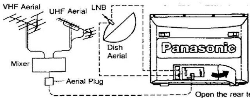
How to connect the Aerials
For connection details refer to page 17 and 18.
Connect the Plug to the Wall outlet

natural_image
Simple line drawing of a flat-screen monitor or stand (no text or symbols)Connect the AC Plug to AC Outlet.
Remove the plug from the wall outlet when the TV set is not used for a prolonged period of time.
Note :
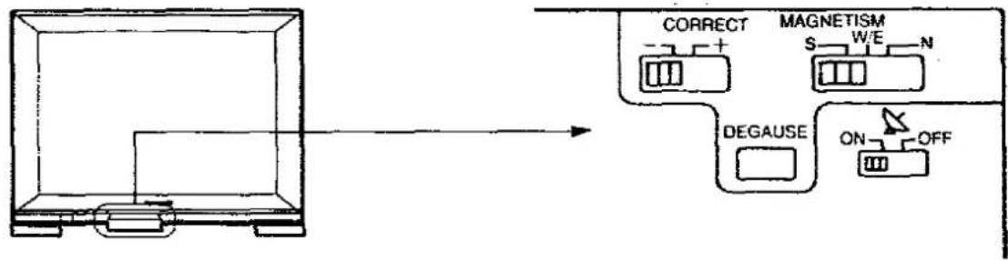
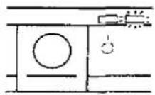
Adjust the Magnetism Correction
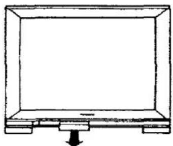
natural_image
Simple line drawing of a flat-screen monitor with a downward arrow at the base (no text or symbols)This TV has a large colour Picture tube, so depending on the TV's direction, discoloration may occur due to terrestrial magnetism.
In order to get the best picture, adjust the magnetism correction switch.
For adjustment details refer to page 21.
How to Adjust the Magnetism Correction
Batteries : Use two "R6" size alkaline batteries
1.
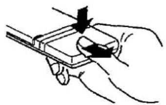
natural_image
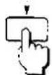
Hand holding a small electronic device with a button, no visible text or symbolsOpen the cover.
Push down stopper and remove the cover.
2.
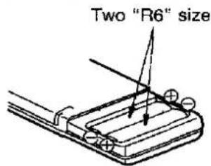
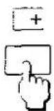
Replace the batteries.
Insert the batteries with the correct polarity as indicated by the “+” and “−” symbols.
3.

natural_image
Hand holding a small electronic device with an arrow pointing to it (no text or symbols visible)Replace the cover.
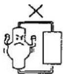
Do not use rechargeable (Ni-Cd) batteries.
They are partially different in shape and performance and may fail to ensure the desired function.
Battery precautions
The incorrect use of batteries can cause electrolyte leakage which will corrode the remote control transmitter or cause the batteries to burst. The following precautions must be observed carefully.
Old Batteries

New Batteries


Replace both batteries at the same time.
Dispose of them immediately.
Don't
Recharge

Short-circuit

Disassemble
Don't mix battery types (alkaline with carbon zinc, etc.).
Fire X

Heat of Burn
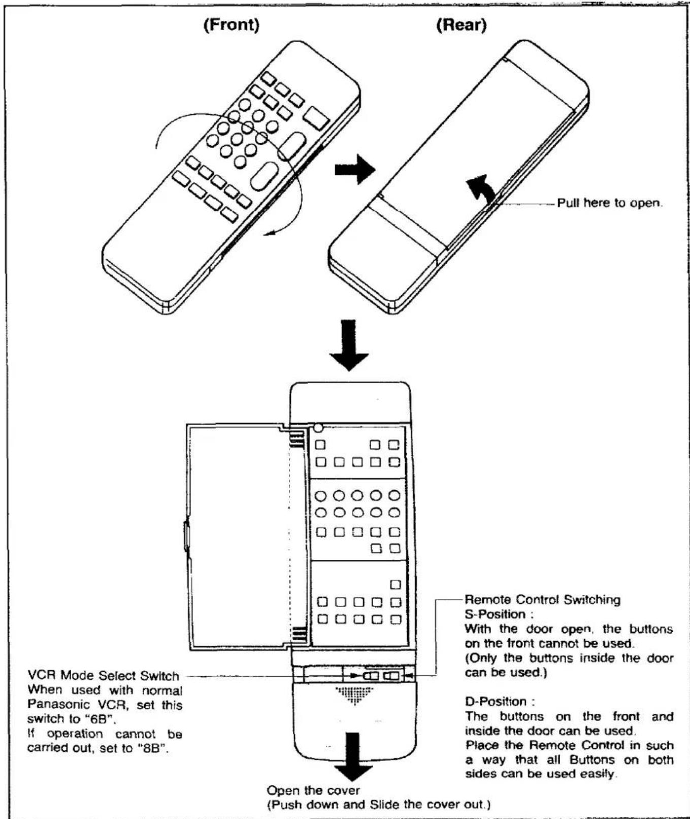
How to open the door on the rear of Remote Control
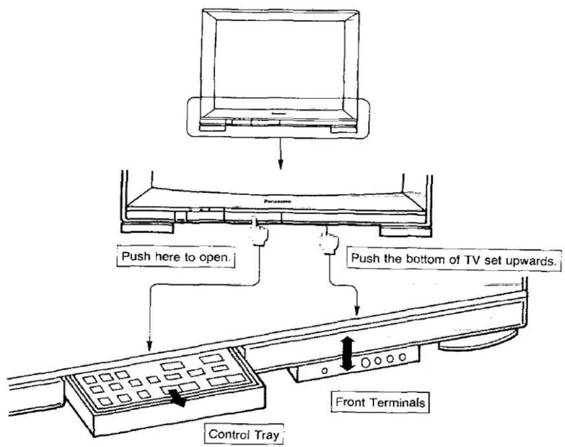
How to Open the Controls Panel
How to open the Controls tray and Front Terminals
How to Open the Rear Terminals Door

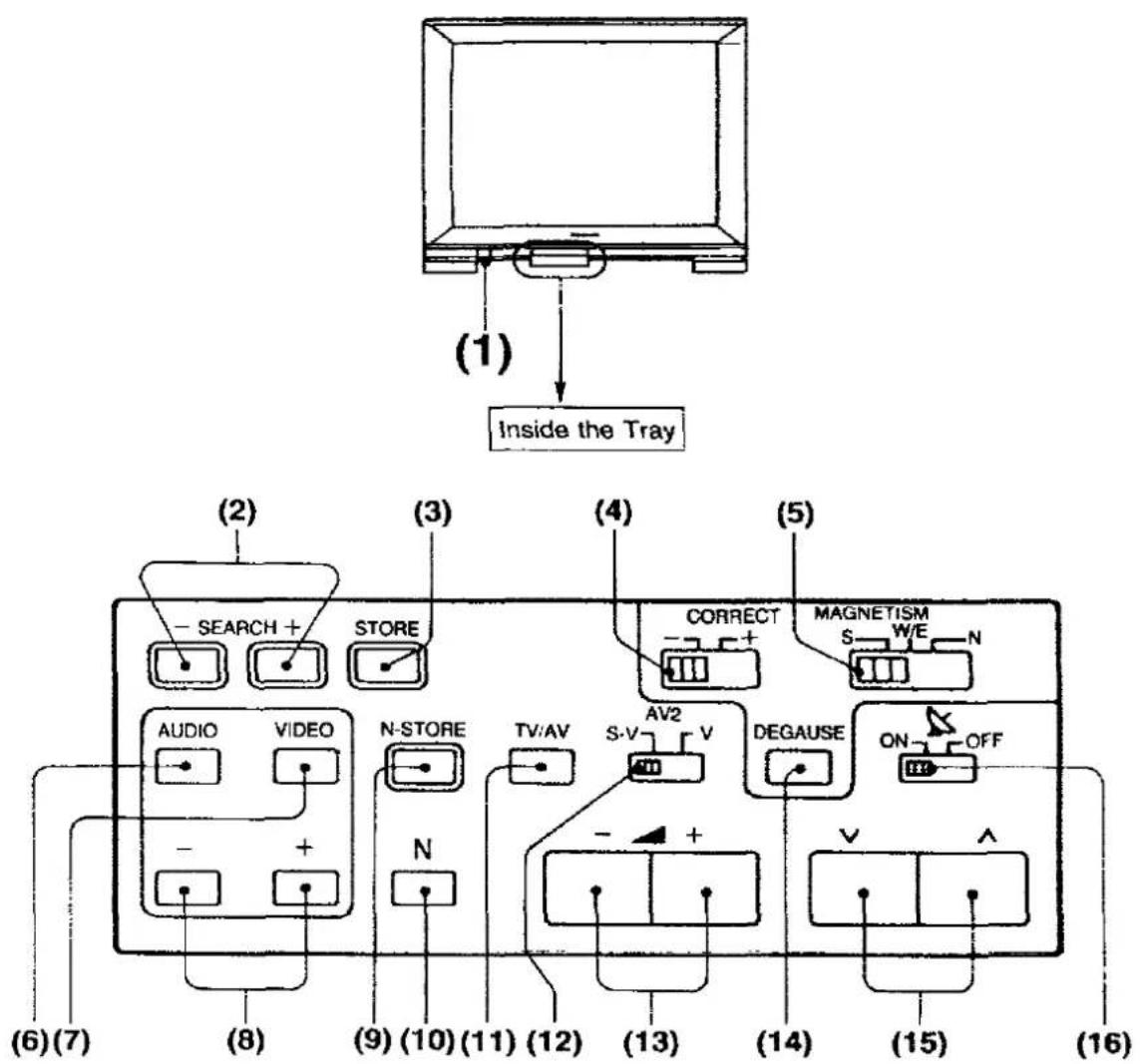
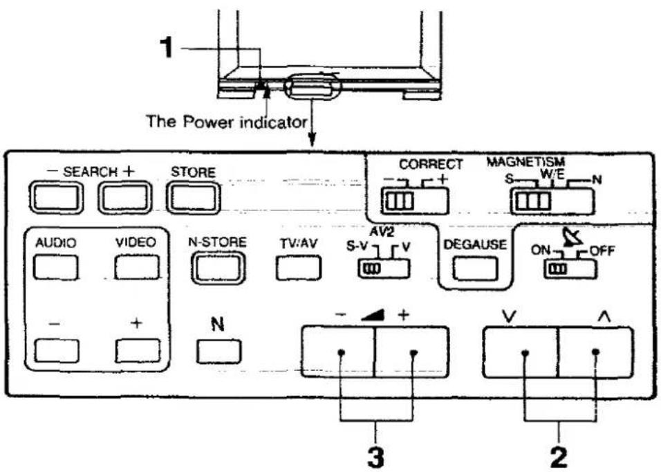
Location of Controls on the TV set
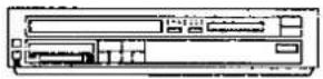
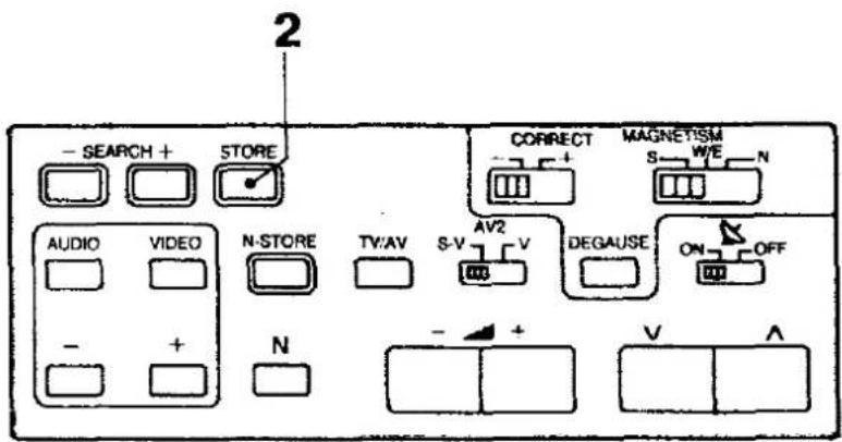
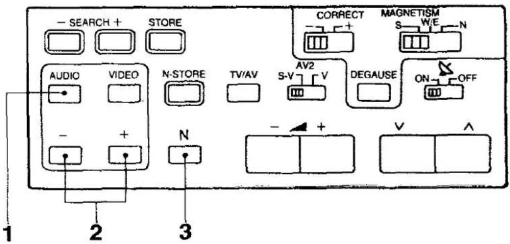
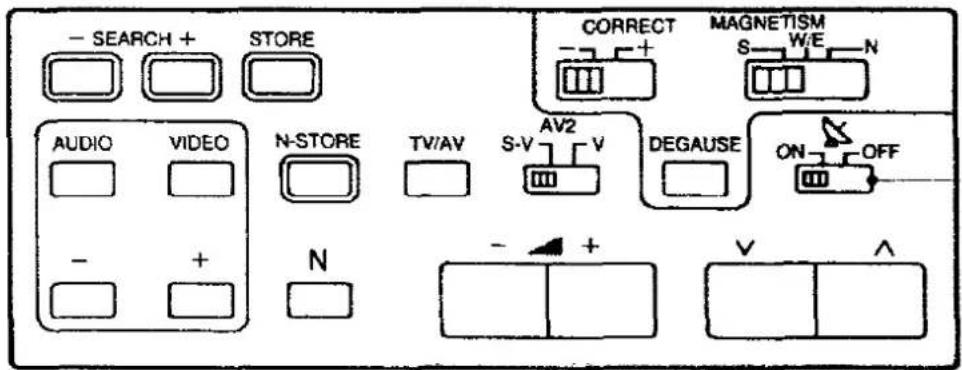
Inside the Tray
flowchart
graph TD
    A["Inside the Tray"] --> B["(1)"]
    B --> C["Search + Store"]
    C --> D["AUDIO"]
    C --> E["VIDEO"]
    D --> F["+"]
    E --> G["+"]
    H["Correct"] --> I["N-STORE"]
    I --> J["N"]
    K["MAGNETISM"] --> L["ON/OFF"]
    L --> M["S-V"]
    M --> N["S-V"]
    N --> O["AV2"]
    O --> P["V"]
    P --> Q["DEGAUSE"]
    Q --> R["+"]
    S["+"] --> T["-"]
    U["+"] --> V["(-)"]
    W["(-)"] --> X["(-)"]
    Y["(-)"] --> Z["(-)"]
    AA["(-)"] --> AB["(-)"]
    AC["(-)"] --> AD["(-)"]
    AE["(-)"] --> AF["(-)"]
    AG["(-)"] --> AH["(-)"]
    AI["(-)"] --> AJ["(-)"]
    AK["(-)"] --> AL["(-)"]
    AM["(-)"] --> AN["(-)"]
    AO["(-)"] --> AP["(-)"]
    AQ["(-)"] --> AR["(-)"]
    AS["(-)"] --> AT["(-)"]
    AU["(-)"] --> AV["(-)"]
    AW["(-)"] --> AX["(-)"]
    AY["(-)"] --> AZ["(-)"]
    BA["(-)"] --> BB["(-)"]
    BC["(-)"] --> BD["(-)"]
    BE["(-)"] --> BF["(-)"]
    BG["(-)"] --> BH["(-)"]
    BI["(-)"] --> BJ["(-)"]
    BK["(-)"] --> BL["(-)"]
    BM["(-)"] --> BN["(-)"]
    BO["(-)"] --> BP["(-)"]
    BP["(-)"] --> BQ["(-)"]
    BR["(-)"] --> BS["(-)"]
    BT["(-)"] --> BU["(-)"]
    BV["(-)"] --> BW["(-)"]
    BX["(-)"] --> BY["(-)"]
    BZ["(-)"] --> CA["(-)"]
    CB["(-)"] --> CC["(-)"]
    CD["(-)"] --> CE["(-)"]
    CF["(-)"] --> CG["(-)"]
    CH["(-)"] --> CI["(-)"]
    CJ["(-)"] --> CK["(-)"]
    CL["(-)"] --> CM["(-)"]
    CN["(-)"] --> CO["(-)"]
    CP["(-)"] --> CE
    CS["(-)"] --> CT["(-)"]
    CU["(-)"] --> CV["(-)"]
    CW["(-)"] --> CX["(-)"]
    CY["(-)"] --> CZ["(-)"]
    DA["(-)"] --> DB["(-)"]
    DC["(-)"] --> DV["(-)"]
    DW["(-)"] --> DX["(-)"]
    DX["(-)"] --> DB
    DB --> DX
    DX --> DX
    DX --> DX
    DX --> DX
    DX --> DX
    DX --> DX
    DX --> DX
    DX --> DX
    DX --> DX
    DX --> DX
    DX --> DX
    DX --> DX
    DX --> DX
    DX --> DX
    DX --> DX
    DX --> DX
    DX --> DX
    DX --> DX
    DX --> DX
    DX --> DX
    DX --> DX
    BX --> DU
    BX --> DV
    BX --> AU
    BX --> CV
    BX --> DW
    BX --> BX
    BX --> BX
    BX --> BX
    BX --> BX
    BX --> BX
    BX --> BX
    BX --> BX
    BX --> BX
    BX --> BX
    BX --> BX
No. Description
(1) Power Switch
(2) Search Up and Down Buttons
(3) Store Button
(4) Magnetism strength Switch
(5) Magnetism direction Switch
(6) Audio Menu Button
(7) Video Menu Button
(8) Menu Level Up and Down Buttons
(9) Normalisation-Store Button
(10) Normalisation Button
(11) TV / AV Selection Button
(12) AV2 Video Input Select Button
(13) Volume Up and Down Buttons
(14) Degause Button
(15) Programme Number Up and Down Buttons
(16) Satellite Mode Switch
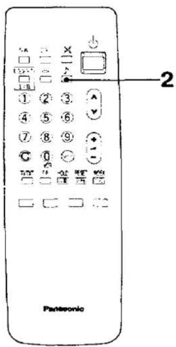
Location of Controls of the Remote Control
Front side on the Remote Control
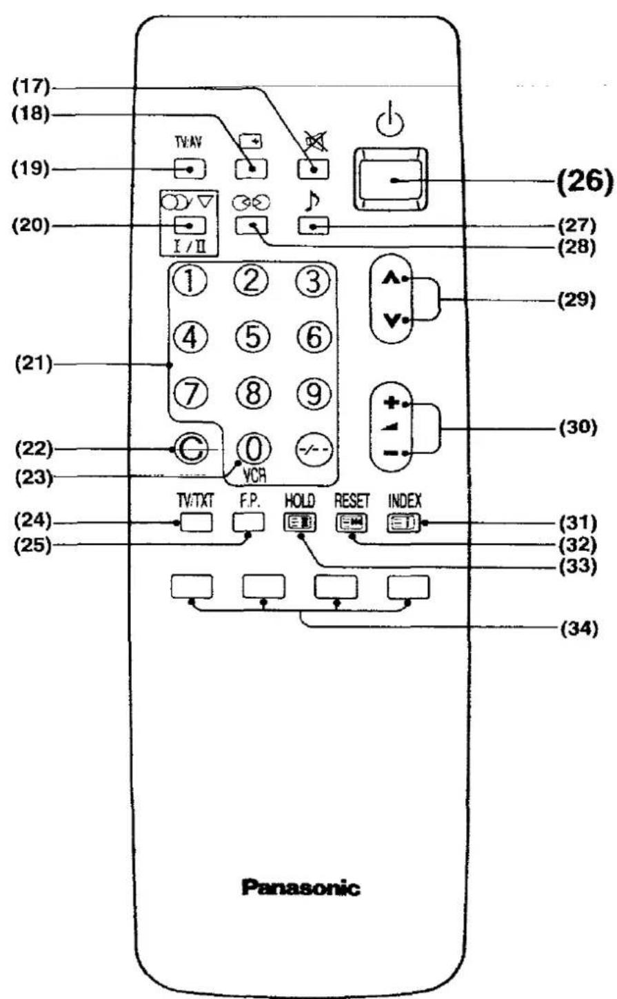
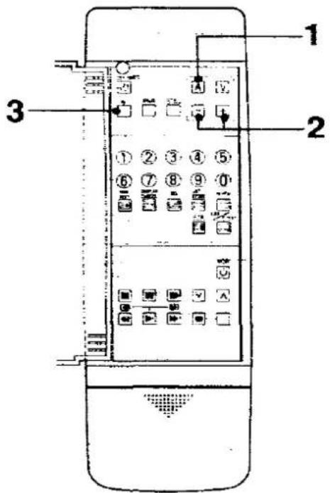
No. Description
(17) Mute Button
(18) Status Button
(19) TV / AV Selection Button
(20) Sound Selection Button
(21) Direct Programme Number Selection Buttons
(22) Direct Channel Selection Button
(23) 0/VCR Button
(24) TV / TEXT Selection Button
(25) Favorite Page Selection Button
(26) Power (Stand-by) Button
(27) Music Speech Selection Button
(28) Ambience Button
(29) Programme Number Up and Down Buttons
(30) Volume Up and Down Buttons
(31) index Button
(32) Reset Button
(33) Hold Button
(34) Colour-coded Button
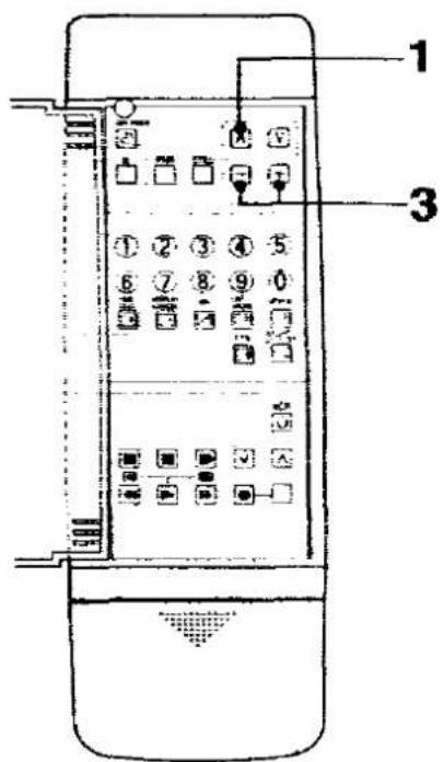
Location of Controls of the Remote Control
Behind the Door on the Remote Control

| No. | Description |
| (35) | Off-Timer Button |
| (36) | Normalisation Button |
| (37) | Picture Noise Reduction Button |
| (38) | Still Picture Button |
| (39) | Numerical Buttons |
| (40) | Time Text Button |
| (41) | Display Cancel Button |
| (42) | Mix Button |
| (43) | List Store Button |
| (44) | Pause Still Button |
| (45) | Stop Button |
| (46) | Rewind / Review Button |
| (47) | Play Button |
| (48) | Audio Menu Button |
| (49) | Video Menu Button |
| (50) | Menu Level Up and Down Buttons |
| (51) | Reveal Button |
| (52) | List / F.TEXT Button |
| (53) | Full / Top / Bottom Button |
| (54) | VCR Power Button |
| (55) | Still Advance Button |
| (56) | Programme Number Up and Down Buttons |
| (57) | Record Buttons |
| (58) | Fast Forward Button |
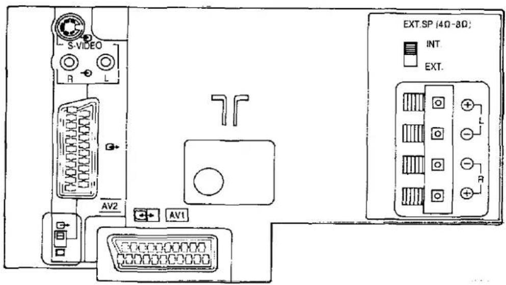
Location of Terminals
Location of Front and Rear Terminals

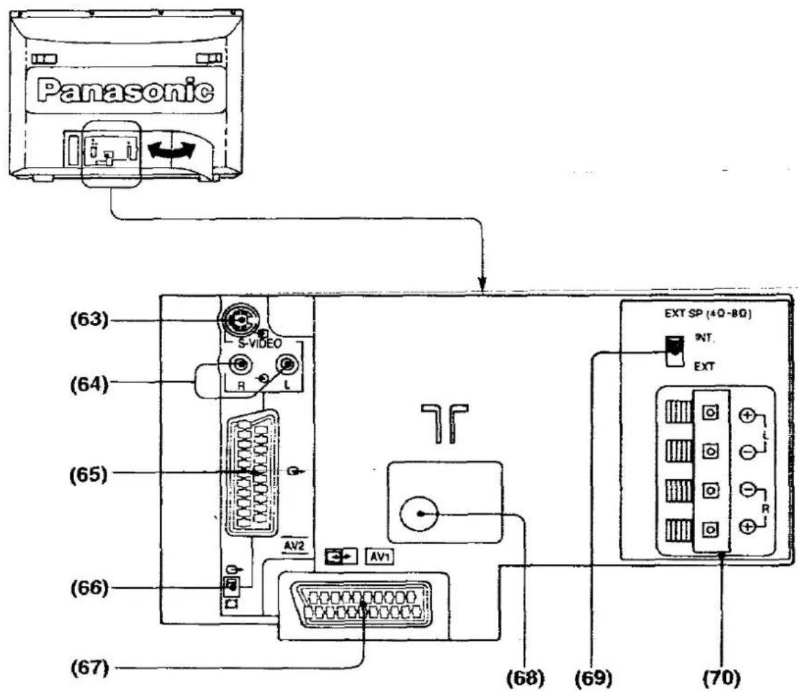
| No. | Description |
| (59) | Headphones Jack |
| (60) | AV3 S-Video Input Terminal |
| (61) | AV3 Video input Terminal |
| (62) | AV3 Audio input Terminals |
| (63) | AV2 S-Video input Terminal |
| (64) | AV2 Audio input Terminals (S-VIDEO) |
| (65) | AV2 Euro AV Terminal |
| (66) | AV2 Output Signal Selector |
| (67) | AV1 Euro AV Terminal |
| (68) | Aerial Terminal |
| (69) | Speaker Select Switch |
| (70) | External Speaker Terminals |
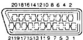
Connection of the Euro AV1 Terminals
- Audio Output (R)
- Audio Input (R)
- Audio Output (L)
- Audio GND
- Blue GND
- Audio Input (L)
- Blue Input
- No Connection
- Green GND
- No Connection
-
Green Input
-
No Connection
- Red GND
- No Connection
- Red Input
- High Speed Input
- Video GND
- High Speed GND
- Video Output
- Video Input
- GND
Connection of the Euro AV2 Terminals

- Audio Output (R)
- Audio Input (R)
- Audio Output (L)
- Audio GND
- GND
- Audio Input (L)
- No Connection
- No Connection
- GND
- No Connection
-
No Connection
-
No Connection
- GND
- No Connection
- C Input
- No Connection
- Video GND
- High Speed GND
- Video Output
- Video Input
- GND
Location of Satellite Terminals

| No. | Description |
| (71) | IF IN Terminal |
| (72) | LNB Power Switch |
| (73) | Polarizer Terminals |
| (74) | Video Output Terminal |
| (75) | Audio Output Terminals |
| (76) | Decoder Terminals |
Connection of Decoder Terminals

- Audio Output (R) 12. No Connection
- Return Audio Input (R) 13. Red Return
- Audio Output (L) 14. Blanking Return
- Audio GND 15. Red
- Blue Return 16. Blanking
- Return Audio Input (L) 17. Video Output GND
- Blue 18. Video Input GND
- AV Switch Signal 19. Baseband Output
- Green Return 20. Return Video Input
- No Connection 21. GND
11, Green
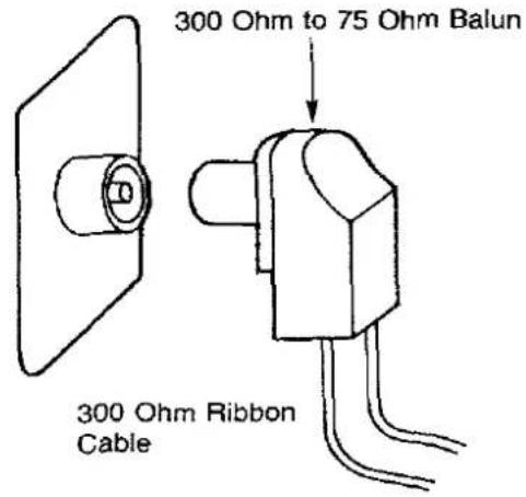
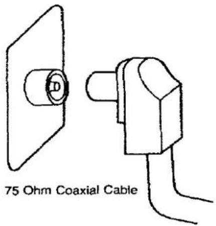
How to Connect an Aerial
To obtain the optimum picture and sound, an Aerial, the correct cable (75 Ohm coaxial) and the correct terminating plug will be required.
If a communal Aerial system is used, you may require the correct connection cable and plug between the wall Aerial socket and the TV set.
Your local Television Service Agent or Dealer may be able to assist you in obtaining the correct Aerial system for your particular area and any accessories required.
Any matters regarding Aerial installation, upgrading of existing systems or accessories required, and the costs incurred, are the responsibility of the customer.
Note :
If your existing Aerial system uses 300 Ohm ribbon cable you will require to use a 300 Ohm to 75 Ohm Balun.
See below.
Satellite Aerial Connection
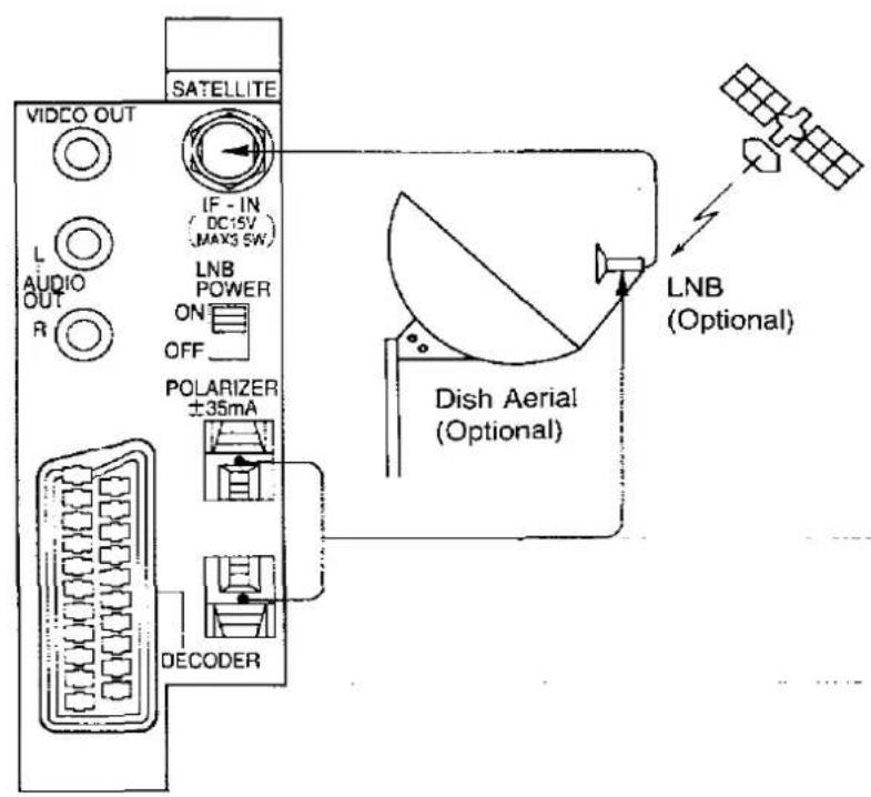
Operation
- Connect the "Dish Aerial" to the "IF-IN" Terminal.
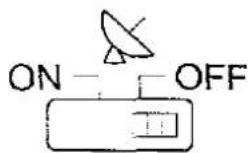
- Connect the "LNB" to the "POLARIZER" Terminals.
- Set the "LNB POWER" Switch to the "ON" Position.
Decoder Connection

Decoder Operation
TV set / decoder changeover switching is carried out automatically in accordance with the signal being received.
The decoder signal is via the "Video / Audio" terminals.
Table of Adapted Connections
| This table shows recommended connections.○ Excellent Matching in Connections○ Standard Matching in Connections△ Unrecommended Connections | ||||||
| Equipment | Description | Terminals | Page | |||
| AV1 | AV2 | AV3 | ||||
| VTR |  | Super-VHSHi-fi Stereo | ○ | ◎ | ○ | 2527 |
 | VHSHi-fi Stereo | ◎ | ○ | ○ | 23 | |
| VHS | ||||||
| Movie Camera |  | Compact VHS | △ | △ | ◎ | 2930 |
| Compact VHSHi-fi Stereo | ||||||
| Super-VHSCompact Movie | ||||||
| Super-VHSCompact MovieHi-fi Stereo | ||||||
 | VHSS-VHS | △ | △ | ◎ | 2930 | |
| TV Game | 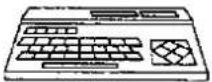 | Home Computer | △ | △ | ◎ | 2330 |
 | TV Game | △ | △ | ◎ | 2330 | |
| Monitor |  | Monitor | ○ | ◎ | △ | 28 |
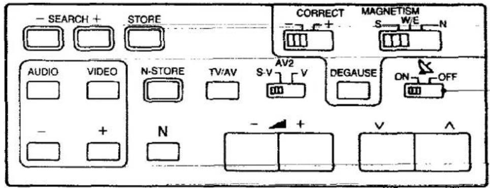
How to Adjust the Magnetism Correction
flowchart
graph TD
    A["Device"] --> B["CORRECT"]
    B --> C["MAGNETISM"]
    C --> D["S W/E N"]
    C --> E["DEGAUSE"]
    C --> F["ON OFF"]

natural_image
Simple line drawing of a 3D rectangular box with an arrow indicating direction (no text or symbols)- Confirm the Power Switch is turned off.
- Confirm the direction that the TV is facing.
- Adjust the Magnetism Correction Switches as follows.
| Direction | Direction Sw. | Strength Sw. | ||
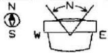 S S | North East* | N | + (-) | |
| North | + | |||
| North West* | + (-) | |||
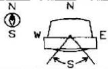 | South East* | S | + (-) | |
| South | + | |||
| South West* | + (-) | |||
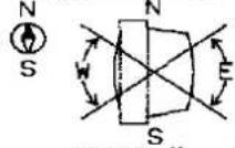 | East | W/E | + | |
| West | + | |||
- Turn on the Power Switch.
- Wait for 1 minute, and confirm the discoloration on the screen is solved.
- If the discoloration still exists on the direction with “*” mark, change the strength switch from “+” to “-”
- Press the DEGAUSE button about 10 minutes later.

Pattern 1 : Via the "AV1" Euro AV Terminal
Connect the "AV1" (Euro AV) Terminal and the other equipments as follows.
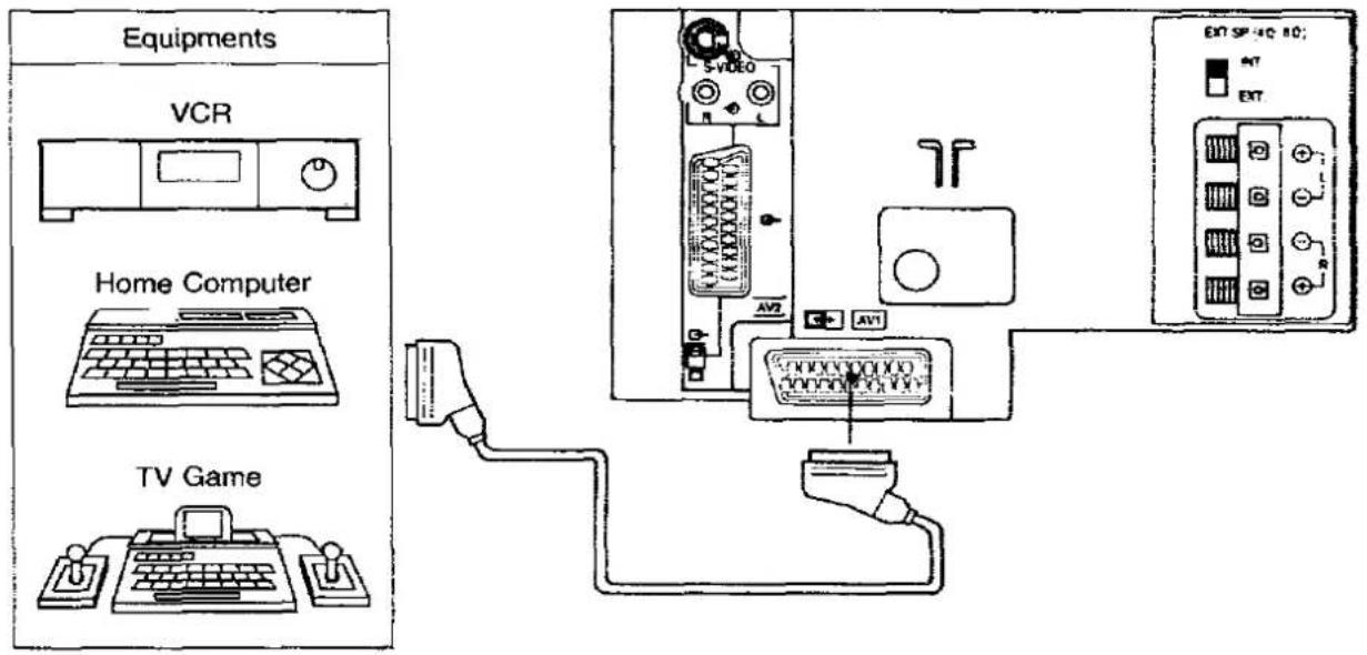
Operation
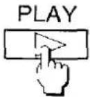
1.

Push the "PLAY" Button on the connected equipment.
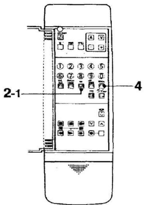
2-1.
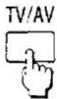
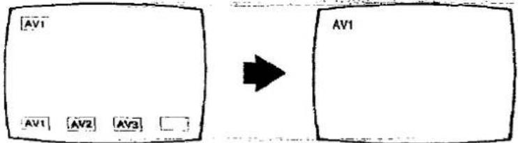
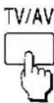
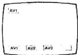
Push the "TV/AV Selection" Button on the Control Tray of TV set. On-screen display will be as shown below.
flowchart
graph LR
    A["AV1"] --> B["AV1"]
    C["AV2"] --> D["AV2"]
    E["AV3"] --> F["AV3"]
    G[" "] --> H[" "]
    style A fill:#f9f,stroke:#333
    style B fill:#ccf,stroke:#333
    style C fill:#cfc,stroke:#333
    style D fill:#fcc,stroke:#333
    style E fill:#cff,stroke:#333
    style F fill:#ffc,stroke:#333
    style G fill:#fcc,stroke:#333
    style H fill:#cfc,stroke:#333
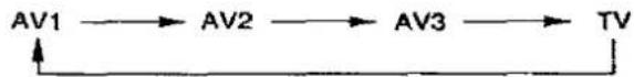
Note : By pushing sequentially the "TV/AV Selection" Button, AV mode will be changed as shown below.

flowchart
graph LR
    A["AV1"] --> B["AV2"]
    B --> C["AV3"]
    C --> D["TV"]
    D --> E
2-2.
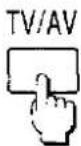
Push the "TV/AV" Button on the Remote Controller. On-screen display will be as shown below.
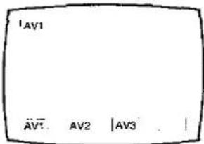


Select the "AV1" by using "Red" Button on the Remote Controller.
Pattern 2 : Via the "AV2" Euro AV Terminal
Connect the "AV2" (Euro AV) Terminal with the other equipments as follows.

Operation
1.

Push the "PLAY" Button on the connected equipment.
2-1.

Push the "TV/AV Selection" Button on the Control Tray of TV set twice. On-screen display will be as shown below.
flowchart
graph LR
    A["AV2"] --> B["AV1"]
    A --> C["AV2"]
    A --> D["AV3"]
    B --> E["AV2"]
Note : By pushing sequentially the "TV/AV Selection" Button. AV mode will be changed as shown below.
flowchart
graph LR
    A["AV1"] --> B["AV2"]
    B --> C["AV3"]
    C --> D["TV"]
    D --> A
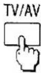
2-2.
3.

When the Normal VCR is played back, select this switch to "VIDEO" Position. (Inside the tray)
When the Super VHS VCR is played back, select this switch to "S-VIDEO" Position.

When the "S-VIDEO" Position is selected, "S-VIDEO" symbol will be appeared on the screen as shown above.
Note :
Do not connect the S-Video Cable together with Euro AV Cable when the Super VHS Cassette tape is played back via Euro AV Cable.
Pattern 3 : Via the "AV2" S-Video and Audio Terminals
Connect the "AV2" (S-Video and Audio R and L) Terminals and the other equipments as follows.

Operation
1.

Select the "AV2 Video Input Select" Switch to the "S-VIDEO" Position. (Inside the Tray)
2.

Push the "PLAY" Button on the connected equipment.
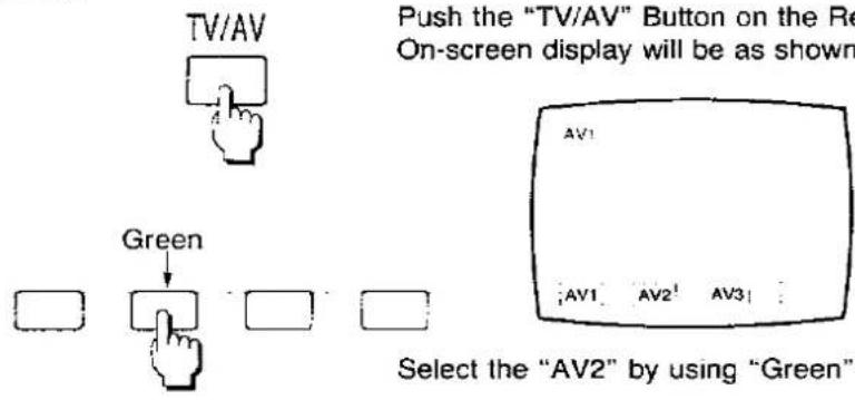
3.
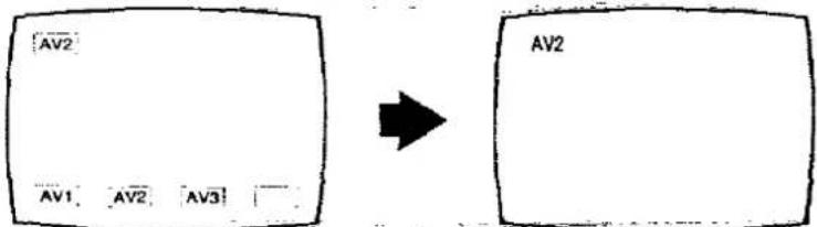
Push the "TV/AV" Button on the Remote Controller. On-screen display will be as shown below.

4.


Select the "AV2" by using "Green" Button on the Remote Controller.
Helpful Hint : Tuner / Monitor Out Switch

This switch is used for AV2 terminal output signal selection.

Tuner Out
At the tuner out position, tuner output signal is outputted from the "AV2" Terminals.
(During AV mode, the tuner signal which is selected before changing to AV mode is outputted.)

Monitor Out
At the monitor out position, displayed signal on the screen is outputted from the "AV2" Terminals.
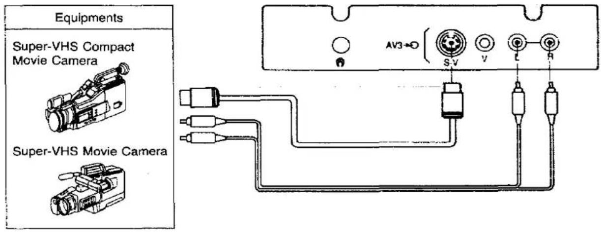
Pattern 4 : Via the "AV3" S-Video and Audio Terminals
Connect the "AV3" (S-Video / Video and Audio) Terminals and the other equipments as follows.
Operation
1.

Push the "PLAY" Button on the connected equipment.
2-1.
Push the "TV/AV Selection" Button on the Control Tray of TV set.
Note :
Pushing sequentially the "TV/AV Selection" Button, AV mode will be changed as shown below.

flowchart
graph LR
    A["AV1"] --> B["AV2"]
    B --> C["AV3"]
    C --> D["TV"]
    D --> A
2-2.
Push the "TV/AV" Button on the Remote Controller. On-screen display will be as shown below.


Select the "AV3" by using "Yellow" Button on the Remote Controller.
Pattern 5 : Via the "AV3" Video and Audio Terminals
Connect the "AV3" (Video / Video and Audio) Terminals and the other equipments as follows.

| Operation | ||
1.  | Push the "PLAY" Button on the connected equipment. | |
2-1.  | Push the "TV/AV Selection" Button on the Control Tray of the TV set. Note: By pushing sequentially the "TV/AV Selection" Button, AV mode will be changed as shown below. AV1 → AV2 → AV3 → TV | |
2-2. 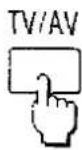   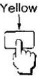 | Push the "TV/AV" Button on the Remote Controller. On-screen display will be as shown below. 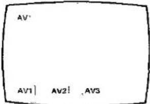 Select the "AV3" by pushing "Yellow" Button on the Remote Controller. Select the "AV3" by pushing "Yellow" Button on the Remote Controller. | |
Connecting the external Speakers
1. Connect the external Speakers as follows.
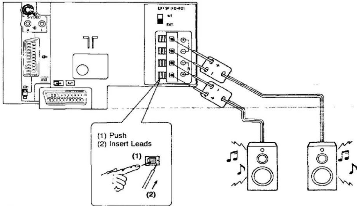
2.
EXT.SP (4Ω-8Ω)
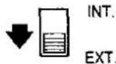
Set the "EXT." Position.
"INT." Position : Internal speakers are selected.
"EXT." Position : External speakers are selected.
Note :
(1) If speakers cause disturbance in picture magnetism, place the speakers as far as possible from the TV set.
(2) If speaker terminals are shorted, sound will be cut off.
Turn the TV set off then turn on again to reset the protection circuit.
(3) External speakers impedance 4 - 8 Ω.
Connecting the Headphones
Connect the Headphones as follows.

When the Headphones plug is inserted into the Headphones jack, no sound is heard from the speakers, and you can listen with the Headphones only.
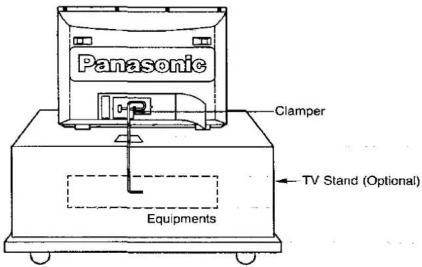
Helpful Hint
Connection Cables arrangement
When you connect the Euro or Decoder Terminal, install the cable as shown below. (e.g. Connecting "AV2")
Method 1 (If channel numbers are not known)


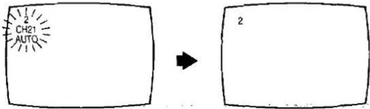
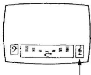
Push the Search Up "+" or Down "-" Button, and the TV station broadcasting on the next higher or lower channel will be tuned. The on-screen display will appear as shown below.
1) Channel indicator
2) Programme Position indicator
3) On-screen information
Programme Up-Down operation activates indicators

flowchart
graph TD
    A["1) CH21"] --> B["2)"]
    B --> C["3)"]
    D["PRG ∨ ∧"] --> A
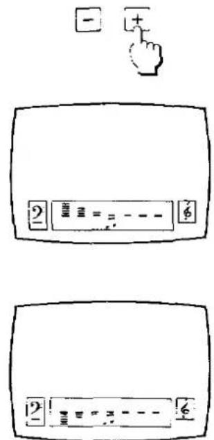
The TV will automatically stop searching when a channel has been found.
If this is not a desired channel, push either Search Up "+" or Down "-" Button to start searching again.
The channel indicator will be changed as shown below.
Search Up operation :
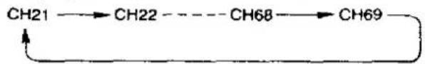
flowchart
graph LR
    A["CH21"] --> B["CH22"]
    B -.-> C["CH68"]
    C --> D["CH69"]
    D --> E
Search Down operation :
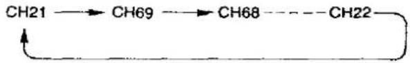
flowchart
graph LR
    A["CH21"] --> B["CH69"]
    B --> C["CH68"]
    C --> D["CH22"]
    D --> E
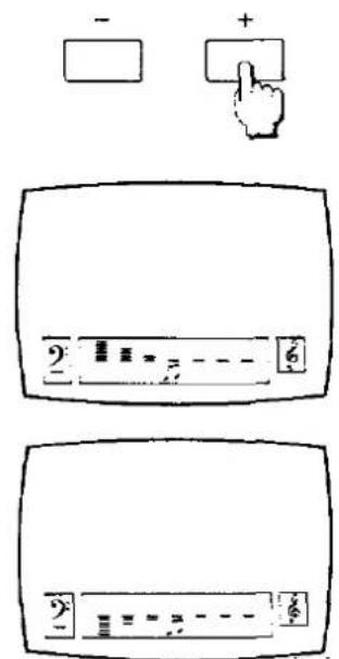
2.
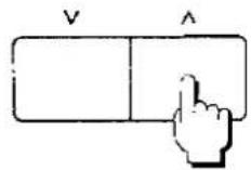
Select a desired programme number (1 through 50) by using programme Up "^" or Down "√" Button.
The Programme Number indicator on screen will be changed.
3.

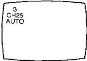
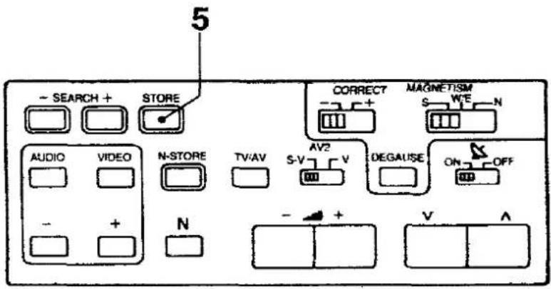
When the desired channel is found and the desired programme number is selected, push the "STORE" Button.
The on-screen display will flash and be memorized.
The on-screen display will be changed as shown below.
4.
Repeat Steps 1 through 3.
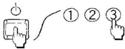
Method 2 (If channel numbers of TV stations are known)
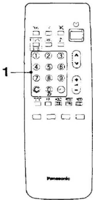
1-1.
Select your desired programme number by using the remote control keys.

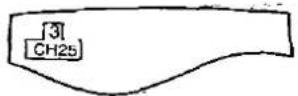
When selecting one-digit programme Nos 1 to 9. e.g. To select Programme No. "3". Push the "3" Button.


When selecting two-digit programme Nos. 10 to 50. e.g. To select Programme No. "25". Push the two-digit "--" Button.
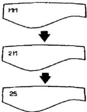
flowchart
graph TD
    A["n1"] --> B["2n1"]
    B --> C["25"]

Push the "2" Button.

Push the "5" Button.
1-2.
Select the actual channel number which can be received in your area directly with the remote control.

e.g. To select actual channel No. "25".
Push the "C" Button.

Push the "2" Button.


Push the "5" Button.
2.

Push the "STORE" Button in the control tray.
3.
Repeat steps 1 through 2 with the remaining channels. A maximum of 50 channels can be programmed.
Tuning of the Satellite Broadcasting

1.
Select your desired programme number.
(For Programme number selection, refer to page 40.)
Note :
If you select the programme number which channel number already stored, the former channel number will be canceled and the satellite channel will replace.
2.

Push the "C" Button.
The on-screen display appears as shown below.


You can select the desired satellite mode by pushing "Colour-Coded" Buttons.
3.
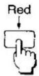


e.g. To select the satellite "AS-1A"
Push the red button. The on-screen display appears as shown below.
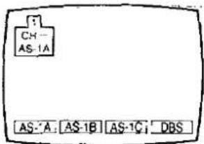
4.
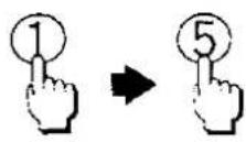
Select your desired channel number, by using "Direct Programme Number Selection" Buttons.
e.g. Selecting Channel 15.
Push the "1" Button first, then push the "5" Button.
When you select one digit Programme Number (1 to 9), push the "0" Button first, then push your desired Programme number's Button.
e.g. Selecting Channel 3.
Push the "0" and "3" Button.

Note :
You can select Channels as shown below.
| Satellite | Channel |
| AS-1A | 1 - 16 |
| AS-1B | 1 - 16 |
| AS-1C | 1 - 16 |
| DBS | 1 - 40 |
For the channel allocation, refer to page 91 and 92.
5.

Push the "STORE" Button on the control tray.
6.
Repeat steps 2 through 5 with the remaining channels.
Helpful Hint
7.
By pushing the "Status" Button, you can call a list which contains the programme numbers and actual channel numbers already stored.
For "Status" Button detail, refer to page 58.
Basic Operation on the TV set
1.

Power on/off operation
Push the "Power" Button to turn the TV set on.
The Power indicator lights up.
However on-screen display does not appear, then push the "Power (Stand-by)" Button on the remote controller.
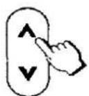
2.
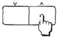
Programme Number Up / Down Operation
Push the Programme Number Up “^” Button to select the higher programme numbers.

Push the Programme Number Down "V" Button to select the lower programme numbers.
3.

Volume Up / Down Operation
Push the Volume Up "+" Button to increase the sound level.
The on-screen indicator will move from Left to Right.

Push the Volume Down "—" Button to decrease the sound level.
The on-screen indicator will move from Right to Left.
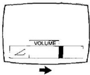

General Operation on the TV set
To adjust the Video menu
Picture has been set according to a factory-preset standard. You can change these settings according to your desired level.
1.

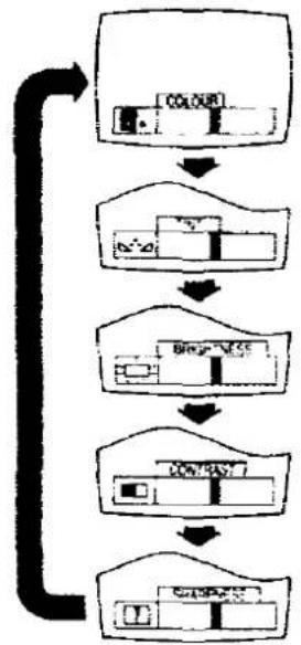
To select the Video menu, use the "Video Menu" Button.
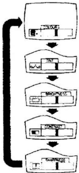
By pushing this button sequentially, the on-screen display will be changed as follows.

flowchart
graph LR
    A["COLOUR"] --> B["NTSC TINT"]
    B --> C["BRIGHTNESS"]
    C --> D["CONTRAST"]
    D --> E["SHARPNESS"]
    E --> A
Note :
"NTSC TINT" indicator.
When the NTSC playback signal is received, "NTSC TINT" indicator will be displayed on the screen.
flowchart
graph TD
    A["Input Image"] --> B["Process Step 1"]
    B --> C["Process Step 2"]
    C --> D["Process Step 3"]
    D --> E["Output Image"]
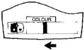
2.
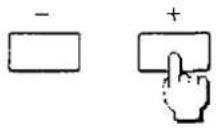

Select the desired level by using "Menu Level Up and Down" Buttons.
(e.g. Menu to be selected is "Colour" menu.)
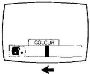
Push the "+" Button to increase the level of selected function and the level indicator will move from Left to Right.
Push the “—” Button to decrease the level of selected function and the level indicator will move from Right to Left.
3.
Repeat steps 1 through 2.
4.

After presetting the each "Video Menu", push the "Normalisation-Store" Button.
By pushing the "Normalisation-Store" Button on the TV set, you can get the following controls memorised at desired levels:
Volume, Colour, NTSC TINT, Brightness, Contrast, Sharpness. The Fine Tuning Function is not stored.
Helpful Hint
5.
By pushing this button, the levels of Volume, Colour, NTSC TINT, Brightness, Contrast, Sharpness and Balance will be restored to the levels memorised in "Normalisation-Store" Function.
To adjust the Audio menu
Audio has been set according to a factory-preset standard. You can change these settings according to your desired level.
1.

To select the Audio menu, use the "Audio Menu" Button. By pushing this button sequentially, the on-screen display will be changed as follows.
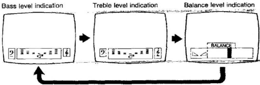
flowchart
graph LR
    A["Bass level indication"] --> B["Treble level indication"]
    B --> C["Balance level indication"]
    C --> D["Balance icon"]
To adjust the Balance
1.

Select the "Balance" menu by using "Audio Menu" Button.
2.

Select the desired level by using "Menu level Up and Down" Buttons.

Push the "+" Button to bias sound to the right hand side.
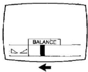
Push the “—” Button to bias sound to the left hand side.
Helpful Hint
3.

By pushing this button, the level of Volume, Colour, NTSC TINT, Brightness, Contrast, Sharpness and Balance will be restored to the levels memorised in "Normalisation-Store" Function.
Note :
For "Normalisation-Store" Function details, refer to page 42.
To adjust the Bass and Treble

1.
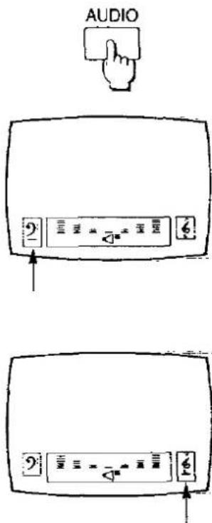
Select the "Bass" or "Treble" menu by using "Audio Menu" Button.
Bass level indicator
Treble level indicator

Select the "Music" or "Speech" mode by using "Music / Speech Selection" Button.
The on-screen display will be changed as shown below.
(e.g. Condition to be selected is Bass menu.)
Music mode
Speech mode
Select the desired level by using "Menu level Up and Down" Buttons.
(e.g. Condition to be selected is Bass menu in Music mode.)
Push the "+" Button to increase the level of selected function.
Push the “—” Button to decrease the level of selected function.
4.
Repeat steps 1 through 3.
Basic Operation on the Remote Controller
Setting TV stations

The Remote Control can only be used when the "Power" Switch on the TV set is in the on state.
Push this button on the Remote Controller to turn the TV set on. or push any Digit button (0 - 9) to turn the TV set on. (The stand-by indicator will go off.) Push it again to turn the TV set off.
Note :
Do not leave the TV set in the stand-by condition for a long period of time. It is better to switch it off when you are away for a extended period of time.
Push the Programme Number Up " " Button to select the higher programme numbers.

Push the Programme Number Down " " Button to select the lower programme numbers.
3.

Push the Volume Up "+" Button to increase the sound level.
Push the Volume Down "—" Button to decrease the sound level.
4.

To select the one digit Programme number (0 - 9), push the "Direct Programme Number Selection Buttons".
e.g. To select number "3" Push the "3" Button.

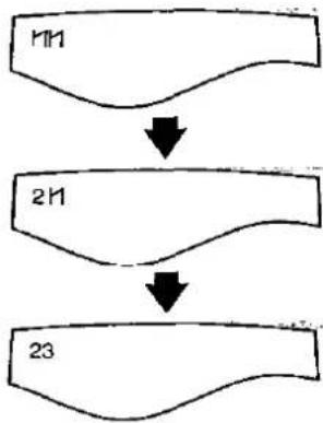
To select the two digit Programme number (10 - 50).
e.g. To select number "23"

Push the “-/--” Button.
The screen will display as shown in the pictures.
Push the "2" Button.

Push the "3" Button.
flowchart
graph TD
    A["M"] --> B["N"]
    B --> C["23"]
5.

The Channel number can be entered directly.
Push the "C" Button.
The screen will display as shown in the pictures.

Enter a desired channel number by pushing the "Direct Programme Number Selection" Buttons.
e.g. To tune to 36

Push the "3" Button.
Push the "6" Button.
The programme number will be remained.

flowchart
graph TD
    A["CH-"] --> B["AS-1A AS-1B AS-C OBS"]
    B --> C["CH3-"]
    C --> D["CH36"]
    D --> E["1"]
General Operation on the Remote Controller
Operating Video Menu

Picture has been set according to a factory-preset standard.
You can change these settings according to your desired level with the remote controller.
1.

To select the Video menu, use the "Video Menu" Button.
By pushing this button sequentially, the on-screen display will be changed as follows.

flowchart
graph LR
    A["COLOUR"] --> B["NTSC TINT"]
    B --> C["BRIGHTNESS"]
    C --> D["CONTRAST"]
    D --> E["SHARPNESS"]
    E --> A
Note :
"NTSC TINT" indicator
When the NTSC playback signal is received, "NTSC TINT" indicator will be displayed on the screen.
flowchart
graph TD
    A["Input Image"] --> B["Processing Unit"]
    B --> C["Output Label"]
    C --> D["Final Output"]
    style A fill:#f9f,stroke:#333
    style B fill:#ccf,stroke:#333
    style C fill:#cfc,stroke:#333
    style D fill:#fcc,stroke:#333
2.


Select the desired level by using "Menu level Up and Down" Buttons.
(e.g. Menu to be selected is "Colour")
Push the "+" Button to increase the level of selected function and the level indicator will move from Left to Right.
Push the “—” Button to decrease the level of selected function and the level indicator will move from Right to Left.
3.
Repeat steps 1 through 2.
Helpful Hint :
4.

By pushing this button, the levels of Volume, Colour, NTSC TINT, Brightness, Contrast, Sharpness, and Balance will be restored to the levels memorised in "Normalisation-Store" Function.
Note :
For "Normalisation-Store" Function details, refer to page 42.
Operating Audio Menu
Audio has been set according to a factory-preset standard.
You can change these settings according to your desired level with the remote controller.
1.

To select the Audio menu, use the "Audio Menu" Button.
By pushing this button sequentially, the on-screen display will be changed as follows.

flowchart
graph LR
    A["Bass level indication"] --> B["Treble level indication"]
    B --> C["Balance level indication"]
    C --> D["BALANCE"]
To Adjust the Balance
1.

Select the "Balance" menu by using "Audio Menu" Button.
2.
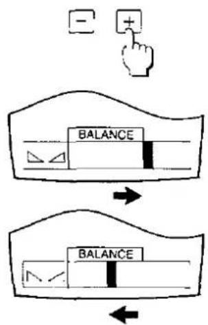
flowchart
graph TD
    A["Hand Button"] --> B["Balance"]
    B --> C["Arrow to Top Left"]
    B --> D["Arrow to Bottom Right"]
Select the desired Audio R/L balance by using "Menu Level Up and Down" Buttons.
Push the “+” Button to bias sound to the right hand side.
Push the “—” Button to bias sound to the left hand side.
Helpful Hint
3.

By pushing this button, the level of Volume, Colour, NTSC TINT, Brightness, Contrast, Sharpness and Balance will be restored to the levels memorised in "Normalisation-Store" Function.
Note :
For "Normalisation-Store" Function details, refer to page 42.
To adjust the Bass and Treble

Select the "Bass" or "Treble" menu by using "Audio Menu" Button.

Bass level indicator
Treble level indicator
2.

Select the "Music" or "Speech" mode by using "Music/ Speech Selection" Button on the other side of remote controller.
If it doesn't work, refer to description of Remote Control Switching on page 5.
The on-screen display will be changed as shown below.
(e.g. Condition to be selected is Bass menu.)
Music mode
Speech mode
3.
Select the desired level by using "Menu level Up and Down" Buttons.
(e.g. Condition to be selected is Bass menu in Music mode.)
Push the "+" Button to increase the level of selected function.
Push the “—” Button to decrease the level of selected function.
4.
Repeat steps 1 through 3.
NICAM Digital Stereo Reception
When a stereo, dual-soundtrack or normal NICAM programme is being received, the indicators light to inform you of the type of broadcast.
1.
Sound output can be selected by pushing this button.
○: Stereo is received
: Mono is received
I : Dual I is received
II : Dual II is received
Note :
If the stereo signal is weak or the receiving condition extremely poor, it is recommendable to switch to the "Mono" Mode.
| Type of broadcast | On-screen indication | Remark |
| Regular broadcast(Standard Audio) |  | Normal use |
| Regular +NICAM Mono I(Dual I) |  | You can select either of the “Dual I / Mono” Condition. |
| Regular +NICAM Stereo |  | You can select either of the “Stereo / Mono” Condition. |
| Regular +NICAM Dual Mono(Dual I / II) |  | You can select either of the “Dual I / Dual II / Mono” Condition. |
| Note :Even when the contents of the receiving signal undergo changes, selection mode is kept intact. | ||
Useful functions
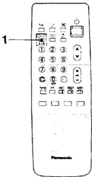
1-1.

Push this button.
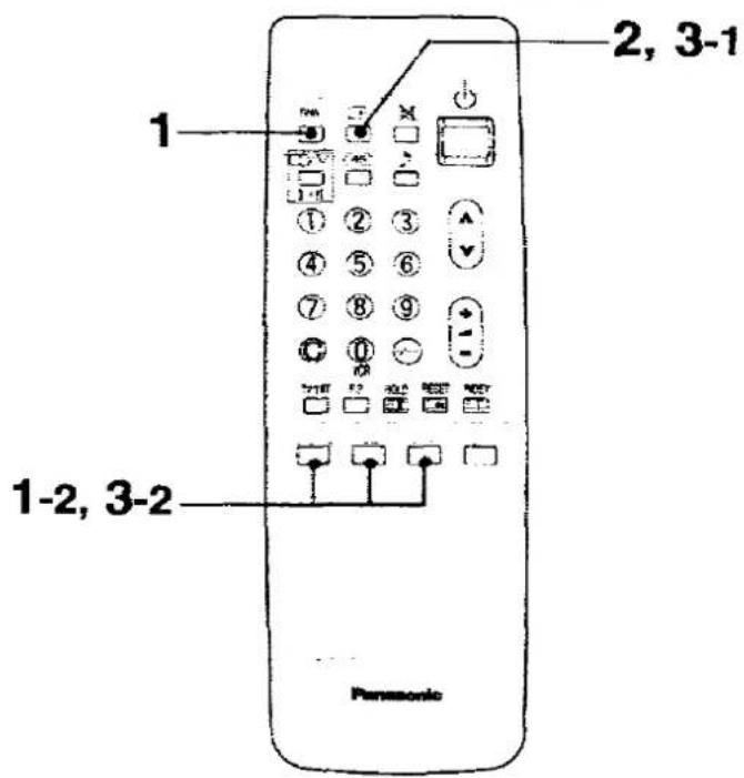
You can select the three AV modes.
The on-screen display will appear as shown below.
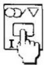
1-2.
Select your desired AV mode by using these buttons.
The Background colour of AV modes List agrees with these 3 colour buttons.
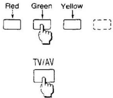
Operation:
AV1: Push "Red" Button
AV2 : Push "Green" Button.
AV3 : Push "Yellow" Button.
Push this button again to return to the TV mode.
Then your selected AV mode will be memorised.
For operation details, refer to page 23 to 30.
2.

Push this button to activate on-screen display as shown below.
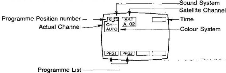
flowchart
graph TD
    A["Programme Position number"] --> B["Actual Channel"]
    B --> C["SAT A 02"]
    C --> D["Sound System"]
    C --> E["Satellite Channel"]
    C --> F["Colour System"]
    C --> G["PRG1 PRG2"]
    G --> H["Programme List"]
Helpful Hint:
To display the programme list
You can call a list which contains the programme numbers and actual channel numbers already stored.
3-1.

Push the "STATUS" Button.
3-2.
Red
Green


Select your desired programme list by using red or green button.
If you select the "PRG1", the screen will display programme numbers VCR to 26.
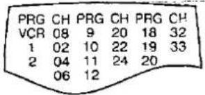
If you select the "PRG2", the screen will display programme numbers 27 to 50.


Push the "STATUS" Button again, the on-screen display will be canceled.

4.

Push this button to obtain better acoustic sound from the speakers.
Ambience sound is a dynamic sound system that gives a feeling of greater acoustic presence.
The system automatically selects stereo ambience or monaural ambience according to the broadcast signal.
TV mode: Depend on broadcast signal
AV mode: Stereo ambience
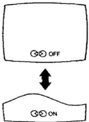
flowchart
graph TD
    A["OFF"] --> B["ON"]
    style A fill:#fff,stroke:#000
    style B fill:#fff,stroke:#000
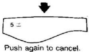
5.
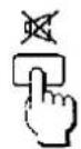
Push this button once to mute the sound.
The on-screen display will appear as shown in the pictures.
Top previous sound level will appear in red for a few seconds.
The "Mute" symbol will remain.
Push the button once again or push the Volume "Up" or "Down" Button to restore the previous sound level.
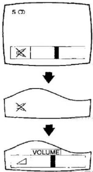
flowchart
graph TD
    A["5 Ω"] --> B["↓"]
    B --> C["×"]
    C --> D["VOLUME"]
6.

After the "Music / Speech" Menu have been memorised, you can select either of them.
Note :
To memory "Music / Speech" Menu, refer to page 45 to 46 or 53 to 54.

flowchart
graph TD
    A["Music mode"] <--> B["Speech mode"]
    style A fill:#f9f,stroke:#333
    style B fill:#bbf,stroke:#333


flowchart
graph TD
    A["OFF TIMER"] --> B["30"]
    B --> C["60"]
    C --> D["90"]
    D --> E["0"]
You can set the unit to turn off automatically after a certain time between 30 minutes and 90 minutes while viewing a TV programme.
Each time you push the "OFF TIMER" Button, the display changes as follows.
Note :
Remaining time is displayed continuously on the screen.
To Cancel the Off-Timer
Set the Off-Timer condition to "0" by pushing "OFF TIMER" Button.
8.


The Picture Noise Reduction system is a system designed to effectively reduce the Picture Noise.
The on-screen display will appear as follows.
The Picture Noise Reduction is in ON condition.

The Picture Noise Reduction is in OFF condition.
9.

This function can be used to freeze the action on the screen and display a still picture.
Push "STILL" Button to freeze the moving picture into a still picture.
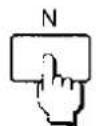
To Cancel the Still picture
- Push the "STILL" Button again.
- Push the "N" Button.
Connection
- Connect the external aerial to the RF Input Socket on the VCR.
- Connect the aerial terminal on the TV set to the RF Output Socket on the VCR with the supplied DIN-DIN Coaxial Cable.

The adjustments described on this page are not necessary, if the VCR is connected to the TV set via the Video/Audio output Sockets.
Method
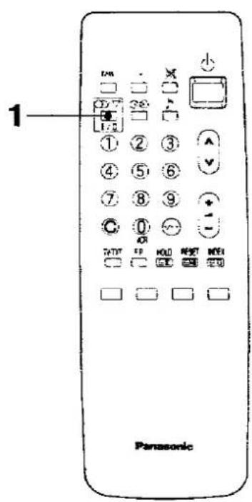
1.

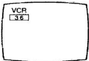
Select the "VCR" position by using "0/VCR" Button on the Remote Controller.
2.

Select the channel 36 directly with the remote control.
Push the "C" Button.

Push the "3" Button.

Push the "6" Button.
| 3. Push the VCR On/Off Button on the VCR to turn the VCR On. | |
4.  | Push the "PLAY" Button on the VCR.Push the "PLAY" Button on the VCR. |
5. 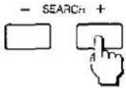 | Push the Search Up "+" or Down "-" Button in the control tray on the TV set until the Play Back picture appear clearly.Note :If the test signal from the VCR is received the Picture may not be stable. |
6.  | Push the "STORE" Button in the control tray. |
| 7. | The TV is now ready to receive the RF output signal from the VCR. |
General Operation of the Satellite Broadcasting

1.

(The satellite broadcasting channel must be selected.) Select your desired "Audio Mode" by using the "Sound Selection" Button.
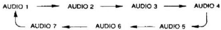
flowchart
graph LR
    A["AUDIO 1"] --> B["AUDIO 2"]
    B --> C["AUDIO 3"]
    C --> D["AUDIO 4"]
    D --> E["AUDIO 5"]
    E --> F["AUDIO 6"]
    F --> G["AUDIO 7"]
    G --> A
| Audio Mode | Sound Out | Sub Carrier (MHz) |
| Audio 1 | Stereo | 7.027.20 |
| Audio 2 | Stereo | 7.387.56 |
| Audio 3 | Mono | 7.02 |
| Audio 4 | Mono | 7.20 |
| Audio 5 | Mono | 7.38 |
| Audio 6 | Mono | 7.56 |
| Audio 7 | Mono | Variable(6 MHz - 9 MHz) |
2-1.

When the "Audio 7" position is selected, you can select the "Sound Frequency" level.
Push the "Audio Menu" Button until the "SIF" indicator displayed on the screen.
The "Sound Frequency" level can be selected in steps between 6 MHz to 9 MHz.

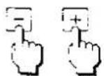
2-2.

To select the higher sound frequency level, push the "+" Button.
To select the lower sound frequency level, push the “—” Button.

Note :
When the sound frequency level will be adjusted, the "SIF" indicator's colour will be changed: Cyan to Yellow.
Helpful Hint
3-1.

Under normal reception condition this function is not used. However, if your receiving signal is poor reception or constant interference, a slight adjustment of the polarizer control may improve the picture and sound quality.
Push the "Video Menu" Button until the "CN Level" indicator displayed as follows.
Programme Number
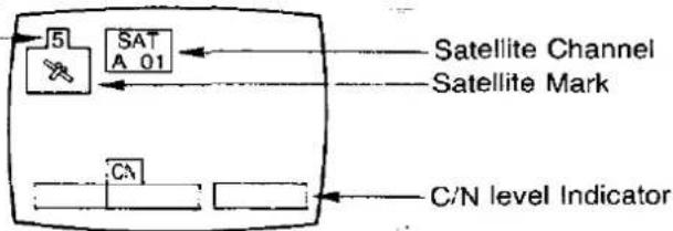
3-2.
Push the "+" or "-" Button to adjust the receiving satellite signal level.
Satellite Mark :
| Flashing | Adjustable C/N Level |
| Not flashing | C/N Level (Not Adjustable) |
3-3.

To return to the normal picture, push the "Normalisation" Button.
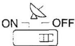
Satellite Mode Switch Operation
1
1.
OFF Position
Normally, leave it at "OFF" position. At this position, normal TV and satellite broadcasts can be viewed.
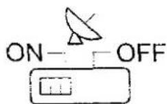
ON Position
Use this position during unsupervised recording. This function is operative only when the TV is at stand-by mode.

When activated, a green indicator on the TV set lights up.
| Recording One / Viewing Another mode |
| Satellite broadcasts can be recorded while programmes on normal TV broadcasts are being viewed. |
| 1.Select the desired satellite broadcasting channel. |
| 2.Set the VCR at recording mode.For further details on VCR operations, refer to its instructions manual. |
| Note :While watching normal TV broadcast, you can select the viewing channel as you desire. However, when selecting the satellite broadcasting channel by means of the Last channel Memory function, the channel to be recorded on the Recording One / Viewing Another mode will be changed. |
Unsupervised Recording mode
4,6
When recording while the TV is being turned off.
1.
Select the desired satellite broadcasting channel.
2.
Select the desired audio mode. (For further details, refer to page 65.)
3.

By using the Power (Stand-by) button on the remote controller to set the TV at stand-by mode.
TV set
4.

Set the Satellite Mode switch at "ON" position.
A green indicator lights up.
5.
Set the VCR at recording mode.
For further details on VCR operations, refer to its instructions manual.
6.
After recording is completed, set the Satellite Mode switch at "OFF" position.
Note :
During unsupervised recording mode, if another satellite broadcasting channel is selected, the channel for unsupervised recording will be changed.
Basic Operation of Teletext

A black bar briefly appears to indicate Teletext availability, when a channel with Teletext is selected. If the station broadcasting Teletext has its own title transmitted in the Teletext signal for inclusion in this position, then this title will appear inside the black bar.
For example :

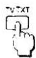
1.
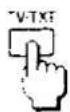
Push this button to select the "TEXT" mode.

Back to the TV mode.
Push the "TV/TEXT Selection" Button.
Note :
The first time that TELETEXT is selected after the TV is switched ON, the first page displayed is that stored in the red position in LIST mode.

Push this button, in "F.TEXT" Mode, to return to index page.
Depending on the way information is transmitted by each TV channel, this "INDEX" Button may need to be pushed more than once to return to the main index page.

flowchart
graph LR
    A["Table with TEXT TEXT"] -->|INDEX| B["MASTER INDEX"]
    B --> C["INDEX"]
    C --> D["DESIRED TEXT PAGE"]
    D -->|e.g. Push Red Button| B
    B -->|e.g. Push Cyan Button| C
    C -->|e.g. Push Red Button| B
    B -->|e.g. Push Cyan Button| C
    C -->|e.g. Push Cyan Button| D
Note :
"F.TEXT" Mode access, refer to page 73 to 74.

To select the required page of TELETEXT, use these buttons "0" to "9".
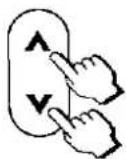
Push page Number Up "^" Button to step up to the next TELETEXT page. Push page Number Down "∨" Button to step down to the before TELETEXT page.
Note :
Page numbers always have three digits, the first being between 1 and 8 inclusive.

This function is used when characters on the TV screen are hard to read. Pushing 1st time expands the upper half of the screen only. Pushing 2nd time expands the lower half of the screen only. Pushing 3rd time returns the display to its original size (Full page).

flowchart
graph LR
    A["Heart Shape"] --> B["Hand-drawn Heart Shape"]
    B --> C["Hand-drawn Heart Shape"]
    C --> A
Note :
When the next page is selected under the upper/lower display expanded conditions, the upper half of the next page is expanded for display.
Fast Text (F.TEXT) mode access
In "F.TEXT" mode, select the desired teletext information by pushing one of the "Colour-Coded" Buttons on the remote controller which corresponds with the coloured subject's title on the screen.

(Teletext must be selected)
Push the "List/F.TEXT" Button to select the "F.TEXT".

e.g. Now, the on-screen display appear these subject's titles.

2.


e.g.
To view a "Weather" page, push the "Yellow" Button on the remote controller.
3.
Follow similar procedure to access other pages of teletext.
Note :
Subject's titles and their sequence for access are set-up by TV broadcast channels, they are not user's definable with the remote controller. It is a convenient way of accessing some Teletext pages without the need to enter page number.
Helpful Hint
4.

To return to index page, push the "INDEX" Button. For "INDEX" details, refer to page 72.
List mode access

In this mode, 4 page numbers can be preset in each programme position 1 to 25. A maximum of 100 pages can be programmed.
Any one of these 4 pages can be displayed instantly by pushing the corresponding "colour coded" Button on the Remote Controller.

(Teletext must be selected.)
Select the "LIST" Mode by using this button.
Push this button "LIST/F.TEXT" in "LIST" Mode to change from "F.TEXT" Mode and vice versa.
The on-screen display will be changed as follows.


To select the memory position, push one of the "colour-coded" Buttons.
3 | Enter the page number of the desired text, by using buttons "0" to "9" or "Programme Up or Down" Buttons. | |
| 4. | Repeat steps 2 and 3 for the remaining positions if required. Up to 4 page numbers can be preset in each programme position 1 to 25. | |
5. | To store these page numbers into memory, push the "LIST STORE" Button and hold until the background of the 4 numbers change from Black to White. | |
| 6. | Every time "LIST" Mode is selected, these 4 page numbers will flash until all 4 pages have been found and stored into memories.Any one of these 4 pages can be displayed instantly by pushing the corresponding "colour coded" Button on the Remote Controller. | |
| Note:(1) If a new page number is entered for viewing, it will not replace the previous number in the memory at that position unless the "LIST STORE" Button is pushed and kept pushing for a few seconds.The 4 page numbers will be reset to the preset numbers when either the "RESET" Button is pushed or programme position is changed, or mode once changed to F.TEXT then returns to list mode again, or TV set is turned off.(2) The 4 preset page numbers can be changed when required, by above procedures 2 to 5.(3) Page numbers preset can only be performed with programme number 1 to 25. | ||
| Helpful Hints | ||
[0xCT] | When this button is pushed, the TV set will change TV mode to TEXT mode.This button allows user to direct access to the page stored on "CYAN" key for that programme.Method:1. List mode must be entered in each programme number position.2. The page number must be stored in the "CYAN" position. | |
8. | Push this button in the "F.TEXT" mode will reset the present page back to page 100 and associated colour subject.Push this button in the "LIST" mode reset the present page to the "Red" coloured page number. | |
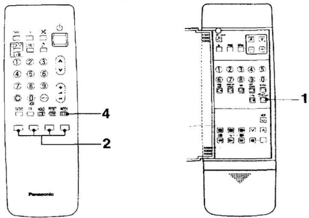
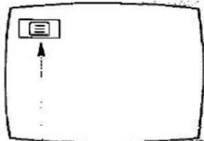
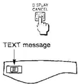
Display Cancel Operation

(Teletext must be selected.)

While a selected page is being searched for, TV picture can be viewed by pushing this button.
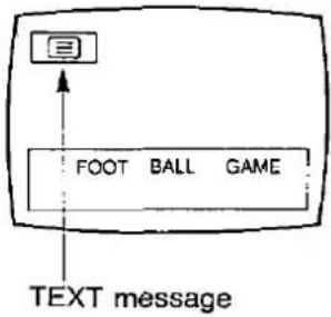
When that page is found, the "TEXT" message will appear in the top left corner of the screen.
Then push twice the "TV/TEXT Selection" Button to have the display of selected page on the screen.
flowchart
graph TD
    A[" "] --> B["..."]
    style A fill:#fff,stroke:#000
    style B fill:#fff,stroke:#000
Text message
| Method (To watch a newsflash page) | |
| 1. | In text mode, select a newsflash page.e.g. Page No. 155 |
| [GSDG] | |
| 2. | After reading the articles on the newsflash page, push the “DISPLAY CANCEL” Button.The TV switches from the Text page screen to TV picture.Every time an updated newsflash information is available, the newsflash information will be displayed at the bottom of the screen.When that page is found, a message will be displayed in the Top left corner of the screen. |
| [AHWS] | |
 | |
| 3. | To turn the Text page, push the “TV/TEXT Selection” Button twice. |
 | |
Text Sub page access
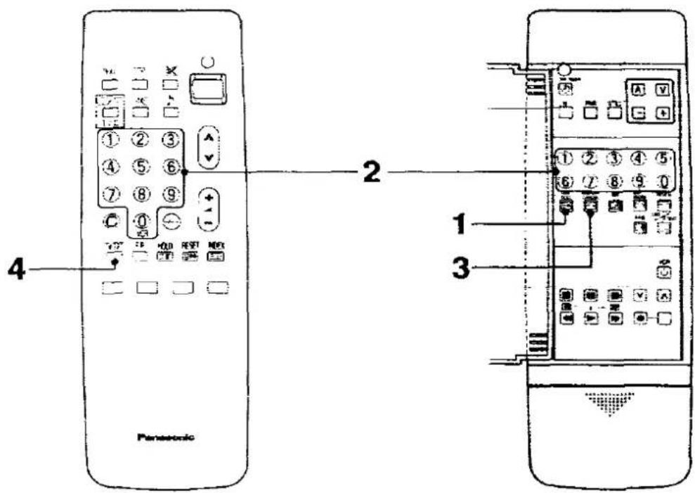
When Teletext information exceeds one page, it may take some time for the automatic changing of the sub-pages to reach the sub-page you require.
It is possible to enter your required sub-page and continue watching the normal programme unit the correct sub-page is found.
1.

Required Teletext page must be selected.
Push the "TIME TEXT" Button.
TXXXX
At that time, "Txxxx" will be displayed at the top left of the screen.

flowchart
graph TD
    A["Hand 0"] --> B["Hand 0"]
    B --> C["Hand 6"]
    C --> D["T0006"]
    D --> E["Button T0006"]
Enter the desired sub-page number before the "Txxxx" disappear. If you select sub-page 6 then you must push 0, 0, 0 and 6 buttons.
If in "LIST" mode, the letter "T" will appear in the current coloured box at the bottom of the screen indicating that the subcoded has been set.
Push the "DISPLAY CANCEL" Button to view a normal TV programme.
When the desired sub-page is found, the "TEXT" message will appear at the top left of the screen.
Push the "TV/TEXT" Selection Button twice to display the found sub-page.
To clear the sub-coded page. enter a new page number or press "RESET" Button.
Note :
It is not possible to select another programme during sub-page operation.
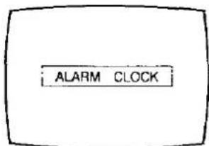
Text ALARM Page access
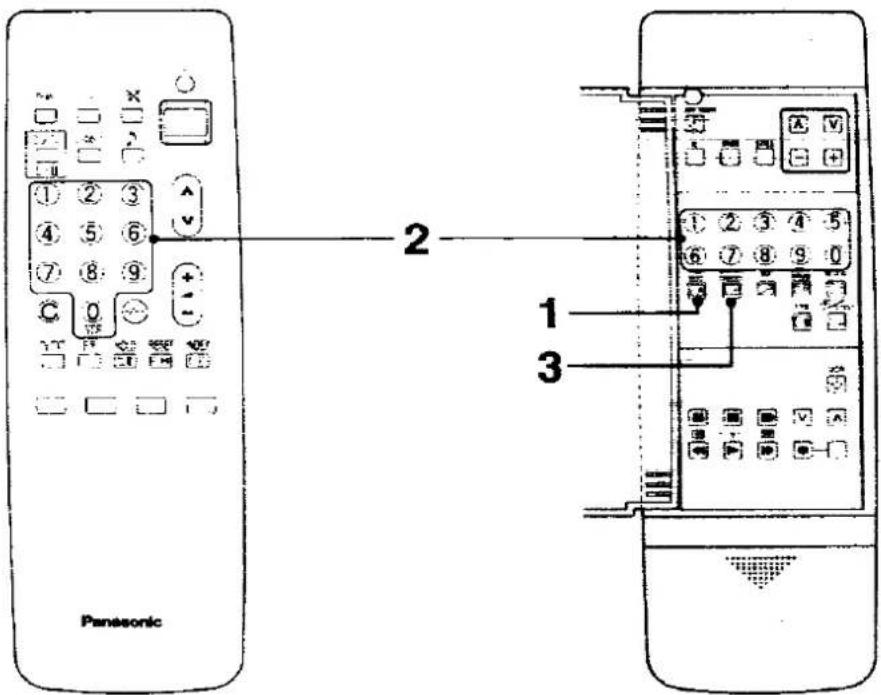

(Teletext must be switched on.) This function is used for selected pages only.
e.g. The Teletext ALARM page.
Refer to the subject index page for page location.
Method
1.

Text ALARM Page must be selected.
Push the "TIME TEXT" Button.
TXXXX
At that time, "Txxxx" will be displayed at the top left of the screen: now enter the time at which this alarm page should be displayed using buttons 0 to 9 on the remote control.

flowchart
graph TD
    A["1"] --> B["2"]
    C["3"] --> D["4"]
    E["5"] --> F["6"]
    G["0"] --> H["7"]
    I["T1530"] --> J["Bottom Timer Input L XXXT 200 300 400"]
This feature uses a 24 hour clock. e.g. To set the alarm for 3:30 p.m.
Push buttons 1, 5, 3, 0 consecutively, the Txxxx display will change to "T1530" momentarily then return to the current page number.
If in "LIST" mode, the letter "T" will appear in the current coloured box at the bottom of the screen indicating that the alarm page has been set.

Push the "DISPLAY CANCEL" Button to view TV.
At 3:30 p.m. the alarm page will be displayed.
To cancel this feature
Push the "TV/TEXT Selection" Button to return to normal viewing, the "TV/TEXT Selection" Button if you wish to select other teletext pages or push the "RESET" Button.

These functions can be used in both 2 types Teletext systems
1.

Pushing this button in the "F.TEXT" mode will reset the present page back to page 100 and associated colour subject. Pushing this button in the "LIST" mode resets all colored numbers back to the initial coloured page numbers (the page numbers memorized by "LIST STORE" Button) and then Red coloured page number is selected.
2-1.

Push this button, the Teletext page appears over the TV programme.

natural_image
Simple line drawing of a butterfly with shaded petals and marked points (no text or symbols)2-2.

Back to the TV mode. Push the "TV/TEXT Selection" Button.
3.


The selected page may have been divided into subpages. These subpages are rotated automatically on the screen.
Push this button, the subpage will stay on the screen.
The "Hold" message will be displayed in the top left corner of the screen.

To cancel the "Hold", push this button again.
4.

Some pages contain concealed information. e.g. the solution to a riddle or a puzzle. Push the "REVEAL" Button, the concealed information appears.
To switch off the concealed information, push this button again.
Operation for VCR
This infrared remote control is designed specifically to be used with selected Panasonic VCRs. Some model VCRs have different functions, so please refer to the individual instruction booklet to ensure compatibility when using this remote controller with Panasonic VCRs, consult your dealer for details.
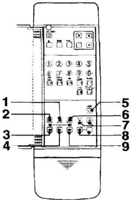
1.

Pause / Still Button
Push to stop the tape temporarily during playback or recording. A still-picture will be shown.
2.

Stop Button
Push this button to stop the tape.
3.

Rew (Rewind) / Review Button
Push this button to rewind the tape.
During the playback mode, holding this button down will allow you to view the picture in fast reverse motion. (Review)
| 4. |  | Play ButtonPush this button to playback the tape. |
| 5. | 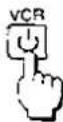 | VCR Power ButtonPush this button to turn the VCR on.Push again to turn off. |
| 6. |  | Still Advance ButtonWhile in the still mode, push this button to advance the picture one frame at a time. |
| 7. |  | Programme Number Up and Down Button for VCRPush the Programme Number "Up" or "Down" Button to select a programme position which you want to tune to a TV station. |
| 8. |  | Rec (Record) ButtonsRecording is started by pushing these 2 buttons at the same time. |
| 9. |  | FF (Fast Forward) / Cue ButtonPush this button to fast forward the tape.During the playback mode, holding this button down will allow you to view the picture in the forward direction rapidly. (Cue) |
Power Source and TV System
This TV set can be operated on AC 240 V, 50 Hz. It is designed exclusively for broadcast systems PAL I (U.K. Standard).
To prevent damage which may result in fire or electrical shock hazard, do not expose the TV set to rain or excessive moisture.
High Voltage:
Do not remove the rear cover as live parts are accessible when it rear cover is removed.
Adequate ventilation is essential to prevent failure of electrical components.
Avoid exposing the TV set to direct sunlight and other sources of heat.
Remove the plug from the wall outlet (Power point) when the TV set is not used for a prolonged period of time.
Cabinet and Picture Tube Care
The cabinet and picture tube can be kept in good condition by simply wiping with a clean, soft cloth moistened with mild detergent and water. Do not use solutions containing benzol, petroleum or a chemical cloth. For safety, remove the plug from the wall outlet.
Do not used this set if abnormal operation occurs.
Ex : Smoke, odd sounds, or smells Turn the power switch off and disconnect the AC plug, if you notice any unusual operation.

- 2017年,公司与上海浦东发展银行股份有限公司签订了《关于使用部分闲置募集资金进行现金管理的协议》。

bar
| Category | Value | |---|---| | Category 1 | 88 | | Category 2 | 70 | | Category 3 | 65 | | Category 4 | 60 | | Category 5 | 55 | | Category 6 | 50 | | Category 7 | 45 | | Category 8 | 40 | | Category 9 | 35 | | Category 10 | 30 | | Category 11 | 25 | | Category 12 | 20 | | Category 13 | 15 | | Category 14 | 10 | | Category 15 | 5 | | Category 16 | 0 | | Category 17 | 0 | | Category 18 | 0 | | Category 19 | 0 | | Category 20 | 0 | | Category 21 | 0 | | Category 22 | 0 | | Category 23 | 0 | | Category 24 | 0 | | Category 25 | 0 | | Category 26 | 0 | | Category 27 | 0 | | Category 28 | 0 | | Category 29 | 0 | | Category 30 | 0 | | Category 31 | 0 | | Category 32 | 0 | | Category 33 | 0 | | Category 34 | 0 | | Category 35 | 0 | | Category 36 | 0 | | Category 37 | 0 | | Category 38 | 0 | | Category 39 | 0 | | Category 40 | 0 | | Category 41 | 0 | | Category 42 | 0 | | Category 43 | 0 | | Category 44 | 0 | | Category 45 | 0 | | Category 46 | 0 | | Category 47 | 0 | | Category 48 | 0 | | Category 49 | 0 | | Category 50 | 0 | | Category 51 | 0 | | Category 52 | 0 | | Category 53 | 0 | | Category 54 | 0 | | Category 55 | 0 | | Category 56 | 0 | | Category 57 | 0 | | Category 58 | 0 | | Category 59 | 0 | | Category 60 | 0 | | Category 61 | 0 | | Category 62 | 0 | | Category 63 | 0 | | Category 64 | 0 | | Category 65 | 0 | | Category 66 | 0 | | Category 67 | 0 | | Category 68 | 0 | | Category 69 | 0 | | Category 70 | 0 | | Category 71 | 0 | | Category 72 | 0 | | Category 73 | 0 | | Category 74 | 0 | | Category 75 | 0 | | Category 76 | 0 | | Category 77 | 0 | | Category 78 | 0 | | Category 79 | 0 | | Category 80 | 0 | | Category 81 | 0 | | Category 82 | 0 | | Category 83 | 0 | | Category 84 | 0 | | Category 85 | 0 | | Category 86 | 0 | | Category 87 | 0 | | Category 88 | 0 | | Category 89 | 0 | | Category 90 | 0 | | Category 91 | 0 | | Category 92 | 0 | | Category 93 | 0 | | Category 94 | 0 | | Category 95 | 0 | | Category 96 | 0 | | Category 97 | 0 | | Category 98 | 0 | | Category 99 | 0 | | Total (Total) = [sum of the first bar (Category) + total (Category + category) * sum of the other bars (Category + category)]Troubleshooting
| Before you call for service, determine the symptoms and make a few simple checks as shown below. | ||||
| Symptoms | Checks | |||
| Picture | Sound | |||
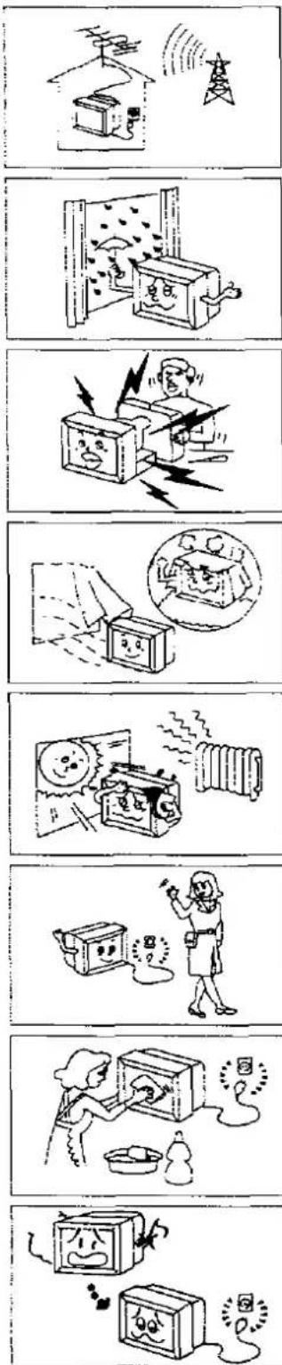
 |  | Aerial Location, direction or Connections | ||
| Snowy Picture | Noisy Sound | |||
 |  | Aerial Location, direction or Connections | ||
| Multiple Image | Normal Sound | |||
 |  | Electrical Appliances Cars / Motorcycles Fluorescent Lamps | ||
| Interference | Noisy Sound | |||
 |  | Speaker select switch Volume (Check whether the mute function has been) activated on the Remote Control. | ||
| Normal Picture | No Sound | |||
 |  | Not plugged into AC outlet Not switched on Contrast and Brightness / Volume setting (Check by pushing the Power Switch or (Stand-by) Button on the Remote Control | ||
| No Picture | No Sound | |||
 |  | Colour Control | ||
| No Colour | Normal Sound | |||
 |  Normal or Weak Sound Normal or Weak Sound | Return Channels | ||
| Scrambled | ||||
 |  | Magnetic interference from unshielded equipment Receiver moved while "ON" (Power switch off for 10 mins.) | ||
| Coloured Patches | Normal Sound | |||
 |  |  |  | Colour System |
| No Colour | Rolling Picture | H-Line | Noisy Sound | |
Troubleshooting for the Satellite Broadcasting
| Symptoms | Causes | Countermeasures |
Picture does not appear. Noise is evident.  | Error in the direction of the Dish Aerial and / or malfunction of the aerial cable are possible causes. Damping of the signal can be caused by accumulation of snow on the aerial, rain, thunder-storm or vibration due to strong winds. | Consult with your local dealer. Signals of a satellite broadcast are deteriorate during thunder-storm or heavy rainfall. Reception condition grow worse when snow accumulates on the aerial causing temporary disappearance of the picture and interruption of the sound. In certain conditions, no signal is received. Such symptoms are caused by the weather and not due to malfunction of the satellite broadcast receiver. |
No picture and no sound.   | Has the “LNB” Power Switch been set to “OFF”? Sometimes, the broadcasts are off the air. | Set the “LNB” Power Switch to the “ON” position. When the sun, earth, and the satellite are aligned with the latter being behind the earth, sunlight does not reach the solar batteries of the satellite, and thus signal emission from the satellite is suspended.  |
| TV sound is not heard. | Error in selecting the audio mode. | Select the correct audio mode. |
Receiving Satellite : AS-1A
| Channel | Programme | Frequency GHz | Pol. |
| 1 | Screensport | 11.21425 | H |
| 2 | RTL | 11.22900 | V |
| 3 | TV 3 | 11.24375 | H |
| 4 | Eurosport | 11.25850 | V |
| 5 | Lifestyle / Childrens Channel / J.S.T.V. | 11.27325 | H |
| 6 | SAT 1 | 11.28800 | V |
| 7 | TV1000 | 11.30275 | H |
| 8 | Sky 1 | 11.31750 | V |
| 9 | Teleclub | 11.33225 | H |
| 10 | 3 SAT | 11.34700 | V |
| 11 | Filmnet | 11.36175 | H |
| 12 | Sky TV News | 11.37650 | V |
| 13 | RTV Veronique | 11.39125 | H |
| 14 | PRO 7 | 11.40600 | V |
| 15 | MTV EUROPE | 11.42075 | H |
| 16 | Sky Movies/ The shopping channel | 11.43550 | V |
Note : These channels maybe subject to future alteration.
Receiving Satellite : AS-1B, AS-1C
| AS-1B | AS-1C | |||||
| Channel | Programme | Frequency GHz | Pol. | Programme | Frequency GHz | Pol. |
| 1 | Non | 11.46425 | H | Non | 10.96425 | H |
| 2 | Non | 11.47900 | V | Non | 10.97900 | V |
| 3 | Non | 11.49375 | H | Non | 10.99375 | H |
| 4 | Non | 11.50850 | V | Non | 11.00850 | V |
| 5 | Non | 11.52325 | H | Non | 11.02325 | H |
| 6 | Non | 11.53800 | V | Non | 11.03800 | V |
| 7 | Non | 11.55275 | H | Non | 11.05275 | H |
| 8 | Non | 11.56750 | V | Non | 11.06750 | V |
| 9 | Non | 11.58225 | H | Non | 11.08225 | H |
| 10 | Non | 11.59700 | V | Non | 11.09700 | V |
| 11 | Non | 11.61175 | H | Non | 11.11175 | H |
| 12 | Non | 11.62650 | V | Non | 11.12650 | V |
| 13 | Non | 11.64125 | H | Non | 11.14125 | H |
| 14 | Non | 11.65600 | V | Non | 11.15600 | V |
| 15 | Non | 11.67075 | H | Non | 11.17075 | H |
| 16 | Non | 11.68550 | V | Non | 11.18550 | V |
Receiving Satellite : DBS
| Channel | Programme | Frequency GHz | Channel | Programme | Frequency GHz |
| 1 | Non | 11.72748 | 21 | Non | 12.11108 |
| 2 | Non | 11.74666 | 22 | Non | 12.13026 |
| 3 | Non | 11.76584 | 23 | Non | 12.14944 |
| 4 | Non | 11.78502 | 24 | Non | 12.16862 |
| 5 | Non | 11.80420 | 25 | Non | 12.18780 |
| 6 | Non | 11.82338 | 26 | Non | 12.20698 |
| 7 | Non | 11.84256 | 27 | Non | 12.22616 |
| 8 | Non | 11.86174 | 28 | Non | 12.24534 |
| 9 | Non | 11.88092 | 29 | Non | 12.26452 |
| 10 | Non | 11.90010 | 30 | Non | 12.28370 |
| 11 | Non | 11.91928 | 31 | Non | 12.30288 |
| 12 | Non | 11.93846 | 32 | Non | 12.32206 |
| 13 | Non | 11.95764 | 33 | Non | 12.34124 |
| 14 | Non | 11.97682 | 34 | Non | 12.36042 |
| 15 | Non | 11.99600 | 35 | Non | 12.37960 |
| 16 | Non | 12.01518 | 36 | Non | 12.39878 |
| 17 | Non | 12.03436 | 37 | Non | 12.41796 |
| 18 | Non | 12.05354 | 38 | Non | 12.43714 |
| 19 | Non | 12.07272 | 39 | Non | 12.45632 |
| 20 | Non | 12.09190 | 40 | Non | 12.47550 |
Note :
1. Non = Not allocated
2. Reception of satellite programmes is dependent on the type of transmission.
Specifications
Specifications for TV system
Power Source
AC 240 V, 50 Hz
Power Consumption
325 W
Stand-by condition 10 W
Receiving System
| System | Remark |
| PAL I | Reception of broadcast andPlayback from Video Tape Recorders |
| NTSC 4.43/5.5 MHzNTSC 3.58/5.5 MHz | Playback from Video Tape Recorders |
Receiving Channels
UHF 21 - 69
Tuning System
Frequency synthesized
Picture Tube
37 inches (89 cm) measured diagonally, 110° deflection
Aerial Impedance
75 Ω Unbalanced coaxial
Audio Output
Internal Speaker 15 W (Max.) × 2 Impedance 8 Ω External Speaker 35 W (Max.) × 2 Impedance 4 Ω - 8 Ω
Headphones
Impedance 8 Ω
Video / Audio Terminals
| AV1 IN | Video (Euro AV) 1 Vp-p 75 ΩAudio (Euro AV) 0.5 Vrms, 10 KΩ |
| AV1 OUT | Video (Euro AV) 1 Vp-p 75 ΩAudio (Euro AV) 0.5 Vrms, (80 % modulation) 1 KΩ |
| AV2 IN | S-Video Y : 1.0 Vp-p 75 ΩC : 0.3 Vp-p 75 ΩAudio (RCA) 0.5 Vrms, 10 KΩVideo (Euro AV) 1 Vp-p 75 ΩAudio (Euro AV) 0.5 Vrms, 10 KΩ |
| AV2 OUT | Video (Euro AV) 1 Vp-p 75 ΩAudio (Euro AV) 0.5 Vrms, (80 % modulation) 1 KΩ |
| AV3 IN | S-Video Y : 1.0 Vp-p 75 ΩC : 0.3 Vp-p 75 ΩVideo (RCA) 1 Vp-p 75 ΩAudio (RCA) 0.5 Vrms, 10 KΩ |
Specifications for Satellite Broadcasting
This Satellite Broadcasting System can not used in other country as designed for U.K. only.
Receiving Local Frequency
| AS - 1A 10 GHz |
| AS - 1B 10 GHz |
| AS - 1C 10 GHz |
| DBS 10.75 GHz |
Receiving System
| ASTRA 1a |
| ASTRA 1b |
| ASTRA 1c |
| DBS |
Receiving Channels
| Satellite | Channel |
| ASTRA 1a | 1 - 16 |
| ASTRA 1b | 1 - 16 |
| ASTRA 1c | 1 - 16 |
| DBS | 1 - 40 |
Input Terminals
| IF In | F-type receptacle (75 ohms);950 — 1750 MHz(15 V DC output for LNB power, with On / Off switch) |
Output Terminals
| Video | RCA phono pin type1.0 V p-p. 75 ohms (PAL-Video) |
| Audio | RCA phono pin type |
| mode 1 — mode 6 | 1.0 Vrms at 100 % modulation(50 kHz peak deviation) |
| mode 7 | 0.75 Vrms at 100 % modulation(85 kHz peak deviation) |
| Decoder | Euro 21-pin type |
| Polarizer : | Ferro-feed ± 45^ type |
LNB Power
3.5 W max. 15 V
Polarizer Output
±35 mA (Typ.)
Specifications
Accessories Supplied
Remote controller × 1 R6 Battery × 2
Dimensions (W × D × H)
940 × 610 × 758 mm
Mass (Weight)
101.0 Kg (Net)
Note :
Design and Specifications are subject to change without notice. Weight and Dimensions shown are approximate.
TV Games and Home Computers
The extended use of TV Games and Home Computers with any television set can cause a permanent "shadow image" on the picture tubes. This background image is viewable on normal programmes in the form of the stationary TV Game and Home Computer objects. This type of irreversible damage to the picture tubes that TV Games and Home Computers cause, can be limited by observing the following steps.
- Reduce the brightness/contrast setting to a minimum viewing level during TV Game and Home Computer operation.
- Do not operate the television set with TV Games and Home Computers continuously for extended periods of time.
- Be sure to turn the television set off when not actually using it. The marking image on the picture tube resulting from excessive TV Game and Home Computer use is not an operation defect and is as such not covered by Panasonic U.K. Ltd.'s Warranty. Television sets are not designed to display TV Game and Home Computer patterns continuously for extended periods of time.
641
Customer's Record
The serial number of this product may be found on its rear cover. You should note the number of this unit in the space provided and retain this book as a permanent record of your purchase to aid in identification in the event of theft or loss.
Model Number
TX-37A2G
Serial Number
Matsushita Electric Industrial Co., Ltd.
Central P.O. Box 288, Osaka 530 - 91, Japan
Printed in Japan
S1290
- Panasonic
- Operating Instructions
- Dear Panasonic Customer
- IMPORTANT
- Contents
- Connection
- Basic Operation on the Remote Controller 47
- General Operation on the Remote Controller 49
- 0/VCR Button Operation 63
- General Operation of the Satellite Broadcasting 65
- Basic Operation of Teletext 71
- Teletext Operation
- Operation for VCR 85
- Warnings and Cautions 87
- Troubleshooting 89
- Channel Allocation of Satellite Broadcasting 91
- Specifications 93
- Before operating this set
- Preparations
- Connect the Aerial Cable to the Terminals
- Connect the Plug to the Wall outlet
- Adjust the Magnetism Correction
- Batteries : Use two "R6" size alkaline batteries
- 1.
- 2.
- 3.
- Battery precautions
- How to open the door on the rear of Remote Control
- How to Open the Controls Panel
- Location of Controls on the TV set
- Power Switch
- Location of Controls of the Remote Control
- No. Description
- Power (Stand-by) Button
- Location of Terminals
- Connection of the Euro AV1 Terminals
- Connection of the Euro AV2 Terminals
- Connection of Decoder Terminals
- How to Connect an Aerial
- Note :
- Satellite Aerial Connection
- Operation
- Decoder Connection
- Decoder Operation
- How to Adjust the Magnetism Correction
- Pattern 1 : Via the "AV1" Euro AV Terminal
- 2-2.
- Pattern 2 : Via the "AV2" Euro AV Terminal
- Pattern 3 : Via the "AV2" S-Video and Audio Terminals
- Helpful Hint : Tuner / Monitor Out Switch
- Pattern 4 : Via the "AV3" S-Video and Audio Terminals
- Pattern 5 : Via the "AV3" Video and Audio Terminals
- Connecting the external Speakers
- Connect the external Speakers as follows.
- Connecting the Headphones
- Helpful Hint
- 4.
- 1-1.
- 1-2.
- Tuning of the Satellite Broadcasting
- 5.
- 6.
- 7.
- Basic Operation on the TV set
- Programme Number Up / Down Operation
- Volume Up / Down Operation
- General Operation on the TV set
- To adjust the Video menu
- To adjust the Audio menu
- To adjust the Balance
- Basic Operation on the Remote Controller
- General Operation on the Remote Controller
- Operating Video Menu
- Helpful Hint :
- Operating Audio Menu
- Helpful Hint:
- 3-1.
- 3-2.
- 8.
- 9.
- To Cancel the Still picture
- Method
- General Operation of the Satellite Broadcasting
- 2-1.
- 3-3.
- Satellite Mode Switch Operation
- OFF Position
- ON Position
- Unsupervised Recording mode
- Basic Operation of Teletext
- Text Sub page access
- To cancel this feature
- These functions can be used in both 2 types Teletext systems
- Operation for VCR
- Power Source and TV System
- High Voltage:
- Cabinet and Picture Tube Care
- Troubleshooting
- Specifications
- Specifications for TV system
- Power Source
- Power Consumption
- Receiving Channels
- Tuning System
- Picture Tube
- Aerial Impedance
- Audio Output
- Headphones
- Specifications for Satellite Broadcasting
- LNB Power
- Polarizer Output
- Accessories Supplied
- Dimensions (W × D × H)
- Mass (Weight)
- TV Games and Home Computers
- Customer's Record
Kaubamärk : PANASONIC
Mudel : TX-37A2G
Kategooria : Teler