LSS-100P - Electronic sensor USL - Free user manual and instructions
Find the device manual for free LSS-100P USL in PDF.


| Brand | USL |
| Model | LSS-100P |
| Product Type | Power Adapter |
| Input Voltage | 100-240V AC |
| Input Frequency | 50/60Hz |
| Output Voltage | 12V DC |
| Output Current | 2A |
| Output Power | 24W |
| Connector Type | DC Barrel Jack |
| Cable Length | 1.5 m |
| Dimensions (L x W x H) | 100 x 50 x 30 mm |
| Weight | 200 g |
| Operating Temperature | 0°C to 40°C |
| Storage Temperature | -20°C to 60°C |
| Humidity | 5% to 95% non-condensing |
| Protection | Overcurrent, overvoltage, short circuit |
| Efficiency | >85% |
| Safety Certifications | CE, RoHS |
| Color | Black |
| Material | ABS plastic |
| LED Indicator | Power on |
| Package Contents | Adapter, user manual |
| Warranty | 1 year |
Frequently Asked Questions - LSS-100P USL
User questions about LSS-100P USL
0 question about this device. Answer the ones you know or ask your own.
Ask a new question about this device
Download the instructions for your Electronic sensor in PDF format for free! Find your manual LSS-100P - USL and take your electronic device back in hand. On this page are published all the documents necessary for the use of your device. LSS-100P by USL.
USER MANUAL LSS-100P USL
Installation and Operation Manual

Table of Contents
Table of Contents 2
Introducon....3
Features 4
Firmware Version 6
Installaon....6
Installaon....12
NTP, IR, and Luminance Check....13
Wring Command Scripts 13
Script Test Run....15
Data Analysis.... 15
CSV Data Use 16
Mulple Logs on One Page 17
Mulple Auditorium Summary....18
Ethernet Device Discoverer Windows version....18
Ethernet Device Discoverer iOS version....19
Ethernet Device TCP Based Operaons 19
TCP_Send Command Usage 22
CP850 Control 22
Log Post XML Format 23
LSS-DB 24
Hidden Screens.... 24
View Conguration Data....24
Calibraon Screens....24
Firmware Update 26
Restore Buon 26
Useful Soware.... 27
Ethernet Device Discoverer....27
LSS Database Soware....28
Appendix A – Red/Green Flash Script Start 29
Appendix B – USB Power Interface and Contact Closure Script Start.... 30
Appendix C – Language Support.... 31
Product Support 32
Warranty....32
Manual Revision History 32
Introducon
The LSS-100P is designed for cinema auditorium quality control. It measures C-weighted sound pressure level (SPL) in dB, luminance in cd/m² and fL, chromacity (x and y), and correlated color temperature. The LSS-100P makes all of these measurements available on a web interface, through TCP commands over Ethernet, and by posng data to a remote web server for further analysis and display.
In a typical installaon, the digital cinema server runs a test show each day. The show consists of a composition containing red and green ashes that tell the LSS-100P to run one of its scripts. The script start composition is followed by a test composition. Several test composions are available for dierent auditorium conguraons. Each of these provide pink noise to each speaker in the auditorium. The LSS-100P measures the SPL from each speaker to detect changes in the system. The test composions also include a white test paern allowing the LSS-100P to measure peak luminance and chromacity. These values are limit checked, logged, and oponally posted to a remote web server for further analysis.
The LSS-100P contains a color sensor, not an image sensor. There is no possibility of the LSS-100P transming an image of the movie, so it does not present any security issues.
The LSS-100P is powered by the supplied Power Over Ethernet power injector. If desired, it may also be powered using a USB cable.
The LSS-100P should be mounted on the rear wall of the auditorium. It is aimed towards the center of the screen using the internal LEDs. Before the rst show or aer the last show, a test paern is projected and pink noise sent to each speaker. The LSS-100P measures the color, luminance, and SPL. These measurements are used to identify lamps nearing end of life, misadjusted lamps, projector color problems, defective speakers, etc.
Since measurements vary in dierent posions in the room, the measurements from the LSS-100P should be compared with previous measurements to detect changes rather than interpreng the absolute values delivered by the LSS-100P.
| LSS-100P Package Contents | |
| 1 | LSS-100P Unit |
| 1 | POE Power Injector |
| 1 | Wall / Ceiling Mount (2 pieces) |
| 1 | LSS-100P User Manual |
Features
- Luminance Measurement – Uses a precision detector with a photopic spectral response.
- Chromacity Measurement – Uses a precision RGB sensor and calculates XYZ, xy, and CCT.
- SPL Measurement – Uses a DSP generated C-weighing Iter and RMS detector for accurate results regardless of signal waveform or crest factor.
- IR Measurement – Measures relave IR illuminaon of screen to detect issues with IR emiers used for hearing impaired audio, visually impaired audio, or closed capons.
- Temperature Measurement – Includes an internal temperature sensor that can be used to approximate auditorium temperature and track changes.
- Web Interface – Displays live measured data along with user dened reference values. The web interface supports language translation tables based on the language requested by the browser. Currently the web interface supports English (en) and Chinese (zh).
- Automac Start Clips – Three Red/Green start clips packaged as DCPs that can automacally trigger user scripts in the LSS-100P.
- TCP Command Interpreter – Accepts commands over Ethernet to log data, send current measurement, start a measurement script, etc.
- Command Scripng – An unlimited number of user scripts (up to a total of 65,530 characters) may be dened. Scripng permits a sequence of measurements to be made automacally.
- Script Triggering – Scripts are typically triggered using a red/green ash sequence at the start of the test show. As an alternate, scripts may be started with a command over TCP or by a contact closure. See appendix ??? for informaon on alternate script start mechanisms.
- Logging with Limit Checking and Graph Generaon – The LSS-100P can capture measurements to a log. The log shows the measurement in red if it is outside user dened limits. The log can be downloaded as a CSV le for analysis in a spreadsheet. The LSS-100P generates graphs of logged data showing trends of the measured data along with limit lines.
- Web Services Posng – The LSS-100P can post log data to one or more HTTP or HTTPS servers. Log data is sent as XML for simple parsing into a database for report generaon. The USL provided LSS-DB can run on a user-provided server to gather informaon from a large number of LSS-100P devices and generate reports and alerts.
- Power Over Ethernet – The LSS-100P is powered by a POE enabled Ethernet switch or the supplied power injector. Use of POE simplifies installaon since fewer wires need to be run. The LSS-100P is an IEEE 802.3af class 1 powered device. It may be powered by “acve” (power sources that use the POE signature) or “passive” (power sources that do not use the standard POE signature) 48V POE injectors. The LSS-100P consumes less than 1.5W.
- USB Power – As an alternate, the LSS-100P can be powered by a USB power supply.

Figure 1- LSS-100P Home Page
| Record Number | UTC Time | GUI Time Pacific Standard Time | LSS Time PDT | Description | Measured Value |
| 2057 | Mon Jun 2 05:31:34 2014 | Sun Jun 1 22:31:34 2014 | Sun Jun 1 22:31:34 2014 | SPL Left Low | 62.8dBc |
| 2058 | Mon Jun 2 05:32:04 2014 | Sun Jun 1 22:32:04 2014 | Sun Jun 1 22:32:04 2014 | SPL Left Mid | 60.1dBc |
| 2059 | Mon Jun 2 05:32:34 2014 | Sun Jun 1 22:32:34 2014 | Sun Jun 1 22:32:34 2014 | SPL Left High | 78.9dBc |
| 2060 | Mon Jun 2 05:33:04 2014 | Sun Jun 1 22:33:04 2014 | Sun Jun 1 22:33:04 2014 | SPL Right Low | 63.4dBc |
| 2061 | Mon Jun 2 05:33:34 2014 | Sun Jun 1 22:33:34 2014 | Sun Jun 1 22:33:34 2014 | SPL Right Mid | 79.5dBc |
| 2062 | Mon Jun 2 05:34:04 2014 | Sun Jun 1 22:34:04 2014 | Sun Jun 1 22:34:04 2014 | SPL Right High | 77.9dBc |
| 2063 | Mon Jun 2 05:34:34 2014 | Sun Jun 1 22:34:34 2014 | Sun Jun 1 22:34:34 2014 | SPL Center Low | 79.4dBc |
| 2064 | Mon Jun 2 05:35:04 2014 | Sun Jun 1 22:35:04 2014 | Sun Jun 1 22:35:04 2014 | SPL Center Mid | 79.5dBc |
| 2065 | Mon Jun 2 05:35:34 2014 | Sun Jun 1 22:35:34 2014 | Sun Jun 1 22:35:34 2014 | SPL Center High | 61dBc |
| 2066 | Mon Jun 2 05:36:04 2014 | Sun Jun 1 22:36:04 2014 | Sun Jun 1 22:36:04 2014 | SPL LFE | 63.1dBc |
| 2067 | Mon Jun 2 05:38:34 2014 | Sun Jun 1 22:38:34 2014 | Sun Jun 1 22:38:34 2014 | SPL Ls | 67.3dBc |
| 2068 | Mon Jun 2 05:37:04 2014 | Sun Jun 1 22:37:04 2014 | Sun Jun 1 22:37:04 2014 | SPL Rs | 85.4dBc |
| 2069 | Mon Jun 2 05:37:34 2014 | Sun Jun 1 22:37:34 2014 | Sun Jun 1 22:37:34 2014 | SPL Lrs | 68.9dBc |
| 2070 | Mon Jun 2 05:38:04 2014 | Sun Jun 1 22:38:04 2014 | Sun Jun 1 22:38:04 2014 | SPL Rrs | 68.5dBc |
| 2071 | Mon Jun 2 05:38:04 2014 | Sun Jun 1 22:38:04 2014 | Sun Jun 1 22:38:04 2014 | Luminance | 61.9% |
| 2072 | Mon Jun 2 05:38:04 2014 | Sun Jun 1 22:38:04 2014 | Sun Jun 1 22:38:04 2014 | Color x | 0.317x |
| 2073 | Mon Jun 2 05:38:04 2014 | Sun Jun 1 22:38:04 2014 | Sun Jun 1 22:38:04 2014 | Color y | 9.1MPa |
| 2074 | Mon Jun 2.05.38.04.2014 | Sun Jun 1. ^ = ^ = ^ = ^ = ^ = ^ = ^ = ^ = ^ = ^ = ^ = ^ = ^ = ^ = ^ = ^ = ^ log_p | |||
Figure 2 - LSS-100P Log
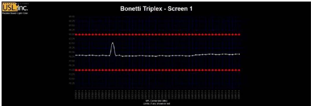
line
| SPL Carrier rated (dB) | Value | | --------------------- | ----- | | 69-74 | 80.00 | | 74-78 | 79.00 |Figure 3 - LSS-100P Graph
Firmware Version
The LSS-100P is subject to constant improvement. Check hp://p.uslinc.com/LSS-100P for the latest rmware. Note that the latest rmware can be used in both the LSS-100 and the LSS-100P. The LSS-100 does not have POE, the separate photopic sensor, contact closure script start, or the IR sensor. Otherwise, the units will behave the same with the latest rmware. See the Firmware Update secon for instrucons on updang the rmware.
Installaon
It is a lot easier to do the initial tesng of the LSS-100P on a table or the oor of the projecon booth instead of on top of a ladder.
-
Connect an Ethernet cable between the OUT connector of the supplied POE Power Injector and the LSS-100P. Connect another Ethernet cable from the IN connector of the POE Power Injector to a computer. Apply AC power to the POE Power Injector.
-
The green LED next to the Ethernet connector on the LSS-100P will light dimly for 30 seconds, then light brightly. During this me, the LSS-100P is checking its backup copy of the system rmware. The green LED is lit whenever the LSS-100P is powered unless the ash memory chip is being accessed (such as during the rmware check, loading or saving of conguraon informaon, etc.).
-
Open a web browser and type hp://169.254.1.6 in the address bar. On most laptops, this will bring up the home page of the LSS-100P. If it does not, try changing the laptop's IP address to 169.254.1.123 with a subnet mask of 255.255.0.0. Most laptops have automac crossover for Ethernet, but some older ones do not. If the LSS-100P home page is sll not visible, try using an Ethernet crossover cable between the laptop and the POE injector. The LSS-100P home page is shown below.

Figure 4 - LSS-100P Home Page
- Click on the "cong" to go to the Conguraon Page. The username is "admin" and the password is "ultra". There are several conguraon pages that are described below.
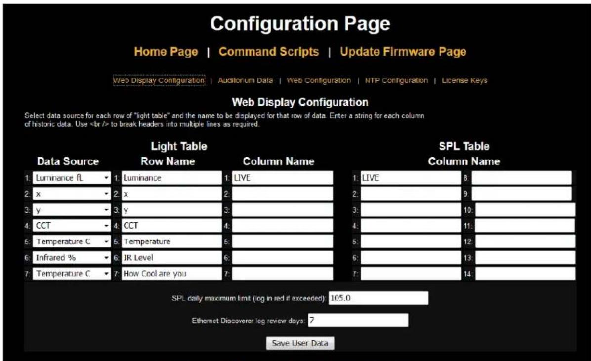
Figure 5 - LSS-100P Web Display Conguraon Page.
- The rst conguraon page, shown above, allows you to determine how the home page will appear. The Light Table secon determines how the le side of the home page will appear (the side that is showing luminance, color, etc.). The home page can show up to 7 rows of light informaon. The source of that informaon is set by the rst column of the light table. You can select U.S. or metric units for temperature and luminance. LSS-100P units with board revision F or higher also measure the relave IR illuminaon of the screen. This is useful for detectcng
issues with IR audio and caponing systems. Select the data source for each line of the home page light display.
- Set the name for each line of the home page light display. These may be in any language.
- The light table of the home page supports a total of 7 data columns. The rst column is always the current "live" measurement data. Additional columns hold reference measurements. Live data is copied to the reference measurement column by clicking on the header of the column on the home page. Dene a name for each of the data columns, The rst column is always labeled LIVE.
- The right side of this conguraon screen allows reference column names to be dened for the SPL measurement. These behave the same as the light reference measurements described in the previous step. Up to 14 SPL reference columns may be dened.
- The LSS-100P determines the highest SPL it measured from midnight local me to midnight local me. The highest value is logged each night at midnight. You can set a limit for the maximum SPL on this page. If this value is exceeded, the maximum SPL of the day will be shown in red on the log.
- The LSS-100P makes out of tolerance readings available to the USL Ethernet Device Discoverer (see hp://p.uslinc.com/?dir=p/Products/EthernetDeviceDiscoverer). Ethernet Device Discoverer “discovers” USL products on the network. In addition, it shows status messages from each device. If Etherernet Discoverer Log Review Days is set to 7 (as shown in gure 7), Ethernet Device Discoverer will display any out of tolerance readings logged in the past 7 days.
- Once this data has been entered, click the "Save User Data" buon to save the sengs to the LSS-100P.
- Click the "Auditorium Data" link at the top of the page.
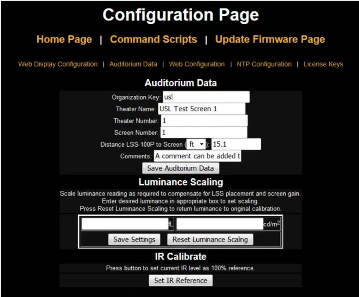
Figure 6 - LSS-100P Auditorium Data
-
Enter the theater name, theater number (large groups oen idenfy a parcular theater by number), and the screen or auditorium number. Note that the theater number and screen number must be numbers (not names). The “Organizaon Key” is used by the LSS Database soware to identify mulple theaters as part of company or organizaon. A parcular LSS-100P can be uniquely idened by the OrgKey, Theater Number, and Screen Number. The “Distance of LSS-100P to Screen” eld is used when running the audio/video sync check (coming soon). Additional informaon about the auditorium can be entered in the Comments eld. These comments show up on the home page and are reported in the XML web services log data. Click the “Save Auditorium Data” buon to save the data. Ignore the luminance scaling and IR Calibrate seconds for now.
-
Click the Web Conguraon link at the top of the page.
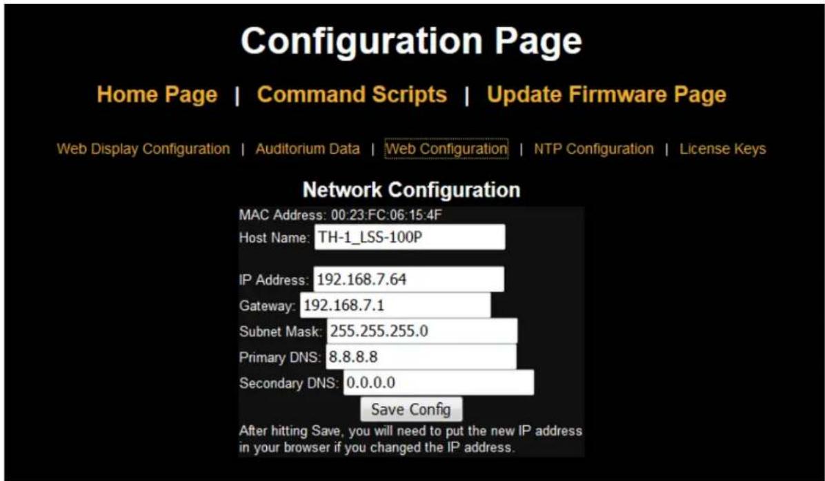
Figure 7 - LSS-100P Web Conguraon
- Enter the host name (NET BIOS host name), IP address, gateway, subnet mask, and DNS informaon. DNS is used if the NTP server or web services server (log posng in command scripts, CP850 test, etc.) is specied by a host name instead of an IP address. If IP addresses are used instead of host names, these elds can be le at 0.0.0.0. The default 8.8.8.8 is a DNS service provided by Google. Aer the network informaon has been entered, click the "Save Cong" buon to save the sengs. Note that the new IP address takes eect immediately, so it will be necessary to address the LSS-100P at its new address and will probably be necessary to change the laptop computer's IP address to an address on the same subnet.
- Click the NTP Conguraon link at the top of the page.

Figure 8 - LSS-100P NTP Conguraon
- An NTP server is required for the LSS-100P logging. Most digital cinema servers have an NTP server in them, so the IP address of that server can be entered. If outgoing internet access is available, the default seng of pool.ntp.org can be used. The NTP server IP address can be entered as a doed decimal IP address. If a DNS server was set up on the Web Conguraon screen, a domain name (such as pool.ntp.org) can be used instead.
- Set the me zone UTC oset. Osets for U.S. me zones are shown in gure 11. Note that fracons of an hour can be set (required for Venezuela, Afghanistan, India, Sri Lanka, Nepal, and other countries). Note that this is the oset for standard me, not advanced me, summer me, or daylight saving me. Additional me zone informaon is available at http://www.timeanddate.com/library/abbreviations/timezones/ and http://en.wikipedia.org/wiki/List_of_time_zones_by_UTC_offset.
| US Time Zone | UTC Offset | Standard Time Abbreviation | Daylight Saving Time Abbreviation |
| Hawaii-Aleutian | -10.0 | HAST | HADT |
| Alaska | -9.0 | AKST | AKDT |
| Pacific | -8.0 | PST | PDT |
| Mountain | -7.0 | MST | MDT |
| Central | -6.0 | CST | CDT |
| Eastern | -5.0 | EST | EDT |
Figure 9 - U.S. Time Zone Osets
- Enter the abbreviaons for standard and advanced, summer, or daylight saving me. Select whether daylight saving (or similar) is observed at the locaon the LSS-100P is installed. This seng is not whether DST is currently being observed, but whether it is ever observed. For example, in the U.S., this would be set to "no" for Arizona and "yes" for California. The LSS-100P displayed logs will take this into consideraon when displaying the me at the LSS-100P.
- Note that the boom line of this page shows the last me the LSS-100P clock was updated from the NTP server. Since the LSS-100P does not have access to an NTP server when it is only connected to your laptop, this will indicate that the last update was never.
- Click the License Keys link at the top of the page. License keys are required to enable certain advanced features in the LSS-100P. Contact USL to obtain a key for a parcular LSS-100P (the serial number of the LSS-100P will be required to issue the key. When a valid key is entered, the key turns green. An invalid key shows up in red. At this me, the only license key available enables control of the Dolby CP850 (enabling and disabling a test mode).

Figure 10 - License Key Conguraon Page.
Installaon
- Use the supplied OmniMount 10.0 wall mount to each the LSS-100P to the auditorium back wall. Aim the lens and microphone towards the screen. Thread the supplied nut onto the OmniMount threaded rod with the at side of the nut towards the threaded end and away from the ball. Thread the OmniMount threaded rod into the threaded hole on the LSS-100P turning the LSS-100P four turns, adjusting a fraction of a turn as required to point the LSS-100P towards the screen. Tighten the nut on the threaded rod against the LSS-100P case to rmly mount the LSS-100P to the threaded rod.
- If necessary, drill a hole between the booth and auditorium for the wiring. Since the LSS-100P uses Power Over Ethernet, only an Ethernet cable needs to be run. See Appendix ??? if USB power or contact closure script start is desired.
- Connect the Ethernet cable to the LSS-100P the supplied POE power injector OUT port. Connect another cable from the POE injector IN port to the auditorium Ethernet switch. If the auditorium has a POE enabled Ethernet switch, the Ethernet cable from the LSS-100P can be plugged directly into the switch.
- Turn the LSS-100P LED switch to on and adjust the focus control until the red spots on the screen appear to be in focus. As the LSS-100P is adjusted out of focus, the hole in the middle of the spots Ils in. When the LSS-100P is in focus, the hole in the center will be open and the edges sharp as shown in Figure 12. Once focus is set, lock the lens position by ghtening the thumb screw on the lens tube.
- Project the test paern on the screen. Suggested test content is the USL LST-100 DCP. It is available from USL on a USB ash drive or can be downloaded from hp://p.uslinc.com/?dir=p/Products/LSS-100P/Soware/TestContent. Posion the LED spots to be in the center of the test paern area. Since the projector lamp is much more powerful than the LEDs in the LSS-100P, it may be difficult to see the LED spots when the test paern is on. A simple method of seeing where the LED spots are within the test paern is to wave a hand through the projector beam, casng a shadow on the screen. As the shadow moves across the screen, the LED spots and their locaon within the test paern will become visible. The LSS-100P sensor is a linear sensor posioned midway between the LEDs. If the test paern is tall, adjust the LSS-100P to align the spots vertically. If the test paern is wide, rotate the LSS-100P to align the spots horizontally. Place the center of the area between the spots in the center of the test paern area. Lock the Omnimount posion and turn o the LEDs.

natural_image
Two bright glowing spots on a neutral gray background, no text or symbols visibleFigure 12 - LSS-100 LED Focus and aim.
- Turn on a pink noise source on one of the auditorium speakers (or play the test DCP which contains pink noise on each speaker in sequence). The SPL indicated by the LSS-100P should be close to that measured with an SPL meter. Again, due to system tolerances and variaons in sound level throughout the auditorium, the numbers will not match precisely.
NTP, IR, and Luminance Check
-
Go back to the NTP conguraon page (shown in gure 8) and ensure that the LSS-100P has received an NTP update.
-
If desired, the LSS-100P luminance measurement can be scaled to agree with a reference meter. The LSS-100P is factory calibrated, but, because it is not in the same locaon as a reference meter in the auditorium, it will probably read slightly dierent from the reference meter due to screen gain, elevaon of the projector above the screen center, etc. Project the test paern (ideally from the LST-100) and measure the luminance with the reference meter. While the test paern is sll present, key the measured luminance value into the appropriate box (cd/m ^2 or fL) in the Luminance Scaling secon of the Auditorium Data page (see gure 6). Click the “Save Sengs” buon to scale the LSS-100P luminance measurement to match the reference meter. You can click the “Reset Luminance Scaling” buon to return the LSS-100P to factory calibraon.
-
IR Calibrate also appears on the Auditorium Data page (board revision F and higher). Press the "Set IR Reference" buon when typical IR illuminaon of the screen is present. When the LST-100 test content plays, a USL UPC-28C emier transmits the hearing impaired and closed capon carriers, but not the visually impaired carrier. If you click the "Set IR Reference" buon when the LST-100 content is playing, the LSS-100P will set this level to 100%. The LSS-100P will read about 75% if only one IR carrier is present. It will read about 117% if all 3 carriers are present.
Wring Command Scripts
The LSS-100P script denion page includes default scripts. These can be copy and pasted into the script denion window. This secon covers running the test DCP and conguring limits on the scripts.
-
Download the LSS-100P test content from hp://p.uslinc.com/?dir=p/Products/LSS-100P/Soware/TestContent. The README.txt le describes the test content and provides sample scripts.
-
There are three ways that a Command Script may be triggered. The recommended method is to use the red/green script trigger clips located that is included in the content downloaded in step 1. Create a show playlist with an LST-START clip followed by the desired test content (such 5.1 3-band). Note that we have found that the red/green script trigger clips may not work with some laser projectors. If this is the case with your projector, use one of the other methods of storing a script as denied in Appendix ?????.
-
Add appropriate cues to the playlist to set the sound processor at reference level (0.0dB or 7.0) and take audio from the digital cinema server, turn on the projector lamp, open the dowser, turn o the house lights, etc.
-
Click the "Command Scripts" link at the top of the conguraon page. A page similar to Figure 11 should appear. Lines starng with # are comments and are ignored. Blank lines separate scripts. The rst script is script 0. LST-Start-A is the red/green clip that starts script 0. LST-Start-B starts script 1, etc. There's a blank line at the end of script 0. The next line is the start of script 1. Only insert one (not more) blank lines between scripts. There should be nothing on the blank
lines between scripts (not even space characters). Fields are delimited with the pipe character (I). The various capture commands have these elds:
a) The command ("lss100.sys.capture_spl").
b) A user denied descripon of what is being measured ("Le Low").
c) A minimum limit ("75").
d) A maximum limit ("85").
-
Use the appropriate sample script from the README.txt le or the default script window on the LSS-100P Script Denion page.
-
Run the test show (the red/green ashes should start the LSS script). When it is complete, verify that data has been saved in the log. Print the log for reference in the next few steps.
-
Based on the test run of the show, adjust the minimum and maximum values for each measurement. The measured SPL values will vary as dierent bands and dierent speakers are run. We suggest seng limits 3dB below and above the values measured on the test show. Failures in the audio equipment will result in values outside this range. Note that the limits set for luminance and chromacity are based on SMPTE standards and should not require adjustment. Note that the descripon poron of each line of the script is user denable. Descripons in other languages may be substated, if desired. These descripons will be used in the LSS-100P internal log, graphing, and web services (LSS-DB) reporng. If there are no limits on a measurement, leave the minimum and maximum out (end the line aer the descripon). Internally and in web services reporng, a log record with no limits has its minimum set to -9e9 and its maximum set to +9e9.
-
If web services LSS-DB reporting is desired, put the URL of the server in the lss100.sys.log_post line. For example, "lss100.sys.log_post|hp://lss.uslinc.com/post.php" posts the log to the USL LSS server. The URL can be either HTTP or HTTPS. A port number, username, and password may be included in the post URL. For example, hp://user:pw@example.com:1234/path/lename. If posng to more than one server, include a wait between log posts to ensure the rst log post is complete before the second is aempted. The LSS-100P can only post to one server at a me. A suggested wait command is "lss100.sys.script_wait|120". The LSS-100P logs a hash of the URL on a successful log post. When another log post is executed, the LSS-100P searches back through the log for another log post with the matching URL. Log records from that point on are posted to the server. Each server receives all logs even if a post fails (they are picked up on the next post).

Figure 11 - LSS-100P Command Script Page
-
Click the "Save Script" buon to save the revised script.
-
Run the test show a couple mes and review the log. It should appear similar to gure 2 but with the latest values not in red. Measured values that are not between the specied minimum and maximum are shown in red.
-
Click on a value in the log. A graph of the measured values (similar to gure 3 but with fewer values) should appear. If the test script has only run once, no graph will appear. At least two measurements are required to draw the graph.
Script Test Run
The script test run buons located on the Command Script Denion page allow the user to manually trigger LSS-100P Command Scripts without having to run the corresponding DCP show normally used. This may be useful when tesng the "post to server" commands.
Data Analysis
The LSS-100P presents the captured data in a log (as shown in gure 2) and a graph (as shown in gure 3). Out of limit operaon is easily idened in the log by a value being printed in red. The graphs show the measured values along with limit lines allowing easy detecon of trends and out of limit operaon. Ethernet Device Discoverer (hp://p.uslinc.com/?dir=p/Products/EthernetDeviceDiscoverer) can also be used to show out of tolerance operaon within a theater.
Log data is also available as a Comma Separated Value le for analysis in a spreadsheet. Click the CSV link at the boom of a log page to get the CSV log.
Log data can also be posted to a web server as XML for further analysis and consolidaon with data from other sites.
CSV Data Use
Click CSV to download the log as a comma separated value le for imporg the data into a spreadsheet. A poron of a typical download is shown below.
| Record Number | Time Stamp | LSS Time (PDT) Excel Format | Description | Value | Units | min | max |
| 0 | 1401461114 | 41789.32308 | Silence | 54.3 dBc | 50 | 60 | |
| 1 | 1401461144 | 41789.32343 | SPL Left Low | 87.1 dBc | 82.7 | 88.7 | |
| 2 | 1401461175 | 41789.32379 | SPL Left Mid | 73.9 dBc | 70.5 | 76.5 | |
| 3 | 1401461205 | 41789.32413 | SPL Left High | 76.4 dBc | 73.9 | 79.9 | |
| 4 | 1401461235 | 41789.32448 | SPL Right Low | 85.5 dBc | 80.7 | 86.7 | |
| 5 | 1401461265 | 41789.32483 | SPL Right Mid | 77.5 dBc | 74.1 | 80.1 | |
| 6 | 1401461295 | 41789.32517 | SPL Right High | 79.9 dBc | 76.7 | 82.7 | |
| 7 | 1401461325 | 41789.32552 | SPL Center Low | 81.1 dBc | 77.4 | 83.4 | |
| 8 | 1401461355 | 41789.32587 | SPL Center Mid | 73 dBc | 70.8 | 76.8 | |
| 9 | 1401461385 | 41789.32622 | SPL Center High | 75.1 dBc | 73.9 | 79.9 | |
| 10 | 1401461415 | 41789.32656 | SPL LFE | 85.1 dBc | 80.8 | 86.8 | |
| 11 | 1401461446 | 41789.32692 | SPL Ls | 83.4 dBc | 80.9 | 86.9 | |
| 12 | 1401461476 | 41789.32727 | SPL Rs | 84.7 dBc | 81.3 | 87.3 | |
| 13 | 1401461476 | 41789.32727 | Luminance | 9.21 fL | 11 | 17 | |
| 14 | 1401461476 | 41789.32727 | Color x | 0.312 x | 0.308 | 0.32 | |
| 15 | 1401461476 | 41789.32727 | Color y | 0.35 y | 0.345 | 0.357 | |
| 16 | 1401461476 | 41789.32727 | IR Level | 99.2 % | 90 | 150 | |
| 17 | 1401461479 | 41789.3273 | Posted to http://lss.uslinc.com/xml/post.php | 3.26E+03 | -9.00E+09 | 9.00E+09 |
Figure 12 - LSS-100P CSV Data
Change the format of column C (LSS Time) to date. The result is shown below:
| Record Number | Time Stamp | LSS Time (PDT) | Excel Format | Description | Value | Units | min | max |
| 0 | 1401461114 | 5/30/2014 | Silence | 54.3 | dBc | 50 | 60 | |
| 1 | 1401461144 | 5/30/2014 | SPL Left Low | 87.1 | dBc | 82.7 | 88.7 | |
| 2 | 1401461175 | 5/30/2014 | SPL Left Mid | 73.9 | dBc | 70.5 | 76.5 | |
| 3 | 1401461205 | 5/30/2014 | SPL Left High | 76.4 | dBc | 73.9 | 79.9 | |
| 4 | 1401461235 | 5/30/2014 | SPL Right Low | 85.5 | dBc | 80.7 | 86.7 | |
| 5 | 1401461265 | 5/30/2014 | SPL Right Mid | 77.5 | dBc | 74.1 | 80.1 | |
| 6 | 1401461295 | 5/30/2014 | SPL Right High | 79.9 | dBc | 76.7 | 82.7 | |
| 7 | 1401461325 | 5/30/2014 | SPL Center Low | 81.1 | dBc | 77.4 | 83.4 | |
| 8 | 1401461355 | 5/30/2014 | SPL Center Mid | 73 | dBc | 70.8 | 76.8 | |
| 9 | 1401461385 | 5/30/2014 | SPL Center High | 75.1 | dBc | 73.9 | 79.9 | |
| 10 | 1401461415 | 5/30/2014 | SPL LFE | 85.1 | dBc | 80.8 | 86.8 | |
| 11 | 1401461446 | 5/30/2014 | SPL Ls | 83.4 | dBc | 80.9 | 86.9 | |
| 12 | 1401461476 | 5/30/2014 | SPL Rs | 84.7 | dBc | 81.3 | 87.3 | |
| 13 | 1401461476 | 5/30/2014 | Luminance | 9.21 | fL | 11 | 17 | |
| 14 | 1401461476 | 5/30/2014 | Color x | 0.312 | x | 0.308 | 0.32 | |
| 15 | 1401461476 | 5/30/2014 | Color y | 0.35 | y | 0.345 | 0.357 | |
| 16 | 1401461476 | 5/30/2014 | IR Level | 99.2 | % | 90 | 150 | |
| 17 | 1401461479 | 5/30/2014 | Posted to http://lss.uslinc.com/xml/post.php | 3.26E+03 | -9.00E+09 | 9.00E+09 | ||
Figure 13 - LSS-100P CSV with Local Time Converted
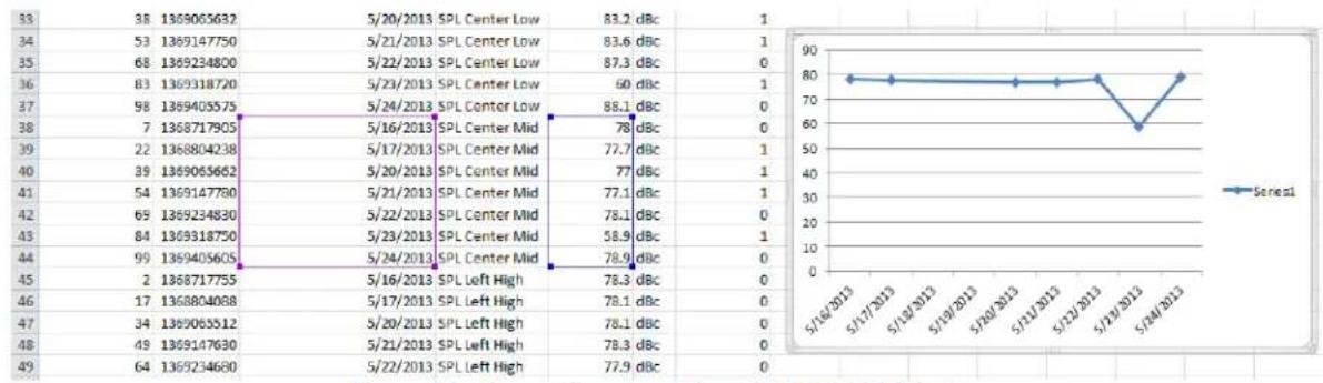
Sort the spreadsheet on column D (descripon) to gather like readings together. Graphing or analysis can then be easily accomplished. The image below shows the generaon of a plot of the SPL from the center channel mid-band measurements.
LSS-100P Installaon & Operaon Manual
line
| Date | SPL Center Low (dBc) | SPL Center Mid (dBc) | SPL Center Mid (dBc) | SPL Left High (dBc) | SPL Left High (dBc) | SPL Left High (dBc) | | :--- | :--- | :--- | :--- | :--- | :--- | :--- | | 5/16/2013 | 83.2 | 78.0 | 78.0 | 78.0 | 78.0 | 78.0 | | 5/17/2013 | 83.6 | 78.0 | 78.0 | 78.0 | 78.0 | 78.0 | | 5/18/2013 | 83.6 | 78.0 | 78.0 | 78.0 | 78.0 | 78.0 | | 5/19/2013 | 87.3 | 78.0 | 78.0 | 78.0 | 78.0 | 78.0 | | 5/20/2013 | 60.0 | 77.1 | 77.1 | 78.3 | 78.3 | 78.3 | | 5/21/2013 | 88.1 | 77.1 | 77.1 | 78.1 | 78.1 | 78.1 | | 5/22/2013 | 78.0 | 77.1 | 77.1 | 78.1 | 78.1 | 78.1 | | 5/23/2013 | 77.7 | 77.1 | 77.1 | 78.3 | 78.3 | 78.3 | | 5/24/2013 | 88.1 | 77.1 | 77.1 | 78.9 | 78.9 | 78.9 | | 5/25/2013 | 88.1 | 77.1 | 77.1 | 78.9 | 78.9 | 78.9 | | 5/26/2013 | 88.1 | 77.1 | 77.1 | 78.9 | 78.9 | 78.9 | | 5/27/2013 | 88.1 | 77.1 | 77.1 | 78.9 | 78.9 | 78.9 | | 5/28/2013 | 88.1 | 77.1 | 77.1 | 78.9 | 78.9 | 78.9 | | 5/29/2013 | 88.1 | 77.1 | 77.1 | 78.9 | 78.9 | 78.9 | | 5/30/2013 | 88.1 | 77.1 | 77.1 | 78.9 | 78.9 | 78.9 | | 5/31/2013 | 88.1 | 77.1 | 77.1 | 78.9 | 78.9 | 78.9 | | 5/32/2013 | 88.1 | 77.1 | 77.1 | 66.0 | 66.0 | 66.0 | | 5/33/2013 | - | - | - | - | - | - | | 5/34/2013 | - | - | - | - | - | - | The chart displays a line graph of Series1's performance over time from May to May-24, with data points labeled for each date and series.Figure 14 – Graph Generaon from LSS-100P CSV Data
Mulple Logs on One Page
It may be desirable to have a single web page that includes the logs from mulple LSS-100P units (for example, all the auditoriums in a parcular theater). This can be accomplished using HTML iframes (inline frames). Sample code to include mulple LSS-100P log pages is shown below. This code can be placed on the computer the browser is running on or on a local web server.
<!doctype html>
<html>
<head>
    <title>Obispo LSS-100 Summary</title>
</head>
<body>
    <hl align="center">Obispo LSS-100 Summary</title>
    <iframe seamless frameborder="0" src="http://192.168.6.55/log.cgi?n=20&GuiTz=-25200&GuiTzName=Pacific%20Standard%20Time&DST=1" width="100%" height="700"></iframe><br />
    <iframe seamless frameborder="0" src="http://192.168.6.110/log.cgi?n=20&GuiTz=-25200&GuiTzName=Pacific%20Standard%20Time&DST=1" width="100%" height="700"></iframe>
</body>
</html>
The iframe does a "client side include" of mulple web pages. The aributes of the iframe tag are described below.
The seamless and frameborder="0" aributes merge the fetched log pages into the resulting page with no frame borders so it appears to be one page.
The src aribute contains the URL of the log to be inserted at this point. It is simplest to connect to the LSS-100P home page, click log, then copy the resulting URL for use here with the changes listed below.
Delete the "rn=xx&" from the URL. rn holds the rst record number to be displayed. The next part of the URL ("n=100") indicates how many records will be shown. If rn is deleted, the LSS-100P shows the n most recent records. By deleng rn from the URL in the iframe, your page will always show the most recent log entries.
Change "n=100" to "n=20" or some other number indicang the number of log entries you want shown on this combined log page. If you do a daily log review, you may want to show three days worth of log entries to ensure data from weekends is reviewed.
LSS-100P Installaon & Operaon Manual
GuiTz can generally remain unchanged. It is the oset in seconds from UTC where the browser is located. Similarly, the GuiTzName can remain unchanged. You may need to change DST between 1 and 0 depending on whether daylight saving me is currently in eect. You could build two pages (one for DST and one for standard me) or include the javascript at the top of the LSS-100P home page that determines whether DST is in eect at the GUI.
The width aribute is set to 100% so the iframe consumes 100% of the width of the browser window. The height is specied in pixels. If this is too small, scroll bars will appear on the resulting web page for each of the iframes. Making it too large results in empty space on the page. Experiment with this unl you get the look you want for mulple logs on a single web page.
Mulple Auditorium Summary
Another method of presenng mulple auditoriums on a single web page is to build a list of links to the auditoriums. The LSS-100P automacally supplies a link to a log that includes the theater name and the screen number. If there is an out of limits log entry in the log record range specied, the log link appears in red. You don't have to look at logs from auditoriums where all is well. Sample HTML is shown below.
<!doctype html>
<html>
<head>
    <title>Obispo LSS-100 Summary</title>
</head>
<body>
    <h1 align="center">Obispo LSS-100 Summary</title>
<iframe seamless frameborder="0" src="http://192.168.6.55/loglink.cgi?n=20&GuiTz=-25200&GuiTzName=Pacific%20Standard%20Time&DST=1" width="100%" height="50"></iframe><br/>
<iframe seamless frameborder="0" src="http://192.168.6.110/loglink.cgi?n=20&GuiTz=-25200&GuiTzName=Pacific%20Standard%20Time&DST=1" width="100%" height="50"></iframe>
Most of the iframe aributes are similar to the previous example. As noted before, the lack of an rn in the src aribute tells the LSS-100P to evaluate the last n records for an out of limit condion. In the examples above, a parcular log link will be red if one of the last 20 records shows an out of limits condion.
The image below shows how the HTML above appears in our test system:
USL San Luis Obispo - Screen 1
USL San Luis Obispo - Screen 4
Figure 15 - LSS-100P Mulple Auditorium Links
Ethernet Device Discoverer Windows version
Ethernet Device Discoverer (hp://p.uslinc.com/?dir=p/Products/EthernetDeviceDiscoverer) discovers USL devices on a network. In addition, it shows the status of discovered LSS-100P
LSS-100P Installaon & Operaon Manual
devices. The LSS-100P status messages shows any out of tolerance measurements in the previous number of days where the number of days is set in the Web Display Conguraon Page (gure 5).
| IP Address | Host Name | MAC Address | Serial # | Location | Screen | Model | Status |
| 192.168.6.1D | LSS-100 | 00-23-FC-06-0C-F5 | 3317 | USL San Luis Obispo | 1 | LSS-100 | SPL Silence high. SPL Left Low low. SPL Left Mid low. SPL Left High low. SPL Right L |
| 192.168.7.64 | TH-1_LSS-100P | 00-23-FC-06-15-1F | 5465 | USL Tast Screen 1 | 1 | LSS-100 | SPL Center Low low. SPL Center Mid low. SPL Center High low. SPL LFE low. SPL Ls |
| 192.168.7.40 | TH1_JSD-60 | 00-23-FC-07-00-78 | 120 | ** Factory Default ** | 1 | JSD-60 | |
| 192.168.7.63 | TH1_CAPTIONS | 00-23-FC-02-25-3F | UltraStereo | 1 | IRC-28C | ||
| 192.168.6.57 | HH MONITOR | 00-23-FC-0B-00-7B | 123 | Obispo | 4 | CM-BE | |
| 192.168.7.231 | MP1-JSD-100 | 00-23-FC-05-12-FF | 004863 | USL San Luis Obispo | 1 | ||
| 192.168.7.232 | JSD-100_MP-2 | 00-23-FC-05-20-18 | 008216 | USL 3 Plex | 2 | ||
| 192.168.7.233 | JSD-100_MP-3 | 00-23-FC-05-21-8D | 08637 | USL 3 Plex | 3 |
Figure 16 - Windows version of Ethernet Device Discoverer showing LSS-100P status in red.
Ethernet Device Discoverer iOS version
An iOS version of Ethernet Device Discoverer is available at hps://itunes.apple.com/us/app/ethernet-discoverer/id1086192624?mt=8. This applicaon oers the same set of features as the Windows version but operates on iOS devices (iPhone, iPad, etc.). Figure 17 shows the opening of the iOS version of Ethernet Device Discoverer.
Ethernet Device TCP Based Operaons
The LSS-100P uses TCP port 10001. It can accept 5 simultaneous TCP connexons. Commands are lower case and terminated with a carriage return (0x0d). Parameters, if any, are separated by tab characters (0x09) or a pipe character (|). Responses are in ASCII and terminated with a carriage return. If mulple values are returned, they are separated with tab characters. In some cases, there may be a tab character aer the last response and before the carriage return. The command is not echoed by the LSS-100P.
LSS-100P commands can be tested using Tera Term, RealTerm (both listed below), or telnet on operang systems that include it (Windows XP, Linux, Mac OS). Since the LSS-100P does not echo commands or append line feed characters, Tera Term and similar programs should be set for local echo and CR+LF on receiving a carriage return. These opons are in the Setup – Terminal menu on Tera Term.
The LSS-100P commands and typical responses are shown in Figure 17. Note that many of these commands are commonly used in scripts (described previously), and the lss100.sys.script_run command can be used to start script execuon.
Figure 17 - Etherent Device Discoverer iOS version
| Command | Response | Descripon |
| Iss100.sys.auditorium | 1 | Returns the auditorium number entered on the conguraon page. |
| Iss100.sys.cct | 6255.250284 | Returns the correlated color temperature. |
| Iss100.sys.cdm2 | 405.151492 | Returns the luminance in candelas per square meter |
| Iss100.sys.comments | Conference Room | Returns the auditorium comments entered on the conguraon page. |
| Iss100.sys.l | 118.332596 | Returns the measured luminance in foot-Lamberts |
| Iss100.sys.spl | 83.239520 | Returns the measured sound pressure level in dBc |
| Iss100.sys.temperature | 29.2\t84. | Returns the internal temperature in degrees C and degrees F (separated by tab). |
| Iss100.sys.theater_name | USL San Luis Obispo | Returns the theater name entered on the conguraon page. |
| Iss100.sys.theater_number | 1 | Returns the theater number entered on the conguraon page. |
| Iss100.sys.ver | H\t130522\t120530 | Returns the circuit board version, the rmware version, and the bootloader versions, separated by tab. |
| Iss100.sys.xy | 0.314743\t0.353419 | Returns the chromacity as x tab y. |
| Iss100.sys.capture_spl|SPL Center Low|81.2|83.2 | 83.239520 | Instructs the LSS-100P to capture the current SPL to its log. The parameters are descripon, min, and max. Returns the current SPL in dBc. |
| Iss100.sys.capture_|Luminance|13|15 | 14.1234 | Instructs the LSS-100P to capture the luminance (measured in fL) to its log. The parameters are descripon, min, and max. |
| Iss100.sys.capture_cdm2|Luminance|47|49 | 48.4321 | Instructs the LSS-100P to capture the luminance (measured in cd/m2) to its log. The parameters are descripon, min, and max. |
| Iss100.sys.capture_cct|Color Temperature|6100|6300 | 6262 | Instructs the LSS-100P to capture the correlated color temperature in Kelvin to its log. The parameters are descripon, min, and max |
| Iss100.sys.capture_temperature_c|Temperature|20|40 | 25 | Instructs the LSS-100P to capture its internal temperature in Celsius to its log. The parameters are descripon, min, and max. |
| Iss100.sys.capture_temperature_f|Temperature|60|80 | 70 | Instructs the LSS-100P to capture its internal temperature in Fahrenheit to its log. The parameters are descripon, min, and max. |
| Iss100.sys.capture_x|Color|0.308|0.320 | 0.314 | Instructs the LSS-100P to capture the color coordinate x. The parameters are descripon, Xmin, Xmax. |
| Iss100.sys.capture_y|Color|0.345|0.357 | 0.351 | Instructs the LSS-100P to capture the color coordinate y. The parameters are descripon, Ymin, Ymax. |
| Iss100.sys.cp850_test_start|192.168.1.146 | Sends a command to a Dolby CP850 to output a test signal. The test signal is pink noise that rotates through all speakers. | |
| Iss100.sys.cp_850_test_stop | Stops the test signal generaon in the Dolby CP850 and returns it to normal operaon. | |
| Iss100.sys.log_post|hp://Iss.uslinc.com/post.phpIss.100.sys.log_post|http://user:pw@example.com:1234/path/filename | Posts logs in XML to the specied URL. The URL can be HTTP or HTTPS. The post can use either HTTP or HTTPS. The URL can include a username, password, and port number, if desired. Posts all log data since the last log post to this URL. If more than one post is included in a script, add a wait of 60 seconds between posts to allow me for the rst to complete. | |
| Iss100.sys.tcp_send_string|address|port|stringIss100.sys.tcp_send_string|192.168.1.123|10001|qli32.sys.test.speaker_test 15 1\r | Allows a user to have the LSS-100P relay a TCP string to another device. | |
| Iss100.sys.script_run|0 | Runs the specied script. If no script number is specied, runs script 0 (the rst one). | |
| Iss100.sys.script_wait|30 | Causes a script to wait the specied number of seconds before execung the next line. Waits between captures keeps the measurement capture synchronized with the test content. |
Figure 18 - LSS-100P TCP Commands
TCP\_Send Command Usage
The tcp_send command allows a user to have the LSS relay TCP strings to other devices by having the command embedded within a script. The usage of this command is shown below:
Iss100.sys.tcp_send_string|address|port|string
Example:
Iss100.sys.tcp_send_string|192.168.1.123|10001|qli32.sys.test.speaker_test 15 1\r
The example command tells a Lexicon QLi32 (located at 192.168.1.123, port 10001) to put pink noise on each speaker in sequence for 15 seconds (looping once). An LSS-100P script can capture the SPL of each of the speakers.
Allowed escape codes are:
\ = backslash
\t = tab
\n = newline
\r = carriage return
\a = alarm (bell)
\f = form feed
\v = vercal tab
\b = backspace
CP850 Control
The LSS-100P is capable of integraon with a Dolby® CP850 Cinema Processor to check individual speakers in a Dolby ATMOS® conguraon. To unlock access to TCP commands that control the Dolby© CP850 Cinema Processor contact USL for a license key.
The command below causes the LSS-100P to send a command to the CP850 at the specied address (192.168.1.146 in the example) to go into a test mode. In this mode, the CP850 sends pink noise to each speaker individually. By ming how much me is spent on each speaker, a custom test script can be written so the LSS-100P captures the SPL on each speaker.
Iss100.sys.cp850_test_start|192.168.1.146
The command below causes the LSS-100P to send a command to the CP850 stopping the test. The IP address specified in the last cp850_test_start is used.
Iss100.sys.cp_850_test_stop
Log Post XML Format
Sample XML data posted to a web server is shown below. Note that the web server must accept chunked data as denied in RFC 2616 secon 3.6.1. Note that DateTime is a Unix me stamp (seconds since January 1, 1970 UTC).
<?xml version="1.0" encoding="UTF-8"?>
<LssLogPost>
<Record>
<RecordNum>996</RecordNum>
<DateTime>1440661743</DateTime>
<Description>Posted to http://lss.hallikainen.org/post.php</Description>
<Value>3.39e+03</Value>
<Units></Units>
<Minimum>-9e+09</Minimum>
<Maximum>9e+09</Maximum>
<OutsideLimits>0</OutsideLimits>
<SerialNumber>0157</SerialNumber>
<OrgKey>palm</OrgKey>
<TheaterName>Palm Theatre</TheaterName>
<TheaterNumber>1</TheaterNumber>
<AuditoriumNumber>1</AuditoriumNumber>
<Comments>HW Rev F</Comments>
<Firmware>150721</Firmware>
<Hardware>F</Hardware>
<IpAddress>192.168.1.153</IpAddress>
</Record>
<Record>
<RecordNum>997</RecordNum>
<DateTime>1440661743</DateTime>
<Description>Log post response code</Description>
<Value>200</Value>
<Units></Units>
<Minimum>0</Minimum>
<Maximum>399</Maximum>
<OutsideLimits>0</OutsideLimits>
<SerialNumber>0157</SerialNumber>
<OrgKey>palm</OrgKey>
<TheaterName>Palm Theatre</TheaterName>
<TheaterNumber>1</TheaterNumber>
<AuditoriumNumber>1</AuditoriumNumber>
<Comments>HW Rev F</Comments>
<Firmware>150721</Firmware>
<Hardware>F</Hardware>
<IpData>192.168.1.153</IpAddress>
</Record>
<Record>
<RecordNum>998</RecordNum>
<DateTime>1440661834</DateTime>
<Description>SPL Silence</Description>
<Value>56.4</Value>
<Units>dBc</Units>
<Minimum>40</Minimum>
<Maximum>60</Maximum>
<OutsideLimits>0</OutsideLimits>
<SerialNumber>0157</SerialNumber>
<OrgKey>palm</OrgKey>
<TheaterName>Palm Theatre</TheaterName>
<TheaterNumber>1</TheaterNumber>
<AuditoriumNumber>1</AuditoriumNumber>
<Comments>HW Rev F</Comments>
<Firmware>150721</Firmware>
<Hardware>F</Hardware>
<Ipaddress>192.168.1.153</IpAddress>
</Record>
... (additional records)
</LssLogPost>
LSS-100P Installaon & Operaon Manual
The web server can parse the XML to a database for further analysis and reporting. A simple PHP script that appends each new LSS-100P XML report to a le and mails each report is shown below. This is a good starng point to verify that things are working.
<?php
 CovidData=file_get_contents("php://input"); // get post data into a string
file_put_contents("/tmp/PostTest.txt",$PostData,FILE_APPEND); // append post data to a
file
// Set up to mail data
$to='name@example.com';
$subject='LSS-100 Post Data';
$headers='From: LSS@example.com';
mail(to,subject, PostData,headers);
?>
LSS-DB
LSS-DB is a free database program designed for use with the LSS-100P. It consists of PHP scripts and javascript to capture XML posts from LSS-100P units and present the data to users. LSS-DB is designed for use by theater chains or theater service companies that operate a Network Operaons Center. LSS-DB separates data from LSS-100P units by OrgKey. Users are only allowed access to data with a corresponding OrgKey. A single service company can serve many dierent theater chains with one LSS-DB installaon. An online demo can be viewed at hp://lssdb.uslinc.com . LSS-DB can be downloaded from hp://p.uslinc.com/?dir=p/Products/LSS-DB .
Hidden Screens
The LSS-100P has a few hidden screens that are described below. One shows the conguraon data for the unit. The other two allow for calibraon (or mis-calibraon) of the unit.
View Conguraon Data
The LSS-100P conguraon is saved as text in a series of commands. These commands are sent through the same command interpreter as commands received over TCP or from a script. You can view this data at http://xxx.xxx.xxx.xxx/ConfigFlash.html (substung the IP address of the LSS-100P for the xxx).
Calibraon Screens
These screens are supplied to allow for eld calibraon of the LSS-100P. You should ONLY aempt this if you have accurate reference instrumentaon. Light calibraon is to be done with a projector having the same illuminaon source as will be used in operaon. If a xenon projector is to be used, the LSS-100P must be calibrated with a xenon source (ideally the same projector). Luminance and color MUST be measured with a spectrometer-based instrument, such as the USL PCA-100. Reference measurements should be made as close to the LSS-100P posion as possible. Do not aempt calibraon without the appropriate equipment.
Two calibraon screens are available:
- hp://xxx.xxx.xx.xx/protect/cal.html - Calibraon using cd/m ^2 .
- hp://xxx.xxx.xx.xx/protect/calf.html - Calibraon using fL.
These screens are similar. A poron of the cal.html screen is shown in Figure 19.
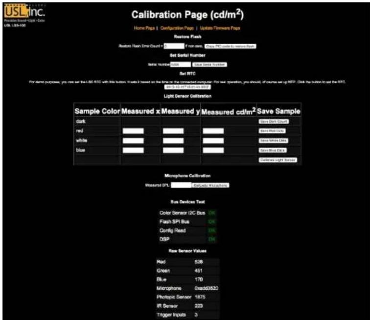
Figure 19 - LSS-100P Calibraon Screen
Besides calibraon, these screens includes factory conguraon features and debug informaon. The Copy PIC code to restore ash copies the currently loaded rmware to external ash as a backup. The number to the le of this buon is a count of how many bytes disagree. We recommend not clicking this buon in the eld. Keeping the factory rmware as a backup allows you to go back to it should something go wrong.
The Set Serial Number buon is not normally used in the eld. The MAC address of the LSS-100P is based on the serial number.
Use the procedure below to calibrate the light and IR poron of the LSS-100P:
- Present the LSS-100P with total darkness. This can be accomplished by pung a lens cap over the lens or by dowsing the projector and removing power from any IR panels in the auditorium. Once the LSS-100P is presented with total darkness, click the "Save Dark Count" buon. This sets a dark reference for both the luminance and IR sensors.
- Project a full-screen red test paern on the screen. Measure the color (x,y) and luminance with the spectrometer-based reference meter. While the test paern is sill on the screen, key these values in the "red" line of the calibraon form, then click "Save Red Data."
- Project a full-screen white test paern on the screen. Measure the color (x,y) and luminance with the spectrometer-based reference meter. While the test paern is sll on the screen, key these values in the "white" line of the calibraon form, then click "Save White Data."
- Project a full-screen blue test paern on the screen. Measure the color (x,y) and luminance with the spectrometer-based reference meter. While the test paern is sll on the screen, key these values in the "blue" line of the calibraon form, then click "Save Blue Data."
- Click the "Calibrate Light Sensor" buon.
LSS-100P Installaon & Operaon Manual
To calibrate the SPL meter, place a sound level calibrator, such as the Reed SC-05 over the LSS-100P microphone. Set the sound calibrator to 94dB. Key 94 into the Measured SPL eld, then click the Calibrate Microphone buon.
The remainder of the screen includes informaon to aid in the producon test of the LSS-100P. It can be ignored while doing eld calibraon of the LSS-100P.
Firmware Update
USL may oer rmware updates to add features to the LSS-100P. Firmware updates are delivered as a "hex" ie. To install the update, click on "Update Firmware Page" on the "Conguraon Page." The rmware update page is shown in Figure 20. Note that some rmware updates may result in a change in log format. For this reason, this page includes a "Clear Log" buon. This buon can also be used to clear the log for other reasons.

Figure 20 - LSS-100P rmware update page.
Follow these step-by-step instrucons to do a rmware update:
- Use the browse buon to select the hex le to be loaded into the LSS-100P.
- Press "Update Main Processor." The green LED on the LSS-100P will ash as the new rmware is installed. Aer the new code is uploaded to the LSS-100P, the browser will return a "Connecon Reset" message. This happens when the LSS-100P reboots with the new rmware.
If a rmware update is interrupted, it is possible for the LSS-100P to cease operang. To restore the factory rmware (allowing another aempt at the update), hold down the restore buon as power is applied to the LSS-100P. If the buon is held for about 1 second before and 1 second aer power is applied, the factory rmware will be reloaded and system conguraon will remain unchanged. The green LED ashes as the rmware is reloaded. Once the system is up and running, pressing the restore buon will restore the default IP address (169.254.1.6).
Restore Buon
The restore buon on the LSS-100P serves two purposes:
- If the restore buon is momentarily pressed while the LSS-100P is operang, the IP address is temporarily changed to its default IP address (169.254.1.6). It will stay at this IP address until the next power cycle.
- If the restore buon is held down 1 second before applying power until 1 second aer applying power, the factory rmware is reloaded. This can be used if a rmware update fails and leaves the system inoperable. The green LED will ash as the rmware is reloaded. No conguraon is changed in this process. The unit will remain at the same IP address.
Useful Soware
Several programs are available on the USL website that should prove useful with the LSS-100P.
| URL | Descripon |
| hp://p.uslinc.com/?dir=p/Products/EthernetDeviceDiscoverer | Ethernet Discoverer - Finds USL products on the network. Shows the MAC address, IP address, host name and other informaon. Clicking on a lisng opens the home web page of the device. Also reports logged out of tolerance informaon from the LSS-100P. Windows and iOS versions are available |
| hp://p.uslinc.com/MulProduct/Realterm_2.0.0.57_setup.zip | Real Term – A terminal program that can be used to send commands and see responses over RS232 or TCP. |
| hp://p.uslinc.com/MulProduct/ermp23.zip | Tera Term Pro – A terminal program that can be used to type commands to the LSS-100P and see responses. |
| hp://p.uslinc.com/?dir=p/Products/LSS-100P/Soware/TestContent | LST-100 Test DCP – Use this digital cinema content for the DCP-based operaon of the LSS-100P. This DCP is also available on a ash drive from USL. Order part number LST-100. |
| hp://p.uslinc.com/?dir=p/Products/LSS-DB | LSS-DB. A PHP/javascript applicaon that reports on thousands of LSS-100P units. |
Ethernet Device Discoverer
The USL Ethernet Device Discoverer is a helpful tool used to locate mulple LSS-100P's and other USL products on a network. For LSS-100P's it also shows summaries and warning messages if any readings fall out of tolerance within a set number of days. The amount of days to look for out of tolerance conditions can be set on the main Conguraon Page of each individual LSS-100P. Since it is able to display mulple devices on a single page it may be the easiest way to get an overview of an enre mulplex of LSS-100P's.

Figure 21 – Ethernet Device Discoverer Overview
LSS-100P Installaon & Operaon Manual
LSS Database Soware
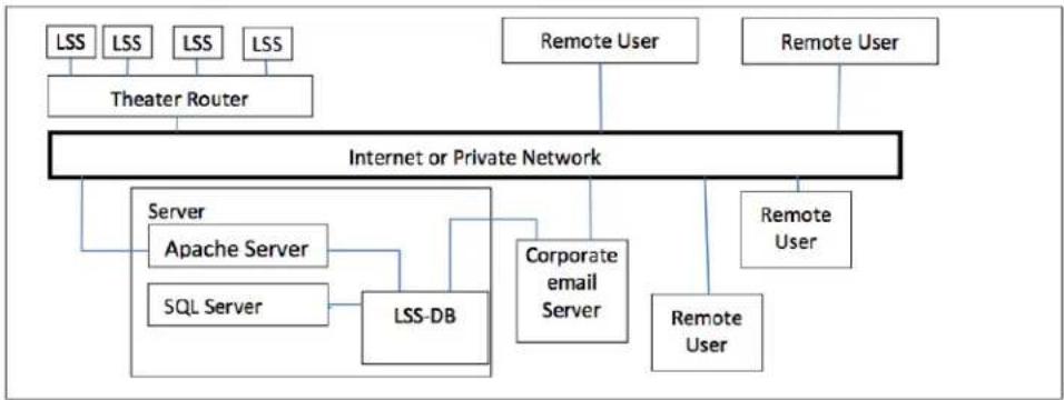
The LSS Database (LSS-DB) is designed to provide a collecon point for LSS-100P data transmiers and an observaon plaorm for reviewing the results of the collected data.
Remote LSS-100P devices that have been installed in theaters will post the results of each test to a URL (Uniform Resource Locator) where the LSS-DB collects the data. The LSS Database provides a mechanism to collect the LSS-100P data and store it in a database. This operaon is performed automatically and requires no intervenon by the end user.
Visit the following URL for download and more info: hp://p.uslinc.com/?dir=p/Products/LSS-DB
flowchart
graph TD
    A["LSS"] --> B["Theater Router"]
    C["LSS"] --> B
    D["LSS"] --> B
    E["LSS"] --> B
    F["Remote User"] --> G["Internet or Private Network"]
    H["Remote User"] --> G
    I["Server Apache Server"] --> J["LSS-DB"]
    K["SQL Server"] --> J
    L["Corporate email Server"] --> J
    M["Remote User"] --> N["Remote User"]
Figure 22 – LSS Database Overview
Appendix A – Red/Green Flash Script Start
LSS-100P installaon is simplified by using a red and green ash sequence to start script execuon. The ash sequence avoids the need to add a cue (send TCP string or provide contact closure) to start a script. The LSS-100P compares the output of the red and green sensors. When the green to red rao exceeds a threshold, the image is considered a binary 1. When the red to green rao exceeds a threshold, the image is considered a binary 0. A single ASCII character is sent using a sequence of red and green images. The character is sent at 0.5 bits per second (2 seconds per bit). The character consists of a start bit (0), 8 data bits with the least significant bit sent rst, then one stop bits (1). The most significant bit is 0. The script starts on the 0 to 1 transion between the most significant bit and the stop bit. Because of this, the script starts two seconds (one bit me) before the end of the clip. This two second dience needs to be taken into consideraon when wring scripts. Bits are sampled in the middle of the bit me (based on the 1 to 0 transion of the beginning of the start bit). The leer 'A' starts script 0 (the rst one).

line
| Time Segment | Event Description | Start/End Label | | ------------ | ------------------------- | --------------- | | 00 | Clip Start | Green | | 12 | Red | Start bit (red) | | 14 | Red | D0 | | 16 | Red | D1 | | 18 | Red | D2 | | 20 | Red | D3 | | 22 | Red | D4 | | 24 | Red | D5 | | 26 | Red | D6 | | 28 | Red | D7 | | 30 | Red | Stop bit (green)|Figure 23 - Red/Green ash ming diagram. This sequence represents the leer A (0x41) and will start script 0.
Appendix B – USB Power Interface and Contact Closure Script Start
Besides Power Over Ethernet, the LSS-100P can also be powered by a 5VDC power supply driving a mini-USB connector. A standard USB to min-USB cable can be used. As an alternate, USL can supply 10m (30) long cable, adapter board, and USB power supply to drive the LSS-100P. These can be used to power the LSS-100P and use contact closures to start scripts.
| Terminal | Wire Color | Wire Color |
| +5V | Red | Red |
| A | Blue | White |
| B | Yellow | Green |
| C | none | none |
| Ground | Black | Black |
Figure 24 - USB Adapter Pin-Out
natural_image
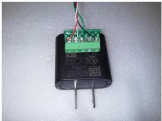
Close-up of a black electrical component with green connectors and wiring, no visible text or symbols.Figure 25 - USB Adapter Wiring
Note orientaon of adapter in USB power supply (terminals down).
1. If USB power or contact closure script triggering is being used, connect the supplied cable to the LSS-100P. Connect the other end of the cable to the USB adapter board. Refer to Figures 23 and 24 for wiring instrucons. If contact closure script triggering is being used with Power Over Ethernet, the USB cable can be routed directly to the GPIO connecons on the server. Refer to gure 4 for wire colors.
2. If contact closure script triggering is to be used, connect the contact closures from the digital cinema server to the USB adapter board as shown in Figure 25. Pulses should be about 500ms long.
| Pulse to ground | To Start Script |
| A | 0 |
| B | 1 |
| C | 2 |
Figure 26 - LSS-100P USB Adapter to Cinema Server GPIO Wiring
a) Dene a cue at the start of the Show Playlist to pulse (500ms) a contact closure between terminals A and ground on the USB adapter board. This contact closure or the Ethernet command causes the LSS-100P to start execung script 0 (the rst script).
Appendix C – Language Support
The primary language of the LSS-100P is English. User dened elds on the home page and in scripts may be in any language. The conguraon elds accept UTF-8 coding, allowing text of almost any language to be directly keyed in or pasted in.
Certain phases and words are “hard coded” into the LSS-100P in English. The web interface replaces these phrases and words using javascript when the browser renders the web page. The replacement is based on a table located in the /translate directory. For example, /translate/zh.txt hold the translation table for Chinese. Additional translation tables will be added in the future. The LSS-100P sends the appropriate translation table based on the rst language in the Accept-Language HTTP header.
Product Support
USL proudly stands behind its products. We are ready to answer quesons about the installaon or operaon of the LSS-100P. The manual, applicaon notes and other documents are available on our website. You may contact USL by:
File a support cket electronically at: www.uslinc.com/support
Please check the USL website for the latest soware packages and updates for the LSS-100P product. www.uslinc.com
USL is interested in your comments. Please feel free to contact us with any comments or suggestions.
Warranty
USL, INC. warrants that each product manufactured by it will be free from defects in material and workmanship under normal usage over a period of one (1) year aer its purchase new from and authorized dealer. Our obligaon under this warranty is limited to repairing or replacing any product or component which we are sased does not conform with the foregoing warrantee and which is returned to our factory freight paid, or serviced by one of our authorized contractors. The forgoing warranty is exclusive and in lieu of all other warranes, whether expressed or implied. Such warranty shall not apply to any product or component (A) repaired or altered by anyone other than USL, Inc. or an authorized service contractor; (B) tampered with or altered in any way or subjected to misuse, negligence or accident or (C) which has been improperly connected, installed or adjusted other than in accordance with USL, Inc.'s instrucon.
Manual Revision History
| Rev. | Descripon | Date |
| 1 | Original manual. | 111107 |
| 2 | Revisions for rmware and hardware changes. | 120112 |
| 3 | Revisions to accommodate hardware and rmware update. | 120217 |
| 4 | Editorial revisions | 120501 |
| 5 | Add documentaon on DCP-based operaon of the LSS-100P. | 130614 |
| 6 | Add documentaon on new hardware, scripng, etc. | 140604 |
| A | Added ToC, Support secon, improved formang. | 140619 |
| B | Added documentaon for new features. | 151015 |
| C | Added documentaon for new features. | 160318 |
- Installation and Operation Manual
- Table of Contents
- Table of Contents 2
- Introducon....3
- Features 4
- Firmware Version 6
- Installaon....6
- Data Analysis.... 15
- Ethernet Device TCP Based Operaons 19
- Hidden Screens.... 24
- Firmware Update 26
- Useful Soware.... 27
- Appendix A – Red/Green Flash Script Start 29
- Appendix B – USB Power Interface and Contact Closure Script Start.... 30
- Appendix C – Language Support.... 31
- Product Support 32
- Introducon
- Features
- Firmware Version
- Installaon
- NTP, IR, and Luminance Check
- Wring Command Scripts
- Script 0 - 2D:5.1
- Photo script start A
- Script starts, then two seconds of green, then ten second tone, then left low.
- Each noise sample is 19 seconds. Sample in middle.
- Script Test Run
- Data Analysis
- CSV Data Use
- Mulple Logs on One Page
- Mulple Auditorium Summary
- Ethernet Device Discoverer Windows version
- Ethernet Device Discoverer iOS version
- Ethernet Device TCP Based Operaons
- TCP\_Send Command Usage
- CP850 Control
- Log Post XML Format
- LSS-100P Installaon & Operaon Manual
- LSS-DB
- Hidden Screens
- View Conguraon Data
- Calibraon Screens
- Firmware Update
- Restore Buon
- Useful Soware
- Ethernet Device Discoverer
- LSS Database Soware
- Appendix A – Red/Green Flash Script Start
- Appendix B – USB Power Interface and Contact Closure Script Start
- Appendix C – Language Support
- Product Support
- Warranty
- Manual Revision History
Brand : USL
Model : LSS-100P
Category : Electronic sensor