CM-8E - Audio Amplifier USL - Free user manual and instructions
Find the device manual for free CM-8E USL in PDF.


| Product Type | Cinema Audio Monitor / Booth Monitor |
| Mounting | Standard 19-inch rack, 2U (3.5 in / 88.9 mm) |
| Power Supply | 100-240 VAC, 50/60 Hz, 300 mA maximum |
| Speaker | Internal speaker with front panel volume control |
| Headphone Output | Front panel 1/4-inch (6.35 mm) jack, mutes internal speaker |
| Audio Inputs | Main DB-25F (full range or low band), Crossover/Spare DB-25F (high band), HI/VI-N terminal block |
| Amplifier Outputs | DE-15F connectors (7) plus terminal blocks for screen, surround, and LFE channels |
| Amplifier Return Inputs | DE-15F Vmon pins and terminal block for amplifier output monitoring |
| Network Connectivity | 10/100 Mbps Ethernet for remote monitoring and configuration via web browser |
| Remote Monitoring | Web-based bar graph display and streaming audio (ADPCM or PCM) up to 2 minutes |
| Channel Selection | Front panel buttons for L, C, R, Ls, Rs, Lrs, Rrs, LFE, HI, VI-N, Spare; toggles processor or amplifier source |
| Biamp Support | Supports crossover before monitor (processor) or after monitor (amplifier) for L, C, R channels |
| LFE Configuration | Up to 4 LFE amplifiers; jumpers select LFE input or spare input for LFE3/LFE4 |
| Level Indication | Front panel VU LED bar graph and web bar graph with calibration |
| Compliance | CE, UL, cUL; FCC Part 15 Class A; EN 60950, EN 55022, EN 55024 |
| Operating Temperature | 0°C to 40°C (32°F to 104°F) |
| Humidity | 20% to 80% non-condensing |
| Safety Precautions | Use grounded outlet, correct power cable, avoid heat sources, ensure ventilation, no liquid cleaners |
| Warranty | One-year limited warranty against defects in material and workmanship |
| Accessories (optional) | Cables (IMF-6, VXC-2/6), PXC-3/4 adapters, DAT-100 digital audio generator, VP-1 vent panel |
Frequently Asked Questions - CM-8E USL
User questions about CM-8E USL
0 question about this device. Answer the ones you know or ask your own.
Ask a new question about this device
Download the instructions for your Audio Amplifier in PDF format for free! Find your manual CM-8E - USL and take your electronic device back in hand. On this page are published all the documents necessary for the use of your device. CM-8E by USL.
USER MANUAL CM-8E USL
1.0 Safety Noce....4
2.0 Regulatory Compliance 4
2.1 Declaraon of Conformity ....7
2.2 Equipment Class....8
2.3 Disposal and Recycling 8
3.0 System Version....9
4.0 System Overview....9
4.1 System Descripon....9
4.1.1 Front Panel User Interface 9
4.1.2 Network User Interface 9
4.1.3 Audio Inputs and Outputs 10
4.1.4 Biamped Systems 10
4.2 Block Diagrams ...... 10
5.0 Installaon ....13
5.1 Inial Power Up 13
5.2 System Hardware Mounng and Grounding 13
5.3 Crossover Opons....13
5.4 Rear Panel Connecons....15
5.4.1 Main Inputs 16
5.4.2 Crossover and Spare Inputs....17
5.4.3 DE-15F Amplifier Connectors 17
5.4.4 Terminal Block Amplifier Connectors....18
5.4.5 LFE Connecons and Conguraon 18
5.4.6 HI/VI-N Connecons....18
5.4.7 Ethernet Connector 18
6.0 System Conguraon....19
6.1 Congure LFE3/LFE4....19
6.2 Computer Network Connecon 19
6.3 Conguraon Screen....20
6.4 Network Conguraon....20
6.5 Audio Conguraon 21
6.6 Bar Graph Calibraon....22
6.7 Power Up Conguraon 23
6.8 Firmware Update 23
7.0 System Operaon....24
7.1 In-Booth Operaon 25
7.2 Browser Compatibility.... 26
7.3 Remote Monitoring....27
8.0 Product Support 29
Appendix A - Connector Pin Outs 30
Appendix B – System Restore and Power-Up Buons......36
Appendix C – CM-8E Accessories....36
CM-8E Manual History 37
1.0 Safety Noce
Safety Noces
Review the following safety precautions to avoid injury and prevent damage to this product. To avoid potential risk, use this product only as specified and only for the purpose described in the instrucon manual.
To Avoid Fire and Personal Injury:
- Use correct power cable. Use only the power cable provided. Ensure that the AC power outlet is located near the product and is easily accessible.
- Use a correctly grounded power source. The power supply earth ground is established through the ground conductor in the power cable. To avoid the potential of electric shock, the ground conductor must be correct.
- Observe source rangs. To avoid risk of re or electric shock, the power source must be 100 – 240 VAC, 50 – 60 Hz.
- Do not operate with suspected failures. If you suspect there is damage or malfuncon with this product, call the factory.
- Do not aempt repair. Only a trained factory service person is authorized to repair this product.
- Do not operate this product near heat sources. This product should not be located near heat sources such as radiators, heat registers, or stoves.
- Provide proper venlaon. The operang temperature range is between 0° C and 40° C. The humidity range is between 20% and 80%, non-condensing. The cooling method is convecon.
- Keep product surfaces clean and dry. Disconnect the power cable from the power source before cleaning. Do not use liquid cleaners or aerosol cleaners. Use a damp cloth for cleaning.
- Do not push objects into openings of this product. Never insert objects into the product through openings.
- Do not operate in wet or damp condions.
- Do not operate in an explosive atmosphere.
- Inspect the power cable and all cables prior to use. Conrm that the power cable and other interconnecng cables are free from damage.
2.0 Regulatory Compliance
EN 60950-1
The EN 60950-1 standard species the safety design requirements that reduce or eliminate the risk of personal injury to both the product user and service personnel. This product is designed and tested to meet the standards of the Internaonal Electrotechnical Commission (IEC)
European Norm EN 60950-1, IEC 60950-1 (the standard for informaon technology equipment including electrical business equipment).
2.1 Declaraon of Conformity
The CM-8E meets the intent of Direcve 89/336/EEC for Electromagnec Compatibility and Low Voltage Direcve 73/23/EEC for Product Safety. Compliance was demonstrated to the following speciaons as listed in the Ocial Journal of the European Communities:
EN 55022: 2006 Conducted and Radiated Emissions
- Conducted Emissions
- Radiated Emissions, Class A Limits
EN 55024: 1998 + A1: 2001 & A2: 2003 Immunity
• Electrostac Discharge Immunity
• RF Electromagnec Field Immunity
• Power Line Surge Immunity
- Conducted RF immunity
• Power Frequency Magnec Field Susceptibility
• Voltage Dips, Short Interrupons and Variaons
• EN 61000-3-3: 1995 +A1: 2001 & A2: 2005 Voltage Fluctuation and Flicker
FCC Part 15, Subpart B
This equipment has been tested and found to comply with the limits for a Class A digital device, pursuant to part 15 of the FCC Rules. These limits are designed to provide reasonable protecon against harmful interference when the equipment is operated in a commercial environment. This equipment generates, uses, and can radiate radio frequency energy and, if not installed and used in accordance with the instrucon manual, may cause harmful
interference to radio communicaons. Operaon of this equipment in a residential area is likely to cause harmful interference in which case the user will be required to correct the interference at user's own expense.
Cercaons
- Low Voltage Directive 73/23/EEC.
• EN 60950 Informaon Technology, Video, and similar Electronic Apparatus.
• IEC 60950 Safety Requirements. - CE, UL, cUL Safety and Overall Compliance.
• VDE Cered Power Cords. - Polluon: Not intended for environments where conducive pollutants may be present.
2.2 Equipment Class
Type A: Equipment that is intended for conneccon to the building power supply wiring via nonindustrial plugs and sockets or via appliance couplers, or both.
2.3 Disposal and Recycling
Wheelie-Bin Symbol

The Wheelie-Bin symbol is aached to this product in compliance with the EU Directive 2002/96/EC on Waste Electrical and Electronic Equipment (WEEE). Its purpose is to deter the improper disposal of this product and to promote reuse and recycling.
Proper Disposal
In conformance with the Direcve, at end of life this product should be either sent to an appropriate recycling facility for disassembly and recycling or returned to the supplier. Under no circumstances should this product be deposited in a landll for disposal.
Hazards of Noncompliance
Electrical and electronic products may contain chemicals, which can leach into the groundwater and cause health concerns through contaminated drinking water. Failure to dispose of this product in compliance with the WEEE Directive may result in penales as determined by local ordinance. Please contact your dealer or USL, Inc., with quesons regarding the proper disposal of this or any other USL product. USL, Inc. contact informaon: USL, Inc., 181 Bone Drive, San Luis Obispo, CA 93401-7397, USA. Phone: +1 805 549 0161 Fax: +1 805 549 0163 www.uslinc.com
3.0 System Version
The CM-8E is connuously being improved. New features are added through rmware. This manual describes the CM-8E versions available at this wring.
Firmware/soware versions for the systems described in this manual are listed in the table below:
| Component | Version |
| P32 | 140714 |
| Boot loader | 130806 |
| P24 | 130820 |
Check website www.uslinc.com for latest rmware.
4.0 System Overview
4.1 System Descripon
The CM-8E expands upon the standard booth monitor to allow network monitoring of cinema audio for quality control purposes. Network monitoring can meet the needs of a large network operaons center, or allow the manager to monitor auditorium audio from his or her oce. Of course, the CM-8E also serves the standard booth monitor purpose of allowing listening to various audio channels through the front panel speaker or headphones. Two user interfaces (the front panel and a web browser interface) are provided. The capabilities of each are listed below.
4.1.1 Front Panel User Interface
- Push buon selecon of audio channels to listen to, including HI and VI-N
- Listen to processor output or amplifier output
- Listen to individual bands of biamp crossover whether located in processor or amplifier
• LED level indicator of channels being listened to - Front panel volume control controls speaker and headphones
- Internal speaker
• Front panel headphone jack
4.1.2 Network User Interface
- Web browser based (no soware to install, use any operang system, monitor on desktop or tablet computer)
- Bar graph display of all processor output or amplifier output levels (individual biamp bands if crossover in processor or amplifier)
- Streaming audio monitoring of selected audio channels or bands from processor or amplifier
4.1.3 Audio Inputs and Outputs
The CM-8E simplifies the audio wiring of the booth. Audio from the cinema sound processor is delivered over one or two (for biamp crossover in processor) standard 25 pin D connectors (DB-25F). This eliminates the need for special cables or “break-out boards” for processors that have outputs only on DB-25 connectors (such as the USL JSD-60 or the Dolby® CP750).
The CM-8E has standard DE-15F (also known as HD-15 or VGA) connectors to drive the amplifiers. These standard connectors drive two channel amplifiers with balanced audio and provide a "V-mon" return signal so the amplifier output can be monitored.
The CM-8E also has pluggable terminal blocks for the interface to the amplifiers. These are used with amplifiers that do not have the DE-15 connectors. Terminals are provided for balanced audio to each channel of each amplifier. Terminals also accept a sample of the amplifier output so the output of the amplifier can be monitored.
4.1.4 Biamped Systems
The CM-8E supports the monitoring of systems with biamped screen channels (le, center, and right). If the crossover is located before the monitor (either within the sound processor or between the sound processor and the CM-8E), the CM-8E can monitor the total audio for each channel as well as the individual bands for the screen channels. If the crossover is located aer the monitor (within the amplifiers or aer the amplifiers), the CM-8E can monitor the full-range audio from the processor and monitor the individual bands from the amplifiers or crossover outputs. If the crossovers are located within the speakers, individual band samples are generally not available for monitoring. In this case, the CM-8E is congured for no crossover. When individual band monitoring is available, the front panel and web browser buons "scroll" through the bands. The sequence is o – both – low – high – o.
4.2 Block Diagrams
The following simplified block diagrams assist the user in understanding the signal ow within the CM-8E. The CM-8E provides a direct conncon from the sound processor to the ampliers, converng from DB-25 connectors to DE-15 and terminal block, with no intervening electronics. The CM-8E does not act the auditorium audio. Even if the CM-8E is turned o, the show goes on! The CM-8E bridges each processor balanced audio line with a dierenal
amplier with an input resistance of greater than 600k. These dierenal ampliers drive the audio switching matrix and the band/channel level detecon circuitry. Front panel and web browser buons select which channels and bands drive the front panel speaker, the front panel VU indicator, the web stream, and the web copy of the front panel VU indicator. All bands of all channels are measured connuously and sent to the web server for display on a remote web browser.
Band and channel audio from the audio switching matrix is sent to a digital signal processor (DSP) where the audio is digized. The digized audio level is measured to drive the front panel VU indicator and its web browser copy. The digital audio is then split to drive two compressors, one for the web stream and one for the front panel speaker. These compressors reduce the dynamic range of the audio to make it more suitable for the front panel speaker and the web stream. The speaker audio is also passed through an equalizer to compensate for the frequency response of the speaker itself. Finally, the speaker audio passes through a level control, then digital to analog conversion to drive the front panel speaker.
The output of the web stream compressor is sent to the web server. The web server streams the selected audio at 44.1k samples per second monaural as either IMA ADPCM (4 bits per sample for a total of 176kbps) or PCM (16 bits per sample for a total of 706kbps). The web server also sends the measured levels of each band and channel to the web browser to display them on a single bar graph.
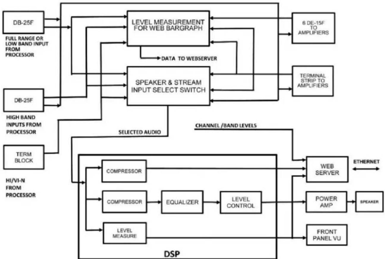
flowchart
graph TD
    A["DB-25F"] --> B["LEVEL MEASUREMENT FOR WEB BARGRAPH"]
    C["DB-25F"] --> D["SPEAKER & STREAM INPUT SELECT SWITCH"]
    E["TERM BLOCK"] --> F["COMPRESSOR"]
    G["HI/VI-N FROM PROCESSOR"] --> H["COMPRESSOR"]
    I["FULL RANGE OR LOW BAND INPUT FROM PROCESSOR"] --> B
    J["HIGH BAND INPUTS FROM PROCESSOR"] --> D
    K["SELECTED AUDIO"] --> F
    L["CHANNEL /BAND LEVELS"] --> M["WEB SERVER"]
    N["ETHERNET"] --> O["POWER AMP"]
    P["SPEAKER"] --> Q["FRONT PANEL VU"]
    R["6 DE-15F TO AMPLIFIERS"] --> B
    S["TERMINAL STRIP TO AMPLIFIERS"] --> D
    T["DATA TO WEBSERVER"] --> B
    U["LEVEL CONTROL"] --> F
    V["LEVEL MEASURE"] --> H
Figure 4.2a Audio Overview
5.0 Installaon
5.1 Inial Power Up
A quick power-up test of the CM-8E is suggested before mounng it in the equipment rack and wiring it up. This test can quickly detect shipping or other damage.
- Turn the AC power switch to the o posion.
- Using the supplied AC line cord or one appropriate for the installaon locaon (the power supply is a universal input supply 100-240 VAC, 50/60 Hz), connect the CM-8E to the AC line.
- Turn on the AC power switch. The red LED above the power switch should light. The other LEDs will ash as the unit goes through its power on self test. Aer the power on self-test, only the Power and Processor LEDs should remain lit.
- Press each of the channel buons several mes. LEDs above the buons should change. If a screen channel is set for biamp, the LED will stay lit through several buon presses since the sequence is o – all – low – high – o.
- Press the PROC/AMP buon and verify that the LEDs above the buon toggle with each buon push.
5.2 System Hardware Mounng and Grounding
The CM-8E is designed to mount in a standard 19 inch (482.6mm) rack and is two rack units high (3.5 inches, 88.9mm). The CM-8E should be mounted at a convenient height in the equipment rack considering ease of use of the front panel controls and the round of wiring between the CM-8E, the processor, and the amplifiers. The CM-8E includes a three-prong grounding plug and a three-wire power cord to accommodate a safe ground path from the chassis to the electrical system ground. Defeang this ground by removing the ground prong is not recommended.
5.3 Crossover Opons
The CM-8E is designed for use in auditoriums with a variety of crossover opons. These are illustrated in the gure below. In addition, the DE-15 connectors are wired on the assumpon that the le, center, and right channels will either be biamped or operated in bridge mode (with a “bridge ed load.”). If there is not a crossover before the CM-8E, the channel B outputs of the DE-15 connectors will have no audio. If there are crossovers in the amplifier, the CM-8E can be set to monitor the amplifier returns for each band.

flowchart
graph LR
    A["PROCESSOR WITH CROSSOVER DB-25"] -->|HIGH DB-25 LOW| B["CROSSOVER INPUT DB-25 CM-8E"]
    B -->|DE-15 B| C["AMPLIFIER"]
    C -->|OUTPUT B| D["HIGHSPEAKER"]
    B -->|MAIN INPUT DB-25| C
    B -->|DE-15 A| C
    C -->|DE-15 A| D
    style A fill:#f9f,stroke:#333
    style D fill:#bbf,stroke:#333
CM-8E can monitor individual bands from processor and amplifier on screen channels.
Crossover between Processor and Monitor

flowchart
graph LR
    A["PROCESSOR"] --> B["CROSSOVER"]
    B --> C["CROSSOVER INPUT DB-25"]
    C --> D["CM-8E MAIN INPUT DB-25"]
    D --> E["DE-15 B"]
    D --> F["DE-15 A"]
    E --> G["DE-15 B"]
    F --> H["DE-15 A"]
    G --> I["OUTPUT B"]
    H --> J["OUTPUT A"]
    I --> K["AMPLIFIER"]
    J --> K
    K --> L["HIGHSPEAKER"]
    K --> M["LOW"]
CM-8E can monitor individual bands from processor and amplifier on screen channels.
Crossover between Monitor and Amplifier

flowchart
graph LR
    A["PROCESSOR DB-25"] --> B["CM-8E MAIN INPUT DB-25"]
    B --> C["DE-15-A"]
    C --> D["CROSSOVER"]
    D --> E["HIGH AMPLIFIER"]
    E --> F["HIGH SPEAKER"]
    D -->|LOW| E
    D -->|HIGH| E
    E -->|LOW| G["High Speaker"]
CM-8E can monitor full range audio from processor. If individual amplifier returns are brought back to the CM-8E, it can monitor individual amplifier bands on screen channels.
Crossover in Amplier

flowchart
graph LR
    A["PROCESSOR\nDB-25"] --> B["CM-8E\nMAIN INPUT\nDB-25"]
    B --> C["DE-15-A\nAMPLIFIER WITH CROSSOVER"]
    C --> D["HIGH\nSPEAKER\nLOW"]
CM-8E can monitor full range audio from processor and individual bands from amplifier if the amplifier drives both Vmon pins on the DE-15 or individual amplifier outputs are brought back to terminal block.
Crossover between Amplifier and Speaker

flowchart
graph LR
    A["PROCESSOR DB-25"] --> B["CM-8E MAIN INPUT DB-25"]
    B --> C["DE-15-A"]
    C --> D["DE-15-A AMPLIFIER"]
    D --> E["CROSSOVER"]
    E --> F["HIGH"]
    E --> G["SPEAKER LOW"]
    E --> H["HIGH"]
Full range audio from processor can be monitored. Full range audio from amplifier can be monitored if amplifier returns are from amplifier. It may also be possible to get returns aer the crossover, in which case individual bands can be monitored.
Crossover within Speaker or Full Range Speaker

flowchart
graph LR
    A["PROCESSOR\nDB-25"] --> B["CM-8E\nMAIN INPUT\nDB-25"]
    B --> C["DE-15-A"]
    C --> D["DE-15-A\nAMPLIFIER"]
    D --> E["FULL RANGE\nSPEAKER\nOR\nINTERNAL\nCROSSOVER"]
Full range audio from processor and amplifier can be monitored.
The DE-15 connectors on the surround channels are wired for stereo full-range operaon. For example, one DE-15 connector has Ls on channel A and Rs on channel B.
5.4 Rear Panel Connecons
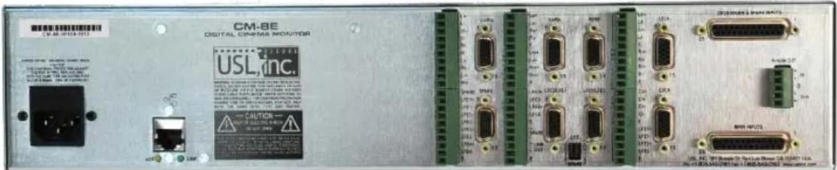
The rear panel connecons are shown in the drawing below.

- Power Inlet. 100 - 240VAC, 50/60 Hz, 300mA maximum.
- Ethernet. 10/100Mbps
- Amplifier Returns. Connect the positive side of amplifier outputs here if the DE-15 connectors are not used.
- Lrs/Rrs DE-15F. Drives the rear surround amplifier with le rear surround on channel A and right rear surround on channel B. Also provides amplifier returns (Vmon) for amplifier output monitoring.
- Spare DE-15F. The "spare" input (top DB-25 connector) drives channel A on this connector.
- Surround and LFE Terminal Block. These outputs can be used to drive amplifier inputs if the DE-15 connectors are not used. This terminal block also has "Line Out" terminals. This balanced output can drive an external power amplifier with the selected audio signals without compression or equalizaon. Such an amplifier could be used to drive a higher quality speaker than can praccally be placed within the CM-8E.
- Ls/Rs DE-15F. Drives the surround amplifier with le surround on channel A and right surround on channel B. Also provides amplifier returns (Vmon) for amplifier output monitoring.
- LFE3/LFE4 DE-15F. Drives the LFE3/LFE4 amplifier with LFE3 on channel A and LFE4 on channel B. Also provides amplifier returns (Vmon) for amplifier output monitoring.
- LFE3/LFE4 Source Select Jumpers. Put both jumpers in the up posion to drive these outputs with the LFE input from the processor. Put both jumpers in the down posion to drive these outputs with the spare input from the processor.
- LFE1/LFE2 DE-15F. Drives the LFE1/LFE2 amplifier with LFE1 on channel A and LFE2 on channel B. Also provides amplifier returns (Vmon) for amplifier output monitoring.
- Right Channel DE-15F. Drives the right channel amplifier. If there is a crossover before the CM-8E, channel A is driven with the low band, and channel B is driven with the
high band. If there is no crossover before the CM-8E, full range audio drives channel A and nothing drives channel B. The amplifier can have internal crossovers or operate in bridge mode. Also provides amplifier returns (Vmon) for amplifier output monitoring.
-
Screen and LFE Terminal Block. These outputs can be used to drive amplifier inputs if the DE-15 connectors are not used.
-
Le Channel DE-15F. Drives the le channel amplifier. If there is a crossover before the CM-8E, channel A is driven with the low band, and channel B is driven with the high band. If there is no crossover before the CM-8E, full range audio drives channel A and nothing drives channel B. The amplifier can have internal crossovers or operate in bridge mode. Also provides amplifier returns (Vmon) for amplifier output monitoring.
-
Center Channel DE-15F. Drives the center channel amplifier. If there is a crossover before the CM-8E, channel A is driven with the low band, and channel B is driven with the high band. If there is no crossover before the CM-8E, full range audio drives channel A and nothing drives channel B. The amplifier can have internal crossovers or operate in bridge mode. Also provides amplifier returns (Vmon) for amplifier output monitoring.
-
Crossover and Spare DB-25F. Receives high band audio for the le, center, and right channels from the processor or crossover. Also receives a spare audio channel.
-
Main DB-25F. If there is a crossover in front of the CM-8E, receives the low band audio for the le, center, and right channels from the processor or crossover. If there is no crossover in front of the CM-8E, receives full range audio for the le, center, and right channels from the processor. Also receives full range audio for the surround channels.
-
HI/VI-N Terminal Block. Receives HI and VI-N from the processor.
5.4.1 Main Inputs
The CM-8E main input is on a DB25F connector. This input receives “full range” audio from the sound processor if the sound processor does not have a crossover or there is no other crossover between the processor and the monitor. If the processor does include a biamp crossover for the screen channels or there is a crossover between the processor and the monitor, this input receives the low band of the screen channels. All other channels are full range. The L, C, and R inputs on this connector drive the “channel A” pins on the DE-15 connectors for the le, center, and right channels. The inputs are acve balanced (dierenal) inputs. They may be driven by balanced or unbalanced sources. When driven by an unbalanced source, the negave input should be connected to the low side of the source at the source equipment to minimize ground loop noise. The cable should be twisted pair with individual shields, even when driven by an unbalanced source. The DB25F connector uses the THX® pin out as specified in the table in Appendix A.
5.4.2 Crossover and Spare Inputs
This connector receives the high band audio for the screen channels (le, center, right) when there is a crossover before the CM-8E (either in the processor or between the processor and the CM-8E). These inputs drive the “channel B” pins on the DE-15 connectors for the le, center, and right channels. This connector also has an additional spare input that can drive an additional amplifier or additional LFE outputs and be monitored. The inputs are acve balanced (dierenal) inputs. They may be driven by balanced or unbalanced sources. When driven by an unbalanced source, the negave input should be connected to the low side of the source at the source equipment to minimize ground loop noise. The cable should be twisted pair with individual shields, even when driven by an unbalanced source. The DB25F connector uses the THX® pin out as specified in the table in Appendix A.
5.4.3 DE-15F Amplier Connectors
The CM-8E converts the DB-25 audio connector common on sound processors to the DE-15F connector (also called HD-15 or VGA) connector common on amplifiers. As described previously, the surround channels are “stereo” with two channels per connector. The screen channels have one channel per connector. If the screen channel is biamped before the CM-8E, channel A carries the low frequencies, and channel B carries the high frequencies. If the screen channel is not biamped before the CM-8E, channel A carries the full range audio, and channel B is silent.
The DE-15F connectors also provide an amplifier output return (Vmon or Voltage Monitor) to the CM-8E. Surround channels return the le on channel A and the right on channel B. The screen channels return the low band on channel A and the high band on channel B if the crossover is located before the CM-8E (in the processor or between the processor and the CM-8E) or if crossovers in the amplifier are enabled.
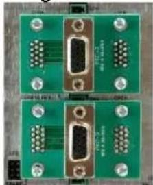
The CM-8E, by itself, always sends one screen channel through a two channel amplifier on the assumpon there is a crossover in the processor or amplifier. This is not always the case. USL oers the "PXC" series of adapters for those auditoriums that have crossovers in the speakers and need to carry two screen channels through one two-channel amplifier.
Figure 5.4.3a
natural_image
Close-up of two green printed circuit boards with various connectors and dials (no visible text or symbols)The PXC-3 combines le and right to drive one amplifier. A second PXC-3 combines center and LFE1 to drive a second amplifier.
Figure 5.4.3b

natural_image
Close-up of green circuit board components with gold connectors and terminal blocks (no visible text or symbols)The PXC-4 combines le and center to drive one amplifier. A second PXC-4 combines the right and LFE1 to drive a second amplifier.
5.4.4 Terminal Block Amplifier Connectors
The CM-8E provides pluggable terminal blocks to connect to the power amplifiers. These are commonly used with amplifiers that do not use the DE-15 connectors. Balanced outputs (+ and -) are provided for amplifier channels A and B. As with the DE-15 connectors, channel A carries the low band and channel B carries the high band in biamped installations. These are marked with I and h on the rear panel (for example, Lh+ for the positive side of the high band of the le channel). If there is not a crossover before the CM-8E, the full range signal will be available on the low band output of the CM-8E. In addition, terminals marked E (earth) are available for connecon to cable shields.
There are also pluggable terminal blocks to connect to amplifier outputs when DE-15 connectors are not used. One of these terminals connects to the positive terminal each amplifier output. The E terminal should be used to connect to a cable shield. Do NOT connect this to the negative output of the amplifier. Doing so could damage the amplifier or result in feedback. As with the terminals driving the amplifier, I is for the low band (channel A) and h is for the high band. If biamped amplifier outputs are not available, connect only to the 'I' terminals (the low band return).
5.4.5 LFE Connecons and Conguraon
The CM-8E can drive up to four LFE amplifiers. All four can be driven by a single LFE input from the processor, or LFE3 and LFE4 can be driven by the “spare” input (on the top DB25 connector on the rear panel). A 6 pin header with two jumpers is visible on the rear panel. Move both jumpers to the top posion (jumping top le to middle le and top right to middle right) to have the LFE input drive LFE3 and LFE4. Move these jumpers to the boom posion to have the spare input drive LFE3 and LFE4.
5.4.6 HI/VI-N Connecons
The CM-8E includes a pluggable terminal block for conneccon to the HI and VI-N outputs of the sound processor. A cable should be run from the CM-8E to these outputs on the sound processor. At the sound processor, these terminals also connect to the HI/VI-N transmier (such as a USL UPC-28). These conneccons allow the CM-8E to show the levels of the HI/VI-N signals and allow the signal to be listened to both locally and remotely.
5.4.7 Ethernet Connector
The Ethernet connector allows for remote monitoring of the audio passing through the CM-8E. A remote web browser can be used to select audio to listen to, see levels, and listen to the audio. In addition, the Ethernet connector is used when conguring the CM-8E.
6.0 System Conguraon
6.1 Congure LFE3/LFE4
LFE3 and LFE4 can be driven by the LFE output of the processor or a spare input to the CM-8E. If LFE3 and LFE4 are to be driven by the LFE output of the processor, put both LFE jumpers in the up posion (one jumper between the top le pin and the center le pin, the other between the top right pin and the center right pin). If LFE3 and LFE4 are to be driven by the spare audio input, put both jumpers in the down posion.
6.2 Computer Network Connecon
Connect an Ethernet cable between the CM-8E and a computer. In most cases, a “straight through” cable will work, but some older computers may require a “crossover cable.”
Open a web browser and type 169.254.1.10 (the default IP address of the CM-8E). You should see a page similar to that shown below. If the browser does not connect, try seng the IP address of your computer to be on the same subnet as the CM-8E. A good address to try is 169.254.1.123 with a subnet mask of 255.255.0.0. If the IP address has been changed away from its factory default, you can use the USL Ethernet Discoverer (available on the USL web site) to determine the IP address of the CM-8E. In addition, you can hold down the Le and Center buons during power up to restore the factory conguraon (including the default IP address). Note that these restored values are only held until the next power cycle unless they are saved.
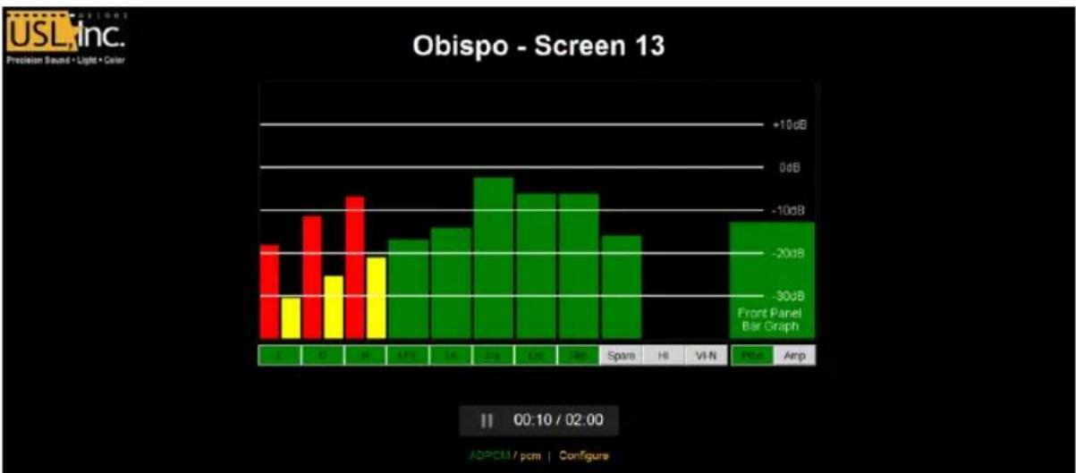
bar
Obispo - Screen 13 | Label | Value | |---|---| | C | -20dB | | G | -30dB | | H | -15dB | | EPC | -18dB | | TA | -22dB | | ES | -5dB | | LN | -7dB | | Ga | -8dB | | Spare | -18dB | | HI | 0dB | | VI-N | 0dB | | PEA | -12dB | | Amp | -14dB | IIS: 00:10 / 02:00 ADPCM / pcm | Configure6.3 Conguraon Screen
Click “Congure” at the boom of the page. The system will ask for a username and password. The username is “admin”, and the password is “ultra” (both lower case, no quotes). A page similar to the image below should appear.

The right side of the page shows informaon about the CM-8E including the serial number, circuit board revision, and rmware versions. There are two microcontrollers in the CM-8E, idened as P24 and P32. The P24 does audio level measurement for the web bar graphs. The P32 does everything else, including the web server. Each of these processors has a boot loader that allows for eld updates to the system. The version of the boot loader is also shown on this screen.
This page allows you to set auditorium speci data that is saved in the CM-8E. The theater name and screen number are shown on the web home page. Aer changing sengs, click the Save User Data buon to save the data.
6.4 Network Conguraon
Click the Network link on the third line of the page to get to the network conguraon screen. An image of that screen is shown below.
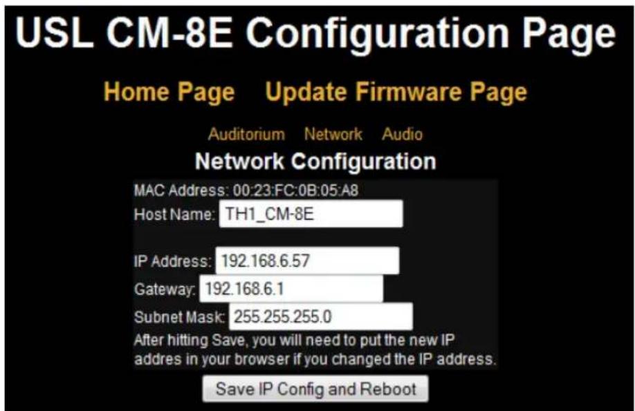
The Host Name is the Net BIOS host name. This can be used by Microso Windows computers to nd the CM-8E by name instead of IP address. This name is also shown in the USL Ethernet Discoverer (download from the USL web site). You may want to set a name that starts with the auditorium number and ends with the funcon. For example, “7 – Monitor” to indicate this is the booth monitor for screen 7. This will make the CM-8E easy to nd with Ethernet Discoverer.
Set the desired IP address, gateway, and subnet mask as appropriate for your theater IP addressing scheme. When all the informaon is complete, click the “Save IP Cong and Reboot” buon. Change the IP address in the browser address window to point to the new IP address. You should see the CM-8E appear at this new address (though you may need to change the IP address of your computer to be on the same subnet).
6.5 Audio Conguraon
Click the Audio link on the third line of the conguraon page. A screen similar to that below should appear.
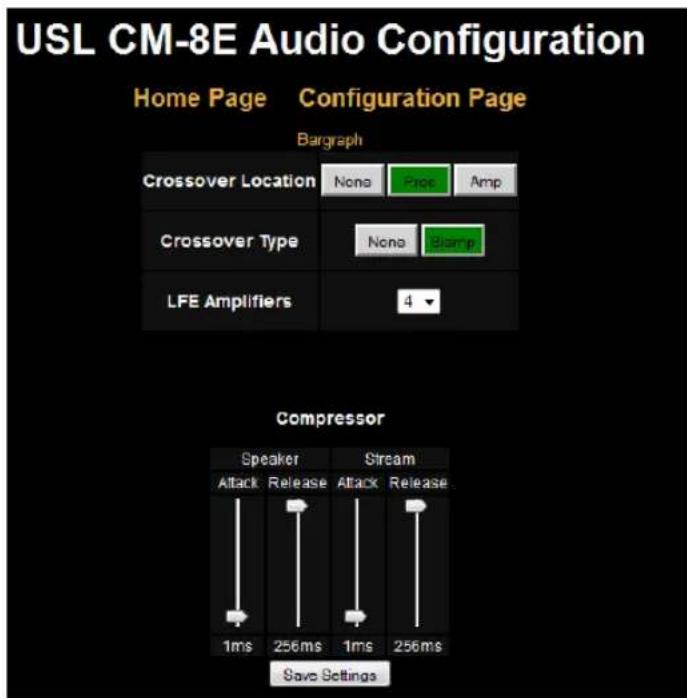
Select the locaon of the crossover, if any. If none is selected, the le, center, and right channels are assumed to be full-range. Pressing the front panel or browser buon will toggle these channels on and o on the monitor speaker and web stream. If the crossover locaon is set to Proc, the le, center, and right channels will step through an o- full range – low band – high band – o sequence for both the processor and ampliers. If the crossover locaon is set to Amp, the le, center, and right channels will toggle on and o if the processor is selected and through the sequence of off- full range – low band – high band – o when the amplifier is
selected. These sengs also aect the web bar graph display. If biamp audio is available on the processor or amplifier, the individual bands are shown on the bar graph. The crossover type can be biamp or none.
The CM-8E allows for monitoring of the individual LFE amplifier returns. Select the number of LFE amplifiers that are used in this auditorium. The front panel and web LFE buons allow sequencing through the individual LFE returns when the amplifier is selected (instead of the processor). In addition, the individual LFE returns are shown on the web bar graph when the amplifier is selected.
The CM-8E includes compressors for the speaker and web stream. These reduce the dynamic range to be suitable for these applicaons. The aack and release mes are adjustable, though the default values are normally suitable. A significantly slower aack me can cause clipping because the compressor would react too slowly to a loud sound. A shorter release me increase the average volume but can result in low frequency distoron as the compressor starts to follow low frequency waveforms.
Once the sengs on this page are complete, press the "Save Sengs" buon.
6.6 Bar Graph Calibraon
The CM-8E is calibrated to show 0dB with processor and amplifier return (through the DE-15 connector) levels of 300mVrms. This is correct for most installaons. However, you can adjust the bar graph calibraon for your parcular installaon. Click the “Bar graph” link at the top of the audio conguraon page to get a page similar to that shown below.

Play pink noise on a channel at reference level. Select only that channel using the front panel or web buons. A bar (or two for biamp) should appear above the buon corresponding to that channel. Click the mouse in the top box above the buon to increase the height of the bar and the boom box to decrease the height of the bar. As shown in the image above, when a
channel is biamped, two sets of boxes appear above each buon. The le one represents the low frequency band, and the right one indicates the high frequency band.
While one channel is being driven and is selected, click the increase or decrease words above the proc and amp buons. This will increase or decrease the height of the VU indicator on the front of the CM-8E and on the bar immediately above the proc and amp buons on the web page.
Note that the CM-8E uses an averaging circuit instead of an adding circuit to combine audio for the speaker, stream, and front panel VU. Consider what happens in an auditorium if a second channel is brought up with audio identical to the rst. Since there are now two amplifiers driving the auditorium with the same sound, the power has doubled, indicang an increase of 3dB. If a voltage adder (or summer) were used in the CM-8E, adding two identical voltages would result in a doubling of the voltage, or an increase of 6dB. As more channels are added, the sound in the auditorium increases by 3dB each me the number of channels is doubled, while the output of a summer would increase by 6dB each me the number of channels was doubled. This could easily result in an overload and clipping within the CM-8E.
With an averaging circuit, the voltages are averaged instead of summed. Averaging the voltage of two channels with identical audio results in the same audio level no maer how many identical channels are averaged. In this case, doubling the number of channels results in an increase of 0dB. If, however, we average a channel and silent channels, the resulting level drops. If there is audio on only one channel, but we select a second silent channel, the average drops to 12 the previous value (a drop of 6dB). In the auditorium, of course, adding additional silent channels results in a sound level change of 0dB. As such, the front panel VU indicator should be considered accurate only when a particular channel is being monitored and not when mulple channels are being listened to.
When all the bar graphs are calibrated, press the “Save Sengs” buon to save the bar graph calibraon.
6.7 Power Up Conguraon
The “Save Sengs” buons on the various conguraon screens save all the current sengs. The currently selected audio channels/bands for monitoring and the processor/amp selecon are also saved. Use the buons on the unit or the web page to select which channels are fed to the speaker and stream, then hit “Save Sengs.” These buon sengs will be restored the next me the unit is powered up.
6.8 Firmware Update
The CM-8E contains two microcontrollers, idened as P32 and P24. As improvements are made to the CM-8E, rmware updates will be available on the USL web site.

The update buons on the rmware update page (shown above) show the version number of the rmware in each of the microcontrollers. If USL has supplied you with a newer version (a .hex le), use the appropriate browse buon to locate the le, then click the appropriate update buon. During the update process, the front panel LEDs will ash. When the update is complete, the web page will me out. You should then be able to go back to this page (don't hit reload, as that will do the update again) or the conguraon page to see that the new versions have been installed.
The P32 includes the web server that is used during the update. During the update process, the memory in this processor is erased, then reloaded with the new rmware. If something goes wrong in this process, it is possible to end up with an inoperable unit. Should this happen, you can restore the factory rmware by holding down the Le and LFE buons when powering up the CM-8E. The front panel LEDs should ash as the factory rmware is restored.
7.0 System Operaon
The CM-8E allows the auditorium audio to be monitored both in the booth and remotely. A drawing of the front panel is below.

-
Input select buons. These determine which channels and bands are driving the front panel VU indicator, the front panel speaker, and the web stream. If the unit is congured for biamp operaon, the le, center, and right buons "scroll" through the full-range audio, the low band, and the high band before returning to o. Similarly, if there is more than one LFE amplifier, the combined LFE can be monitored along with each individual LFE amplifier. Finally, the Rs, Lrs, and Rrs buons select one source, the other, or both. For example, the rst buon press of Lrs selects the le rear surround audio. The next selects the HI audio. The next selects both. The next turns both o.
-
Volume control for the front panel speaker.
-
Processor/Amplier select switch. When processor is selected, the front panel speaker and the web stream play the processor audio output of the selected channels and bands. The VU indicates the relave level of the same audio. When amplifier is selected, these each play the audio from the amplifier outputs (Vmon). This buon also determines whether the processor or amplifier is driving the web bar graphs.
-
VU audio level indicator. Displays the approximate audio level of the selected channels and bands. See secon 6.6 for more details on the VU indicacn.
-
Headphone jack. Plug monaural or stereo headphones into this jack. The speaker is muted when the headphones are plugged in. The front panel volume control adjusts the headphone volume. Do not plug test equipment into this jack that may ground any of the headphone connecons (including the connector sleeve).
-
Speaker. The selected audio channels and bands are heard through this speaker.
-
Power switch and power indicator. The power must be on for the CM-8E to operate. However, even when the power is 0, audio from the processor is passed through to the amplifiers.
7.1 In-Booth Operaon
The CM-8E operates very much like a traditional booth monitor. Pressing a front panel buon selects one or more audio channels to be listened to. You can listen to the audio at both the output of the processor and the output of the amplifiers (using the Vmon return from the amplifiers). If the screen channels have crossovers, you can listen to the combined audio (both high and low bands), and the individual bands. When no crossovers are present, pressing a buon toggles that channel between on and o. When crossovers are present, pressing the buon cycles through an o- full range – low band – high band – o sequence. Similarly, if more than one LFE amplifier is present, the LFE amplifier outputs can be sequence through when the amplifiers are selected (instead of the processor). Finally, the buons used to select the right surround, le rear surround, and right rear surround can also be used to select the spare, HI, and VI-N inputs. The buon sequences through one input, then the other, then both, before returning to o. The LEDs above the buons indicate which audio channels are selected.
The CM-8E includes an internal speaker, volume control, and headphone jack. Adjust the volume control to the desired level on the speaker or headphones. Headphones with a 14 inch monaural or stereo plug can be plugged into the headphone jack. Do not plug test equipment or anything that may ground one of the headphone connecons (including the sleeve) into the headphone jack, as this could damage the power amplifier.
The front panel VU indicator provides an approximate indication of the sound level of the selected audio channels.
If an external power amplifier has been connected to the line out terminals of the CM-8E, the channel select buons determine which audio is heard out of this amplifier. The volume control has no eect on the line out signal.
7.2 Browser Compatibility
The CM-8E uses HTML5 features that are available in most modern web browsers. The CM-8E decodes ADPCM in javascript on most browsers so no plugin is required. Browsers that cannot decode ADPCM in javascript will generally be able to decode it with a plugin (such as QuickTime or VLC). The table below shows browsers that have been tested and shown to work with the CM-8E.
| OS | Browser | Audio Streaming |
| Android | Chrome 35.0 | ADPCM supported. |
| Android | Dolphin 11.0.1 | PCM supported |
| Android | Firefox 30.0 | ADPCM and PCM supported. |
| Fedora 19 | Arora 0.11.0 | PCM supported. |
| Fedora 19 | Firefox 30.0 | ADPCM and PCM supported. |
| Fedora 19 | Midori 0.5.5 | PCM supported |
| Fedora 19 | Rekonq 2.4.2 | PCM supported |
| Fedora 19 | SeaMonkey 2.26 | ADPCM and PCM supported. |
| Fedora 19 | Web 3.8.2 | PCM supported. |
| iOS | Chrome 35.0 | ADPCM supported |
| iOS | Safari | ADPCM supported |
| OSX | Chrome 35.0 | ADPCM supported |
| OSX | Safari 6.1.4 | ADPCM and PCM supported |
| Windows | IE 11 | ADPCM supported with QuickTime plugin. |
| Windows | Firefox 31.0 | ADPCM and PCM supported. |
| Windows | Chrome 35.0 | ADPCM and PCM supported. |
| Windows | Opera 22.0 | ADPCM supported. |
7.3 Remote Monitoring
The CM-8E supports connuous level monitoring of all audio channels and short term (two minutes) listening to a selected combinaon of audio channels and bands. Remote operaon of the CM-8E is done with a standard web browser.
Use Ethernet Discoverer (available on the USL web site) to nd the CM-8E on the network, or type the IP address of the CM-8E in the address eld of a web browser. A screen similar to the image below should appear.

bar
Obispo - Screen 13 | Category | Value (dB) | |---|---| | L | -20 | | C | -30 | | R | -25 | | LPE | -15 | | G | -10 | | Pd | -5 | | Car | -5 | | Be | -5 | | Spare | -15 | | Hi | 0 | | V/N | 0 | | Amp | -10 | I Am: Front Panel Bar Graph ISS: PCM / pcm | ConfigureIn this installaon, the biamp crossover is in the processor (a USL JSD-60). The green buons indicate that we are listening to the combined audio of a 7.1 auditorium from the processor (the Amp buon is not green). The channel select buons are green when we are listening to a full range signal, red when we are listening to the low band, and yellow when we are listening to the high band. The red bar shows the low band level for a channel. The yellow bar shows the high band level. A green bar shows the level of a full-range channel. The green bar on the far right shows the level indicated by the front panel VU indicator on the CM-8E.
The internal ADPCM player is visible near the boom of the screen. Press the arrow buon to start playout for two minutes. Press the pause buon to pause the playout.
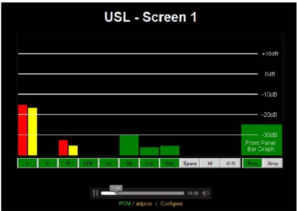
The green ADPCM at the boom of the page indicates that the ADPCM stream is being played. A PCM stream (which takes more bandwidth, but is higher quality and supported by more browsers) is available by clicking “pcm” at the boom of the screen. A screen with PCM audio playing appears below.
bar
USL - Screen 1 | Component | Current (dB) | |---|---| | L | -15 | | C | -18 | | R | -20 | | LFE | 0 | | La | 0 | | Ra | -30 | | Lre | -40 | | Rie | -45 | | Sparo | 0 | | Hi | 0 | | Vi-N | 0 | | Proc | -30 | | Amp | 0 |The PCM page uses a standard HTML5 audio tag, so no browser plugin is required. Reload the page to play the stream for an additional two minutes.
8.0 Product Support
One-Year Limited Warranty
USL, Inc. warrants that each product manufactured by it will be free from defects in material and workmanship under normal usage for a period of one (1) year aer its purchase new from an authorized dealer. Our obligaon under this warranty is limited to repairing or replacing any product or component which we are sased does not conform to the foregoing warranty and which is returned to our factory, freight paid, or serviced by one of our authorized contractors. The foregoing warranty is exclusive and in lieu of all other warranes, whether expressed or implied. Such warranty shall not apply to any product or component (A) repaired or altered by anyone other than USL, Inc. or an authorized service contractor; (B) tampered with or altered in any way or subjected to misuse, negligence or accident or (C) which has been improperly connected installed or adjusted other than in accordance with USL, Inc.'s instrucon.
USL proudly stands behind its products. We are ready to answer quesons about the installaon or operaon of the CM-8E. Applicaon notes, manuals, and other documents are available on our website. You may contact us by:
• Phone: +1 805 549 0161
• E-mail: support@uslinc.com
- You may le a support cket at: www.uslinc.com/support
USL Inc. is interested in your comments. Please feel free to contact us with any comments or suggestsons.
Appendix A – Connector Pin Outs
Connector Pin Outs
For convenience, all connector pin outs are located in this appendix.
Main Inputs
The main inputs are on a DB-25F on the rear panel. These are full range on all channels if there is no crossover in front of the CM-8E. They are the low band of the screen channels if there is a crossover in front of the CM-8E (typically in the processor)
Main Inputs, Full Range and Crossover
| Audio Channel | DB-25F Main Input Pins (+, -, shield) |
| Le | 2, 14, 1 |
| Center | 5, 17, 4 |
| Right | 8, 20, 7 |
| LFE | 25, 12, 13 |
| Ls | 23, 10, 22 |
| Rs | 24, 11, 9 |
| Lrs | 16, 3, 15 |
| Rrs | 19, 6, 18 |
Signals Listed By Connector Pins
| DB-25F Pin | Signal Name | Channel Name |
| 1 | GND | |
| 2 | L+ | Le+ |
| 3 | Lrs- | Le Rear Surround- |
| 4 | GND | |
| 5 | C+ | Center+ |
| 6 | Rrs- | Right Rear Surround- |
| 7 | GND | |
| 8 | R+ | Right+ |
| 9 | GND | |
| 10 | Ls- | Le Surround- |
| 11 | Rs- | Right Surround- |
| 12 | LFE- | Low Frequency Eects- |
| 13 | GND | |
| 14 | L- | Le- |
| 15 | GND | |
| 16 | Lrs+ | Le Rear Surround+ |
| 17 | C- | Center- |
| 18 | GND | |
| 19 | Rrs+ | Right Rear Surround+ |
| 20 | R- | Right- |
| 21 | ||
| 22 | GND | |
| 23 | Ls+ | Le Surround+ |
| 24 | Rs+ | Right Surround+ |
| 25 | LFE+ | Low Frequency Eects+ |
Crossover and Spare Inputs
When there is a crossover before the CM-8E, this connector carries the high band audio for the screen channels. In addition, this connector has a “spare” audio input.
Signals Listed By Channels
| Audio Channel | DB-25F CrossoverInput Pins (+, -, shield) |
| Le High | 2, 14, 1 |
| Center High | 5, 17, 4 |
| Right High | 8, 20, 7 |
| Spare | 25, 12, 13 |
Signals Listed By Connector Pins
| DB25F Pin Out | Signal Name | Channel Name |
| 1 | GND | |
| 2 | Lh+ | Le High+ |
| 3 | ||
| 4 | GND | |
| 5 | Ch+ | Center High+ |
| 6 | ||
| 7 | GND | |
| 8 | Rh+ | Right High+ |
| 9 | GND | |
| 10 | ||
| 11 | ||
| 12 | Spare- | Spare- |
| 13 | GND | |
| 14 | Lh- | Le High- |
| 15 | GND | |
| 16 | ||
| 17 | Ch- | Center High- |
| 18 | GND | |
| 19 | ||
| 20 | Rh- | Right High- |
| 21 | ||
| 22 | GND | |
| 23 | ||
| 24 | ||
| 25 | Spare+ | Spare+ |
HI/VI-N Inputs
The CM-8E has balanced HI and VI-N inputs that can monitor the audio from the processor to the HI/VI-N transmier (such as the USL UPC-28).
Signals Listed By Channels
| Audio Channel | HI/VI-N Phoenix Connector Pins (+, -, shield) |
| HI | 1, 2, 3 |
| VI-N | 5, 4, 3 |
Signals Listed By Connector Pins
| Phoenix Pin | Signal Name | Channel Name |
| 1 | HI+ | Hearing Impaired+ |
| 2 | HI- | Hearing Impaired - |
| 3 | GND | |
| 4 | VI-N- | Visually Impaired – Narrative- |
| 5 | VI-N+ | Visually Impaired – Narrative+ |
DE-15F Amplifier Outputs
The CM-8E has several DE-15F connectors to drive power amplifiers. On screen channels, one two channel amplifier per screen channel is used. Channel A carries the low band audio, and channel B carries the high band audio. If the crossover is before the CM-8E (typically in the processor), the channel A and B amplifier inputs carry the low and high band signals and the amplifier returns also carry the low and high band signals. If the crossover is in the amplifier, the amplifier channel A input is driven with full-range audio. The channel B input is not used. The amplifier returns low band audio to the CM-8E on the channel A return and high band audio on the channel B return. If the screen channels operate without a crossover (or with a crossover within the speaker), only the channel A input and return are used. The amplifier is typically placed in bridging mode so both channels drive one speaker. On the surround channels, the le surround (side or rear) is on channel A, and the right surround is on channel B.
DE-15F Signals by Pin
| Pin | Signal |
| 1 | Channel A – input |
| 2 | Standbyn – Pulled low to put amplifier in standby |
| 3 | Channel A Vmon (output voltage monitor) |
| 4 | Channel A Imon (output current monitor – not used on CM-8E) |
| 5 | No Connect |
| 6 | Chassis Ground (shield) |
| 7 | Channel A +input |
| 8 | Channel B +input |
| 9 | +15V from amplifier (not used by CM-8E) |
| 10 | Signal Ground (reference for Vmon and Imon) |
| 11 | Channel B –input |
| 12 | No Connect |
| 13 | Channel B Vmon (output voltage monitor) |
| 14 | Channel B Imon (output current monitor, not used by CM-8E) |
| 15 | No Connect |
Terminal Block Amplifier Outputs
The CM-8E has two terminal blocks providing outputs to the amplifiers plus a line output of the selected audio channels. The function of these terminals is shown on the rear panel and in the tables below. The amplifier output terminals duplicate the functionality of the DE-15F connectors. These terminals are normally used only if the amplifiers do not have DE-15 input connectors.
Screen Channel Terminal Block
| Terminal Number | Signal |
| 1 | Le High + |
| 2 | Le High - |
| 3 | Le Low + |
| 4 | Le Low - |
| 5 | Earth (chassis ground, cable shield) |
| 6 | Right High + |
| 7 | Right High - |
| 8 | Right Low + |
| 9 | Right Low - |
| 10 | Earth (chassis ground, cable shield) |
| 11 | Center High + |
| 12 | Center High - |
| 13 | Center Low + |
| 14 | Center Low - |
| 15 | Earth (chassis ground, cable shield) |
| 16 | LFE1+ |
| 17 | LFE1- |
| 18 | LFE2+ |
| 19 | LFE2- |
| 20 | Earth (chassis ground, cable shield) |
Surround Channel Terminal Block
| Terminal Number | Signal |
| 1 | Le Surround + |
| 2 | Le Surround - |
| 3 | Right Surround + |
| 4 | Right Surround - |
| 5 | Earth (chassis ground, cable shield) |
| 6 | Le Rear Surround + |
| 7 | Le Rear Surround - |
| 8 | Right Rear Surround + |
| 9 | Right Rear Surround - |
| 10 | Earth (chassis ground, cable shield) |
| 11 | LFE3+ |
| 12 | LFE3- |
| 13 | LFE4+ |
| 14 | LFE4- |
| 15 | Earth (chassis ground, cable shield) |
| 16 | Spare + |
| 17 | Spare - |
| 18 | Line Out + |
| 19 | Line Out - |
| 20 | Earth (Chassis ground, cable shield) |
Amplier Return Terminal Block
| Terminal Number | Signal |
| 1 | Le High + |
| 2 | Le Low + |
| 3 | Center High + |
| 4 | Center Low + |
| 5 | Right High + |
| 6 | Right Low + |
| 7 | Le Surround + |
| 8 | Right Surround + |
| 9 | Le Rear Surround + |
| 10 | Right Rear Surround + |
| 11 | Spare |
| 12 | LFE1 + (LFE ampliers have two returns since they normally operate in bridge mode) |
| 13 | LFE1 - |
| 14 | LFE2 + |
| 15 | LFE2 - |
| 16 | LFE3 + |
| 17 | LFE3 - |
| 18 | LFE4 + |
| 19 | LFE4 - |
| 20 | Earth (chassis ground, cable shield) |
Appendix B – System Restore and Power-Up Buons
The CM-8E has two methods of recovering from an unlikely failure. These are detailed below.
Restore Factory Firmware
If a rmware update of the main (P32) processor is interrupted, it is possible to leave the system inoperable. To restore the factory installed rmware, turn o the CM-8E, and then hold down the Le and LFE buons while turning the power back on. The front panel LEDs will ash as the factory rmware is restored. The CM-8E will then restart with the factory rmware.
Restore Default Conguraon
Hold down the Le and Center buons while powering up the CM-8E to restore the factory default conguraon. This causes the CM-8E to skip reading of the user denied conguraon. The factory conguraon is not saved to ash by this operaon. If you wish to save the factory conguraon to ash, hit the save sengs buon on any of the conguraon pages (each of these save all the current conguraon).
Appendix C – CM-8E Accessories
Cables
USL can supply the cables listed in the table below to simplify your CM-8E installaon.
| USL Part Number | Descripon |
| IMF-6 | DB-25M to DB-25F, 6 feet (914mm). Connect processor to CM-8E. Two required for biamp crossover in processor |
| VXC-2 | DE-15M to DE-15M, 2 feet (610mm). Connect CM-8E output to amplifier input. |
| VXC-6 | DE-15M to DE-15M, 6 feet (1.8m). Connect CM-8E output to amplifier input. |
DAT-100
DAT-100 Digital Audio Generator generates tone, voice, and pink noise signals on 16 AES/EBU channels. The DAT-100 can be used to verify the correct round and operaon of audio through the processor, monitor, and amplifiers.
VP-1
Vent panel to II the space and provide venlaon above and below the CM-8E.
PXC-3 Adapter
The PXC-3 combines le and right to drive one amplifier. A second PXC-3 combines center and LFE-1 to drive a second amplifier. See secon 5.4.3 for details.
PXC-4 Adapter
The PXC-4 combines le and center to drive one amplifier. A second PXC-4 combines right and LFE-1 to drive a second amplifier. See secon 5.4.3 for details.
CM-8E Manual History
| Version | Descripon | Date Code |
| 0.1 | Original | 131007 |
| 0.2 | Revise text and charts | 131008 |
| 0.3 | Update format and edits | 131009 |
| 0.4 | Revised text and format | 131011 |
| 0.5 | Format | 131015 |
| 0.6 | Update pictures and edits | 131017 |
| 0.7 | Update format and styles | 131022 |
| 0.8 | Update layout | 131106 |
| 0.9 | Revised text and layout | 131113 |
| 1.0 | Updated layout | 131114 |
| 1.1 | Added PXC, minor correcons | 131115 |
| 1.2 | Revised for new ADPCM streaming | 140715 |
| 1.3 | Added power up conguraon. | 140716 |
| 1.4 | Formang Standardized | 140724 |

- System Operaon....24
- Product Support 29
- Safety Noce
- Safety Noces
- To Avoid Fire and Personal Injury:
- Regulatory Compliance
- EN 60950-1
- Declaraon of Conformity
- EN 55022: 2006 Conducted and Radiated Emissions
- EN 55024: 1998 + A1: 2001 & A2: 2003 Immunity
- FCC Part 15, Subpart B
- Cercaons
- Equipment Class
- Disposal and Recycling
- Wheelie-Bin Symbol
- Proper Disposal
- Hazards of Noncompliance
- System Version
- System Overview
- System Descripon
- Front Panel User Interface
- Network User Interface
- Audio Inputs and Outputs
- Biamped Systems
- Block Diagrams
- Installaon
- Inial Power Up
- System Hardware Mounng and Grounding
- Crossover Opons
- Rear Panel Connecons
- Main Inputs
- Crossover and Spare Inputs
- DE-15F Amplier Connectors
- Terminal Block Amplifier Connectors
- LFE Connecons and Conguraon
- HI/VI-N Connecons
- Ethernet Connector
- System Conguraon
- Congure LFE3/LFE4
- Computer Network Connecon
- Conguraon Screen
- Network Conguraon
- Audio Conguraon
- Bar Graph Calibraon
- Power Up Conguraon
- Firmware Update
- System Operaon
- In-Booth Operaon
- Browser Compatibility
- Remote Monitoring
- Product Support
- One-Year Limited Warranty
- Appendix A – Connector Pin Outs
- Connector Pin Outs
- Main Inputs
- Crossover and Spare Inputs
- HI/VI-N Inputs
- DE-15F Amplifier Outputs
- Terminal Block Amplifier Outputs
- Appendix B – System Restore and Power-Up Buons
- Restore Factory Firmware
- Restore Default Conguraon
- Appendix C – CM-8E Accessories
- Cables
- DAT-100
- VP-1
- PXC-3 Adapter
- PXC-4 Adapter
Brand : USL
Model : CM-8E
Category : Audio Amplifier