JSD-80 - Processeur audio cinéma USL - Free user manual and instructions
Find the device manual for free JSD-80 USL in PDF.


| Product Type | Food Processor |
| Brand | USL |
| Model | JSD-80 |
| Dimensions (W x D x H) | 12.6 x 10.2 x 8.7 in (320 x 260 x 220 mm) |
| Weight | 5.5 lbs (2.5 kg) |
| Power Supply | AC 120V, 60Hz, 400W |
| Color | White and stainless steel |
| Bowl Capacity | 4 cups (1 liter) |
| Main Functions | Chopping, slicing, shredding, mixing, blending |
| Material | BPA-free plastic bowl, stainless steel blades |
| Noise Level | Less than 80 dB |
| Cord Length | 3 ft (0.9 m) |
| Safety Features | Overload protection, non-slip feet, safety lock lid |
| Cleaning and Maintenance | Removable parts are dishwasher safe; wipe motor base with a damp cloth |
| Included Accessories | S-blade, shredding disc, slicing disc, spatula |
| Spare Parts and Repairability | Replacement blades and bowls available; user-replaceable parts |
| Warranty | 1 year limited |
| Manual Languages | English (39 pages PDF) |
Frequently Asked Questions - JSD-80 USL
User questions about JSD-80 USL
0 question about this device. Answer the ones you know or ask your own.
Ask a new question about this device
Download the instructions for your Processeur audio cinéma in PDF format for free! Find your manual JSD-80 - USL and take your electronic device back in hand. On this page are published all the documents necessary for the use of your device. JSD-80 by USL.
USER MANUAL JSD-80 USL
Cinema Sound Processor
1. Introduction ...... 3
1.1 Safety notice
1.2 Unpacking
1.3 The JSD-80 Overview
1.4 Technical Specifications
1.5 Certifications
2. Installation 9
2.1 System Hardware Mounting and Grounding
2.2 System Cooling and Ventilation
3. Block Diagrams ..... 10
3.1 Audio Block Diagram
3.2 Two-Channel Analog Inputs Block Diagram
3.3 Eight-Channel Input Block Diagram
3. Control Block Diagram
4. System Modules ...... 14
4.1 Input Module
4.2 Output Module
4.3 Control Module
5. Front Panel 15
5.1 Overview
5.2 Adjusting Format Levels
5.3 Adjusting Projector Gains
6. Back Panel 16
6.1 Rear Wiring Diagram
6.2 Back Panel Input Connections
6.3 Back Panel Signal Output Connections
6.4 Other Back Panel Connections
7. JSD-80 Interface Software ..... 19
7.1 Installation Procedure
7.2 Opening screen
7.3 Profi le Screen
7.4 Formats Screen
7.5 Inputs Screen
7.6 Equalizer Screen
7.7 Outputs Screen
7.8 Slit Eq Analyzer
7.9 Creating, Saving and Loading Configuration File:
8. "A" Chain Alignment 23
8.1 Preparing the Soundhead
8.2 Alignment of Solar Cell and Preamplifi e
8.3 Sum and Difference Mode
8.4 Mono EQ and Bypass Level
8.5 Optical Surround Gain and Delay
8.6 Optical Subwoofer
8.7 Analog Non-Sync, Aux and Mic levels
8.8 Digital Non-Sync, Digital Aux, and Digital eight-channel inputs
8.9 Digital Time Delays
9. "B" Chain Alignment 29
9.1 Channel configuration
9.2 Headroom settings
9.3 Main channels
9.4 Subwoofer channel
9.5 Saving Settings After Alignment
10. Other Options 33
10.1 Pre-set Format Levels
10.2 Startup Mode
10.3 Remote Fader
10.4 System Restore from Personality Module
11. Trouble Shooting 35
12. Connector Pinouts ...... 38
13. Installation Check List ...... 39
One Year Limited Warrant

USL, Inc. warrants that each product manufactured by it will be free from defects in material and workmanship under normal usage for a period of one (1) year after its purchase new from an authorized dealer. Our obligation under this warranty is limited to repairing or replacing any product or component which we are satisfied does not conform with the foregoing warranty and which is returned to our territory, freight paid, or serviced by one of our authorized contractors. The foregoing warranty is exclusive and in lieu of all other warranties whether expressed or implied. Such warranty shall not apply to any product or component (A) repaired or altered by anyone other than USL, Inc. or an authorized service contractor; (B) tampered with or altered in any way or subjected to misuse, negligence or accident or (C) which has been improperly connected, installed or adjusted other than in accordance with USL, Inc. instruction.
Please read the entire manual before begin ning your installation.
1.1 Safety Notices
General Safety Summary European
Review the following safety precautions to avoid injury and prevent damage to this product. To avoid potential risk, use this product only as specified and only for the purpose described in the instruction manual.
To Avoid Fire and Personal Injury
- Use Correct Power Cable. Use only the power cable provided. Ensure that the AC power outlet is located near the product and is easily accessible.
- Use a Correctly Grounded Power Source. The Power Supply earth ground is established through the ground conductor in the power cable. To avoid the potential of electric shock, the ground conductor must be correct.
- Observe Source Ratings. To avoid risk of fire or electric shock, the power source must be 100 - 240 V AC 50-60 Hz. (European Models)
- Do Not Operate with Suspected Failures. If you suspect there is damage or malfunction with this product, call the factory.
- Do Not Attempt Repair. Only a trained factory service person is authorized to repair this product.
- Do Not Operate this Product Near Heat Sources. This product should not be located near heat sources such as radiators, heat registers, or stoves.
-
Provide Proper Ventilation. The operating temperature range is between 0^ C and 40^ C. The humidity range is between 20% and 80%, non-condensing. The cooling method is by convection.
-
Keep Product Surfaces Clean and Dry. Disconnect the power cable from the power source before cleaning. Do not use liquid cleaners or aerosol cleaners. Use a damp cloth for cleaning.
- Do Not Push Objects Into Opening of this Product. Never insert objects into the product through openings.
- Do Not Operate In Wet or Damp Conditions.
- Do Not Operate in an Explosive Atmosphere.
- Prevent the Spilling of Liquids onto the System Components.
- Inspect the Power Cable and all Cables prior to Use. Confirm that the power cable and other interconnecting cables are free from damage.
Safety Standard
The EN 60950 standard specifies safety design requirements that reduce or eliminate the risk of personal injury to both the product user and service personnel. This product is designed and tested to meet the standards of the International Electrotechnical Commission (IEC) European Norm EN 60950, IEC 60950 (The Standard for Information Technology Equipment Including Electrical Business Equipment).
Unpack the unit carefully. If the container has been damaged, thoroughly inspect the equipment to make certain there is no hidden damage. File a claim immediately with the carrier if any damage is found. Also advise your dealer or the factory.
The box should include the following items: If anything is missing, notify your dealer on the factory:
- JSD-80 Chassis
• Power Supply cable - Backup Power Supply
- Screw-terminal plugs (4)
- DB-9 connectors (2)
• CD with PC Host program - Instruction Manual
1.3 The JSD-80 Overview
Ultra Stereo has combined its vast experience with conventional analog theater sound systems with state of the art digital signal processing technology. The result: The JSD-80, which we believe to be the fin surround decoder available today. Some of the standard features include:
- Dual stereo projector inputs with low-noise preamplifiers, individual gair and high-frequency boost controls, and emergency backup circuitry.
- Stereo line-level inputs for Non-Sync (with fade-in), plus an Auxiliary input.
- The Microphone input is for public address use.
- 100 % digital “A” and “SR” type noise reduction that emulates the analog standards.
- Eight-channel discrete analog input for interfacing to existing digital format 35mm fi lm decoders
- 1/3 octave equalization on ALL channels except subwoofer.
- Advanced automation features including level settings for each format.
- Built-in Personality Module contains a backup copy of all settings which can be used to restore the system.
The JSD-80 unit includes all of the above features in every unit. All units come with an international power supply and a backupower supply.
- Optional eight-channel AES-EBU digital inputs for interfacing to digital sources.
- Optional AC3 decoder with two S/PDIF inputs.
This manual contains information on the installation, set-up, and operation of the JSD-80 Cinema Processor. Also included is fundamental information on alignment of projector soundheads.
IMPORTANT NOTICE
The AC3 license from Dolby Laboratories is for ALTERNATIVE CONTENT ONLY
1.4 Technical Specifications
Rack-mount chassis frame construction with plug-in modules accessible behind removable front panel.
Signal Connections
a. Standard 9-pin D-type female connectors for Projector 1, Projector 2, Mic, and RS-232 communications port.
b. Standard 25-pin D-type female connectors for Analog eight-channel Input (Ext 1), Digital eight-channel (Ext 2) and automation I/O.
c. Standard 25-pin D-type Male for Monitor output.
d. Detachable screw terminal connectors are used for Automation inputs, Hearing Impaired output, Line outputs, Changeover pulse, Remote fader and Mute.
e. RCA jacks are used for Non/Sync and Aux input.
Signal Inputs
a. Projector Inputs:
Voltage: 0.35 mV nominal
Impedance: 360 Ohms
Voltage adjustment: -23.9 to +11.9 dB (.35 to 20 mV)
High Frequency Slit EQ: 10 to 32 kHz
b. Non-Sync Input:
Voltage: 300 mV rms
Impedance: 30 kOhms
Voltage adjustment: -24 to +6 dB (150-750 mv)
c. Auxiliary Input:
Voltage: 300 mV rms
Impedance: >20 kOhms
Voltage adjustment: -23.9 to +11.9 dB (75 mV-1.2 V)
d. Microphone Input:
Impedance (mic): 2 kOhms
Voltage adjustment: -23.9 to +11.9 dB (1.1-17.6 mV)
e. Analog eight-channel Input:
Voltage: 300 mV rms
Impedance: >20 kOhms
Voltage adjustment: None
f. Digital Input:
Eight channels AES-EBU @ 32-96 kHz, 24-bit sample rate.
Line Outputs:
Voltage: 24 mV to 750 mV (nominal: 300 mV)
Impedance: < 500 Ohms
Gain Adjustment: -22 to +8 dB
Hearing Impaired Outputs: 500 Ohms impedance
Nominal level: 300 mV rms: sum of L,C & R with left and right channels lowered 3 dB.
Audio Signal Paths
Headroom: 26 dB (with EQ fl at), 20 dB typical with 6 dB EQ boost)
S/N Ratio: 80 dB A weighted 22-22 kHz
EQ (subwoofer): one parametric adjustable from 20 to 100 Hz
EQ bands (all other): 27 1/3 octave bands from 40 Hz to 16 kHz
EQ level adjustment: +/-6 dB
Bass and Treble adjustable +/-6 dB
Automation Inputs:
Active low, momentary dry contact closures. Automation common is connected to signal ground inside the JSD-80 through a 10 Ohm resistor (to minimize ground loo problems).
Automation Outputs (DB25):
Active low. Recommended indicator circuit is a standard LED with a 1k series resistor connected between 5 V and the automatio status line. (See Section 12.)
Power Input
100-240 V AC 50-60 Hz @ 360 mA
JSD-80, Cinema Sound Processor
1.5 Declaration of Conformance, CE
EC Declaration of Conformity
Meets intent of Directive 89/336/EEC for Electromagnetic Compatibility and Low-Voltage Directive 73/23/EEC for Product Safety. Compliance was demonstrated to the following specifications as listed in the Official Journal of the European Communities:
EN 55022 Conducted Emissions, EN 55023
Radiated Emissions: Class A Limits
EN 55024 Immunity:
EN61000-4-2 Electrostatic Discharge Immunity
EN61000-4-3 RF Electromagnetic Field Immunity
EN61000-4-4 Electrical Fast Transient/Burst Immunity
EN61000-4-5 Power Line Surge Immunity
IEN61000-4-6 Conducted RF Immunity
EN61000-4-7 Voltage Dips, Short Interruptions and Variations
Certifications
Low Voltage Directive 73/23/EEC
EN EN60950 Information Technology, Video and similar Electronic Apparatus
Safety Requirements IEC 60950
CE, UL, cUL Safety and Overall Comp ance
VDE Certifi ed Power Cord:
Pollution
Not intended for environments where conductive pollutants may be present.
Equipment Class
Class III Equipment: Equipment in which protection against electrical shock relies upon supply from SELV circuits (Safety Transformer) and in which hazardous voltages are not generated. Insulation an protective fusing are used in addition to these criteria.
Equipment Type A: Equipment that is intended for connection to the building power supply wiring via non-industrial plugs and sockets or via appliance couplers or both.
2.1 System Hardware Mounting and Grounding
The JSD-80 is designed to mount in a standard 19" rack, and is two standard rack spaces (3-1/2") high. We recommend vent panels above and below whenever space permits. Mounting the unit immediately above a major heat-producing component (such as a power amplifier) is not recom-
mended. The JSD-80 includes a three-prong grounding plug and a three-wire power cord to accommodate a safe ground path from the chassis to the electrical system ground. Defeating this ground by removing the ground prong is not recommended.
2.2 System Cooling and Ventilation
Important
Care should be taken to insure the JSD-80 has adequate ventilation for cooling during operation. It is recommended that one rac space below the JSD-80 is left open to allow outside air circulation through the unit. A ventilation panel, USL, Inc. part number VP-1, is recommended for projection boot where the normal ambient temperature
exceeds specified equipment operating temperatures listed in the safety section of this manual. Also, it is recommended that equipment with no more than a nine-inch depth be mounted directly above the JSD-80 to insure adequate airflow through the unit's rear ventilation slots.
Section 3: Block Diagrams
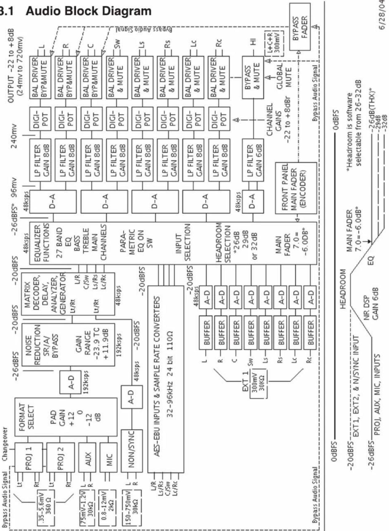
flowchart
graph TD
    A["Bypass Audio Signal"] --> B["PROJ 1"]
    A --> C["PROJ 2"]
    A --> D["AUX"]
    A --> E["MIC"]
    A --> F["NON/SYNC"]
    B --> G["FORMAT SELECT"]
    C --> H["MAP GAIN + 12 0 -12 dB"]
    D --> I["GAIN RANGE -23.9 TC + 11.9 dB"]
    E --> J["L/R"]
    F --> K["L/R"]
    G --> L["NOISE REDUCTION SR/A/BYPASS"]
    H --> M["MATRIX DECODER, DELAY, ANALYZER, GENERATOR"]
    I --> N["L/R"]
    J --> O["L/R"]
    K --> P["L/R"]
    L --> Q["48kbps"]
    M --> R["48kbps"]
    N --> S["48kbps"]
    O --> T["48kbps"]
    P --> U["48kbps"]
    Q --> V["48kbps"]
    R --> W["48kbps"]
    S --> X["48kbps"]
    T --> Y["EQUALIZER FUNCTIONS 27 BANDEQ BASS TREBLE MAIN CHANNELS"]
    U --> Z["PARAMETRIC EQ ON SW"]
    V --> AA["INPUT SELECTION"]
    W --> AB["HEADROOM SELECTION *26dB 29dB or 32dB"]
    X --> AC["MAIN FADER 7.0 = -6.0dB*"]
    Y --> AD["FRONT PANEL MAIN FADER (ENCODER)"]
    Z --> AE["D-A"]
    AA --> AF["D-A"]
    AB --> AG["D-A"]
    AC --> AH["D-A"]
    AD --> AI["D-A"]
    AE --> AJ["D-A"]
    AF --> AK["D-A"]
    AG --> AL["D-A"]
    AH --> AM["D-A"]
    AI --> AN["D-A"]
    AJ --> AO["D-A"]
    AK --> AP["D-A"]
    AL --> AQ["D-A"]
    AM --> AR["D-A"]
    AN --> AS["D-A"]
    AO --> AT["D-A"]
    AP --> AU["D-A"]
    AQ --> AV["D-A"]
    AR --> AW["D-A"]
    AS --> AX["D-A"]
    AT --> AY["D-A"]
    AU --> AZ["D-A"]
    AV --> BA["D-A"]
    AW --> BB["D-A"]
    AX --> BC["D-A"]
    AY --> BD["D-A"]
    AZ --> BE["D-A"]
    BA --> BF["D-A"]
    BB --> BG["D-A"]
    AC --> BH["D-A"]
    AD --> BI["D-A"]
    AE --> BJ["D-A"]
    AF --> BK["D-A"]
    AG --> BL["D-A"]
    AH --> BM["D-A"]
    AI --> BN["D-A"]
    AJ --> BO["D-A"]
    AK --> BP["D-A"]
    AL --> BQ["D-A"]
    AM --> BR["D-A"]
    AN --> BS["D-A"]
    AO --> BT["D-A"]
    AP --> BU["D-A"]
    AQ --> BV["D-A"]
    AS --> BW["D-A"]
    AT --> BX["D-A"]
    AU --> BY["D-A"]
    AV --> BZ["D-A"]
    AW --> CA["D-A"]
    AX --> CB["D-A"]
    AY --> CC["D-A"]
    AZ --> CD["D-A"]
    BA --> CE["D-A"]
    BB --> CF["D-A"]
    AC --> CG["D-A"]
    AD --> CH["D-A"]
    AE --> CI["D-A"]
    AF --> CJ["D-A"]
    AG --> CK["D-A"]
    AH --> CL["D-A"]
    AI --> CM["D-A"]
    AJ --> CN["D-A"]
    AK --> CO["D-A"]
    AL --> CP["D-A"]
    AM --> CQ["D-A"]
    AN --> CR["D-A"]

flowchart
graph TD
    A["REVERSE SCAN READER"] --> B["PROJ. 1"]
    C["CONVENTIONAL READER"] --> D["PROJ. 2"]
    E["BYPASS"] --> F["AUX."]
    G["AUXILIARY 2 CH SOURCE"] --> H["MIC."]
    I["CD PLAYER"] --> J["NON/SYNC"]
    K["NOISE REDUCTION"] --> L["NEER"]
    M["Matrix"] --> N["FORMAT"]
    O["EQ/CH GAIN"] --> P["****L"]
    Q["SUB GAIN"] --> R["****C"]
    S["SUB FREQ"] --> T["****R"]
    U["LR"] --> V["****LS"]
    W["RS"] --> X["****RS"]
    Y["Ls/Rs Bsl/Bsr OPTICAL SURROUND DELAY"] --> Z["Digital INPUT MAIN & SURROUND DELAYS"]
    AA["MAIN FADER"] --> AB["BYPASS/MUTE"]
    AC["Hearing Impaired"] --> AD["Power AMPS"]
    AE["Analog Input Block Diagram"] --> AF["Lc*"]
    AE --> AG["Rc*"]
    AE --> AH["Ls"]
    AE --> AI["Bsl"]
    AE --> AJ["Bsr"]
    AE --> AK["R"]
    AE --> AL["C"]
    AE --> AM["R"]
    AN["3:2 Two-Channel Inputs"] --> AO["POWER AMPS"]
    AP["Reversible Signal"] --> AQ["Power Amps"]
    AR["Signal Path"] --> AS["Power Amps"]
    AT["Signal Path"] --> AU["Power Amps"]
    AV["Signal Path"] --> AW["Power Amps"]
    AX["Signal Path"] --> AY["Power Amps"]
JSD-80 PROCESSOR
3.3
Eight-Channel
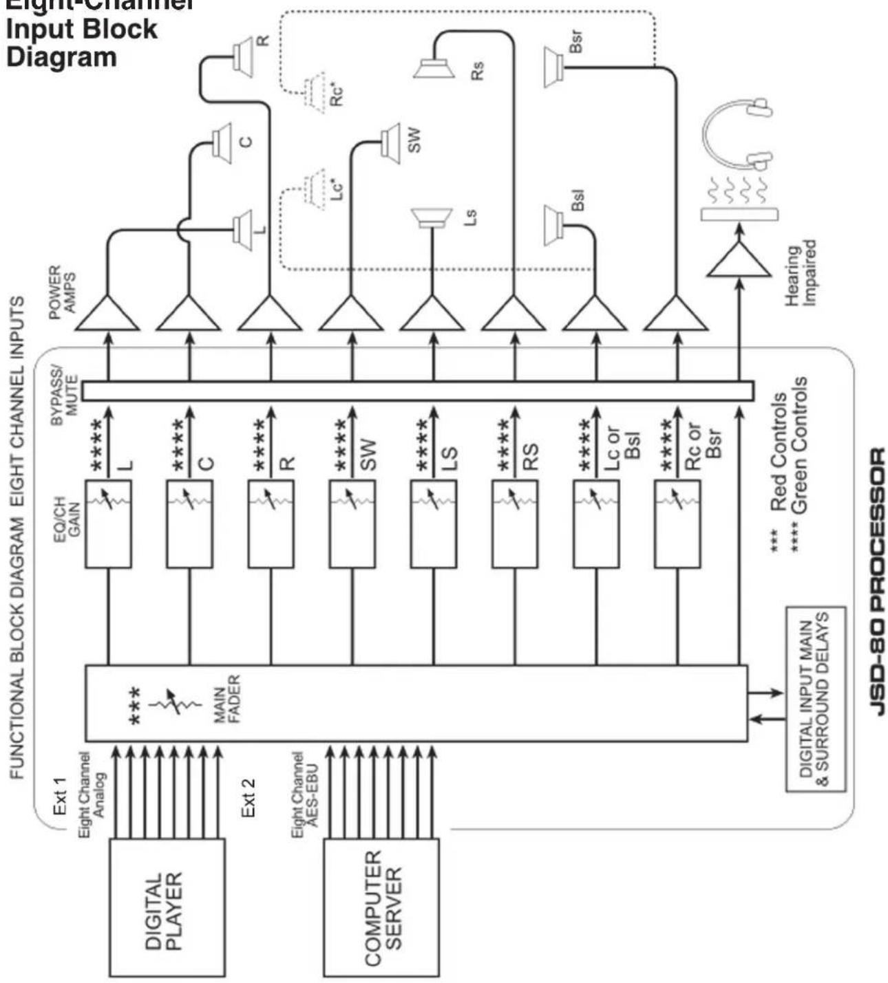
flowchart
graph TD
    subgraph Functional Block Diagram
        A1["Power AMPS"] --> B1["BYPASS/MUTE"]
        A2["EQ/CH GAIN"] --> B2["EO/CH GAIN"]
        A3["EO/CH GAIN"] --> B3["EO/CH GAIN"]
        A4["EO/CH GAIN"] --> B4["EO/CH GAIN"]
        A5["EO/CH GAIN"] --> B5["EO/CH GAIN"]
        A6["EO/CH GAIN"] --> B6["EO/CH GAIN"]
        A7["EO/CH GAIN"] --> B7["EO/CH GAIN"]
        A8["EO/CH GAIN"] --> B8["EO/CH GAIN"]
        A9["EO/CH GAIN"] --> B9["EO/CH GAIN"]
        A10["EO/CH GAIN"] --> B10["EO/CH GAIN"]
        A11["EO/CH GAIN"] --> B11["EO/CH GAIN"]
        A12["EO/CH GAIN"] --> B12["EO/CH GAIN"]
        A13["EO/CH GAIN"] --> B13["EO/CH GAIN"]
        A14["EO/CH GAIN"] --> B14["EO/CH GAIN"]
        A15["EO/CH GAIN"] --> B15["EO/CH GAIN"]
        A16["EO/CH GAIN"] --> B16["EO/CH GAIN"]
        A17["EO/CH GAIN"] --> B17["EO/CH GAIN"]
        A18["EO/CH GAIN"] --> B18["EO/CH GAIN"]
        A19["EO/CH GAIN"] --> B19["EO/CH GAIN"]
        A20["EO/CH GAIN"] --> B20["EO/CH GAIN"]
        A21["EO/CH GAIN"] --> B21["EO/CH GAIN"]
        A22["EO/CH GAIN"] --> B22["EO/CH GAIN"]
        A23["EO/CH GAIN"] --> B23["EO/CH GAIN"]
        A24["EO/CH GAIN"] --> B24["EO/CH GAIN"]
        A25["EO/CH GAIN"] --> B25["EO/CH GAIN"]
        A26["EO/CH GAIN"] --> B26["EO/CH GAIN"]
        A27["EO/CH GAIN"] --> B27["EO/CH GAIN"]
        A28["EO/CH GAIN"] --> B28["EO/CH GAIN"]
        A29["EO/CH GAIN"] --> B29["EO/CH GAIN"]
        A30["EO/CH GAIN"] --> B30["EO/CH GAIN"]
        A31["EO/CH GAIN"] --> B31["EO/CH GAIN"]
        A32["EO/CH GAIN"] --> B32["EO/CH GAIN"]
        A33["EO/CH GAIN"] --> B33["EO/CH GAIN"]
        A34["EO/CH GAIN"] --> B34["EO/CH GAIN"]
        A35["EO/CH GAIN"] --> B35["EO/CH GAIN"]
        A36["EO/CH GAIN"] --> B36["EO/CH GAIN"]
        A37["EO/CH GAIN"] --> B37["EO/CH GAIN"]
        A38["EO/CH GAIN"] --> B38["EO/CH GAIN"]
        A39["EO/CH GAIN"] --> B39["EO/CH GAIN"]
        A40["EO/CH GAIN"] --> B40["EO/CH GAIN"]
        A41["EO/CH GAIN"] --> B41["EO/CH GAIN"]
        A42["EO/CH GAIN"] --> B42["EO/CH GAIN"]
        A43["EO/CH GAIN"] --> B43["EO/CH GAIN"]
        A44["EO/CH GAIN"] --> B44["EO/CH GAIN"]
        A45["EO/CH GAIN"] --> B45["EO/CH GAIN"]
        A46["EO/CH GAIN"] --> B46["EO/CH GAIN"]
        A47["EO/CH GAIN"] --> B47["EO/CH GAIN"]
        A48["EO/CH GAIN"] --> B48["EO/CH GAIN"]
        A49["EO/CH GAIN"] --> B49["EO/CH GAIN"]
        A50["EO/CH GAIN"] --> B50["EO/CH GAIN"]
        A51["EO/CH GAIN"] --> B51["EO/CH GAIN"]
        A52["EO/CH GAIN"] --> B52["EO/CH GAIN"]
        A53["EO/CH GAIN"] --> B53["EO/CH GAIN"]
        A54["EO/CH GAIN"] --> B54["EO/CH GAIN"]
        A55["EO/CH GAIN"] --> B55["EO/CH GAIN"]
        A56["EO/CH GAIN"] --> B56["EO/CH GAIN"]
        A57["EO/CH GAIN"] --> B57["EO/CH GAIN"]
        A58["EO/CH GAIN"] --> B58["EO/CH GAIN"]
        A59["EO/CH GAIN"] --> B59["EO/CH GAIN"]
        A60["EO/CH GAIN"] --> B60["EO/CH GAIN"]
    end

    subgraph Functional Block Diagram
        C1["BYPASS/MUTE"]
        D1["EQ/CH GAIN"]
        E1["EOLG"]
    end

    subgraph Functional Block Diagram
        F1["MAIN FADER"]
    end

    subgraph Functional Block Diagram
        F2["MAIN CHANGES"]
    end

    subgraph Functional Block Diagram
        F3["MAIN CHANGES"]
    end

    subgraph Functional Block Diagram
        F4["MAIN CHANGES"]
    end

    subgraph Functional Block Diagram
        F5["MAIN CHANGES"]
    end

    subgraph Functional Block Diagram
        F6["MAIN CHANGES"]
    end

    subgraph Functional Block Diagram
        F7["MAIN CHANGES"]
    end

    subgraph Functional Block Diagram
        F8["MAIN CHANGES"]
    end

    subgraph Functional Block Diagram
        F9["MAIN CHANGES"]
    end

    subgraph Functional Block Diagram
        F10["MAIN CHANGES"]
    end

    subgraph Functional Block Diagram
        F11["MAIN CHANGES"]
    end

    subgraph Functional Block Diagram
        F12["MAIN CHANGES"]
    end

    subgraph Functional Block Diagram
        F13["MAIN CHANGES"]
    end

    subgraph Functional Block Diagram
        F14["MAIN CHANGES"]
    end

    subgraph Functional Block Diagram
        F15["MAIN CHANGES"]
    end

    subgraph Functional Block Diagram
        F16["MAIN CHANGES"]
    end

    subgraph Functional Block Diagram
        F17["MAIN CHANGES"]
    end

    subgraph Functional Block Diagram
        F18["MAIN CHANGES"]
    end

    subgraph Functional Block Diagram
        F19["MAIN CHANGES"]
    end

    subgraph Functional Block Diagram
        F20["MAIN CHANGES"]
    end

    subgraph Functional Block Diagram
        F21["MAIN CHANGES"]
    end

    subgraph Functional Block Diagram
        F22["MAIN CHANGES"]
    end

    subgraph Functional Block Diagram
        F23["MAIN CHANGES"]
    end

    subgraph Functional Block Diagram
        F24["MAIN CHANGES"]
    end

    subgraph Functional Block Diagram
        F25["MAIN CHANGES"]
    end

    subgraph Functional Block Diagram
        F26["MAIN CHANGES"]
    end

    subgraph Functional Block Diagram
        F27["MAIN CHANGES"]
    end

    subgraph Functional Block Diagram
        F28["MAIN CHANGES"]
    end

    subgraph Functional Block Diagram
        F29["MAIN CHANGES"]
    end

    subgraph Functional Block Diagram
        F30["MAIN CHANGES"]
    end

    subgraph Functional Block Diagram
        F31["MAIN CHANGES"]
    end

    subgraph Functional Block Diagram
        F32["MAIN CHANGES"]
    end

    subgraph Functional Block Diagram
        F33["MAIN CHANGES"]
    end

    subgraph Functional Block Diagram
        F34["MAIN CHANGES"]
    end

    subgraph Functional Block Diagram
        F35["MAIN CHANGES"]
    end

    subgraph Functional Block Diagram
        F36["MAIN CHANGES"]
    end

    subgraph Functional Block Diagram
        F37["MAIN CHANGES"]
    end

    subgraph Functional Block Diagram
        F38["MAIN CHANGES"]
    end

    subgraph Functional Block Diagram
        F39["MAIN CHANGES"]
    end

    subgraph Functional Block Diagram
        F40["MAIN CHANGES"]
    end

    subgraph Functional Block Diagram
        F41["MAIN CHANGES"]
    end

    subgraph Functional Block Diagram
        F42["MAIN CHANGES"]
    end

    subgraph Functional Block Diagram
        F43["MAIN CHANGES"]
    end

    subgraph Functional Block Diagram
        F44["MAIN CHANGES"]
    end

    subgraph Functional Block Diagram
        F45["MAIN CHANGES"]
    end

    subgraph Functional Block Diagram
        F46["MAIN CHANGES"]
    end

    subgraph Functional Block Diagram
        F47["MAIN CHANGES"]
    end

    subgraph Functional Block Diagram
        F48["MAIN CHANGES"]
    end

    subgraph Functional Block Diagram
        F49["MAIN CHANGES"]
    end

    subgraph Functional Block Diagram
        F50["MAIN CHANGES"]
    end

    subgraph Functional Block Diagram
        F51["MAIN CHANGES"]
    end

    subgraph Functional Block Diagram
        F52["MAIN CHANGES"]
    end

    subgraph Functional Block Diagram
        F53["MAIN CHANGES"]
    end

    subgraph Functional Block Diagram
        F54["MAIN CHANGES"]
    end

    subgraph Functional Block Diagram
        F55["MAIN CHANGES"]
    end

    subgraph Functional Block Diagram
        F56["MAIN CHANGES"]
    end

    subgraph Functional Block Diagram
        F57["MAIN CHANGES"]
    end

    subgraph Functional Block Diagram
        F58["MAIN CHANGES"]
    end

    subgraph Functional Block Diagram
        F59["MAIN CHANGES"]
    end

    subgraph Functional Block Diagram
        F60["MAIN CHANGES"]
    end

    subgraph Functional Block Diagram
        F61["MAIN CHANGES"]
    end

    subgraph Functional Block Diagram
        F62["MAIN CHANGES"]
    end

    subgraph Functional Block Diagram
        F63["MAIN CHANGES"]
    end

    subgraph Functional Block Diagram
        F64["MAIN CHANGES"]
    end

    subgraph Functional Block Diagram
        F65["MAIN CHANGES"]
    end

    subgraph Functional Block Diagram
        F66["MAIN CHANGES"]
    end

    subgraph Functional Block Diagram
        F67["MAIN CHANGES"]
    end

    subgraph Functional Block Diagram
        F68["MAIN CHANGES"]
    end

    subgraph Functional Block Diagram
        F69["MAIN CHANGES"]
    end

    subgraph Functional Block Diagram
        F70["MAIN CHANGES"]
    end

    subgraph Functional Block Diagram
        F71["MAIN CHANGES"]
    end

    subgraph Functional Block Diagram
        F72["MAIN CHANGES"]
    end

    subgraph Functional Block Diagram
        F73["MAIN CHANGES"]
    end

    subgraph Functional Block Diagram
        F74["MAIN CHANGES"]
    end

    subgraph Functional Block Diagram
        F75["MAIN CHANGES"]
    end

    subgraph Functional Block Diagram
        F76["MAIN CHANGES"]
    end

    subgraph Functional Block Diagram
        F77["MAIN CHANGES"]
    end

    subgraph Functional Block Diagram
        F78["MAIN CHANGES"]
    end

    subgraph Functional Block Diagram
        F79["MAIN CHANGES"]
    end

    subgraph Functional Block Diagram
        F80["MAIN CHANGES"]
    end
3.4
Control Block
Diagram

flowchart
graph TD
    A["FUNCTIONAL BLOCK DIAGRAM, CONTROL"] --> B["AUTOMATION"]
    B --> C["RS232"]
    C --> D["RS232"]
    D --> E["AUTOMATION I/O"]
    E --> F["LATCHING SHIFT REGISTER"]
    F --> G["PIC"]
    G --> H["EIGHT BIT PARALLEL"]
    H --> I["2 CHANNEL QUADRATURE"]
    I --> J["MAIN FADER"]
    G --> K["PART 1"]
    G --> L["PART 2"]
    G --> M["PART 3"]
    G --> N["PART 4"]
    G --> O["PART 5"]
    G --> P["PART 6"]
    G --> Q["PART 7"]
    G --> R["PART 8"]
    G --> S["PART 9"]
    G --> T["PART 10"]
    G --> U["PART 11"]
    G --> V["PART 12"]
    G --> W["PART 13"]
    G --> X["PART 14"]
    G --> Y["PART 15"]
    G --> Z["PART 16"]
    G --> AA["PART 17"]
    G --> AB["PART 18"]
    G --> AC["PART 19"]
    G --> AD["PART 20"]
    G --> AE["PART 21"]
    G --> AF["PART 22"]
    G --> AG["PART 23"]
    G --> AH["PART 24"]
    G --> AI["PART 25"]
    G --> AJ["PART 26"]
    G --> AK["PART 27"]
    G --> AL["PART 28"]
    G --> AM["PART 29"]
    G --> AN["PART 30"]
    G --> AO["PART 31"]
    G --> AP["PART 32"]
    G --> AQ["PART 33"]
    G --> AR["PART 34"]
    G --> AS["PART 35"]
    G --> AT["PART 36"]
    G --> AU["PART 37"]
    G --> AV["PART 38"]
    G --> AW["PART 39"]
    G --> AX["PART 40"]
    G --> AY["PART 41"]
    G --> AZ["PART 42"]
    G --> BA["PART 43"]
    G --> BB["PART 44"]
    G --> BC["PART 45"]
    G --> BD["PART 46"]
    G --> BE["PART 47"]
    G --> BF["PART 48"]
    G --> BG["PART 49"]
    G --> BH["PART 50"]
    G --> BI["PART 51"]
    G --> BJ["PART 52"]
    G --> BK["PART 53"]
    G --> BL["PART 54"]
    G --> BM["PART 55"]
    G --> BN["PART 56"]
    G --> BO["PART 57"]
    G --> BP["PART 58"]
    G --> BQ["PART 59"]
    G --> BR["PART 60"]
    G --> BS["PART 61"]
    G --> BT["PART 62"]
    G --> BU["PART 63"]
    G --> BV["PART 64"]
    G --> BW["PART 65"]
    G --> BX["PART 66"]
    G --> BY["PART 67"]
    G --> BZ["PART 68"]
    G --> CA["PART 69"]
    G --> CB["PART 70"]
    G --> CC["PART 71"]
    G --> CD["PART 72"]
    G --> CE["PART 73"]
    G --> CF["PART 74"]
    G --> CG["PART 75"]
    G --> CH["PART 76"]
    G --> CI["PART 77"]
    G --> CJ["PART 78"]
    G --> CK["PART 79"]
    G --> CL["PART 80"]
4.1 Input Module
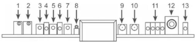
The Input Module contains the projector preamps plus Non-Sync, Auxiliary and Mic inputs. It also contains the bypass circuit. Two high-power DSPs implement "A" type and "SR" noise reduction. A third DSP is used for the matrix decoder, slit eq analyze and pink noise generator. Test points perm connection of an oscilloscope to align the film projector's analog reader. LEDs indicate the presence of left, center, right and surround signals. Bicolor LEDs indicate the correct level for LT and RT preamp inputs. A status LED indicates the module is in a "fault" condition.
flowchart
graph TD
    A["1"] --> B["Φ"]
    C["2"] --> D["Φ"]
    E["3"] --> F["Φ"]
    G["4"] --> H["Φ"]
    I["5"] --> J["Φ"]
    K["6"] --> L["Φ"]
    M["7"] --> N["Φ"]
    O["8"] --> P["Φ"]
    Q["9"] --> R["Φ"]
    S["10"] --> T["Φ"]
    U["11"] --> V["Φ"]
    W["12"] --> X["Φ"]
    Y["13"] --> Z["Φ"]
- Projector 1 Bypass Level Adjust
- Projector 2 Bypass Level Adjust
- Left Channel Test Point
- Projector 1 Indicator green LED
- Right Channel Test Point
- Projector 2 Indicator red LED
- Ground Test Point
- Bypass level test point
- *Left channel level indication.
- *Right channel level indication.
- Signal presence LEDs left to right: L, C, R, Surround
- THX pink noise enable jack
- Status: Fault red LED
*A red color indicates signal is "low," a green color means OK, flashing red indicates "high."
4.2 Output Module
The Output Module contains the eight-channel analog and AES-EBU input circuitry. It also contains the balanced output circuitry. Two high-power DSPs implement seven channels of 1/3 octave equalization, plus a parametric subwoofer equalizer. Test point on each channel permit connection of diagnostic instruments. Level LEDs indicate the presence of signals. A status LED indicates the module is in a “fault” condition.

- Test Point. Gnd.
2-16. Signal presence LEDs left to right: L, C, R, Sw, Ls, Rs, Bsl, Bsr, (or Lc, Rc)
3-17. Test point left to right: L, C, R, Sw, Ls, Rs, Bsl, Bsr (or Lc, Rc) - Status Light
4.3 Control Module
The Control Module manages all the communication in the unit. It also contains the automation interface, bypass volume and remote volume circuitry.
On the Control Module is a “Non-Volatile Flash” memory card known as the “Personality Module.” This module contains a copy of all the installation alignment settings made to the unit. If there is a failure of any the three internal modules, a technician w be able to re-install the original alignment settings without requiring a laptop.

- Personality Module
- Write Protect Switch
- Write Protect Indicator LED
- Restore Switch
- Restore
- Fault
⚠️ Note: When using the laptop interface, prior to saving the configuration and parameters to the Personality Module (1), you must slide the Write Protect Switch (2) to the left (OFF) to allow writing to that module. Please remember to turn the Write Protect Switch (2) to “ON after the data is saved to the Personality Module (1).

-
Mono signal from 35mm analog sound track
-
Stereo signal with "A" type noise reduction from 35mm
soundtrack
- Stereo signal with "SR" type noise reduction from 35mm
soundtrack
Ext. 1: Eight-channel analog input
Ext. 2: Eight-channel AES/EBU digital input
Non/Sync: Two-channel input with fade in, fade out
-
Aux: Two-channel input
-
Mic: for paging purposes
-
Mute: globally mutes all outputs
-
Level Indicator: also used for setting projector gains
-
Power Switch: when off, unit goes into bypass mode.
-
Bypass LED: indicates Bypass is active.
-
Power LEDs: indicates status of all internal supplies.
-
Main Fader Control: also used for setting projector gains.
5.1 Overview
The front panel allows the operator to manual select formats and adjust the main fader. An L numerical readout indicates fader level. Status LEDs indicate presence of power supplies. The unit is placed into the bypass mode by turning off the main power switch. A removable panel allows access to service or replace modules.
5.2 Adjusting Format Levels
Each format has a preset level. These presets can be set with a laptop or directly on the front panel. Pressing and holding the appropriate format button and rotating the main fader will change the preset level for that format. The LF display will indicate the preset level number
5.3 Adjusting Projector Gains
- Turn off the processor.
- Hold down the "Mute" button and turn the power on.
- Continue to hold the "Mute" button until the LED display indicates 1.1 which means Projector 1, Left channel.
- Run a Cat 69T tone loop on the projector.
- Watch the LED level indication on the Input Module: (9 & 10).

-
If the left indicator (9) is red, the signal is too low. Rotate the main fader control clockwise to raise the level. When the level is correct, the indicator (9) will turn green. A flashing red means that the signal is too high.
-
When the left indicator is green, press the "Mute" button to signal OK. The display will change to 1.2 (Projector 1, Right Channel). Adjust the main fader until the right (10) indicator turns green. Press "Mute." The optimum setting is first click from solid red to solid green.
-
The LED display will show 2.1 (Projector 2, Left Channel). Press “Mute” when adjustment is complete. If there is no Projector 2, press “Mute” twice to return to normal operation. If there is a Projector 2, press “Mute” once and proceed to step 9.
-
The LED display will show 2.2 (Projector 2, Right Channel). Press "Mute" when the adjustment is finished
-
The last "Mute" button press will return the system to its normal operating mode. Operation will resume after six seconds.
6.1 Rear Wiring Diagram

flowchart
graph TD
    subgraph Power Amplifiers
        A["MONITOR/CROSSOVER CM-680"] --> B["POWER AMPLIFIERS"]
        B --> C["MONITOR OUTPUTS"]
        B --> D["AUX S/PDIF"]
        B --> E["AES/EBU EXTERNAL 0-8 CHANNEL DIGITAL PLAYER"]
        B --> F["CD PLAYER"]
        B --> G["VIDEO INTERMISSION PROGRAM COMPUTER SOUND CARD"]
    end

    subgraph Automated System
        H["CHANGEOVER RELAY CONNECT "XO" TO "COM" FOR PROJECTOR 2"] --> I["RS-232"]
        I --> J["AS-24VAC 50-60 Hz 40 WIRE"]
        K["AC Connector"] --> L["Auxiliary Power Supply"]
    end

    subgraph Control Systems
        M["ANALOG READER WIRING (US) DST-09"] --> N["LAPTOP OR AUTOMATION"]
        O["ANALOG READER WIRING (Europe) DST-09"] --> P["TO HEARING IMPAIRED TRANSMITTER"]
        Q["Solar Cell Wiring DST-09"] --> R["TYPICAL PROJECTION READERS"]
        S["TYPEKLE PROJECTION READERS"] --> T["Microphone"]
        U["PROYECTOR 1 INPUTS"] --> V["MICROPHONE INPUTS"]
        W["PROYECTOR 2 INPUTS"] --> X["N/SYNC INPUTS"]
        Y["PROYECTOR 2 INPUTS"] --> Z["AUX INPUT"]
        AA["PROYECTOR 2 INPUTS"] --> AB["SAN LUIS OEISP CO CA 93401 USA usl@silinc.com"]
    end

    subgraph Audio Outputs
        AC["R+ R- E L+ L-Audio Outputs"] --> AD["L+ L- C+ C- R+ R- Sw+Sw L+ L+ Rs+ Rs+ Bu+ Bu+ Bu+ Bu+ Bu+ Bu- (Lc)- (Rc)-"]
        AE["Ls"] --> AF["Bsi"]
        AG["C"] --> AH["Lc"]
        AI["Rc"] --> AJ["Sw"]
        AK["R"] --> AL["Bsr"]
    end

    subgraph External Channel Player
        AM["EXTERNAL 6-8 CHANNEL PLAYER"] --> AN["AUDIO"]
        AN --> AO["MONITOR OUTPUTS"]
        AO --> AP["MAIN OUTPUTS"]
        AP --> AQ["OUTPUTS CAN GO DIRECT TO AMPS"]
        AQ --> AR["SPDIF INPUTS"]
    end

    subgraph Power Amplifiers
        AS["MONITOR/CROSSOVER CM-680"] --> AT["Power Amplifiers"]
    end

    style Power Amplifiers fill:#f9f,stroke:#333
    style Audio Outputs fill:#ccf,stroke:#333
    style External Channel Player fill:#cfc,stroke:#333
    style Control Systems fill:#fcc,stroke:#333
6.2 Back Panel Input Connections
Projector Inputs
The projector inputs are connected through standard 9-pin D-type connectors. (These connectors are included with the JSD-80).
The pinout is:
- In L+
- In L-
- Shield
- In R+
- In R-
- Gnd
- Reserved
- Reserved
- Gnd
(An adapter board with setscrew terminals is available for solderless connections.)
Non-Sync Inputs - Analog
Two RCA connectors facilitate easy connection to standard CD players. A software fade in/fade out algorithm allows smooth transition between intermission music and the main program.
Auxiliary Input - Analog
Two RCA connectors are used to connect to external two-channel sources such as a sound card in a computer supplying video advertising content.
Microphone Input
The public address balanced microphone input is available on a standard 9-pin D-typ connector.
The pinout is:
- Mic in +
- Mic in -
- Reserved
- Reserved
- Chassis Gnd.
- N/C
- 9 V DC
- Gnd
- N/C
The “Mic in +” and “Mic in -” terminals are for the balanced medium-low impedance
microphone inputs. The shield of the microphone cable should be connected to chassis ground on pin 5. A 9 V DC power pin allows easy connection of electret (powered) microphones.
EXT 1 (Analog)
The Analog input is an eight-channel un balanced analog audio input from a digital soundtrack player. The 25-pin D connector is compatible with most decoders. Input level should be 300 mV for all channels. Se Section 12.
EXT 2 (Digital)
The Digital input is a digital domain input configured for eight channels (Four AES-EBU pairs with sample rate from 32 to 96 kHz). Requires optional AES-EBU Module (DI85). See Section 12
Non/Sync Inputs - Digital
Requires optional Module (D183). An RCA jack accepts S/PDIF inputs from CD, DVD, or computer sound cards. Sample rates from 32-96 kHz PCM are supported, AC3 bitstreams are also supported.
The DI83 module in this processor, which decodes Dolby® Digital bitstreams, is not intended for 35mm fi lm. The DI83 is intended for alternative content only.
Auxiliary Inputs - Digital
Requires optional Module (DI83). An RCA jack accepts S/PDIF inputs from CD, DVD, or computer sound cards. Sample rates from 32-96 kHz PCM are supported. AC3 bitstreams also are supported.
6.3 Back Panel Signal Output Connections
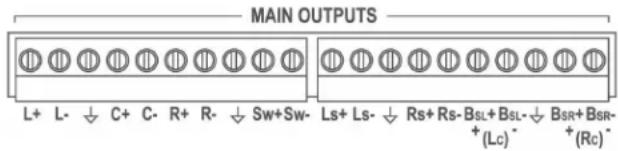
Main Outputs
These are the main processor outputs to connect to the power amplifiers. The outputs are balanced, and all have a corresponding ground terminal. Use two-conductor shielded cable for each channel. The shield should usually be connected to ground at the power amplifier end only
Monitor Outputs
This is a 25-pin D-type connector containing the line output signals for all eight channels. It can be connected directly to any Ultra Stereo "CM" series monitors. The pinout for this connector is in Section 12.
Hearing Impaired Output
This line-level output is the sum of the left, center, and right channels. It can be connected to an “Ultra Phonic” or other hearing impaired system. Output level is approximately 300 mV
Back Panel Automation Connections
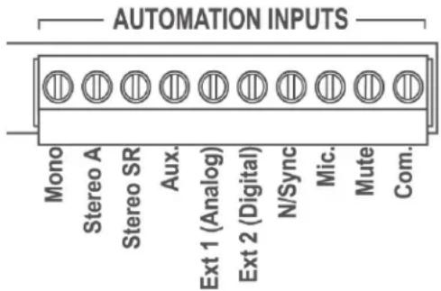
Automation Inputs (Phoenix Connector)
These are active low-contact closure input to remotely trigger the JSD-80. There are nine automation inputs; one for each of the eight JSD-80 operating formats, and a "Mute" input. These are intended to be momentar contact closures. The "Mute" function is released by selecting (or re-selecting) one of the main input formats.
The Automation common terminal is isolated from the system ground through an internal 10 Ohm resistor to minimize group loop problems.
Note: When wiring the automation in puts, use the Com terminal, not a ground terminal.
Automation (DB-25)
This 25-pin D-type connector contains most (not all!) of the automation input and output signals. The pinout for this connector is in Section 12.
Note: An adapter is available to convert to the DTS automation pinout (DTS-6D).
LEDs for monitoring the status of the JSD-8 can be connected in series with a 1k resist from +5 V at pin 13, to any of these outputs. See Section 12.
Bypass Power Input
The JSD-80 uses an external 16 V AC @ 500 mA power supply to power the bypass circuit.
Remote Fader Input
Two normally open switches can be used to implement a remote fader. One button increases level, the other decreases level. The range is limited to 4.0 - 9.0 on the main fader. See Section 10.3
Changeover
The JSD-80 includes dual preamplifiers for use in two-projector changeover systems. Connecting the "XO" terminal to "Common mutes the Projector 1 input and selects Projector 2. This must be a maintained closure.
RS232 Port
A standard 9-pin D-type connector connect to a host PC computer. The cable should be a standard male to female “straight through” type. The port also can be used for remote fader and automation functions See Section 12.
7.1 Installation Procedure
Begin by placing the JSD-80 Laptop Interface Software CD into your CD-ROM drive. The software is compatible with Windows only. The installation program should start automatically within a few seconds. If it does not, you will need to run "Setup.exe" from the root directory of your CD-ROM drive. Either double click the "Setup.exe" icon or click the Windows "Start" button and select "Run..." Now enter "X:\setup.exe" (where "X:" is your CD-ROM drive), then click the "OK" button. Follow the instructions in the installation software.
7.2 The Opening Screen

Double click on the JSD icon on the desktop.
The opening screen appears.
The opening screen is comprised of the Menu Bar, the Tool Bar, tabs for accessing software functions and, on the Profi le tab, a system information entry area.

At the top of the opening screen is the Menu Bar. The menu bar gives access to various functions. These functions are duplicated on the Toolbar (with the exception of "Language"), and through keyboard key combinations.

The toolbar consists of graphic icons allowing you access to various functions. Holding the mouse pointer over any of the icons will give you a "tool tip" describing function of the icon. The horizontal slider at the far right is the main level control (or Main Fader). The level may be changed from the main screen by placing the cursor ove:
the slider, holding down the left button an moving the mouse.

Below the toolbar are tabs for accessing various operational modes. These tabs will be described in order from left to right.
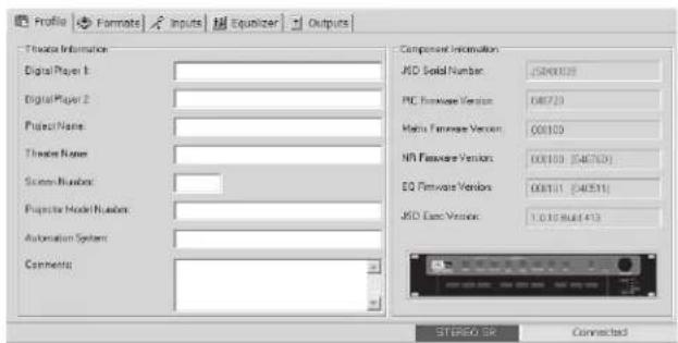
7.3 Profi le Screen
On the first tab, there are several windows for entering information about your system and peripheral equipment. This information is stored in the .JSD-80 and also can be stored on the computer or the device used to set up the unit. This information is not used by the unit functions but can be extremely valuable to technicians for the purposes of repair and re-alignment or in case of the necessity of a factory repair. You can enter this information at any time whether connected to the .JSD or not and save it to disk for eventual loading onto the .JSD. The "Component Information" boxes are filled in at the factory and are not editable by the end user. At the bottom right of the tab are the connection status bar and the format status bar. No matter which tab you are working in, the format status bar will always indicate in which format the processor is currently operating
Note: When the computer is connected to and controlling the JSD-80, the front panel controls will no function, with the exception of the Mute button.
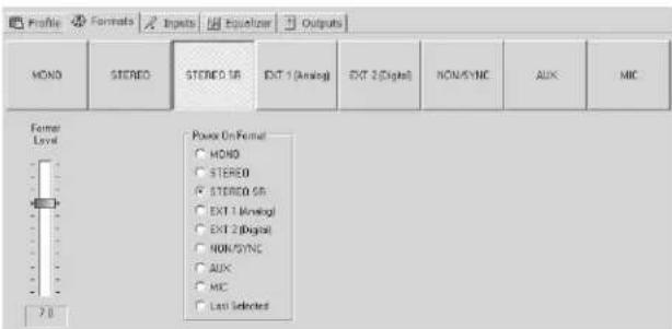
7.4 Formats Screen.
This is where you set the processor's mod of operation. Anyone familiar with the operation of a motion picture venue should also be familiar with the above formats. Any of the formats may be designated the "Power On" format which means that when the power is turned on, the processor will "wake up" in that mode. The Non/Sync and Aux inputs have the option of being either an analog or S/PDIF input. The Mic input can be routed to either the center or the surround channels. The fader at the left of the window allows you to pre-set the level of a particular mode. The master level will follow that setting. When you go to another mode and set its level to whatever you desire, upon your return to the original mode, the level will be the same as you left it. Along with the standard "Power On" choices, which are visible in all format selections, a "Digital Fallback" selection appears whenever you select Ext 2 (Digital). This allows you to select a mode to automatically default to, should the digital track become interrupted for any reason. A Digital Delay button (which brings up a separate screen on which you can set input and surround delay) also becomes visible in Ext 2 mode well as when S/PDIF is selected in either the Non/Sync or Aux formats. See Section 8.8.

7.5 Inputs Screen.
There are two sections.
The first section is the Preamp Controls station and contains buttons to select either Projector 1 or 2 level settings for the Left and Right preamps (with accompanying level indicators), Slit EQ & Mono EQ and the Slit EQ Analyzer screen which is dealt with in detail in Section 7.8. This tab is where the alignment is accomplished for the optical preamp (A Chain), and is vital for accurate optical performance.
The second section is a matrix controls section for setting the delay & gain of the surround channel, and the gain & frequency of the subwoofer. The level functions are accessed by placing the pointer over the desired slider's button, holding down the left mouse button and moving the mouse. Note that when a slider is selected, it is highlighted and will stay that way until another slider is selected. The sliders (once they are selected) also may be manipulated by using the up or down arrow keys; the left/right arrow keys will select the sliders on the left or right of the one initially chosen. At the bottom of the slider is a box that states numerically the position in dB of the slider

7.6 Equalizer Screen.
This is used for all equalization of the auditorium. With the radio buttons, you may select the channel to be equalized. The channels consist of Left, Center, Right, Left Surround, Right Surround, Subwoofer and two additional channels. (Note: When you select Subwoofer, a separate screen appears containing a Sub Bass Parametric EQ.)
The sliders also will respond to the push c
an "up" or "down" arrow key and, for every push, the level will change .1 dB. Clicking on the button labeled "Flat" will restore all slider settings to the mid point and will wait you (if you accidentally hit it) before acting on the command.
Note: If a channel should appear highlighted in red, it indicates that the channel has been muted on the Outputs Screen (see Section 7.7).

7.7 Outputs Screen.
This is where, during the alignment process the output levels are set for the various channels. A signal generator is available which can be set to four different modes. To select the particular generator function choose the function with the radio buttons on the bottom of the screen. To assign a particular channel to receive generator output, a box is available below the slider. These boxes may also be utilized to Mute or Invert the channel. The faders change in 0.5 dB increments
Note: When using the generator, the default mode allows one active channel at a time. Holding down the
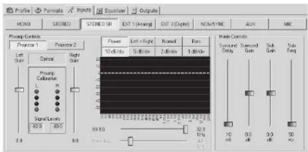
7.8 Slit EQ Analyzer Screen
To the right of the Preamp Level Faders is screen with annotations on the bottom and left side and buttons at the top. This is the Real Time Analyzer built into the JSD-80. You must be connected to the JSD-80 and it must have a signal source before it can become functionally effective. Move the mouse arrow over one of the buttons and a pointer appears. Click the "Power" button and a line appears across the screen. You can utilize the Real Time Analyzer in the following ways: utilizing the third button from the top left, you can select either Normal or Sum & Diff. In the "Normal" mode, you have the option of selecting (with the second to button), either Left, Right, or Left + Right. The Sum & Diff mode, you can select (with the second top button), either Sum, Diff or Sum + Diff. You can view the performance the left channel and right channel, Sum or Diff as either bars or lines. On the left hand side of the screen are gradations measured in decibels. As you can see, they often extend below the level of the screen. Moving the mouse pointer over these gradations and holding down button one, a pointer appears once again, with an accompanying arrow. You can move the numbers and the screen up to view the signal, down to a level of -50 dB and up to +20 dB if so desire Double click on the screen and it expands a larger representation that can be seen at greater distance. The larger screen can be maneuvered on the computer's screen access controls.
7.9 Creating, Saving and Loading Configuration Files
Use the "New" command to create a custom configuration file starting with factory defaults.
Use the “Save” or “Save As” command to save your custom configuration file to the hard disk.
You may load a previously saved file by using the "File," "Open" command and selecting the desired configuration file. If you are connected to the unit, the parameters will be automatically uploaded.
(See also: System Restore From Personality Module, Section 10.4.)
Please take the time to familiarize yourself with the laptop interface controls and screens. Next establish communication with the JSD-80 using a standard RS232 cable. Select the "Connect" icon on the toolbar and everything is as it should be, the computer will connect with the JSD-80.

When you first accessed the JSD software, the small window in the lower right hand corner of the main window looked like this:
Disconnected
Once you connect to the JSD, the compute will download all the data stored on the JSD-80 to the laptop's memory. This data can consist of Preamp Parameters, EQ Parameters, Front Panel Parameters and Profi le Information. Once that action has taken place, the small window will change to this:
Connected
You are now ready to set up the JSD-80 If you are setting up the JSD-80 for the first time, you may want to fill in the particular of the venue in the “Theatre Information” boxes provided in the Profile tab. They
may be filled in and edited like a normal text file
The “Component Information” boxes are filled in at the factory and are not editable by the end user.
Note: As stated previously, this information is not functional insofar as the operation of the processor is concerned but can aid you greatly in future endeavors.
At any time during the Profile entry or setup procedures, the information from those tasks may be saved to the laptop's hard drive or other convenient data storage medium by utilizing the "Save" function an providing a path and file name
After completion of the alignment procedure (see Section 8), the complete system configuration may be saved to the laptop's hard drive or other data storage medium by utilizing the "Save" function and providing a path and file name
Section 8. "A" Chain Alignment
8.1 Preparing The Sound Head
- Clean the soundhead optics thoroughly. If the film guide rollers are worn, replace them. Excessive side to side weave will cause insurmountable problems for the stereo circuitry and must be corrected prior to installation.
- If the exciter lamp is old or blackened inside, replace it. Make sure the lamp operating at a voltage greater than 60 of its rating. We strongly recommend converting the projector to be compatible with the new cyan soundtracks with a red LED lamp source such as an ULTRA*STEREO Jaxlight or RSTR Reverse Scan Reader.
- With the mono solar cell in the projector, run the SMPTE BUZZ TRACK fi lm and align the guide rollers for minimum output.
- For stereo installations, remove the mono solar cell and place a white car about an inch away from the sound lens. The image of the exciter lamp fi lament should look as in the illustration below. If necessary, raise or lower the lamp and move it in and out until the fi lament is centered in the spot of light. This will insure that the slit is evenly illuminated, thereby producing the least distortion in playback.

natural_image
Diagram of a light bulb connected to a cylindrical tube with a coiled wire inside (no text or symbols)8.2 Alignment of Solar Cell and Preamplifi e
- Mount the stereo solar cell on the projector and position the bracket, so that the slit image hits the upper part of the cell. The cell should be approximately 0.040 inch (1 mm) behind the film such that the slit image just fills the cell width, but does NOT spill over
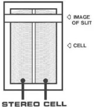
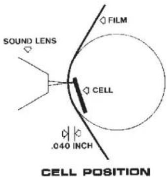
- Install the audio line from the cell to the JSD-80. Use Belden N° 8404 or equivalent four-conductor twin-shielded cable, or a pair of two-conductor shielded cables such as Belden N° 8451. (A single two-conductor or three-conductor shielded cable is not recommended.) Connect the lines to a 9-pin male D-type connector. The pinout for this connector is in Section 12. Be sure that the RED lead of the cell is connected to the "L" input terminal marked "+" and the GREEN lead of the cell is connected to the "R" input terminal marked "+" . The BLACK cell leads connect to the low "-" input terminals of BOTH Left and Right channels respectively.
Connect the shielding of the cable to the Chassis terminal (pin 3). Do not connect the shielding at the projector end. The D-9 connector should be plugged into the Projector 1 input of the JSD-80.
- Film readers with active circuits, such as a Jaxlight line amplifier or a reverse scan reader, will require a ground connection at the reader. Good results can be achieved using the drain (shield) wire of the cables listed above, however, some agencies (such as CE) prohibit using the drain conductor for this purpose. In that case, use two 3-conductor shielded cables (such as Belden N° 9939) (see Section 6.1).
- If there are two projectors, the change over is accomplished by grounding the "X-OVER" terminal. Connect a latching relay, with the appropriate rating, so that one coil is powered by the dowser circuit of Projector 1 and the other coil is powered by the dowser circuit of Projector 2. The relay contacts must be connected to the "XO" and "COM" terminals so that the contacts are closed when Projector 2 is operational.
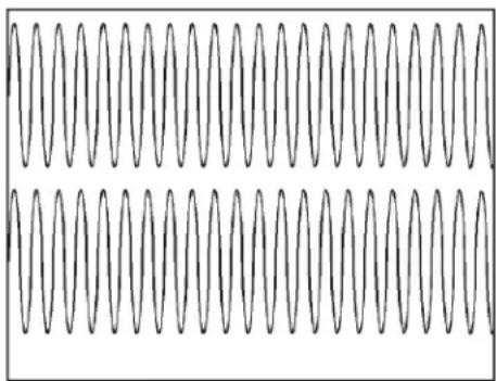
- Set the JSD-80 preamp controls so the gain is at the midpoint and the high frequency boost fi liters are at the maximum frequency (32 kHz). This can be accomplished from the JSD Laptop Interface Software. Connect a dual trace oscilloscope to the test points on the JSD-80 "Input Module" board. "Left" is RED, "Right" is GREEN, and "GND" (Audio ground) is BLACK. Run a 100% alternating left/right STEREO ALIGNMENT fi lm and move the cell in and out until the crosstalk is at a minimum on both channels as shown. It may be necessary to set the gain of the preamp roughly at this time.

natural_image
Two overlapping wavy line patterns, no text or symbols present- Run a 50% level film such as the Cat 69T or equivalent. Adjust the Left and Right level controls on Projector 1 until the preamp calibration LEDs on the input screen show two green indicator lights. Repeat the procedure for Projector 2 if applicable.
natural_image
Pure waveform pattern with no text, numbers, or symbols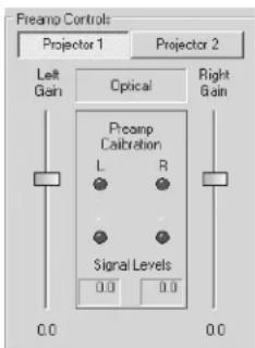
- Double check the cell alignment by running a 100% STEREO ALIGNMENT fi lm. The amplitude of the two 100% modulated waveforms should be identical (see illustration). If one is greater than the other, while the modulated waveforms of the 50% level fi lm are identical, there is a problem with the scanning beam. Either the slit is not uniformly illuminated along its length or the scanning beam is not in perfect alignment with the fi lm guide rolle and solar cell. Since most soundhead optics cannot be moved in or out, it
will be necessary to reposition the fi lm guide roller and realign the solar cell, so that both the 50% and 100% modulated tones match from channel to channel. When this fi ne alignment is not done, loud sounds (above 50% modulation) will be distorted and wil leak into the surround channels.

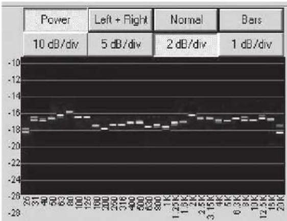
- Using the built-in Slit EQ Analyzer, run a pink noise test fi lm (Cat 69P or equivalent). Adjust the focus of the soundhead optics for the best high frequency response on the analyzer (see below). At the same time, adjust the azimuth for the thinnest display on the oscilloscope. The focus and az muth adjustments interact, so it will I necessary to keep adjusting both unt the best combination is achieved.
line
| Frequency | Power (dB) | |---|---| | 26 | 10 | | 31 | 10 | | 40 | 10 | | 50 | 10 | | 63 | 10 | | 80 | 10 | | 100 | 10 | | 125 | 10 | | 190 | 10 | | 200 | 10 | | 250 | 10 | | 316 | 10 | | 400 | 10 | | 500 | 10 | | 630 | 10 | | 800 | 10 | | 1K | 10 | | 1.25K | 10 | | 1.5K | 10 | | 2K | 10 | | 2.5K | 10 | | 3.15K | 10 | | 4K | 10 | | 5K | 10 | | 6.3K | 10 | | 9K | 10 | | 10K | 10 | | 12.5K | 10 | | 16K | 10 | | 20K | 10 | | Bars | Power (dB) | |---|---| | Power | 10 dB/div | | Left + Right | 5 dB/div | | Normal | 2 dB/div | | Bars | 1 dB/div |
- Using the built-in SLIT EQ Analyzer adjust the SLIT EQ slider until the response is flat to 12 kHz +/- 1 dB
8.3 Sum and Difference mode.
No Oscilloscope required.
When running a Cat 69P Pink Noise loop or the projector, precisely adjust the left and right projector gains so the red and green lines on the slit analyzer overlap.
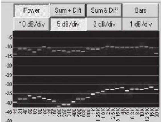
Click "Normal" on the Slit EQ Analyzer. The button designation changes to "Sum & Diff Adjust the projector sound head so the two graphs are roughly parallel.
line
| Frequency | Power (dB) | Sum + Diff (dB) | Sum & Diff (dB) | Bars (dB) | |---|---|---|---|---| | 25 | -45 | -10 | -10 | 1 | | 31 | -40 | -10 | -10 | 1 | | 40 | -35 | -10 | -10 | 1 | | 50 | -30 | -10 | -10 | 1 | | 63 | -25 | -10 | -10 | 1 | | 80 | -20 | -10 | -10 | 1 | | 100 | -15 | -10 | -10 | 1 | | 125 | -10 | -10 | -10 | 1 | | 160 | -5 | -10 | -10 | 1 | | 200 | 0 | -10 | -10 | 1 | | 250 | 5 | -10 | -10 | 1 | | 316 | 10 | -10 | -10 | 1 | | 400 | 15 | -10 | -10 | 1 | | 500 | 20 | -10 | -10 | 1 | | 630 | 25 | -10 | -10 | 1 | | 800 | 30 | -10 | -10 | 1 | | 1K | 35 | -10 | -10 | 1 | | 1.25K | 40 | -10 | -10 | 1 | | 1.8K | 45 | -10 | -10 | 1 | | 2K | 50 | -10 | -10 | 1 | | 2.5K | 55 | -10 | -10 | 1 | | 3.15K | 60 | -10 | -10 | 1 | | 4K | 65 | -10 | -10 | 1 | | 5K | 70 | -10 | -10 | 1 | | 6.3K | 75 | -10 | -10 | 1 | | 8K | 80 | -10 | -10 | 1 | | 10K | 85 | -10 | -10 | 1 | | 12.5K | 90 | -10 | -10 | 1 | | 16K | 95 | -10 | -10 | 1 | | 20K | 100 | -10 | -10 | 1 | Power: 10 dB/div; Sum + Diff: 5 dB/div; Sum & Diff: 2 dB/div; Bars: 1 dB/div.The top graph is controlled primarily by the focus of the reader. The bottom graph is controlled primarily by the azimuth.
First, the focus must be adjusted to achieve the best high frequency response for the top curve.
Most likely, the bottom graph will rise quickly at high frequencies. Carefully rotate the sound lens or reader until the curve is horizontal.
Note: It is a bit of a juggling act to keep rotating the reader and focusing it to achieve the best high frequency response on the top graph and the most horizont response on the bottom graph.
The graph below shows a reader with an azimuth error. The rising lower curve shows the phase difference between left and right channels. This is similar to a lissajous pattern on an oscilloscope where an ellipse indicates a poor alignment. The oscilloscope pattern is actually less accurate than the difference display. In the lissajous pattern, all the frequencies are added together so a phase difference at 20 kHz is less obvious. The difference display on the RTA shows the phase difference at each frequency

line
| Power | Sum + Diff | Sum & Diff | Bars | |---|---|---|---| | 10 dB/div | -40 | -10 | 1 dB/div | | 5 dB/div | -35 | -15 | 1 dB/div | | 2 dB/div | -30 | -20 | 1 dB/div | | 1 dB/div | -25 | -25 | 1 dB/div |8.4 Mono EQ and Bypass Level

line
| Frequency | Value | | --------- | --------- | | -10dB @8KHz | -10 dB | | -3dB @4KHz | -3 dB | | 32.0 | 32.0 | | 6.5 | 6.5 |- Click on the INPUT tab and select MONO format. Thread a pink noise loop on the projector. Using the SLIT EQ Analyzer, adjust the MONO EQ un the above curve is achieved.
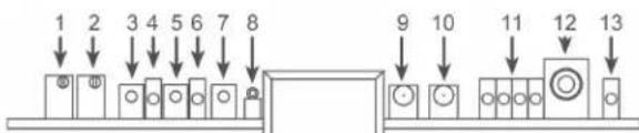
- Set the bypass level by adjusting trim-pot (1) until the voltage on the bypass level test point (8) reads 300 mV rms. Repeat the procedure for Projector 2 using trimpot (2). When the JSD-80 power switch is in the “off” position and the emergency backup power supply is present the main fader will control the bypass level.
8.5 Optical Surround Gain and Delay
- Click the INPUTS tab and thread a Dolby Cat 151 test film on the projector.
- Mute the screen channels and, using an RTA or SPL meter, adjust the SURR GAIN in the MATRIX CONTROLS so that the SPL level in the back matches the SPL level in the front. The SURR DELAY slider should be at 10 ms.
- Calculate the surround delay by using the following formula:
Length of theatre - (width of theatre/2) +20 = Delay in ms
- Set the SURR DELAY control accordingly.
8.6 Optical Subwoofer
See Section 9.5
8.7 Analog Non-Sync, AUX Levels, MIC Levels
- Set main fader to 7.0. Connect the sound source to the NON-SYNC L and R RCA jacks. Click on the INPUTS tab. Select the NON-SYNC format. Adjust the left slide pot and both channels will change. The master fader should be set at 7.0.
- Set main fader to 7.0. Connect the sound source to the AUX L and R RCA jacks. Click on the INPUTS tab. Select the AUX format. Use the main left and
right sliders outside the Preamp Calibration box to set the AUX level.
- Connect a microphone to the DB-9 connector (pins 1+ and 2- with shield on 5). If the microphone is an electret type that requires 5 to 9 V DC you ma use pin 7 on the DB-9 for that power (see Section 12). Click on the Inputs tab and select the MIC format. Adjust the left slide pot and both sides will change.

- Select the Formats tab and select Mic. Click the appropriate radio button to direct the Mic to center or surround channels.
8.8 Optional Digital Non/Sync, Digital Aux & Digital Eight-Channel inputs

Note: For these inputs to be active, the optional DI83 Module must be installed in the processor.
In the Format screen, select Non/Sync. "Input Type" will appear next to the format level slider. By selecting S/PDIF, a digital bit stream can be fed into the processor.
Note: The system supports either an analog or digital input for Non/Sync bu not both.
Typical input signals could be the digital coax output of a CD player, the digital coax output of a DVD player or a computer sour card. These outputs are typically "Orange" RCA jacks.
The processor also supports a S/PDIF Input in the Aux format.
Note: The system supports either an analog or digital input for Aux but not both.
When selecting S/PDIF, the Digital Delay be will appear below "Input Type." Since there is only one digital delay for AES/EBU, and S/PDIF inputs, setting this will affect all three digital inputs; (Ext 2, Non/Sync and Aux), the range is 0-100 ms input delay, 0-127 ms SURR delay.
The processor will accept stereo or AC3 data and decode 5.1 channels. The processor does not support DTS consumer bitstreams.
As with the AES/EBU input, if a fault occurs in the S/PDIF bitstream, the processor will mute. There are no emergency fallback formats for the S/PDIF inputs.
Note: For the AES/EBU inputs to be active, the optional AES/EBU module, DI83 must be installed in the processor.
The "EXT 2" digital domain input is configured for eight channels (four differential AES3 PCM data pairs with any sample rate from 32 to 96kHz ) See Section 12 for connector pinout specifications
Any AES3 PCM channel format ID bits (such as Pro/Consumer, Pre Emphasis, etc.) are ignored. If there is a fault in the AES/EBU data stream, the system reverts to a pre-selected emergency mode. This will occur if the AES/EBU word clock is lost or if the processor detects “non PCM” Data.
The DI83 module in this processor, which decodes Dolby® Digital bitstreams, is not intended for 35mm fi lm. The DI83 is intended for alternative content only.

To set the emergency digital fall back screen on the laptop interface, select "EXT 2" format. A box labelled "Digital Fallback" will appear. Simply select the emergency format desired. Selecting "EXT 2" will keep the processor in that format even though the audit may be muted. When the AES/EBU data is restored, the system will un-mute and continue to operate in the "EXT 2" format.
8.9 Digital Time Delays
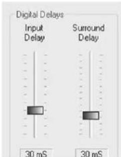
When “EXT 2” is selected, a box labelled “Digital Delay” will appear. The “Input Delay” slider controls the overall time delay required to compensate for various video projectors. For example, a typical DLP projector requires about 80 ms delay. Consult your video projector manual for the exact delay required. The second slider controls the delay for the surround channels. The surround delay should be set by the following formula:
Length of theatre - (width of theatre/2) + 20 = Delay (in ms)
Note: After you are satisfied with the A Chain settings, you will want to save them to the unit. Refer to Section 9.5 for details.
Note: When the computer is connected to and controlling the JSD-80, the front panel controls will not function, with the exception of the Mute button.
9.1 Channel Confi guration
Selecting "File" in the menu bar will produce a drop down box. Click on "Input Configuration".

The processor supports either fi ve screen channels or "Ex" back surround channels but not both.
Select the appropriate configuration and click "OK".
Note: This configuration will affect the equalizer and format panels.
9.2 Headroom Settings
Selecting "File" on the menu bar will produce a dropdown box. Click on "Headroon Adjustment".

Select one of the three settings. Generally, 26 dB of headroom is sufficient provided there is not more than 6 dB total boost between bass and low frequency 1/3 octave filters or between treble and high frequency 1/3 octave filters. For instance, if the bass slider is set at +3 dB and any of the 1/3 octave eq bands from 40-125 Hz are boosted more than 3 dB, the headroom will be compromised.
Selecting 29 dB headroom would allow a full 6 dB bass boost plus up to +3 dB boost in any of the 40-125 Hz bands.
In each case, it is the total boost that impacts the headroom. For 26 dB, the maximum boost is 6 dB; for 29 dB, the maximum boost is 9 dB; for 32 dB, the maximum boost is 12 dB.
9.3 Main Channels
Left, Center, Right, Left Surround, Right Surround, (Left Center, Right Center or Back Surround Left, Back Surround Right).
Before proceeding with the room equalization it is imperative that the loudspeaker and crossover systems be properly aligned. Issues like speaker phasing and horn tilt need to be checked. When using crossover the low, mid and high frequency drivers must be balanced to produce a relatively even response from 100 Hz to 5 kHz.
- Set up an external REAL TIME ANALYZER or the internal JSD-80 REAL TIME ANALYZER with the microphon two-thirds of the way back and one-third of the way in from the side of the auditorium. If a multiple microphone system is being used (such as the USI Inc. MMP-10), set up the microphones according to the instructions provide with that system. Set the MAIN FADEH to "7.0." Access the channel output controls on the Output panel on the JSD-80 Laptop Interface Software.
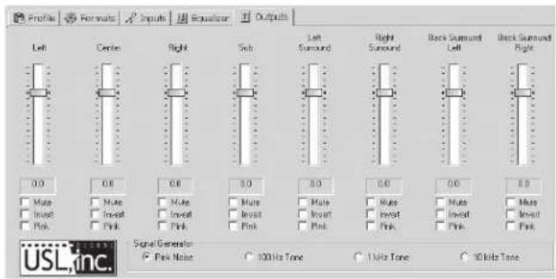
When aligning the auditorium for the first time with the JSD-80 Laptop Inte face Software, it is recommended to set all the channel gains to minimum, click the "Pink Noise" radio button in the Signal Generator box, click the "Pink" checkbox under the left channel slider, then exit the Output Screen to the Equalizer Screen for the frequency alignment.
Note: When using the generator, the default mode allows one active channel at a time. Holding down the control key allows selection of multiple channels fo
the generator (e.g., center and subwoof channels).
To use the internal JSD-80 REAL TIME ANALYZER, connect the microphone to the MIC input on the JSD-80. (See Section 12 for connector pin-outs.) With the pink noise generator turned on and the equalizer screen displayed on the laptop select the inputs screen. Note that the MIC input is selected. The auditorium microphone can be adjusted by using the MIC gain slider. Double click on the REAL TIME ANALYZER screen. A new window will open. Slide the window to the bottom of the laptop screen. Now select the equalizer tab and move the screen about the REAL TIME ANALYZER display
- Slowly raise the level of the left channel power amplifier to its full on position. Now, slowly raise the gain slider until the SPL Meter indicates approximate 85 dB SPL (82 dB SPL for the surround channels).

line
| FREQ | dB | |-------|-----| | 50Hz | -1 | | 2kHz | 0 | | 4kHz | -3 | | 8kHz | -6 | | 16kHz | -10 |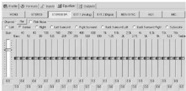
- Adjust the equalizer sliders until the response shown is obtained. Please note that once a slider is selected with a mouse click, the cursor pad up/dow keys will adjust the slider. The left/right keys will select the adjacent 1/3 octave slider. Use the bass and treble sliders to achieve the overall shape of the auditorium response. After making the
EQ adjustments, it may be necessary to fi ne-tune the output level setting

- Repeat the tuning procedure for the center, right and additional channels. The JSD-80 includes a copy feature that minimizes the time required for this.
After equalizing the left channel, copy these settings to the center and right channels. Since all three front speakers are usually similar, if not identical, the EQ settings will be a close starting point. Similarly, after equalizing the left surround, copy these settings to the right surround channel
9.4 Subwoofer Channel
There are three separate subwoofer signal in the JSD-80. One subwoofer signal is created by summing the LT and RT channels on the two-channel input card. This signal has its own adjustable low pass fi lter and +/- 6 dB gain trim. The second subwoofer signal is a discrete input on the analog eig channel connector. The third subwoofer signal is a discrete input on one of the digi AES-EBU pairs. All the above signals pass through the main subwoofer parametric equalizer and channel gain.
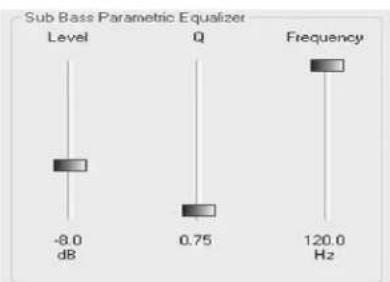
- Using the Equalizer Screen, select the Subwoofer channel radio button. Make sure the gain is set at the minimum, -22 dB. Slowly raise the power amplifier gain to maximum. Raise the channel gain slider on the JSD-80 software until the Subwoofer signal reaches roughly the same point as the center channel on the RTA.
bar
Sub Bass Parametric Equalizer | Category | Sub Bass Parametric Equalizer (dB) | Frequency (Hz) | |---|---|---| | Level | -8.0 | 120.0 | | Q | 0.75 | 0.75 | | Frequency | 0.75 | 0.75 |- Study the Subwoofer response on the RTA. The parametric will allow you to smooth the dips or take out bumps in the response from 20 to 100Hz . Adjust the FREQ slider to the same frequency as the peak. Set the Q control to about 4. Adjust the equalizer gain until response becomes flatter at the selective frequency. Adjust the Q control to widen the effect of the equalizer to achieve the best, fl attest response. It may be necessary to slightly readjust all the three controls until the best results are achieved.
line
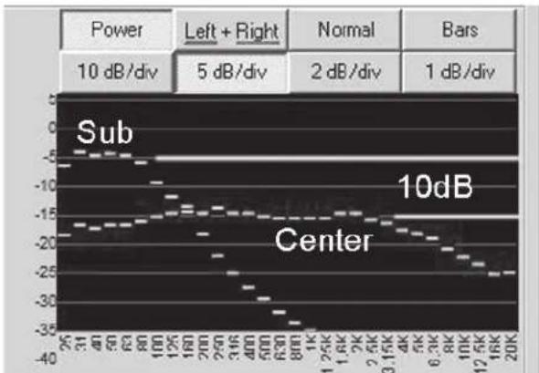
| Frequency | Sub Power | Center Power | | --------- | --------- | ------------ | | 100K | -15 | -25 | | 150K | -10 | -30 | | 200K | -5 | -35 |- Select the output screen and select both the center and subwoofer pink noise by holding down the "Ctrl" key and checking the boxes. The subwoofer should fill in the lowest frequency and create a smooth overall response on the RTA from 25 Hz to 1 kHz. It may be necessary to adjust the subwoofer channel gain. It also may be necessary to click to phase invert on the subwoofer to be sure that the low frequencies of the center and subwoofer are adding rather than subtracting. Set the final subwoofer level so that its horizontal display (20-100 Hz) is
10 dB ABOVE the horizontal display of the center channel on the REAL TIME ANALYZER.
9.5 Optical Subwoofer
- Once the subwoofer channel is equalized and the level set, it is time to trim the optical subwoofer parameters.
- Turn off the pink noise generator.
- Thread a pink noise loop Cat 69 P or equivalent on the projector and select mono.
- Set the optical subwoofer frequency to 50 or 60 Hz.
- Using the auditorium microphone not the level of the pink noise from the center channel.
- Adjust the optical subwoofer gain so the subwoofer output is on the same horizontal line as the center channel on the REAL TIME ANALYZER.
9.6 Saving Settings After Alignment
After completing the alignment, the configuration you have setup should be saved to the onboard DSP Flash RAM. To do this, choose the Disconnect icon from the toolbar or Disconnect from the Communication menu.

You will be prompted with the following screen providing several save options.

Clicking "Yes" will save your current settings to the JSD-80 and then verify that the were correctly saved to the unit. Choosing "No" will keep you connected to the JSD-80
unit allowing you to make more modifi ca- tions if needed. Choosing “Do Not Save” will disconnect from the unit and disregard all changes made for the current session. The unit will continue to retain the current settings until power is removed then the previous confi guration will be used
Checking the “Save to Personality Module” will save a backup of the entire unit configuration to the unit’s Personality Module. The personality module will provide a backup restore option in case of catastrophic processor failure. Make sure a Personality Module is present in the JSD-80.
Note: It is essential that when writing to the Personality Module, the Write Protect Switch is in the "OFF" (left) positio. Once the parameters are saved, however it is equally important that the switch b returned to the "ON" position.
Having a backup copy of all settings in the Personality Module permits loading a copy of all settings into a new replacement module without the need for a computer an technician.
10.1 Preset Format Levels
Click on the FORMATS tab. Select the form of interest. Adjust the "Format Level" on the panel to an appropriate setting.
Note: When changing levels in EXT 1 or EXT 2, remember to also change the Stereo SR level the same amount.
10.2 Startup Mode
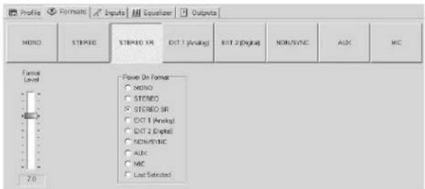
Select the default startup mode from the li shown. Selecting NON-SYNC will cause the unit to "wake up" in non-sync every time it is powered up. Choosing "Last Selected" w cause the unit to resume its last operation format before it was powered down.
10.3 Remote Fader

- The remote fader function can be accomplished with a simple pair of normally open switches. One button increases levels, the other decreases levels. The LED display on the JSD will indicate the change in discrete steps limited to 4.0 - 9.0.
10.4 System Restore

- In the event of a catastrophic system failure, you may install the last con-
figuration saved to the Personality Module (1). If the control card is the module that has failed you will need to remove the Personality Module from it and insert it into the replacement control card from USL. If the input or output card has failed, you simply need to replace the failed one with a new module from USL. Once the replacement module is installed, you will hold down the restore button (4) as you power up the system. Hold the restore button until the "Restore" LED (5) begins to flash. Within thirty seconds, the "Restore" LED (5) stops flashing, the system is restored. Turn off the unit, wait 60 seconds and turn it back on. This procedure will restore the system without the need for a lap top or technician.
⚠️ Note: If you are replacing the contro module as a part of the repair process, remember to remove the Personality Module from the defective card and insert it into the replacement control module.
10.5 Format Options
This feature allows the technician to change some of the Format button/automation functions. By clicking on the Format Options box on the Formats tab on Laptop Interface Software the options are displayed for each of the Format selections.

The MONO, STEREO A, STEREO SR button can be configured with the following noise reduction options: "None," A Type, SR Type. The same buttons can also be configured with the following matrix decoding options: "5.1 Stereo," "2.0 Stereo," or "Mono." The 5 stereo option is the default setting. The 2.0 stereo option is for either Left/Right stereo or Center/Surround systems.

The EXT 2 button can be configured either for "AES-EBU" (Digital) or "Analog" inputs.
10.6 Wiring for an Electret Microphone
An Electret microphone can be connected to the JSD-80 using a DB-9 male plug as shown below.
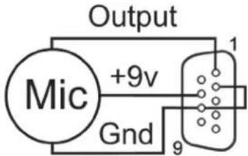
Section 11: Troubleshooting
| PROBLEM | CHECK | SOLUTION |
| SOUND SYSTEM DOES NOT WORK and no LEDs are lit on the Front Panel. | Power source | Reset circuit breaker or replace fuse. |
| Power cord | Make sure power cord is firmly seated. | |
| Power supply fuse | Replace Fuse - SLO BLO 500 mA, 250 V | |
| SOUND SYSTEM DOES NOT WORK and +5 V and +/-12 V LEDs on the Front Panel are lit. | Power amplifiers | Make sure amplifiers are operating and volume controls are up. |
| Change-over | Switch change-over to operating projector. LED lights on the Input Module indicate which projector is in use. | |
| Exciter lamp | Replace bulb or repair exciter supply. | |
| Stereo solar cell on projector | Make sure the solar cell is illuminated and clean. Use compressed air. DO NOT USE ORGANIC SOLVENTS OR ALCOHOL. | |
| Note: the Backup Power LED should be lit to indicate operation of the Backup Supply | LED indicators on the INPUT and OUTPUT modules | Make sure the Input Module's indicator LEDs are flickering with program material. If not, there is a problem with the solar cell, the wiring, or the Preamp. If indicator LEDs are flickering, the problem is most likely the unit wiring, the power amplifiers, or the loudspeakers. |
| Turn off main power switch to put unit in BYPASS mode. Note: This mode puts sound in all three front channels. | If sound comes out of the three front speakers, then the problem is in the JSD unit. If there is no sound, the problem is somewhere else. | |
| NO SOUND IN ONE OR MORE FRONT CHANNELS | Turn off main power switch to put unit in BYPASS MODE. | If the channel or channels are still dead, the problem is an amplifier, speaker, or wiring. If all front channels work, then the problem is in the JSD unit. |
| Press other Format switches. | Check different formats to determine if only one format has a problem. Refer to later section in TROUBLESHOOTING. | |
| NO SOUND IN SURROUND CHANNEL | Power amplifier | Replace speaker fuse or main fuse. Replace amplifier er. |
| Speakers or wiring | Speakers are often series-connected, so if one fails they all will not work. | |
| If NON/SYNC MUSIC plays but the STEREO does not, there is a problem in the soundhead wiring. | ||
| SOUND IS DISTORTED | Power amplifi er or speakerPress several format buttonsTry NON/SYNC MUSICSTEREO modeExciter lamp | Try to determine if distortion is in one or all channels. If distortion is one channel, exchange power amplifi ers or speaker lines to locate problem.Try to determine if one or all formats are distorted.If MUSIC is not distorted, the problem is in the input module or the SOLAR CELL alignment.If there is distortion only in this mode then there could be a problem in the input module.Make sure correct lamp is used. There are vertical and horizontal versions of many exciter lamps. Soundhead misalignment can cause distortion. |
| HUM IN ALL CHANNELS | Stray light pickup at the solar cell on the projectorPREAMP ModuleWiring between the processor and power amplifi ers | Eliminate source of stray light.Eliminate cause of hum ground loops, bad exciter lamp supply, JSD unit located too near hum fi eld from power amplifi er or another piece of equipment. |
| BUZZING SOUND IN ALL CHANNELS, MAINLYTHE SURROUNDS | INPUT module | The Input may have some high frequency oscillation. Check the Solar Cell wiring. Make certain that the lines are not routed too close to the Power Amplifi er or Loudspeaker wiring. It may be necessary to re-route the cell lines. If in doubt remove wires from the backboard and short the input. If this does not solve the problem, replace the Input module. |
| STEREO MODE- SOUND FROM LEFT OR RIGHT CHANNEL ONLY | LED indicators on INPUT module | If only the left or right LED indicator is lit with program material, check the projector wiring and input module. |
| STEREO MODEDIALOG IS LEAKINGINTO THESURROUNDS | Soundhead azimuthalignment and/orpreamp level andhigh frequency boostsettings | Re-adjust soundhead azimuth and resetpreamp levels and high frequency boost withtest fi lm. |
| Soundhead guiderollers | Make sure the soundhead guide rollers arenot loose and do not have any end play.Some rollers are spring-loaded on one side.Make sure the fi xed side is not loose. | |
| Output module | Surround levels are set too high. Reset SPLlevels. | |
| STEREO MODESURROUNDS AREEXTREMELY LOW | Soundhead alignment | The solar cell is too far back. Move it to within .040" (1 mm) of the fi lm and readjust. |
| BUZZING IN SYSTEMWHEN CONNECTINGLAPTOP | Computer PowerPack | Lift power ground on Computer power packor run computer on battery power. |
| EXT 2 LED FLASHES | Connection ofExternal AES-EBUdevice | When the Word Clock is missing on theLeft/Right channel pair, the front LED willfl ash, indicating a fault of the external device.It will also fl ash if there is no external deviceconnected to EXT 2. Check the wiring andfunctionality of the external device. |
| ALL THE FORMATBUTTON LEDSFLASH AND NUM-BERS APPEAR INTHE MAIN FADERDISPLAY | Make sure all cardsare fi rmly seated. | Make a note of the numbers that appearin the main fader display. Put the unit intoBYPASS to prevent possible loudspeakerdamage. The fl ashing LEDs mean thatsoftware corruption has been detected. A“91,” “92,” or “93” is a software fault in theInput Module (JSDA80). A “61,” “62,” or“63” is a software fault in the Output Module(JSDO80). Have the technician replace thedefective module and follow the SystemRestore in Section 10.4. |
Connector Pinouts
RS232 (DB-9F)
- Reserved
- TXD Transmit Data
- RXD Receive Data
- Reserved
- Signal Ground
- Reserved
- CTS Clear To Send
- RTS Request To Send
- +5 V for Bluetooth Adaptor
Automation (DB-25F)
- Mono pulse
- Stereo pulse - A Type
- Stereo pulse SR
- Aux pulse
- External 1 - Analog
- External 2 - AES/EBU
- Non-Sync pulse
- Mic pulse
- Reserved
- Mute Pulse
- Reserved
- Automation Return
- +5 V DC
- Mono LED
- Stereo A LED
- Stereo SR LED
- Aux LED
- Extl. 1 LED - Analog
- Ext. 2 LED - AES/EBU
- Non-Sync LED
- Mic LED
- Reserved
- Mute LED
- Reserved
- Projector Changeover
Monitor Output (DB-25M)
- Chassis Gnd
- Out L +
- Out LC -
- Chassis Gnd
- Out C +
- Out RC -
- Chassis Gnd
- Out R +
- Chassis Gnd
- Out LS -
- Out RS -
- Out SW -
- Chassis Gnd
- Out L
- Chassis Gnd
- Out LC +
- Out C-
- Chassis Gnd
- Out RC +
- Out R -
- N/C
- Chassis Gnd
- Out LS +
- Out RS +
- Out SW +
- Analog Gnd
- In Rs
- Analog Gnd
- Analog Gnd
- Analog Gnd
- Analog Gnd
- Analog Gnd
- Analog Gnd
- Analog Gnd
- Analog Gnd
- Analog Gnd
- Analog Gnd
- Analog Gnd
- Analog Gnd
- In L
- In Ls
- In Rc
- In R
- In Lc
- Analog Gnd
- In C
- Reserved
- Analog Gnd
- Analog Gnd
- In SW
- N/C
Ext 1 - Analog (DB-25F)
Ext 2 AES/EBU (DB-25F)
- L/R/ Return
- L/R -
- C/SW +
- C/SW Return
- Ls/Rs
- Lc/Rc +
- Chassis Gnd
- N/C
- Chassis Gnd
- N/C
- N/C
- Chassis Gnd
- N/C
- L/R +
- Ls/Rs Return
- C/SW -
- Ls/Rs +
- Lc/Rc Return
- Lc/Rc -
- Chassis Gnd
- N/C
- N/C
- Chassis Gnd
- N/C
- N/C
- In L+
- In L-
- Chassis Gnd
- In R+
- In R-
- Analog Gnd
- Reserved
- Reserved
- Analog Gnd
- Mic in +
- Mic in
- Reserved
- Reserved
- Chassis Gnd.
- N/C
- 9 V
- Analog Gnd.
- N/C
Projector Inputs (DB-9F)
Mic Inputs (DB-9F)
B CHAIN ALIGNMENT
- Select Lc/Rc or Bsl/Bsr channel operating mode in the File menu of the Interface Software.
- Set Headroom (26 dB is normal). Olde speaker systems may require 29 dB.
3 Equalize front channels and set SPL levels (85 dB) using the Equalizer screen.
4 Equalize surround channels and set SPL levels (82 dB) using the Equalizer screen.
5 Equalize subwoofer channel and set level 10 dB above the horizontal center channel display on a Real Time Analyzer measuring the auditorium.
A CHAIN ALIGNMENT-Projectors
1 Set Projector levels using 35mm 50% tone fi lm Use the Inputs screen on th Interface Software.
2 Set BYPASS levels using 35mm 50% tone fi lm (measure 300 mv at test poi 8).
3. Set Projector high frequency response with 35mm pink noise fi lm
4. Set MONO high frequency response with 35mm pink noise fi lm
5. Set SUBWOOFER level and frequency with 35mm pink noise fi lm (the subwoofer level in MONO should line up horizontally with the center channel display on the RTA measuring the auditorium).
6. Set SURROUND level with 35mm front, back pink noise fi lm
7. Set SURROUND delay based upon auditorium size.
A CHAIN ALIGNMENT-Other inputs
- Set Non-Sync level on the Inputs screen of the Interface Software or select Non Sync S/PDIF
- Set Aux level or select AUX S/PDIF on the Inputs screen.
- Set Mic level on the Inputs screen.
- Set EXT 2 and S/PDIF main and surround delays for a video projector on the Formats screen.
- Set EXT 2 fallback format on the Formats screen.
- Set Mic center or surround position of the Formats screen.
FINAL SETTINGS
- Set all FORMAT levels on Formats screen of the Interface Software.
- Set Startup format on the Formats screen.
- Test Remote Volume panel if one is installed.
- Save settings to a file on the compute running the Interface Software.
- Save settings to the JSD-80.
- Turn off the Write Protect Switch and save setting to the Personality Modul in the JSD-80. Turn on the Write Protect Switch.
- Cinema Sound Processor
- Introduction ...... 3
- Installation 9
- Block Diagrams ..... 10
- System Modules ...... 14
- Front Panel 15
- Back Panel 16
- JSD-80 Interface Software ..... 19
- "A" Chain Alignment 23
- "B" Chain Alignment 29
- Other Options 33
- Trouble Shooting 35
- Connector Pinouts ...... 38
- Installation Check List ...... 39
- One Year Limited Warrant
- Safety Notices
- To Avoid Fire and Personal Injury
- Safety Standard
- The JSD-80 Overview
- IMPORTANT NOTICE
- Technical Specifications
- Signal Connections
- Signal Inputs
- Line Outputs:
- Audio Signal Paths
- Automation Inputs:
- Automation Outputs (DB25):
- Power Input
- Declaration of Conformance, CE
- Certifications
- Equipment Class
- System Hardware Mounting and Grounding
- System Cooling and Ventilation
- Important
- Section 3: Block Diagrams
- 3.4
- Control Block
- Diagram
- Input Module
- Output Module
- Control Module
- Overview
- Adjusting Format Levels
- Adjusting Projector Gains
- Rear Wiring Diagram
- Back Panel Input Connections
- Projector Inputs
- Non-Sync Inputs - Analog
- Auxiliary Input - Analog
- Microphone Input
- EXT 1 (Analog)
- EXT 2 (Digital)
- Non/Sync Inputs - Digital
- Auxiliary Inputs - Digital
- Back Panel Signal Output Connections
- Main Outputs
- Monitor Outputs
- Hearing Impaired Output
- Automation Inputs (Phoenix Connector)
- Automation (DB-25)
- Note: An adapter is available to convert to the DTS automation pinout (DTS-6D).
- Bypass Power Input
- Remote Fader Input
- Changeover
- RS232 Port
- Installation Procedure
- The Opening Screen
- Profi le Screen
- Formats Screen.
- Inputs Screen.
- Equalizer Screen.
- Outputs Screen.
- Slit EQ Analyzer Screen
- Creating, Saving and Loading Configuration Files
- Disconnected
- Connected
- Section 8. "A" Chain Alignment
- Preparing The Sound Head
- Alignment of Solar Cell and Preamplifi e
- Sum and Difference mode.
- Mono EQ and Bypass Level
- Optical Surround Gain and Delay
- Optical Subwoofer
- Analog Non-Sync, AUX Levels, MIC Levels
- Optional Digital Non/Sync, Digital Aux & Digital Eight-Channel inputs
- Note: The system supports either an analog or digital input for Aux but not both.
- Note: For the AES/EBU inputs to be active, the optional AES/EBU module, DI83 must be installed in the processor.
- Digital Time Delays
- Channel Confi guration
- Headroom Settings
- Main Channels
- Subwoofer Channel
- Optical Subwoofer
- Saving Settings After Alignment
- Preset Format Levels
- Startup Mode
- Remote Fader
- System Restore
- Format Options
- Wiring for an Electret Microphone
- Connector Pinouts
- RS232 (DB-9F)
- Automation (DB-25F)
- Monitor Output (DB-25M)
- Ext 1 - Analog (DB-25F)
- Ext 2 AES/EBU (DB-25F)
- Projector Inputs (DB-9F)
- Mic Inputs (DB-9F)
- B CHAIN ALIGNMENT
- A CHAIN ALIGNMENT-Projectors
- A CHAIN ALIGNMENT-Other inputs
- FINAL SETTINGS
Brand : USL
Model : JSD-80
Category : Processeur audio cinéma