MMP-10 - Multiplexer USL - Free user manual and instructions
Find the device manual for free MMP-10 USL in PDF.


| Product Type | Microphone Multiplexer |
| Number of Microphone Channels | 4 |
| Microphone Type | Laboratory grade test microphones, calibrated with multiplexer |
| Calibration | Each microphone calibrated with its multiplexer; factory-adjusted individual trim potentiometers |
| Scan Modes | Individual microphone selection or sequential automatic scan |
| Scan Rate | Adjustable, 7 to 21 Hz |
| Output Level | Adjustable overall output level; factory set to 15mV (-36 dB) with 1k ohm load |
| Power Source | 9V battery (alkaline recommended) |
| Current Drain | Approx. 20 mA |
| Low Battery Indicator | Blinking red LED; unit resets to microphone 1 |
| Output Connector | 3-pin female XLR |
| Remote Control | Momentary in-line push button on audio cable; cycles through microphones and scan mode |
| Compatibility | Works with any audio spectrum analyzer; adapters available for various models |
| Included Accessories | Theater microphone seat mounts, adapter to 3-pin male XLR (MMP-ADS) |
| Construction | Rugged; small diameter lightweight umbilical cable |
| Warranty | 90 days from purchase new from authorized dealer; limited to repair or replacement |
| Approvals | Meets CE Approval Standards |
| Manufacturer | Ultra★Stereo Labs, Inc., San Luis Obispo, CA, USA |
Frequently Asked Questions - MMP-10 USL
User questions about MMP-10 USL
0 question about this device. Answer the ones you know or ask your own.
Ask a new question about this device
Download the instructions for your Multiplexer in PDF format for free! Find your manual MMP-10 - USL and take your electronic device back in hand. On this page are published all the documents necessary for the use of your device. MMP-10 by USL.
USER MANUAL MMP-10 USL
Ultra★Stereo Labs, Inc. warrants that the MMP-10 will be free from defects in material and workmanship under normal usage for a period of ninety (90) days after its purchase new from an authorized dealer. Our obligation under this warranty is limited to repairing or replacing any product or component which we are satisfied does not conform with the foregoing warranty and which is returned to our factory, freight paid, or serviced by one of our authorized contractors. The foregoing Warranty is exclusive and in lieu of all other warranties, whether expressed or implied. Such warranty shall not apply to any product or component (A) repaired or altered by anyone other than Ultra★Stereo Labs or an authorized service contractor; (B) tampered with or altered in any way or subjected to misuse, negligence or accident or (C) which has been improperly connected, installed or adjusted otherwise than in accordance with Ultra★Stereo Labs instruction. This warranty does not cover damage to surface finishes, normal wear, or failure resulting from abuse.
Table of Contents
Features 4
How It Works.... 5
Initial Calibration ...... 6
Setup Procedure 7
Microphone Placement 8
Microphone Mounting 9
Low Battery Indicator 9
Remote Switch Circuits 10
Specifications 11

Please record the following information for your records:
Model: ____ Serial Number: ____
Date of Purchase: ____ Purchased from: ____
MMP-10 Features
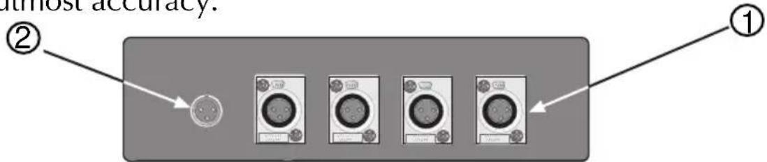
Four laboratory grade test microphones. ①
Each microphone is calibrated with its multiplexer to insure utmost accuracy.
(Top View)
Individual microphone selection or sequential scan.
Adjustable scan rate.
Blinking low battery indicator.
Overall output level adjust.
Works with any audio spectrum analyzer.
Small diameter, lightweight umbilical cable from the multiplexer to your analyzer.②
Theater microphone seat mounts included.
Rugged construction.

(Front View)
How It Works
The MMP-10 contains four high quality microphone preamplifiers, followed by an adjustable switching circuit. Microphone signals are routed through the unit in several different configurations.
On powerup, only microphone one is amplified and routed through the MMP-10 to your analyzer.
The remote switch at the analyzer end of the MMP-10 cable permits selection of other microphones. Pressing the switch once selects microphone two. Press it again and microphone three is selected; once more and microphone four is selected.
Pressing it once again starts automatic scan mode, which cycles through all four microphones, one at a time. Pressing it one more time resets the MMP-10 to microphone one.
Typical analyzer equipment is shipped with only a single microphone. The MMP-10 allows you to expand your equipment to four microphones. [Such multi-microphone measurement techniques achieve far superior acoustical results in auditoriums due to the averaging effect.]

MMP-10 Front

flowchart
graph TD
    A["Input"] --> B["Device 1"]
    A --> C["Device 2"]
    A --> D["Device 3"]
    A --> E["Device 4"]
    F["Output"] --> B
    F --> C
    F --> D
    F --> E
MMP-10 Top
Initial Calibration
The first time you use your new MMP-10, you should set the output level to match the single microphone supplied with your analyzer. To accomplish this find a suitable location and set up your analyzer with its own microphone.
Using pink noise through the sound system, adjust the amplifier level to produce a normal display (85 dbC). Next disconnect the analyzer microphone and connect the MMP-10 (with its four microphones) to the analyzer.
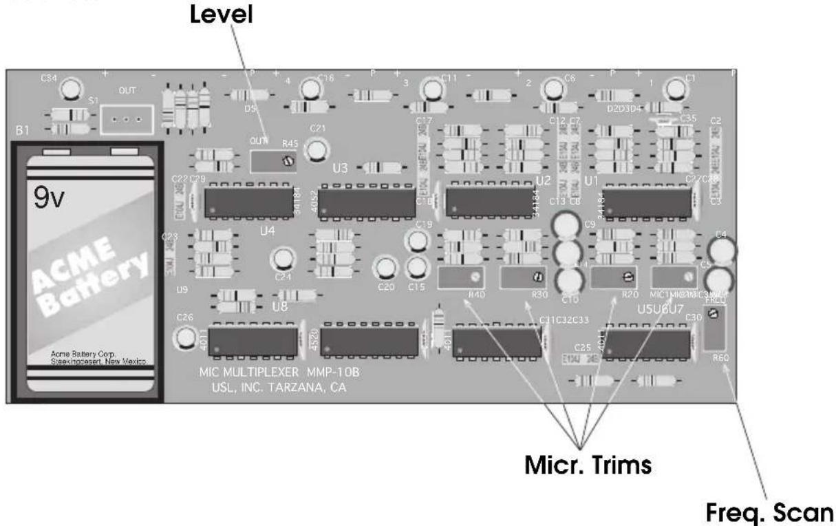
Open the MMP-10 back cover. Select microphone one and adjust the overall potentiometer R# 45 inside the MMP-10 to achieve the same level on your analyzer display as measured with the analyzer microphone. Verify that the remaining three microphones have the same reading.
(Note: it is not necessary to adjust individual trim potentiometers, R10, R20, R30, R40, as these are adjusted at the factory.)
Switch the MMP-10 to scan mode and observe the display of all four microphones. Different analyzers will integrate this switched signal in various ways. Adjust the scan rate potentiometer, R60, to achieve a smooth stable display. If the timing is too slow, the display will bounce.
Setup Procedure
Locate the MMP-10 approximately 2/3 back from the screen, off axis of the center speaker, usually between the center speaker and the right speaker to allow for viewing from the booth. Place microphone one at this position. Place the remaining mics. in a diamond pattern within the central area of the room. The microphones should be positioned horizontally with the microphone's screen facing up, toward the ceiling (Figure2). Insert the microphone connectors into the appropriate jacks on the MMP-10.
Connect the audio cable to the MMP-10 and switch the unit on. The red LED for microphone one will be on. Be sure to position the MMP-10 so you can view the LED display from the booth.
Plug the other end (i.e. momentary switch side) of the audio cable into your analyzer up in the projection booth. Switch on Pink Noise. Your MMP-10 wakes up with microphone one selected. Verify you have a signal from microphone one on your analyzer. Select microphone two, three then four to verify operation.
Select multiplex mode (indicated by the LEDs flashing in order: red, green, green green) and set your analyzer to the proper level and commence room equalization.
The multiplexer has been designed to allow for easy room averaging with a small but accurate four microphone multiplexer system. Room equalization using only one microphone is not recommended due to room modes. Using four microphones and MMP-10 multiplexer will allow for the best sound for the greatest number of seats in the room.
Remote control of the MMP-10 is achieved by using a momentary in-line push button located on the audio cable plugged into your analyzer. Pressing the button located on this cable cycles the MMP-10 through five states: Microphone 1, microphone 2, microphone 3, microphone 4 and multiplex (scan) mode.
Ideal Microphone Placement
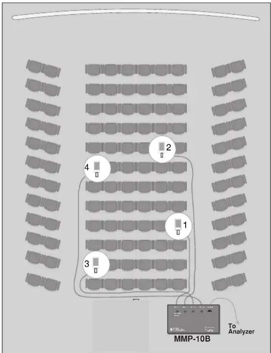
Figure 1
The microphones should be placed in the listening environment as shown above (Figure 1). Variations may apply depending upon size and shape of the auditorium but a diamond formation is best for overall sound field measurement.
Mounting the Microphone
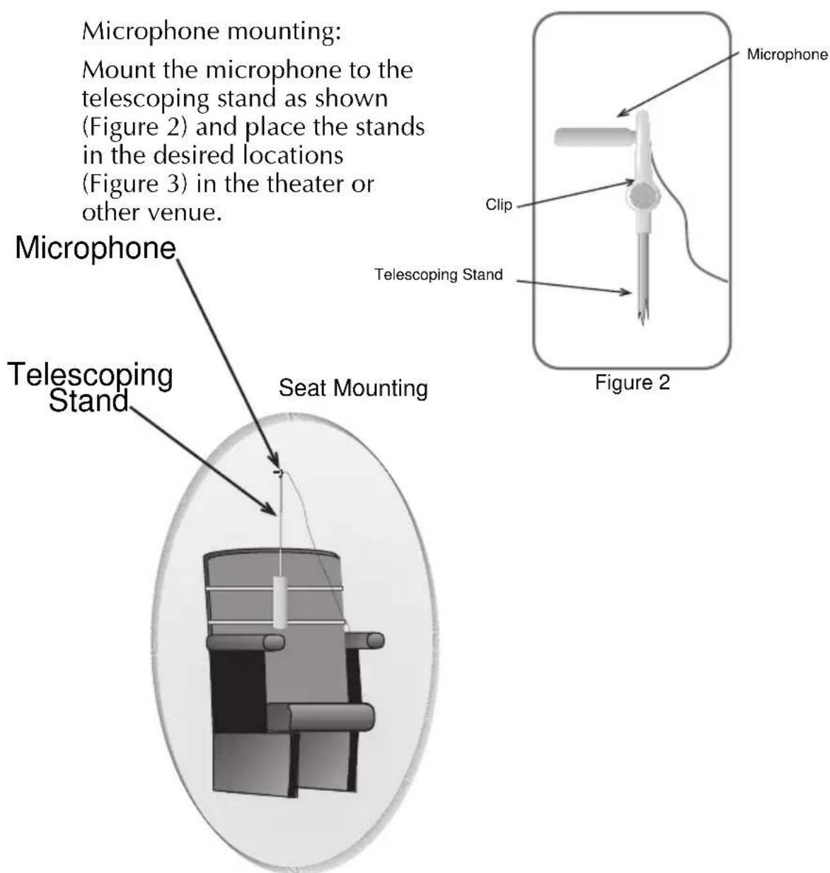
Figure 3
Low Battery Indicator
Low battery voltage can cause the unit to not switch properly, and may cause measurement errors. To avoid this, the MMP-10 incorporates a low battery sensing circuit. When the battery voltage drops too low, the unit will reset to microphone one, and the red LED will blink. Replace the battery with a standard 9V alkaline battery.
Remote Switch Circuits
A 3-pin female cord plug with a momentary on/off switch is a standard item in the MMP-10S kit. This switch cord will work with most balanced input analyzers.
3 PIN SWITCH CIRCUIT
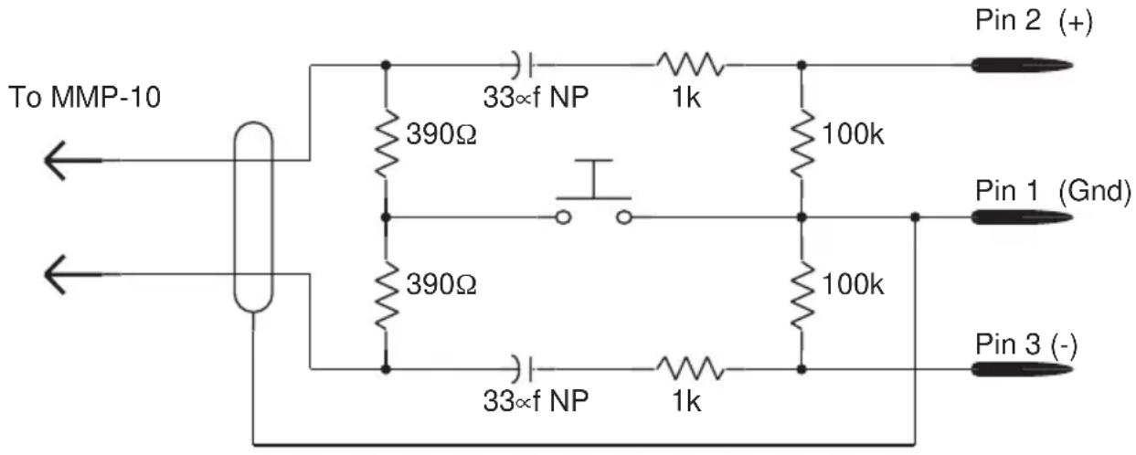
MMP Adapters
The MMP-10 output is a 3-pin female XLR connector. Included is an adapter to a 3-pin male XLR connector (MMP-ADS). Other adapters are available to convert to almost any analyzer or sound processor:
| Model # | Connector Type | For Use With |
| MMP-ADS | 3-pin XLR (male) | Audio Control, Gold Line, Abacus ARTA-160, Clark Techniq, HP-8050 |
| MMP-AD1 | 6-pin XLR (female) | Ivie 30, Ivie PC-40 |
| MMP-AD2 | 3-pin Mini-XLR (male) | Abacus ARTA-80 |
| MMP-AD5 | 1/8" Stereo Phone Plug | Dolby CP-500 |
Specifications
(1K ohm load on each leg of the balanced output)
Nominal microphone input level: -54 dB (2mv)
Maximum output level: -27 dBV (43mV) adjustable
Output impedance: 2K ohms
Number of microphone channels: 4
Individual microphone channel adjustment range: 9dB
Microphone scan rate: 7 to 21 Hz adjustable
Power source: 9 volt battery
Current drain: Approx. 20 ma.
Meets CE Approval Standards
Factory Settings
(1K ohm load on each leg of the balanced output)
Output level: 15mV (-36 dB)
Microphone scan rate: 10Hz
Ultra★Stereo Labs, Inc.
181 Bonetti Drive
San Luis Obispo, CA 93401 USA
Telephone 805.549.0161
FAX 805.549.0163
e-mail usl@uslinc.com

USL,Inc.
Quality Cinema Products
© 1996, 1998 Ultra★Stereo Labs, Inc.
San Luis Obispo, CA, USA.
All Rights Reserved
Brand : USL
Model : MMP-10
Category : Multiplexer