
TIF-4000 - Telecommunication Equipment RTS - Free user manual and instructions
Find the device manual for free TIF-4000 RTS in PDF.


| Product Type | Digital Thermometer/Hygrometer |
| Model | TIF-4000 |
| Brand | RTS |
| Measurement Range (Temperature) | -10°C to 50°C (14°F to 122°F) |
| Measurement Range (Humidity) | 20% to 90% RH |
| Accuracy (Temperature) | ±1°C (±1.8°F) |
| Accuracy (Humidity) | ±5% RH |
| Display | LCD screen with backlight |
| Power Supply | 2x AAA batteries (1.5V) |
| Battery Life | Up to 12 months |
| Auto Power Off | Yes, after 10 minutes of inactivity |
| Dimensions | 10.5 x 2.5 x 1.5 cm |
| Weight | 45 g (including batteries) |
| Material | ABS plastic |
| Warranty | 1 year |
| Certifications | CE, RoHS |
Frequently Asked Questions - TIF-4000 RTS
User questions about TIF-4000 RTS
0 question about this device. Answer the ones you know or ask your own.
Ask a new question about this device
Download the instructions for your Telecommunication Equipment in PDF format for free! Find your manual TIF-4000 - RTS and take your electronic device back in hand. On this page are published all the documents necessary for the use of your device. TIF-4000 by RTS.
USER MANUAL TIF-4000 RTS
Digital Hybrid Telephone Line
PROPRIETARY NOTICE
The product information and design disclosed herein were originated by and are the property of Bosch Security Systems, Inc. Bosch reserves all patent, proprietary design, manufacturing, reproduction, use and sales rights thereto, and to any article disclosed therein, except to the extent rights are expressly granted to others.
COPYRIGHT NOTICE
Copyright 2013 by Bosch Security Systems, Inc. All rights reserved. Reproduction, in whole or in part, without prior written permission from Bosch is prohibited.
*All other trademarks are property of their respective owners.
WARRANTY AND SERVICE INFORMATION
For warranty and service information, refer to the appropriate web site below:
RTS Intercoms ...... www.rtsintercoms.com/warranty
RTS Digital
RTSTW
AudioCom
RadioCom
Intercom Headsets......www.telex.com
CUSTOMER SUPPORT
Technical questions should be directed to:
Customer Service Department
Bosch Security Systems, Inc.
www.telex.com
TECHNICAL QUESTIONS EMEA
Bosch Security Systems Technical Support EMEA
http://www.rtsintercoms.com/contact_main.php
DISCLAIMER
The manufacturer of the equipment described herein makes no expressed or implied warranty with respect to anything contained in this manual and shall not be held liable for any implied warranties of fitness for a particular application or for any indirect, special, or consequential damages. The information contained herein is subject to change without prior notice and shall not be construed as an expressed or implied commitment on the part of the manufacturer.
| CAUTIONRISK OF ELECTRIC SHOCKDO NOT OPENCAUTION: TO REDUCE THE RISK OF ELECTRIC SHOCK, DO NOT REMOVE COVER. NO USER-SERVICABLE PARTS INSIDE. REFER SERVICING TO QUALIFIED SERVICE PERSONNEL. | THE EXCLAMATION POINT WITHIN THE TRIANGLE IS A WARNING SIGN ALERTING YOU OF IMPORTANT INSTRUCTIONS ACCOMPANYING THE PRODUCT. | |
| SEE MARKING ON BOTTOM/BACK OF PRODUCT. | ||
WARNING: APPARATUS SHALL NOT BE EXPOSED TO DRIPPING OR SPLASHING AND NO OBJECTS FILLED WITH LIQUIDS, SUCH AS VASES, SHALL BE PLACED ON THE APPARATUS.
WARNING: THE MAIN POWER PLUG MUST REMAIN READILY OPERABLE.
CAUTION: TO REDUCE THE RISK OF ELECTRIC SHOCK, GROUNDING OF THE CENTER PIN OF THIS PLUG MUST BE MAINTAINED.
WARNING: TO REDUCE THE RISK OF FIRE OR ELECTRIC SHOCK, DO NOT EXPOSE THIS APPRATUS TO RAIN OR MOISTURE.
WARNING: TO PREVENT INJURY, THIS APPARATUS MUST BE SECURELY ATTACHED TO THE FLOOR/WALL/RACK IN ACCORDANCE WITH THE INSTALLATION INSTRUCTIONS.
| ~ | This product is AC only. |
| CE |
Important Safety Instructions
- Read these instructions.
- Keep these instructions.
- Heed all warnings.
- Follow all instructions.
- Do not use this apparatus near water.
-
Clean only with dry cloth.
-
Do not block any ventilation openings. Install in accordance with the manufacturer's instructions.
-
Do not install near any heat sources such as radiators, heat registers, stoves, or other apparatus (including amplifiers) that produce heat.
-
Do not defeat the safety purpose of the polarized or grounding-type plug. A polarized plug has two blades with one wider than the other. A grounding type plug has two blades and a third grounding prong. The wide blade or the third prong are provided for your safety. If the provided plug does not fit into your outlet, consult an electrician for replacement of the obsolete outlet.
-
Protect the power cord from being walked on or pinched particularly at plugs, convenience receptacles, and the point where they exit from the apparatus.
-
Only use attachments/accessories specified by the manufacturer.
-
Use only with the cart, stand, tripod, bracket, or table specified by the manufacturer, or sold with the apparatus. When a cart is used, use caution when moving the cart/apparatus combination to avoid injury from tip-over.
-
Unplug this apparatus during lightning storms or when unused for long periods of time.
-
Refer all servicing to qualified service personnel. Servicing is required when the apparatus has been damaged in any way, such as power-supply cord or plug is damaged, liquid has been spilled or objects have fallen into the apparatus, the apparatus has been exposed to rain or moisture, does not operate normally, or has been dropped.
Table
of
Contents
INTRODUCTION 3
Introduction ....3
Description ....3
Specifications 5
Reference Views 6
INSTALLATION 9
DIP Switch Settings 9
DIP Switch (S201) Settings 9
Auto-answer (Switch 1) 9
Generate Ring Signal (Switch 2) 9
Password Required (Switch 3) 10
Intercom Port Address (Switches 4-7) 10
Full Duplex Method Switch 8 (S201) 12
Internal DIP Switch (S202) 13
Ring Count 13
DTMF Or Pulse Dial Selection 13
Point-to-point Seize 13
One Touch Dial 14
Fast Seize 14
DSP Full Or Half-Duplex Selection 14
Audio Ducking 14
Internal DIP Switch (S203) 14
Connections 15
Intercom 15
Telephone and Telephone Line 15
Relay 15
Setting Audio Levels 15
Setting Audio Levels to Intercom Matrix 15
Cable Drawings ....16
TIF to Phone Cables 16
Setting Audio Level to Telephone Line 17
Configuring for Country's Telephone System ....18
OPERATION 19
Operation From a Keypanel 19
Programming a Key to Use the TIF-4000 19
Dialing a Call 20
Hanging Up 20
Re-dialing the Last Number 21
Dialing a Speed Dial Number 21
Storing a Speed Dial Number 21
Answering a Call 21
TIF-4000 System Setup To Receive Calls 22
Auto-Answer Mode 22
Manual Answer Mode 22
Using the TIF-4000 From the Telephone 23
DTMF Codes 24
Telephone Interface Requirements Form 25
Introduction
This manual describes the installation, programming, and operating procedures for the RTS Model TIF-4000 Digital Hybrid Telephone Line Interface Frame. Since the TIF-4000 functions as a keypanel, the user may also need to refer to the manuals and/or online help file for AZedit, for information on configuring certain features.
IMPORTANT:
Be sure to review any recently added supplemental information before proceeding. Supplements are placed at the back of the manual.
Description
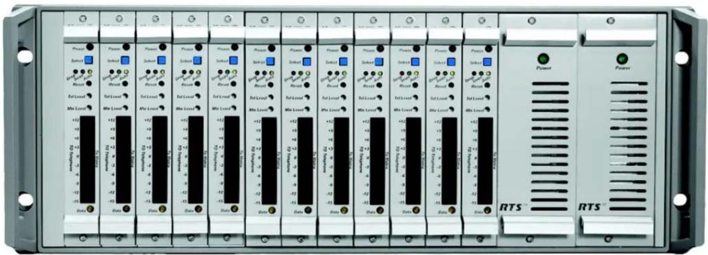
The TIF-4000 is a frame of up to 12 digital telephone interface cards (TIF-4000 front card), with a redundant power supply designed to be compatible with ADAM and Zeus Series Intercoms and Cronus Intercom system. It provides bi-directional communication between the intercom matrix and a standard DTMF capable telephone line. It allows the phone to access all crosspoints of the matrix, as well as dynamic party lines, IFB circuits, and other forms of communications. The 4RU high rack-mountable TIF-4000 provides a transparent link to the telephone system enabling full dial-out capability from any designated keypanel with keypad. The TIF-4000 has full dial-in capability giving the caller a keypanel on the system via commands from the DTMF pad on their telephone. Since the TIF-4000 appears to the matrix as any other keypanel would, the only limitation on the number of units in the system is the same as for other keypanels.

FIGURE 1. TIF-4000 Front and Rear. For a more detailed drawing, see Figure 3.
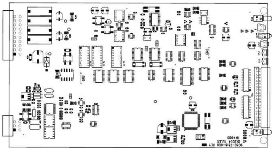
FIGURE 2. TIF-4000 Front Card.
Specifications
Matrix Input/Output 0dBu to +20dBu
Telephone Input/Output ....-30dBu to +6dBu
Noise (200Hz to 3.8kHz)....-40dBu or less
Harmonic Distortion
Intercom Side....-30dBu or less
Telephone Side....-25dBu or less
Frequency Response....300Hz to 3.8kHz +0dB, -6dB
Matrix Connectors
DE-9S Female
RJ12 Female
Telephone Line Connector....RJ11 Female
Telephone Loop-Thru Connector....RJ11 Female
Power Requirements
Universal Power Supply: 100-240 VAC, 50/60Hz
Card:.... Every card uses 1Amp of power
Power Dissipation
TIF-4000 Full Frame (12 TIF Cards)
750mA @ -15V
1A @ +15V
9A @ +5V
TIF-4000 Individual Card
60mA @ -15V
70mA @ +15V
750mA @+5V
Environmental
Operating Temperature: 32°F to 122°F (0°C to 50°C)
Storage Temperature: ...... -22°F to 158°F (-30°C to 70°C)
Dimensions: 19"Wx6.97"Hx12.8"D (25.4mm W x177.038mm H x 325.12mm D)
Weight: 28.45lbs (12.9047kg)
Regulatory Compliance: FCC Part 68, EN 55022/FCC15B
Specifications subject to change without notice.
Reference Views

FIGURE 3. Front of TIF-4000 frame reference view

FIGURE 4. TIF-4000 Reference View - Rear
DIP Switch Settings
DIP Switch (S201) Settings
The TIF-4000 front card DIP switch contains switches to configure the most often changed options. These include: auto-answer on/off, ring signal on/off, password on/off, intercom port address, and full-duplex mode.
Auto-answer (Switch 1)
Turning on the auto-answer option sets the unit to answer the phone automatically when it rings. The number of rings required before it answers is determined by the setting of internal DIP switch (S202). If auto-answer is turned off, the line rings until someone at a keypanel answers the call or until the Select button on the TIF-4000's front card is pressed.
To turn on auto-answer, do the following:
Place switch 1 in the down position.
To turn off auto-answer, do the following:
Place switch 1 in the up position.
Generate Ring Signal (Switch 2)
Turning on the generate ring signal option sets the unit so that when the phone line is ringing, keypanels that are configured to receive ring signals produce an audible ring.
To turn on the ring signal, do the following:
Place switch 2 in the down position.
To turn off the ring signal, do the following:
Place switch 2 in the up position.
Password Required (Switch 3)
Turning on the password required option sets the unit so that when a call is automatically answered, the caller must enter a password via DTMF before the unit allows communications. The password numeric sequence and length are determined by the settings of the internal DIP switch (S203).
To turn on the password required option, do the following:
Place switch 3 (on S201) in the down position.
To turn off the password required option, do the following:
Place switch 3 (on S201) in the up position.
Intercom Port Address (Switches 4-7)
Switches 4 through 7 determine the address of the unit. The port address is expressed in binary with switch 4 being the least significant bit (LSB and switch 7 being the most significant bit (MSB). ADAM and Zeus series systems use a 1-8 address scheme for their ports (e.g. port 1-8 have address 1-8, ports 9-16 have addresses 1-8, etc....).
To turn on (set bit to 1), do the following:
Place the desired switch in the down position.
To turn off (set bit to 0), do the following:
Place the desired switch in the up position.
IMPORTANT: You must set the card address before you put the card into the frame.
TABLE 1. Correspondence between address numbers and intercom port numbers for ADAM, ADAM CS, and Zeus systems
| Address | Card Numbers (bold headings) and Port Numbers | |||||||||||||||||||||||||
| Cards 1 - 25 | ||||||||||||||||||||||||||
| 1 | 2 | 3 | 4 | 5 | 6 | 7 | 8 | 9 | 1 | 0 | 1 | 1 | 1 | 2 | 1 | 3 | 1 | 4 | 1 | 5 | 1 | 6 | 1 | 7 | ||
| 1 1 9 17 25 | 33 | 41 | 49 | 57 6 | 5 73 | 81 89 | 97 1 | 05 1 | 13 12 | 1 129 | 137 | 145 | 153 1 | 61 1 | 69 17 | 7 185 | 193 | |||||||||
| 2 2 10 18 | 26 34 | 42 | 50 | 58 | 66 74 | 82 9 | 0 98 | 106 | 114 1 | 22 130 | 13 | 8 146 | 154 | 162 | 170 1 | 78 186 | 194 | |||||||||
| 3 3 11 19 | 27 35 | 43 | 51 | 59 | 67 75 | 83 9 | 1 99 | 107 | 115 1 | 23 131 | 13 | 9 147 | 155 | 163 | 171 1 | 79 187 | 195 | |||||||||
| 4 4 12 20 | 28 36 | 44 | 52 | 60 | 68 76 | 84 9 | 2 10 | 0 108 | 116 | 124 | 132 1 | 40 148 | 156 | 164 | 172 | 180 | 88 | 196 | ||||||||
| 5 | 5 | 13 | 21 | 29 | 37 | 45 | 53 | 61 | 69 | 77 | 85 | 93 | 101 | 109 | 117 | 125 | 133 | 141 | 149 | 157 | 165 | 173 | 181 | 189 | 197 | |
| 6 | 6 | 14 | 22 | 30 | 38 | 46 | 54 | 62 | 70 | 78 | 86 | 94 | 102 | 110 | 118 | 126 | 134 | 142 | 150 | 158 | 166 | 174 | 182 | 190 | 198 | |
| 7 | 7 | 15 | 23 | 31 | 39 | 47 | 55 | 63 | 71 | 79 | 87 | 95 | 103 | 111 | 119 | 127 | 135 | 143 | 151 | 159 | 167 | 175 | 183 | 191 | 199 | |
| 8 | 8 | 16 | 24 | 32 | 40 | 48 | 56 | 64 | 72 | 80 | 88 | 96 | 104 | 112 | 120 | 128 | 136 | 144 | 152 | 160 | 168 | 176 | 184 | 192 | 200 | |
| Cards 26 - 50 | ||||||||||||||||||||||||||
| 26 27 | 28 | 29 30 | 31 3 | 2 33 | 34 35 | 36 3 | 37 38 | 39 40 | 41 | 42 43 | 44 45 | 46 | 47 48 | 49 50 | ||||||||||||
| 1 | 201 | 209 | 217 | 225 | 233 | 241 | 249 | 257 | 265 | 273 | 281 | 289 | 297 | 305 | 313 | 321 | 329 | 337 | 345 | 353 | 361 | 369 | 377 | 385 | 393 | |
| 2 | 202 | 210 | 218 | 226 | 234 | 242 | 250 | 258 | 266 | 274 | 282 | 290 | 298 | 306 | 314 | 322 | 330 | 338 | 346 | 354 | 362 | 370 | 378 | 386 | 394 | |
| 3 | 203 | 211 | 219 | 227 | 235 | 243 | 251 | 259 | 267 | 275 | 283 | 291 | 299 | 307 | 315 | 323 | 331 | 339 | 347 | 355 | 363 | 371 | 379 | 387 | 395 | |
| 4 | 204 | 212 | 220 | 228 | 236 | 244 | 252 | 260 | 268 | 276 | 284 | 292 | 300 | 308 | 316 | 324 | 332 | 340 | 348 | 356 | 364 | 372 | 380 | 388 | 396 | |
| 5 | 205 | 213 | 221 | 229 | 237 | 245 | 253 | 261 | 269 | 277 | 285 | 293 | 301 | 309 | 317 | 325 | 333 | 341 | 349 | 357 | 365 | 373 | 381 | 389 | 397 | |
| 6 | 206 | 214 | 222 | 230 | 238 | 246 | 254 | 262 | 270 | 278 | 286 | 294 | 302 | 310 | 318 | 326 | 334 | 342 | 350 | 358 | 366 | 374 | 382 | 390 | 398 | |
| 7 | 207 | 215 | 223 | 231 | 239 | 247 | 255 | 263 | 271 | 279 | 287 | 295 | 303 | 311 | 319 | 327 | 335 | 343 | 351 | 359 | 367 | 375 | 383 | 391 | 399 | |
| 8 | 208 | 216 | 224 | 232 | 240 | 248 | 256 | 264 | 272 | 280 | 288 | 296 | 304 | 312 | 320 | 328 | 336 | 344 | 352 | 360 | 368 | 376 | 384 | 392 | 400 | |
| Cards 51 - 75 | ||||||||||||||||||||||||||
| 51 52 | 53 | 54 55 | 56 5 | 57 58 | 59 60 | 61 6 | 62 63 | 64 65 | 66 66 | 67 68 | 69 70 | 71 | 72 73 | 74 75 | ||||||||||||
| 1 | 401 | 409 | 417 | 425 | 433 | 441 | 449 | 457 | 465 | 473 | 481 | 489 | 497 | 505 | 513 | 521 | 529 | 537 | 545 | 553 | 561 | 569 | 577 | 585 | 593 | |
| 2 | 402 | 410 | 418 | 426 | 434 | 442 | 450 | 458 | 466 | 474 | 482 | 490 | 498 | 506 | 514 | 522 | 530 | 538 | 546 | 554 | 562 | 570 | 578 | 586 | 594 | |
| 3 | 403 | 411 | 419 | 427 | 435 | 443 | 451 | 459 | 467 | 475 | 483 | 491 | 499 | 507 | 515 | 523 | 531 | 539 | 547 | 555 | 563 | 571 | 579 | 587 | 595 | |
| 4 | 404 | 412 | 420 | 428 | 436 | 444 | 452 | 460 | 468 | 476 | 484 | 492 | 500 | 508 | 516 | 524 | 532 | 540 | 548 | 556 | 564 | 572 | 580 | 588 | 596 | |
| 5 | 405 | 413 | 421 | 429 | 437 | 445 | 453 | 461 | 469 | 477 | 485 | 493 | 501 | 509 | 517 | 525 | 533 | 541 | 549 | 557 | 565 | 573 | 581 | 589 | 597 | |
| 6 | 406 | 414 | 422 | 430 | 438 | 446 | 454 | 462 | 470 | 478 | 486 | 494 | 502 | 510 | 518 | 526 | 534 | 542 | 550 | 558 | 566 | 574 | 582 | 590 | 598 | |
| 7 | 407 | 415 | 423 | 431 | 439 | 447 | 455 | 463 | 471 | 479 | 487 | 495 | 503 | 511 | 519 | 527 | 535 | 543 | 551 | 559 | 567 | 575 | 583 | 591 | 599 | |
| 8 | 408 | 416 | 424 | 432 | 440 | 448 | 456 | 464 | 472 | 480 | 488 | 496 | 504 | 512 | 520 | 528 | 536 | 544 | 552 | 560 | 568 | 576 | 584 | 592 | 600 | |
| Cards 76 - 100 | ||||||||||||||||||||||||||
| 76 77 78 | 79 80 | 81 82 83 | 84 85 86 87 88 | |||||||||||||||||||||||
| 1 | 601 | 609 | 617 | 625 | 633 | 641 | 649 | 657 | 665 | 673 | 681 | 689 | 697 | |||||||||||||
| 2 | 602 | 610 | 618 | 626 | 634 | 642 | 650 | 658 | 666 | 674 | 682 | 690 | 698 | |||||||||||||
| 3 | 603 | 611 | 619 | 627 | 635 | 643 | 651 | 659 | 667 | 675 | 683 | 691 | 699 | |||||||||||||
| 4 | 604 | 612 | 620 | 628 | 636 | 644 | 652 | 660 | 668 | 676 | 684 | 692 | 700 | |||||||||||||
| 5 | 605 | 613 | 621 | 629 | 637 | 645 | 653 | 661 | 669 | 677 | 685 | 693 | 701 | |||||||||||||
| 6 | 606 | 614 | 622 | 630 | 638 | 646 | 654 | 662 | 670 | 678 | 686 | 694 | 702 | |||||||||||||
| 7 | 607 | 615 | 623 | 631 | 639 | 647 | 655 | 663 | 671 | 679 | 687 | 695 | 703 | |||||||||||||
| 8 | 608 | 616 | 624 | 632 | 640 | 648 | 656 | 664 | 672 | 680 | 688 | 696 | 704 | |||||||||||||
TABLE 2. Address DIP Switch Settings
| Logical Keypanel Number | DIP Switch Settings | |||
| SW4 SW | 5 SW6 SW7 | |||
| 1 Closed | Open Open | Open | ||
| 2 Open | Closed Open | Open | ||
| 3 Closed | Closed Open | Open | ||
| 4 Open | Open Closed | Open | ||
| 5 Closed | Open Closed | Open | ||
| 6 Open | Closed Closed | Open | ||
| 7 Closed | Closed Closed | Open | ||
| 8 Open | Open Open | Closed | ||
| 9 Closed | Open Open | Closed | ||
| 10 Open | Closed Open | Closed | ||
| NOTE: Shaded areas is for CS9xxx system addresses only. | ||||
To set the address for ADAM or Zeus systems, do the following:
- Determine the port number used for the TIF-4000.
- Locate the port number and its corresponding address in Table 1 on page 11.
- Determine the DIP switch settings by looking up the address determined in the previous step in Table 2 on page 12.
- Set the DIP switches on the back of the unit.
Full Duplex Method Switch 8 (S201)
Switch 8 (S201) controls the method by which full-duplex operation is implemented in the unit. This switch only works if full-duplex mode is set via internal DIP switch (S202), switch 7 (factory default setting for Switch 7 is off, full-duplex mode). If switch 8 is in the OPEN position, then the unit is forced into full-duplex mode all the time. If switch 8 (S201) is in the closed position, then the unit is forced into full-duplex mode only when audio is present.
When using full-duplex mode, users may hear an increased amount of echo on the line. This may be more pronounced when the TIF-4000 is forced into full-duplex mode all of the time (switch 8 is open) rather only when audio is present (switch 8 closed).
Internal DIP Switch (S202)
Internal DIP switch, see Figure 5, is accessed by removing the card from the frame.
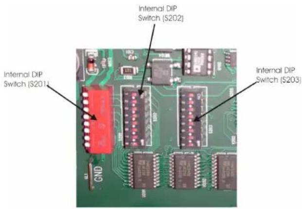
FIGURE 5. TIF-4000 Internal DIP Switch Locations
TABLE 3. Ring Count Settings
| # of Rings SW1 SW2 | ||
| 1 | o | f f o f |
| 2 | o | n o f |
| 4 | o | f o n |
| 8 | o | n o n |
Ring Count
Switches 1 and 2 determine the number of rings before the unit auto-answers. The ring count is approximate. The switches have no effect unless switch 1 on the rear panel DIP switch bank is in the down position. To set the ring count, see Table 3.
DTMF Or Pulse Dial Selection
Switch 3 sets the dialing mode to either DTMF (Dual Tone Multi-Frequency, also known as touch tone) or Pulse. When the switch is in the off position, the DTMF dialing is selected. When the switch is in the on position, pulse dialing is selected.
Point-to-point Seize
Switch 4 turns on and off the point-to-point seize feature. When the switch is in the off position, the normal line seize operation (via the keypanel) is selected. When the switch is in the on position a line is seized immediately upon the designated TIF-4000's talk key being pressed via the keypanel.
One Touch Dial
Switch 5 enables/disables the one touch dialing feature. When the switch is in the off position, one touch dialing is disabled. When the switch is in the on position, one-touch dial is enabled.
One touch dialing works as follows:
If a number is stored in Auto-Dial memory 1 on the TIF-4000, and the line is on-hook, then the TIF-4000 autodials the number stored in Autodial memory 1 whenever any keypanel closes a point-to-point talk key to the TIF-4000.
Fast Seize
Switch 6 enables/disables the fast seize feature. If the switch is in the off position, fast seize is disabled. If the switch is in the on position, fast seize is enabled. If fast seize is enabled and the unit is set to auto-answer, then the TIF-4000 answers or seize the line at the start of the first ring.
NOTE: A ring is not heard on any of the keypanels when fast seize is enabled.
DSP Full Or Half-Duplex Selection
Switch 7 determines either full-duplex or half-duplex operation. If the switch is set to the off position, the DSP is forced into full-duplex mode as determined by the setting of switch 8 on the DIP switch bank located on the rear panel of the TIF-4000. For more information, see “Full Duplex Method Switch 8 (S201)” on page 12. If the switch is set to the on position, the DSP is never forced into full duplex.
Audio Ducking
Switch 8 enables/disables the audio ducking feature. If the switch is set to the off position, audio ducking is disabled. If the switch is set to the on position, audio ducking is enabled. The audio ducking feature helps eliminate feedback between the intercom system and the telephone line.
Internal DIP Switch (S203)
Internal DIP switch (S203) selects the password and call progress IC type. Switch 6 must be set to match the type of call progress IC is installed in the unit at location U204. The switch is preset at the factory in the Open position if the IC installed at location U204 is a M-985-0 or in the closed position, if an M-982-02 is installed at location U204. Switch 6 is also part of the password if a password is required. When password required is enabled, the password must be entered via DTMF by the caller before they may communicate. This is to prevent unauthorized use of the intercom by callers.
Switches 7 and 8 select the length of the password, from 1 digit to 4 digits. If set for 1 digit only, the first digit of the password is used., if set for 2 digits, then the first digits are used, etc. See Table 4.
TABLE 4. Password Lengths Configuration
| PW Length SW7 SW8 | ||
| 4 | o | f |
| 3 | o | n |
| 2 | o | f |
| 1 | o | n |
| f | o | f | f |
| o | f | f | |
| f | o | n | |
| o | n |
Connections
Intercom
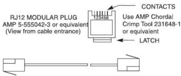
Use either of the To Matrix connectors (but not both) to connect to an intercom port. The intercom port that you connect to will determine the address of the unit (see Setting Address). Cable wiring diagrams are shown in Figure 6 and Figure 7. An LED labeled DATA is located on the front card and serves as a basic indicator of data being present.
Telephone and Telephone Line
There are two (2) telephone connections provided on each card in the TIF-4000. Plug the telephone line into the jack labeled Phone Line. You may also plug a standard telephone into the jack labeled Loop Thru.
CAUTION: To reduce the risk of fire, use only No. 26 AWG or larger (e.g., 24 AWG) UL Listed or CSA Certified Telecommunication Line Cord.
NOTE: The standard telephone plugged into the Loop Thru jack is disconnect when the TIF-4000 seizes the telephone line. For cabling information, see “TIF to Phone Cables” on page 16.
Relay
A relay is a switch that is open or closed. In the case of the TIF-4000, when it is off-hook (a call is active), the switch is closed and an indicator, such as an external lamp, can be activated.
Setting Audio Levels
Audio levels to the intercom matrix and to the telephone line can be adjusted via the trim pots located on the front card.
Setting Audio Levels to Intercom Matrix
Adjustments may be made via the front card pots (see Figure 1).
To adjust the pot, do the following:
- Using a small flat blade screwdriver, set the front card level control for mid-range.
- Have the caller talk at their normal level.
- Adjust the control for the best audio quality while avoiding going into the red section of the audio meter (to Matrix) located on the front panel.
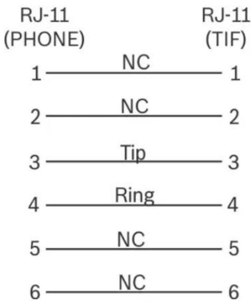
Cable Drawings TIF to Phone Cables
3 TWISTED PAIR TELEPHONE CABLE
PAIR 1: AUDIO TO MATRIX
PAIR 2: AUDIO FROM MATRIX
PAIR 3: DATA

flowchart
graph LR
    A["1"] --> B["DATA -"]
    C["2"] --> D["AUDIO FROM MATRIX +"]
    E["3"] --> F["AUDIO TO MATRIX +"]
    G["4"] --> H["AUDIO TO MATRIX -"]
    I["5"] --> J["AUDIO FROM MATRIX -"]
    K["6"] --> L["DATA +"]
    B --> M["1"]
    D --> N["2"]
    F --> O["3"]
    H --> P["4"]
    J --> Q["5"]
    L --> R["6"]
FIGURE 6. RJ12 Intercom Cable
flowchart
graph TD
    A["RJ-11 (PHONE)"] -->|NC| B["RJ-11 (TIF)"]
    C["1"] -->|NC| D["1"]
    E["2"] -->|NC| F["2"]
    G["3"] -->|Tip| H["3"]
    I["4"] -->|Ring| J["4"]
    K["5"] -->|NC| L["5"]
    M["6"] -->|NC| N["6"]
FIGURE 8. Phone to TIF (US)

* When connecting to an ADAM CS back panel, use only low-profile cable connectors such as AMP Part No. 747516-3

flowchart
graph TD
    A["RJ-11 (PHONE)"] -->|1 NC| B["2"]
    A -->|3 NC| C["4 NC"]
    A -->|5| D["6 NC"]
    E["RJ-11 (TIF)"] -->|NC 1| F["3"]
    E -->|NC 2| G["4"]
    E -->|NC 5| H["NC 6"]
FIGURE 9. Phone to TIF (UK)
FIGURE 7. DE9 Intercom Cable
TABLE 5. Password length DIP switch settings
| Password | SW1 | SW2 | SW3 | SW4 | SW5 | SW6 | ||
| 4,7,8,8 | off | off | off | off | off | |||
| 7,7,7,7 | on | off | off | off | off | |||
| 4,6,8,7 | off | on | off | off | off | |||
| 1,0,5,8 | on | on | off | off | off | |||
| 1,4,8,4 | off | off | on | off | off | |||
| 7,0,3,3 | on | off | on | off | off | |||
| 5,9,0,7 | off | on | on | off | off | |||
| 0,9,3,5 | on | on | on | off | off | |||
| 3,7,8,0 | off | off | off | on | off | |||
| 1,4,5,0 | on | off | off | on | off | |||
| 6,9,2,7 | off | on | off | on | off | |||
| 8,3,0,3 | on | on | off | on | off | |||
| 8,3,3,6 | off | off | on | on | off | |||
| 6,0,8,0 | on | off | on | on | off | |||
| 2,9,5,7 | off | on | on | on | off | |||
| 5,8,5,1 | on | on | on | on | off | |||
| 9,5,9,9 | off | off | off | off | off | |||
| 8,2,0,6 | on | off | off | off | off | |||
| 4,7,4,0 | off | on | off | off | on | off | ||
| 4,5,7,3 | on | on | off | off | on | off | ||
| 8,8,3,0 | off | off | on | off | on | off | ||
| 0,6,2,0 | on | off | on | off | on | off | ||
| 3,3,3,9 | off | on | on | off | on | off | ||
| 9,8,5,0 | on | on | on | off | on | off | ||
| 7,3,5,6 | off | off | off | on | on | off | ||
| 9,1,4,6 | on | off | off | on | on | off | ||
| 9,9,9,1 | off | on | off | on | on | off | ||
| 3,8,8,1 | on | on | off | on | on | off | ||
| 4,2,4,0 | off | off | on | on | on | off | ||
| 1,0,6,3 | on | off | on | on | on | off | ||
| 8,6,3,2 | o | f | f | o | n | o | n | o |
| 4,2,3,4 | on | on | on | on | on | off | ||
| 0,8,5,1 | off | off | off | off | off | |||
| 0,6,7,4 | on | off | off | off | off | |||
| 0,0,1,5 | off | on | off | off | off | |||
| 6,2,9,4 | on | on | off | off | off | |||
| 9,9,5,4 | off | off | on | off | off | |||
| 1,0,7,9 | on | off | on | off | off | |||
| 9,0,3,0 | off | on | on | off | off | |||
| 0,1,6,6 | on | on | on | off | off | |||
| 9,5,5,6 | off | off | off | on | off | |||
| 8,0,5,4 | on | off | off | on | off | |||
| 6,2,9,3 | off | on | off | on | off | |||
| 6,6,1,1 | on | on | off | on | off | |||
| 6,3,6,7 | off | off | on | on | off | |||
| 1,5,2,9 | on | off | on | on | off | |||
| 2,7,5,6 | off | on | on | on | off | |||
| 8,3,1,3 | on | on | on | on | off |
TABLE 5. Password length DIP switch settings
| Password | SW1 | SW2 | SW3 | SW4 | SW5 | SW6 | ||
| 1,6,5,6 | off | off | off | on | on | |||
| 7,6,4,2 | on | off | off | on | on | |||
| 1,6,5,3 | off | on | off | off | on | on | ||
| 1,6,0,3 | on | on | off | off | on | on | ||
| 4,3,7,3 | off | off | on | off | on | on | ||
| 3,5,7,4 | on | off | on | off | on | on | ||
| 4,7,6,4 | off | on | on | off | on | on | ||
| 3,8,6,8 | on | on | on | off | on | on | ||
| 5,7,1,9 | off | off | off | on | on | on | ||
| 3,9,2,7 | on | off | off | on | on | on | ||
| 6,8,5,7 | off | on | off | on | on | on | ||
| 5,4,8,7 | on | on | off | on | on | on | ||
| 3,2,5,2 | off | off | on | on | on | on | ||
| 0,4,0,1 | o | n | o | f | f | o | n | o |
| 6,4,0,9 | o | f | f | o | n | o | n | o |
| 4,3,4,3 | on | on | on | on | on |
Setting Audio Level to Telephone Line
Adjustment may be made via the front card control (see Figure 1). To adjust the control use a small flat blade screwdriver or trim pot adjust tool. Initially, set the front card level control for mid-range. Have the caller talk at their normal level and adjust the control for the best audio quality, while avoiding going into the red section of the audio meter (to Telephone) located on the front card.
n o n o f f
Configuring for Country's Telephone System
The TIF-4000 should be configured to work with the telephone system to which it is connected. Each country or area of the world has unique signalling differences that could cause erratic operation of the TIF-4000 if it is not properly configured. If the system you intend to connect to is not currently supported, you may request a configuration, using the form located in the back of this manual.
To configure the unit for use with a specific country's telephone system, do the following:
NOTE: AZedit must be configured to allow firmware downloads.
- Connect the TIF-4000 to the intercom system.
- Run AZedit and go to the Keypanel Software Versions window (Status|Software Versions|Keypanels).
- Click the entry for the TIF-4000 you wish to configure.
NOTE: Configurations are in a self-extracting archive on the included on the AZedit cd.
-
Extract and copy these files to a known location on the computer connected to the intercom matrix.
-
Press Ctrl+Shift+D to start the software download process. A download screen appears.
-
Select the location you copied the files to in step 4 and select the file corresponding to the country needed.
-
Click OK.
Once the software versions window appears, the process is complete.
The status reported for the TIF-4000 contains a number corresponding to the country configuration. This is reported as LOCALE=XX, where XX is a specific number for each country. The possible configurations are:
TABLE 6. Country Codes
| LOCALE # Country or | Countries | |||
| 0 North America, Korea, | Taiwan | |||
| 1 | B | c | l | g |
| 2 France | ||||
| 3 | G | c | r | m |
| 4 United Kingdom (UK) | ||||
| 5 | I | t | a | l |
| 6 | J | a | p | a |
| 7 Netherlands | ||||
| 8 Norway | ||||
| 9 | N | o | t | U |
| 10 Singapore | ||||
| 11 Brazil, Sweden | ||||
| 12 Ireland | ||||
| CUST Custom Configuration | ||||
Operation From a Keypanel
The TIF-4000 is operated from the intercom keypanels, and from the dial pad on the telephone at the remote end of the line. Any keypanel with a keypad may use a TIF-4000. All that is necessary is to program a key to talk to the TIF-4000, as if it were a keypanel. The alpha numeric display or tally LED for that key then provides information about the phone line. A solid display or non-illuminated LED indicates a line which is not in use. A slow flash indicates a line which is in use (off-hook). A rapidly flashing display or LED indicates a line which is ringing. In addition, the alpha numeric display shows digits as they are dialed, and the LED flashes for each digit.
NOTE: Displayed tallies are different if the Don't Generate Tallies for TIF or Trunk Use option has been selected in Options|Intercom Configurations|Options.
Programming a Key to Use the TIF-4000
To use the TIF-4000, either to answer a call, or to call out, you first need to program a key to talk to the TIF-4000. This is accomplished in the same manner as programming a key to talk to a keypanel. To program a key by port number, enter NUM-nnn_PGM-t, where NUM is the number 1 key, nnn is the port number of the TIF-4000 you want to use, and t is any talk key. You also need to use the listen key, so it should be assigned as either AF (auto-follow) or AL (auto-listen).
NOTE: The TIF-4000 only responds to commands which are sent via a point-to-point key assignment. If you wish to use the TIF-4000 primarily on a PL, you must add a point-to-point assignment as the L2 talk assignment on the talk key for any panels which are going to either answer the line, or dial out on the line.
Dialing a Call
To dial a call on the TIF-4000 using a or KP-32, do the following:
- Turn on the listen key for the line you wish to dial on. This allows you to hear dial tone, and your DTMF dialing tones.
-
Enter dial mode by entering PHONE-PGM-T. PHONE is the 4 button on the keypad. PGM is on the keypad, and T is the talk key which is programmed to talk to the TIF-4000 you are dialing on. Leave the talk key in the latched position as you dial the number.
-
Dial the number. As you enter each digit, it appears in the alpha display above the key you are dialing on. If the listen key is latched, you hear each DTMF tone as it is generated.
-
When you have completed dialing, momentarily turn off the talk key to exit dial mode. The alpha numeric display reverts to normal, and you may use the key and keypad in the normal manner.
NOTE: Digits 0-9 generate the DTMF digits 0-9. PGM generates the #, and CLR generate * (# and * are displayed for these keys).
It is necessary to press CLR twice if you wish to generate an *, as a single CLR is used to trigger the speed dial and redial features.
To dial a call on the TIF-4000 using a KP-12 or KP-32, do the following:
- Tap the phone key to begin your call. This places the keypanel in dial mode: the CALL indicator turns on, and the MAN DIAL (manual dial) displays in the call waiting window. You should also hear the dial tone.
NOTE: You can hang up the phone line at this time by simply tapping the phone key again.
-
Tap SEL (select) to select MAN DIAL. The twelve intercom keys can now be used to dial a telephone number. Each key corresponds to the number printed next to it on the front of the panel. If the keypanel has alphanumeric displays, the key numbers are displayed above each key.
-
Begin dialing the number by tapping the appropriate keys. After you dial the first digit, END DIAL appears in the call waiting window.
-
When you have completed the dialing, tap SEL to select END DIAL. This returns the keypanel to normal operating mode. If the called party answers, proceed with your conversation.
Hanging Up
The TIF-4000 detects the call at the far end has hung up under most circumstances. It detects the hang up by either loop interrupt, battery reversal, or the presence of a dial tone or busy signal. Some telephone systems do not provide any of the above, so it is necessary to force a hang up. In addition, if the call was placed to an auto-answer device, it is necessary to force a hang up when the call is complete.
Enter PHONE-CLR-t, where PHONE is the 4 on the keypad, CLR is the CLR button, and t is the talk key which is programmed to talk to the TIF-4000which you want to hang up. This disconnects the line for which you struck the talk key.
NOTE: If talk is in the on position, you must turn off the key, then momentarily turn it on again to indicate which line you wish to disconnect. If the line is in dialing mode, then you must first exit dialing mode by turning off the key, then use PHONE-CLR-t to hang up.
Re-dialing the Last Number
The TIF-4000 remembers the last number which it has dialed.
To redial the last number, do the following:
- Enter dialing mode by following instructions for dialing a call.
-
Enter CLR-0-0.
The TIF-4000 automatically redials the last number it dialed. -
Momentarily release the talk key to exit dialing mode.
EXAMPLE: If you have a call to 818.556.6700 and you are disconnected, issuing the redial command reestablishes the call. The redial command may be issued from any keypanel in the intercom, not just the keypanel that originally dialed the call.
Dialing a Speed Dial Number
The TIF-4000 has 24 internal memories for storing frequently used phone numbers.
To dial one of these numbers, do the following:
- Enter Dial mode.
- Enter CLR-nn, where CLR is the clear button on the keypad, and nn is two digits, which are the speed dial code.
- Momentarily release the talk key to exit the dialing mode.
Storing a Speed Dial Number
- After making a call manually, but before exiting dial mode, enter the CLR-PGM-nn before you release the talk key to exit dialing mode.
- Momentarily release the talk key to exit dialing mode.
NOTE: To generate a pause during auto dial, enter *99. This is used, for example, if you need to enter a digit to get an outside line, and you r phone system requires a pause before continuing to dial.
Each number may contain up to 25 digits.
A TIF-4000 can have different numbers stored in it. The TIF-4000 stores the numbers in non-volatile memory and therefore does not require a UPS to maintain stored speed dial numbers.
Answering a Call
When a line is ringing, the alpha-numeric display or LED above the talk key which is programmed for that line flashes rapidly.
To answer a call, do the following:
- Turn the listen key on.
- Press the talk key and speak into the microphone or headset.
NOTE: If the keypanel is programmed as a default station, you panel rings whenever one of the lines rings. If you do not have a key already programmed, the ringing line appears in the CWW window. To answer, press the incoming call key and answer. You should copy the key to a main key position, either just before or just after you answer, so you can turn on the listen key to hear the caller audio.
TIF-4000 System Setup To Receive Calls
To the intercom system, the TIF-4000 is similar to a keypanel. If the phone lines are to be used for outgoing calls only, then no programming in AZedit is necessary. If users are going to phone into the intercom system from the outside, then the TIF4000 needs to be configured to allow them to use the phone line in mush the same way a local user uses the keypanel.
Programming the information for the phone line is entered into AZedit just as if the TIF-4000 where an ordinary keypanel, by selecting Keys from the main menu, then selecting TIF-4000 from the drop down menu of keypanels. The TIF-4000 operates much the same way as a keypanel, except the keys are really the DTMF buttons on the user's telephone.
Auto-Answer Mode
To use the TIF-4000 in auto-answer mode, you must first enable auto-answer mode on the front card DIP switch bank, switch 1. You may also wish to enable Password Required, switch 3. In addition, you may select the number of rings before the unit answers (internal DIP switch bank #2), and the actual password (internal DIP switch bank #3).
When the caller dials into the TIF-4000, they hear the line ring, then the unit answers and beep to request the password (if password required is enabled). The user must enter the password. The unit beeps once to confirm a proper password. If the password is not correct, the unit beeps twice to allow another try. The user is allowed three (3) attempts to enter the correct password, after which the TIF-4000 disconnects.
Once the password has been entered, the TIF-4000 establishes communications on key #1 automatically. From AZedit, this is talk and listen key #1. If, for example, the user is a camera operator, it may be desirable to program the camera PL as talk and listen on talk and listen keys #1. If the caller were a reporter, you might want to program an IFB on listen key #1 but no talk key #1.
Keys 2 and 7 may also be programmed. To use the other keys from the phone, just press the DTMF button for the key you wish to use. For example, if key #1 was the camera PL, and you have finished with the shot, you may press #1, which toggles off key 1. If master control were programmed on key #2, you may then press 2 and call master control. Likewise, you might have an IFB programmed on listen 3, with no talk. If you press 3, you hear the IFB. #4 could have an IFB talk on it, to allow a caller to speak on an IFB circuit.
Each DTMF button acts as if it were on a push on/push off switch. When programming in AZedit, program the same key number as the number the user is going to press on the telephone to speak.
Talk keys 8 to 15 have a special purpose. If you are not using auto-answer mode, but have setup the TIF-4000 to be manually answered, talk keys 8 to 15 are programmed for the keypanels which are to receive the ring signal. They may also be toggled on and off from the phone by DTMF 8, so they may be used in auto-answer mode as well. You may program only key 8, in which case it behaves the same as keys 1-7. You may also program additional keypanels, PLs, IFBs, etc. on keys 9-15, and they are activated simultaneously by the 8 button on the phone.
Manual Answer Mode
In manual answer mode, the line rings until it is answered from a keypanel. In general, you must designate panels which are to receive the ring, so they can answer the line. When a line is manually answered, the caller does not have to enter a password, even if the password required switch is turned on. You may mix modes by enabling auto-answer, but setting the ring count for 8 rings. If no user has answered the call by 8 rings, the TIF-4000 automatically answers the call, and if the password required is enabled, the call is screened by requiring a password.
To use manual answer mode, you may choose to program keys 1 to 7 as above, if you want. When the phone is manually answered, key 1 is not automatically activated, but the caller may activate any of the keys if he wishes.
You must also designate the panels which are going to ring when the line rings. Program these panels on keys 8 to 15, using both L1 and L2 if you have more than 8. It is generally not necessary to program the listen keys on these positions. When the line rings, the TIF-4000 calls these panels when the line is ringing. The TIF-4000 generates a ringing noise which is then transmitted to these panels. The panels display the TIF-4000's alphanumeric in the incoming call window (CWW), and if a talk key has already been programmed on the panel, its alphanumeric flashes rapidly.
Using the TIF-4000 From the Telephone
The TIF-4000 behaves differently depending on how it is programmed. It is up to the operator who programs the TIF-4000 to convey to the user what to expect. If the user is not familiar with the operation of the TIF-4000, it is best to keep the operation as simple as possible. For this reason, it is suggested that you not use password required unless you have had problems with nu8isance calls in the past. If the TIF-4000 field user only requires one service, it is best to program that service on key 1, enable auto-answer, and disable password required. The telephone user only has to dial the proper phone number to use the interface. As they become more familiar with its operation, you can then being to offer more options to the users, or begin to require a password.
When calling in, if the unit is in auto-answer mode, it answers the call after the number of rings which have been selected. If password required is not enabled, the unit indicates it is ready with a single beep. If password required is enable, the TIF-4000 prompts for a password with 2 beeps. The user enters the password, and the unit either beeps once if the password is correct, or twice if it is wrong. The user is allowed three (3) attempts to enter the password, after which the TIF-4000 disconnects. In the event a user calls the TIF-4000 when the intercom system is either turned off or absent, the TIF-4000 answers and prompt with three (3) beeps.
Once the password is entered, the TIF-4000 enable talk and listen on key 1. This should be programmed ahead of time to whatever communications the caller generally needs first. If it is not desirable for the caller to be able to talk at this point, then only the listen key for key 1 should be programmed.
The caller may then either continue to use key 1 or select other keys with their DTMF pad. They may turn off key 1 by pressing DTMF 1, or may continue to add other keys. At any time, the caller may turn off all keys without hanging up by press 0. When the call is complete, the caller should enter *#, which causes the TIF-4000 to disconnect. This is more reliable than waiting for the phone system to pass the disconnect information to the TIF-4000.
DTMF Codes
Once programmed, the TIF-4000 may be operated via the DTMF keypad on the telephone. The DTMF keys have the following functions:
Normal Mode
1 thru 7 Toggle on and off talk and listen #1 to #7.
NOTE: Initially #1 is enabled if the unit auto-answered the line.
Toggle on and off talk and listen to the panels which ring when the line is ringing. This allows the caller to recall the panels
8 without having to hang up and redial. Toggling this on allows the callers voice to be hear from all the panels which normally ring.
9 Enters programming mode, to reassign keys.
Turn off all talk and listen keys. Since 1-8 are toggles, it is possible to forget which
0 keys are on and which are off. In this case, just press 0 to turn them all off and start over.
Toggle on and off listen 1-7. By pressing * before the key, you only effect the listen.
This allows you to listen to a circuit without talking to it, or to talk to a circuit
*1 thru *7 without listening to it.
NOTE: You automatically listen and talk to #1 if the TIF-4000 auto-answered the line.
*8 Toggle on and off listen for 8-15.
Disconnect. This causes the TIF-4000 to hang up. It is a good idea to do this before
*# you hang up, as many phone systems take a long time to signal that the far end has hung up.
Programming Mode
You may reprogram the talk and listen assignments on 1-7, just as you can on a keypanel (if they are not restricted via AZedit). Note, the sequences are the same as the sequence you would use from a keypanel, except that you must first enter programming mode by pressing 9.
NOTE: The use of programming mode is discouraged due to a lack of feedback to the user to verify a programming sequence.
I nn # K Program a talk key to a point-to-point.
2 nn # K Program a talk key to a PL.
01 nn #K Program a talk key to a special list.
02 nn #K Program a talk key to an IFB
03 nn # K Program a talk ISO.
04 nn # K Program a talk key relay.
3 5 # K Program a talk key to all call (turn on the lower numbered talk keys.
I nnn # *K Program a listen key to point-to-point key.
2 nn # *K Program a listen key to a PL.
3 2 # *K Program a listen key to auto follow.
3 3 # *K Program a listen key to auto mute.
01 nn # *K Program a listen key to a special list.
02 nn # *K Program a listen key to an IFB.
03 nn # *K Program a listen ISO.
04 nn # *K Program a listen key to a relay.
*9 Exit programming mode.
*0 Exit programming mode and turn off all talk and listen keys.
*# Disconnect
NOTE:
- 0-9 are the number keys, * and # are the star and pound keys.
- nnn is the three digit panel number.
- nn is the two digit number for IFB, PL Relay, Special List, or ISO.
- K is a key which you are programming, just press the digit (1-7). This is used to represent the listen key.
Telephone Interface Requirements Form
The RTS TIF-4000 Digital Hybrid Telephone Line Interface has been designed to respond to ringing for auto-answer and to respond to a number of conditions to detect hang-up. These conditions are (in the standard product) based upon the telephone systems of the US and other select countries. PBX (Private Branch Exchange) systems in the US and other countries may have ringing and hang-up characteristics which differ from the design parameters used in the TIF-4000. Public telephone systems in countries other than those currently supported by Bosch Security Systems, Inc may have ringing and hang up characteristics which differ from the design parameters used in the TIF-4000. Additionally, some countries require governmental approval for connection of the TIF-4000 to the public telephone system. Bosch Security Systems, Inc handles these requirement on a case by case basis and may require a onetime engineering fee to adapt the TIF-4000 for a specific telephone system or to obtain governmental approval. Additionally, Bosch Security Systems, Inc may require the customer to initiate the government approval process of the TIF-4000 for their particular telephone system.
Here is a form which can be used to obtain the required specific technical information.
Termination impedance matching (off-hook): ____
Termination impedance matching (on-hook): ____
Protection devices required:
Return loss: ____ dBm
Maximum allowable transmit level: ____ dBm
Hi-pot Tests:
Tip to ring:
Tip to ground:
Ring to ground:
Ring Signal:
Frequency____ HzCadence:____ sec.onsec. off____
Disconnect Signal:
Loop Drop:Y____ N____
Loop Reversal: Y ____ N ____
Audio Signal: Y ____ N ____
If Y, frequency of tone (s): ____
Cadence: ____ sec.on sec. off ____
DTMF dialing: frequencies
duration: ____ msec.interdigit pause: ____ msec.
Pulse Dialing: pulse rate: ____ Hz break-to-make ratio: ____ : ____
Hook Flash Break Duration: ____ msec. min. ____ msec. max
- Digital Hybrid Telephone Line
- PROPRIETARY NOTICE
- COPYRIGHT NOTICE
- WARRANTY AND SERVICE INFORMATION
- CUSTOMER SUPPORT
- TECHNICAL QUESTIONS EMEA
- DISCLAIMER
- Important Safety Instructions
- Table
- of
- Contents
- INTRODUCTION 3
- INSTALLATION 9
- OPERATION 19
- Introduction
- IMPORTANT:
- Description
- Specifications
- DIP Switch Settings
- DIP Switch (S201) Settings
- Auto-answer (Switch 1)
- Generate Ring Signal (Switch 2)
- Password Required (Switch 3)
- Intercom Port Address (Switches 4-7)
- Full Duplex Method Switch 8 (S201)
- Internal DIP Switch (S202)
- Ring Count
- DTMF Or Pulse Dial Selection
- Point-to-point Seize
- One Touch Dial
- Fast Seize
- DSP Full Or Half-Duplex Selection
- Audio Ducking
- Internal DIP Switch (S203)
- Connections
- Intercom
- Telephone and Telephone Line
- Relay
- Setting Audio Levels
- Setting Audio Levels to Intercom Matrix
- Setting Audio Level to Telephone Line
- Configuring for Country's Telephone System
- Operation From a Keypanel
- Programming a Key to Use the TIF-4000
- Dialing a Call
- Hanging Up
- Re-dialing the Last Number
- Dialing a Speed Dial Number
- Storing a Speed Dial Number
- Answering a Call
- TIF-4000 System Setup To Receive Calls
- Auto-Answer Mode
- Manual Answer Mode
- Using the TIF-4000 From the Telephone
- DTMF Codes
- Normal Mode
- Programming Mode
- NOTE:
- Telephone Interface Requirements Form
Brand : RTS
Model : TIF-4000
Category : Telecommunication Equipment