Control 384 - Uncategorized Audibax - Free user manual and instructions
Find the device manual for free Control 384 Audibax in PDF.


| Product Type | DMX-512 Lighting Controller |
| Brand | Audibax |
| Model | Control 384 |
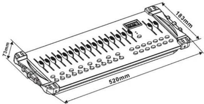
| Dimensions | 520 x 183 x 73 mm |
| Weight | 3.0 kg |
| Power Supply | DC 9V-12V, 500mA minimum; includes AC adapter (90V~240V) |
| Number of Channels | 384 total (24 fixtures x 16 channels) |
| Fixture Control | Up to 24 intelligent lights |
| Banks | 30 banks, each with 8 scenes |
| Scenes | 240 programmable scenes total |
| Chases | 6 chases, each with up to 240 steps |
| Control Sliders | 16 universal channel sliders |
| MIDI Control | Yes – over banks, chases, and blackout |
| Built-in Microphone | Yes – for sound-active mode |
| DMX Connectors | 3-pin XLR male (input) and female (output) |
| Display | LED status window |
| Gooseneck Lamp | LED gooseneck lamp included |
| Housing Material | Plastic end housing |
| Protocol | DMX-512 USITT |
| Maximum Ambient Temperature | 45°C (113°F) |
| Included Accessories | Controller, power adapter, manual, LED gooseneck lamp |
| Safety Instructions | Indoor use only; disconnect power before servicing; do not repair yourself |
Frequently Asked Questions - Control 384 Audibax
User questions about Control 384 Audibax
0 question about this device. Answer the ones you know or ask your own.
Ask a new question about this device
Download the instructions for your Uncategorized in PDF format for free! Find your manual Control 384 - Audibax and take your electronic device back in hand. On this page are published all the documents necessary for the use of your device. Control 384 by Audibax.
USER MANUAL Control 384 Audibax
4.4 Technical Specifications
Dimensions: 520x183x73mm
Weight: 3.0Kg
Operation Range: DC 9V-12V 500Ma MIN
Maximum ambient temperatura: 45°C
Data Input: locking 3-pin XLR male socket
Data output: locking 3-pin XLR female socket
Data pin configuration: pin 1 shield, pin 2(-), pin 3 (+)
Protocols: DMX-512 USITT
AUDIBAX
Control 384
Please read the manual before using the product

Control 384
USER'S
MANUAL
Contents
1. Before you begin
1.1 What are included....2
1.2 Using instruction....2
1.2 Unpacking Instructions....2
1.3 Safety instructions....2
2. Installation
2.1 Features....2
2.2 General overview....3
2.3 Product overview (front)....2
2.4 Product overview (rear panel) 4
2.5 Common terms....4
3. Operating instructions
3.1 SETUP
3.1.1 Setting up the System....5
3.1.2 Fixture Addressing....5
3.1.3 Box and tilt channels....5
3.1.4 Resetting the system
3.1.5 Copy Scanner....6
3.1.6 Fade Time Assign....6
3.2 OPERATION
3.2.1 Manual Mode....6
3.3 PROGRAMMING
3.3.1 Entering program mode....7
3.3.2 Create a scene....7
3.3.3 Running a Program....7
3.3.4 Check Program....8
3.3.5 Editing a Program....8
3.3.6 Copy a Program 8
3.4 CHASE PROGRAMMING
3.4.1 Create a chase....8
3.4.2 Running a Chase....9
3.4.3 Checking a Chase....9
3.4.4 Edit Chase (Copy Back into Chase)....8
3.4.4 Edit Chase (Copy Bank into Chase)....9
3.4.5 Edit Chase (Copy Scene into Chase)....9
3.4.6 Edit Chase (Insert Scene into a Chase)....0
3.4.7 Delete a scene in a Chase
3.4.8 Delete a Chase 10
3.4.9 Delete all Chose Programs....10
3.5 SCENE PROGRAMMING (STEPS)
3.5.1 Insert a scene....10
3.5.2 Copy a scene....10
3.5.3 Delete a scene....10
3.5.4 Delete all scenes....11
3.6 PLAYBACK
In the Controller mode, at the last fixture in the chain, the DMX output has to be connected with a DMX terminator. This prevents electrical noise from disturbing and corrupting the DMX control signals. The DMX terminator is simply an XLR connector with a 120W (ohm) resistor connected across pins 2 and 3, which is then plugged into the output socket on the last projector in the chain. The connections are illustrated below.
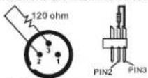
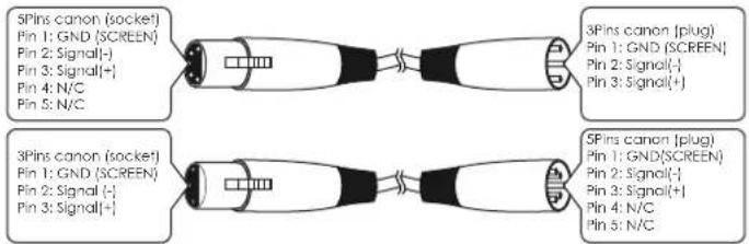
If you wish to connect DMX-controllers with other XLR-outputs, you need to use adapter-cables.
The transform of the controller line of 3 pins and 5 pins (plug and socket)
4.3 DMX Dipswitch Quick Reference Chart
| DMX Address Quick Reference Chart | |||||||||||||||||||
| Dip Switch Position | |||||||||||||||||||
| DMX DIP SWITCH SET0=OFF 1=ONX=OFFForON | #9 | 0 | 0 | 0 | 0 | 0 | 0 | 0 | 1 | 1 | 1 | 1 | 1 | 1 | 1 | 1 | |||
| #8 | 0 | 0 | 0 | 0 | 1 | 1 | 1 | 1 | 0 | 0 | 0 | 1 | 1 | 1 | 1 | ||||
| #7 | 0 | 0 | 1 | 1 | 0 | 0 | 1 | 1 | 0 | 1 | 1 | 0 | 0 | 1 | 1 | ||||
| #6 | 0 | 1 | 0 | 1 | 0 | 1 | 0 | 1 | 0 | 1 | 0 | 1 | 0 | 1 | 0 | ||||
| #1 | #2 | #3 | #4 | #5 | |||||||||||||||
| 0 | 0 | 0 | 0 | 32 | 64 | 96 | 128 | 160 | 192 | 224 | 256 | 188 | 320 | 352 | 384 | 416 | 448 | ||
| 1 | 0 | 0 | 0 | 1 | 33 | 65 | 97 | 129 | 161 | 193 | 225 | 257 | 189 | 321 | 353 | 385 | 417 | 449 | |
| 0 | 1 | 0 | 0 | 2 | 34 | 66 | 98 | 130 | 162 | 194 | 226 | 258 | 290 | 322 | 354 | 386 | 418 | 450 | |
| 1 | 1 | 0 | 0 | 3 | 35 | 67 | 99 | 131 | 163 | 195 | 227 | 259 | 291 | 323 | 355 | 387 | 419 | 451 | |
| 0 | 0 | 1 | 0 | 4 | 36 | 68 | 100 | 132 | 164 | 196 | 228 | 260 | 292 | 324 | 356 | 388 | 420 | 452 | |
| 1 | 0 | 1 | 0 | 5 | 37 | 69 | 101 | 133 | 165 | 197 | 229 | 261 | 293 | 325 | 357 | 389 | 421 | 453 | |
| 0 | 1 | 1 | 0 | 6 | 38 | 70 | 102 | 134 | 166 | 198 | 230 | 262 | 294 | 326 | 358 | 390 | 422 | 454 | |
| 1 | 1 | 1 | 0 | 7 | 39 | 71 | 103 | 135 | 167 | 199 | 231 | 263 | 295 | 327 | 359 | 391 | 423 | 455 | |
| 0 | 0 | 0 | 1 | 8 | 40 | 72 | 104 | 136 | 168 | 200 | 232 | 264 | 296 | 328 | 360 | 392 | 424 | 456 | |
| 1 | 0 | 0 | 1 | 9 | 41 | 73 | 105 | 137 | 169 | 201 | 233 | 265 | 297 | 329 | 361 | 393 | 425 | 457 | |
| 0 | 1 | 0 | 1 | 10 | 42 | 74 | 106 | 138 | 170 | 202 | 234 | 266 | 298 | 330 | 362 | 394 | 426 | 458 | |
| 1 | 1 | 0 | 1 | 11 | 43 | 75 | 107 | 139 | 171 | 203 | 235 | 267 | 299 | 331 | 363 | 395 | 427 | 459 | |
| 0 | 0 | 1 | 1 | 12 | 44 | 76 | 108 | 140 | 172 | 204 | 236 | 268 | 300 | 332 | 364 | 396 | 428 | 460 | |
| 1 | 0 | 1 | 1 | 13 | 45 | 77 | 109 | 141 | 173 | 205 | 237 | 269 | 301 | 333 | 365 | 397 | 429 | 461 | |
| 0 | 1 | 1 | 1 | 14 | 46 | 78 | 110 | 142 | 174 | 206 | 238 | 270 | 302 | 334 | 366 | 398 | 430 | 462 | |
| 1 | 1 | 1 | 1 | 15 | 47 | 79 | 111 | 143 | 175 | 207 | 239 | 271 | 303 | 335 | 367 | 399 | 431 | 463 | |
1. Before you begin
1.1 What are included
1) DMX-512 Controller
2) DC 9-12V 500mA, 90V\~240V Power Adapter
3) Manual
4) LED gooseneck lamp
1.2 Unpacking Instructions
Immediately upon receiving a fixture, carefully unpack the carton, check the contents to ensure that all parts are present, and have been received in good condition. Notify the shipper immediately and retain packing material for inspection if any parts appear damaged from shipping or the carton itself shows signs of mishandling. Save the carton and all packing materials. In the event that a fixture must be returned to the factory, it is important that the fixture be returned in the original factory box and packing.
1.3 Safety Instructions
Please read these instructions carefully, which includes important information about the installation, usage and maintenance.
- Please keep this User Guide for future consultation. If you sell the unit to another user, be sure that they also receive this instruction booklet.
• Always make sure that you are connecting to the proper voltage and that the line voltage you are connecting to is not higher than that stated on decal or rear panel of the fixture.
• This product is intended for indoor use only! - To prevent risk of fire or shock, do not expose fixture to rain or moisture. Make sure there are no flammable materials close to the unit while operating.
- The unit must be installed in a location with adequate ventilation, at least 50cm from adjacent surfaces. Be sure that no ventilation slots are blocked.
• Always disconnect from power source before servicing or replacing lamp or fuse and be sure to replace with same lamp source. - In the event of serious operating problem, stop using the unit immediately. Never try to repair the unit by yourself. Repairs carried out by unskilled people can lead to damage or malfunction. Please contact the nearest authorized technical assistance center. Always use the same type spare parts.
- Don't connect the device to a dimmer pack.
- Make sure power cord is never crimped or damaged.
- Never disconnect power cord by pulling or tugging on the cord.
- Do not operate this device under 113^ F ambient temperature conditions.
2. INTRODUCTION
2.1 Features
• DMX512/1990 Standard
• Controls 24 intelligent lights of up to 16 channels, totally 384 channels
• 30 banks, each with 8 scenes; 6 chose, each with up to 240 scenes
- Record up to 6 chases with fade lime and speeds
• 16 sliders for direct control of channels
• MIDI control over banks, chases and blackout

Control 384
USER'S
MANUAL
• Built-in microphone for music mode
- Auto mode program controlled by fade time sliders *DMX in/out: 3pinXRL
• LED gooseneck lamp
- Plastic end housing
2.2 General Overview
• The Controller is a universal intelligent lighting controller. It allows the control of 24 fixtures composed of 16 channels each and up to 240 programmable scenes. Six chase banks can contain up to 240 steps composed of the saved scenes and in any order. Programs can be triggered by music, midi, automatically or manually. All chases can be executed at the same time.
- On the surface you will find various programming tools such as 16 universal channel sliders, quick access scanner and scene buttons, and an LED display indicator for easier navigation of controls and menu functions.
2.3 Product Overview (front)
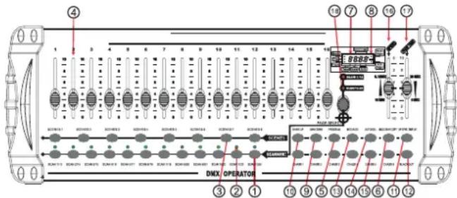
| Item | Button or Fader | Function |
| 1 | Scanner select buttons | Fixture selection |
| 2 | Scanner indicator LEDS | Indicates the fixtures currently selected |
| 3 | Scene select buttons | Universal bump buttons representing scene location for storage and selection |
| 4 | Channel factors | For adjusting cJMX values, Ch. 1-16 can be adjusted immediately after pressing the respective scanner select button |
| 5 | Program button | Used to enter programming mode |
| 6 | Music/bank Copy button | Used to activate Music mode and as the copy command during programming |
| 7 | LED display window | Status window displays pertinent operational data |
| 8 | Mode indicator LEDS | Provides operating mode status, [manual, music or audio] |
| 9 | Bank Up button | Function button to traverse Scene/ Steps in banks or chases |
| 10 | Bank Down button | Function button to Traverse Scene/ Steps in banks or chases |
| 11 | Top Display button | Sets the chase speed by lapping, and toggles between values and percentages |
| 12 | Blackout button | Sets the shutter or dinner value of all Fixtures to "B" causing all light output to cease |
| 13 | Midi/ADD button | Activates MIDI external control and also used to confirm the record/save process |
| 14 | Auto/Del button | Used to activate Auto mode and as the delete function key during programming |
| 15 | Chaser buttons | Chase memory 1 -6 |
| 16 | Speed factor | This will adjust the hold time of a scene or a stop within a chase |
| 17 | Fade-time folder | Also considered a cross-tode, sets the interval time between two scenes in a chase |
| 18 | Page select button | In manual mode, press to toggle between pages of control |
| MIDI NOTE | FUNCTION (TURN ON/OFF) |
| 00 to 07 | Scenes 1~8in BANK 1 |
| 08 to 15 | Scenes 1~8in BANK 2 |
| 16 to 23 | Scenes 1~8 in BANK 3 |
| 24 to 31 | Scenes 1~8in BANK 4 |
| 32 to 39 | Scenes 1~8 in BANK 5 |
| 40 to 47 | Scenes 1~8 in BANK6 |
| 48 to 55 | Scenes 1~8 in BANK 7 |
| 56 to 63 | Scenes 1~8 in BANK 8 |
| 64 to 71 | Scenes 1~8 in BANK 9 |
| 72 to 79 | Scenes 1~8in BANK 10 |
| 80 to 87 | Scenes 1~8 in BANK 11 |
| MIDI NOTE | FUNCTION (TURN ON/OFF) |
| 00 to 07 | Scenes 1~8in BANK 12 |
| 08 to 15 | Scenes 1~8 in BANK 13 |
| 16 to 23 | Scenes 1~8in BANK 14 |
| 24 to 31 | Scenes 1~8 in BANK 15 |
| 32 to 39 | Chase 1 |
| 40 to 47 | Chase 2 |
| 48 to 55 | Chase 3 |
| 56 to 63 | Chase 4 |
| 64 to 71 | Chase 5 |
| 72 to 79 | Chase 6 |
| 80 to 87 | BLACKOUT |
4. APPENDIX
4.1 DMX Primer
There are 512 channels in a DMX-512 connection. Channels may be assigned in any manner. A fixture capable of receiving DMX 512 will require one or a number of sequential channels. The user must assign a starting address on the fixture that indicates the first channel reserved in the controller. There are many different types of DMX controllable fixtures and they all may vary in the total number of channels required. Choosing a start address should be planned in advance. Channels should never overlap. If they do, this will result in erratic operation of the fixtures whose starting address is set incorrectly. You can however, control multiple fixtures of the same type using the same starting address as long as the intended result is that of unison movement or operation. In other words, the fixtures will be slaved together and all respond exactly the same.
DMX fixtures are designed to receive data through a serial Daisy Chain. A Daisy Chain connection is where the DATA OUT of one fixture connects to the DATA IN of the next fixture. The order in which the fixtures are connected is not important and has no effect on how a controller communicates to each fixture. Use an order that provides for the easiest and most direct cabling. Connect fixtures using shielded two conductor twisted pair cable with three pin XLR male to female connectors. The shield connection is pin 1, while pin 2 is Data Negative (S-) and pin 3 is Data positive (S+).
4.2 Fixture Linking
Occupation of the XLR-connection:
DMX-OUTPUT
XLR mounting-socket:
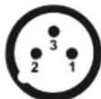
1- Ground
2- Signal (-)
3- Signal (+)
DMX-OUTPUT
XLR mounting-plug:
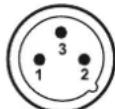
1-Ground
2- Signal (-)
3- Signal (+)
Caution: At the last fixture, the DMX-cable has to be terminated with a terminator. Solder a 1200 resistor between Signal (-) and Signal (+) into a 3-pin XLR plug and plug it in the DMX-output of the last fixture.
AUDIBAX | Control 384
USER'S MANUAL
Notes:
When deleting a scene the physical location is not removed, however, all 192 DMX channels available to the scene will be set to value 0.
3.5.4 Delete All Scenes
Action:
1) Press and hold the PROGRAM button and the BANK DOWN button while turning off power to the controller.
2) Turn the controller back on.
Notes:
CAUTION! This process is irreversible. All scenes with data will be set to 0.
3.6 Playback
1) Press the MUSIC BANK COPY button until the MUSIC LED turns on.
2) Select the program BANK to run in sound active mode using the BANK UP /DOWN buttons.
3) Alternatively you can press a single CHASE button (1-6) or several CHASE buttons in sequence and all selected chases will loop in the order selected.
4) You can adjust the duration time using the FADE TIME fader.
Notes:
In the Sound mode, programs will be triggered by the sound using its built-in microphone. Multiple chases selected will loop and run in the order originally selected.
3.6.2 Running In Auto-Mode
Action:
1) Press the AUTO DEL button until the AUTO LED turns on.
2) If a CHASE button is not pressed the controller will automatically run a BANK program
3) Change BANK programs by using BANKUP/DOWN buttons.
4) Alternatively you can press a single CHASE button (1\~6) or several CHASE buttons in sequence and all selected chases will loop in the order selected.
5) You can adjust the time between steps by moving the SPEED fader and the duration of the step by moving the FADE TIME fader.
Notes:
In the Auto mode, programs will be triggered by controllers fade and speed time as set on the faders. Multiple chases selected will loop and run in the order originally selected.
3.6.3 Blackout
The Blackout button brings all lighting output to 0 or off.
3.7 Midi Operation
The controller will only respond to MIDI commands on the MIDI channel which it is set to full stop. All MIDI control is performed using Note on commands. All other MIDI instructions are ignored. To stop a chase, send the blackout on note.
Action:
1) Press and hold the MIDI/ADD button for about 3 seconds
2) Select the MIDI control channel (1-16) via the BANK UP/DOWN buttons to set.
3) Press and hold the MIDI/ADD button for 3 seconds to save settings.
4) To release MIDI control, press any other button except the BANK buttons during
Notes: This is the Channel that the controller will receive MIDI note commands.
2.4 Product Overview (rear panel)
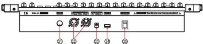
| Item | Button or Fader | Function |
| 21 | MIDI input port | For external triggering of Banks and Chases using a MIDI device |
| 22 | DMX output connector | DMX control signal |
| 23 | DC Input jack | Main power feed |
| 24 | USB Lamp socket | |
| 25 | ON/OFF power switch | Turns the controller on and off |
2.5 Common Terms
The following are common terms used in intelligent light programming. Blackout is a state by where all lighting fixtures light output are set to 0 or off, usually on a temporary basis.
DMX-512 is an industry standard digital communication protocol used in entertainment lighting equipment. For more information, read Sections
"DMX Primer" and "DMX Control Mode" in the Appendix.
Fixture refers to your lighting instrument or other device such as a fogger or dimmer of which you can control.
Programs are a bunch of scenes stacked one after another. It can be programmed as either a single scene or multiple scenes in sequence. Scenes are static lighting states.
Sliders also known as faders.
Chases can also be called programs. A chase consists of a bunch of scenes stacked one after another.
Scanner refers to a lighting instrument with a pan and tilt mirror; however, in the ILS-CON controller it can be used to control any DMX-512 compatible device as a generic fixture. MIDI is a standard for representing musical information in a digital format. A MIDI input would provide external triggering of scenes using midi device such as a midi keyboard.
Stand Alone refers to a fixture, s ability to function independently of an external controller and usually in sync to music, due to a built in microphone. Fade slider is used to adjust the time between scenes within a chase.
Speed slider affects the amount of time a scene will hold its state. It is also considered a wait time.
Shutter is a mechanical device in the lighting fixture that allows you to block the lights path. It is often used to lessen the intensity of the light output and to strobe.
Patching refers to the process of assigning fixtures a DMX channel or. Playbacks can be either scenes or chases that are directly called to execution by the user. A playback can also be considered program memory that can be recalled during a show.

Control 384
USER'S
MANUAL
3. OPERATING INSTRUCTIONS
3.1 Setup
3.1.1 Setting Up The System
1) Plug the AC to DC power supply to the system back panel and to the mains outlet. 2) Plug in your DMX cable(s) to your intelligent lighting as described in the fixtures respective manual. For a quick Primer on DMX see the "DMX Primer" section in the Appendix of this manual.
3.1.2 Fixture Addressing
The Controller is programmed to control 32 channels of DMX per fixture, therefore the fixtures you wish to control with the corresponding "SCANNER" buttons on the unit, must be spaced 16 channels apart.
| FIXTURE OR SCANNER# | DEFAULT DMX STARTING ADDRESS | BINARYDIPSWITCH SETTINGS TO THE "ONPOSITION" |
| 1 | 1 | 1 |
| 2 | 17 | 1,5 |
| 3 | 33 | 1,6 |
| 4 | 49 | 1,5,6 |
| 5 | 65 | 1,7 |
| 6 | 81 | 1,5,7 |
| 7 | 97 | 1,6,7 |
| 8 | 113 | 1,5,6,7 |
| 9 | 129 | 1,8 |
| 10 | 145 | 1,5,8 |
| 11 | 161 | 1,6,8 |
| 12 | 177 | 1,5,6,8 |
| FIXTURE OR SCANNER# | DEFAULT DMX STARTING ADDRESS | BINARYDIPSWITCH SETTINGS TO THE "ONPOSITION" |
| 13 | 193 | 1,7,8 |
| 14 | 209 | 1,5,7,8 |
| 15 | 225 | 1,6,7,8 |
| 16 | 241 | 1,5,6,7,8 |
| 17 | 257 | 1,9 |
| 18 | 273 | 1,5,9 |
| 19 | 289 | 1,6,9 |
| 20 | 305 | 1,5,6,9 |
| 21 | 321 | 1,7,9 |
| 22 | 337 | 1,5,7,9 |
| 23 | 353 | 1,6,7,9 |
| 24 | 369 | 1,5,6,7,9 |
Please refer to your individual fixture's manual for DMX addressing instructions. The table above refers to a standard 9 dipswitch binary configurable device.
3.1.3 Pan and Tilt Channels
Because not all intelligent lighting fixtures are alike or share the same control attributes. The Controller allows the user to assign the wheel the correct pan and tilt channel for every individual fixture.
Action:
1) Press and hold PROGRAM & TAPSYNC different DMX cannel.
Faders are given a channel buttons together (1) time to access the number and are labeled on the surface of the channel as signment mode.
2) Press a SCANNER button or PAGE SELECT button that represents the fixture whose faders you would like to reassign
3) Move one fader of 16 channels to select the pan cannel.
4) Press the TAPSYNC DISPLAY button to select pan / tilt.
5) Move one fader of 16 channel to select the tilt cannel
6) Press and hold PROGRAM & APSYNC DISPLAY buttons to exit and save setting. All LEDs will blink
3.4.8 Delete A Chase
Action:
1) Press and hold the PROGRAM button to enter programming mode
2) Press the CHASE button (1\~6) to be deleted
3) Press and hold AUTO DEL button and the respective CHASE button to delete the chase. All LEDs will blink.
3.4.9 Delete All Chase Programs
CAUTION! This procedure will result in irrevocable loss of chase step memory. The individual scenes and program banks will be preserved.
Action:
1) Turn OFF controller
2) Press and hold the BANK DOWN button and the AUTO DEL button while turning ON the controller.
3) All LEDs will blink.
3.5 Scene Programming (Steps)
3.5.1 Insert a Scene
Action:
1) Press and hold the PROGRAM button to enter programming mode
2) Press the desired CHASE button
3) Press the TAPSYNC DISPLAY to switch the LED display to steps view
4) Use the BANKUP/DOWN buttons to navigate steps and locate the insert point of the new
The display will read the step number
5) Press MIDI/ADD button to prepare the insert
6) Use the BANKUP/DOWN button to locate the SCENE
7) Press the SCENE button that corresponds to the scene to be inserted
8) Press MIDI/ADD button to insert the scene. All LEDs will blink.
scene
Notes:
/.e. To insert a scene between Steps 05 and 06 navigate using BANK buttons until the display reads STEP05.
3.5.2 Copy a Scene
Action:
1) Press and hold the PROGRAM button to enter programming mode
2) Select the BANK that contains the scene to be copied using the BANK UP/DOWN buttons
3) Press the SCENE button that corresponds to the scene to be copied
4) Press MIDI/ADD button to copy the scene
5) Select the destination BANK that contains the scene memory to record onto using the BANKUP/DOWN buttons
6) Press the desired SCENE button to complete copy. All LEDs will blink
3.5.3 Delete a Scene
Action:
1) Press and hold the PROGRAM button to enter programming mode.
2) Select the BANK that contains the scene to be deleted by using the BANK UP/ DOWN
3) Press and hold the AUTO DEL button.
4) Press the SCENE button that corresponds to the scene you want to delete. All LEDs will
buttons.
blink.

Control 384
3.4.2 Running AChase
Action:
1) Press a CHASE button then press the AUTO DEL button.
2) Adjust the Chase speed by tapping the TAPSYNC DISPLAY button twice at a rate of your choosing.
Notes: The time between 2 taps will set the chase speed (up to 10 minutes)
3.4.3 Checking A Chase
Action:
1) Press and hold the PROGRAM button until the LED is light.
2) Select the desired CHASE button.
3) Press the TAPSYNC DISPLAY button to switch the LED display to steps.
4) Review each scene/step individually by using the BANK UP/DOWN buttons.
3.4.4 Edit Chase (Copy Bank Into Chase)
Action:
1) Press and hold the PROGRAM button Notes to enter programming mode.
2) Press the desired CHASE button.
3) Select the BANK to be copied using the BANK UP/DOWN buttons.
4) Press MUSIC/BANK COPY button to prepare copy.
5) Press MIDI/ADD button to copy the bank. All LEDs will blink.
3.4.5 Edit Chase (Copy Scene Into Chase)
Action:
1) Press and hold the PROGRAM button to enter programming mode.
2) Press the desired CHASE button
3) Select the BANK that contains the scene to be copied using the BANK UP/DOWN buttons.
4) Press the SCENE button that corresponds to the scene to be copied.
5) Press MIDI/ADD button to copy the scene. All LEDs will blink.
3.4.6 Edit Chase (Insert Scene Into A Chase)
Action:
1) Press and hold the PROGRAM button to enter programming mode
2) Press the desired CHASE button
3) Press the TAPSYNC DISPLAY to switch the LED display to steps view
4) Use the BANK UP/DOWN buttons to navigate steps and locate the insert point of the new scene. The display will read the step number.
5) Press MIDI/ADD button to prepare the insert
6) Use the BANK UP/DOWN button to locate the SCENE
7) Press the SCENE button that corresponds to the scene to be inserted
8) Press MIDI/ADD button to insert the scene. All LEDs will blink
Notes:
/.e. To insert a scene between Steps 05 and 06 navigate using BANK buttons until the display reads STEP05.
3.4.7 Delete a Scene in a Chase
Action:
1) Press and hold the PROGRAM button to enter programming mode
2) Press the desired CHASE button that contains the scene to be deleted
3) Press the TAPSYNC DISPLAY button to switch the LED display to steps
4) Select the scene/step to be deleted using the BANK UP/DOWN buttons
5) Press AUTO DEL button to delete the step/scene. All LEDs will blink
USER'S
MANUAL
Notes:
All pan/tilt can be reassigned to output on a different DMX channel.
Press AUTO/DEL buttons to delete the channel assignment mode.
All pan/tilt can be reassigned to output on a different DMX channel.
3.1.4 Resetting The System
Warning:
This will reset the controller to its factory defaults.
This will erase all programs and settings.
Action:
1) Turn off the unit.
2) Press and hold BANK UP and AUTO/DEL
Turn on power to the unit (while still holding BANK UP and AUTO/DEL).
3.1.5 Copy Scanner
Example: Copying Scanner 1 into Scanner 2
Action:
1) Press and hold SCANNER button # 1.
2) While holding button # 1 press SCANNER button #2.
3) Release SCANNER button # 1 first before releasing SCANNER button # 2.
4) All SCANNER LED indicators will flash to confirm successful copy.
Notes:
To save time, you can copy the settings of one Scanner button to another.
3.1.6 Fade Time Assign
You can choose whether the board's fade time during scene execution is implemented broadly to all output channels or only to the Pan & Tilt movement channels. This is relevant because often you will want gobos and colors to change quickly while not affecting the movement of the light.
Action:
1) Turn OFF the controller.
2) Hold the BLACKOUT and TAPSYNC
DISPLAY buttons simultaneously.
3) Turn ON the controller.
4) Press the TAPSYNC DISPLAY button to toggle between the two modes. Either all channels
(A) or select channel Pan & Tilt only (P)
5) Press BLACKOUT and TAPSYNC DISPLAY to save settings. All LEDs will blink to confirm.
Notes:
A: All channels
P: Only Pan & Tilt
3.2 Operation
3.2.1 Manual Mode
The manual mode allows direct control of all scanners. You are able to move them and change attributes by using the channel faders.
Action:
1) Press the AUTO DEL button repeatedly until the MANUAL LED is lit.
2) Selects SCANNER button.
3) Move faders to change fixture attributes.
TAPSYNC DISPLAY button:
Press to toggle the output indicator on the LED display between DMX values (0-255) and percentage (0-100)

Control 384
USER'S
MANUAL
Notes:
All changes made while in Manual Mode are temporary and will not be recorded.
3.2.2 Review Scene Or Chase
This instruction assumes that you have already recorded scenes and chases on the controller. Otherwise skip section and go to programming.
Action: (Scene Review)
1) Select any one of the 30 banks by pressing the BANK UP/DOWN buttons.
2) Select a SCENE button (1 \~8) to review.
3) Move wheel and faders to change fixture attributes.
Action: (Chase Review)
1) Press anyone of the 6 CHASE buttons.
2) Press the TAP DISPLAY button to view the step number on the display.
3) Press the BANK UP/DOWN buttons review all scenes in the chase.
Notes:
Make sure you are still in MANUAL Mode.
3.3 Programming
A program (bank) is a sequence of different scenes (or steps) that will be called up one after another. In the controller 30 programs can be created of 8 scenes in each.
3.3.1 Entering Program Mode
1) Press the Program button until the LED blinks.
3.3.2 Create A Scene
A scene is a static lighting state. Scenes are stored in banks. There are 30 bank memories on the controller and each bank can hold 8 scene memories. The controller can save 240 scenes total.
Action:
1) Press the PROGRAM button until the LED blinks.
2) Position SPEED and FADE TIME sliders all the way down.
3) Select the SCANNERS you wish to include in your scene.
4) Compose a look by moving the sliders and wheel.
Tap MIDI/REC button.
5) Choose a BANK (01-30) to change if necessary.
6) Select a SCENES button to store.
7) Repeat steps 3 through 7 as necessary. 8 scenes can be recorded in a Program.
8) To exit program mode, hold the PROGRAM button.
Notes:
Deselect Blackout if LED is lit.
You can select more than one fixture.
There are 8 scenes available in every bank.
All LEDs will flash to confirm. The LED display will now indicate the Scene number and Bank number used.
3.3.3 Running A Program
Action:
1) Use BANKUP/DOWN buttons to change Program banks if necessary.
2) Press the AUTO DEL button repeatedly until the AUTO LED turns on.
3) Adjust the PROGRAM speed via the SPEED fader and the loop rate via the FADE TIME fader.
4) Alternatively you can tap the TAPSYNC DISPLAY button twice. The time between two taps sets the time between SCENES (up to 10 minutes).
Notes:
Deselect Blackout if LED is lit.
Also called a Tap-Sync.
3.3.4 Check Program
Action:
1) Press and hold the PROGRAM button until the LED blinks.
2) Use the BANK UP/DOWN buttons to select the PROGRAM bank to review.
3) Press the SCENES buttons to review each scene individually.
3.3.5 Editing A Program
Scenes will need to be modified manually.
Action:
1) Press and hold the PROGRAM button until the LED blinks.
2) Use BANK UP/DOWN buttons to change Program banks if necessary.
3) Select the desired fixture via the SCANNERS button.
4) Adjust and change fixture attributes using the channel faders and wheel.
5) Press the MIDI/ADD button to prepare the save.
6) Select the desired SCENES button to save.
Notes:
Deselect Blackout if LED is lit.
3.3.6 Copy A Program
Action:
1) Press and hold the PROGRAM button until the LED blinks.
2) Use BANK UP/DOWN buttons to select the PROGRAM bank you will copy.
3) Press the MIDI/ADD button to prepare the copy.
4) Use BANK UP/DOWN buttons to select the destination PROGRAM bank.
5) Press the MUSIC BANK COPY button to execute the copy. All LEDs on the controller will
blink.
Notes:
All 8 scenes in a Program bank will be copied.
3.4 Chase Programming
A chase is created by using previously created scenes. Scenes become steps in a chase and can be arranged in any order you choose. It is highly recommended that prior to programming chases for the first time; you delete all chases from memory. See "Delete All Chases" for instructions.
3.4.1 Create A Chase
A Chase can contain 240 scenes as steps. The term steps and scenes are used interchangeably.
Action:
1) Press the PROGRAM button until the LED blinks.
2) Press the CHASE (1 \~6) button you wish to program.
3) Change BANK if necessary to locate a scene.
4) Select the SCENE to insert.
5) Tap the MIDI/ADD button to store.
6) Repeat steps 3 - 5 to add additional steps in the chase. Up to 240 steps can be recorded.
7) Press and hold the PROGRAM button to save the chase.

Control 384
MANUAL DE USUARIO
- Technical Specifications
- Contents
- Before you begin
- Installation
- Operating instructions
- SETUP
- OPERATION
- PROGRAMMING
- CHASE PROGRAMMING
- SCENE PROGRAMMING (STEPS)
- PLAYBACK
- What are included
- Unpacking Instructions
- Safety Instructions
- INTRODUCTION
- Features
- Control 384
- General Overview
- APPENDIX
- DMX Primer
- Fixture Linking
- AUDIBAX | Control 384
- Notes:
- Delete All Scenes
- Action:
- Running In Auto-Mode
- Blackout
- Midi Operation
- Product Overview (rear panel)
- Common Terms
- Setting Up The System
- Fixture Addressing
- Pan and Tilt Channels
- Delete A Chase
- Delete All Chase Programs
- Insert a Scene
- scene
- Copy a Scene
- Delete a Scene
- buttons.
- blink.
- Running AChase
- Checking A Chase
- Edit Chase (Copy Bank Into Chase)
- Edit Chase (Copy Scene Into Chase)
- Edit Chase (Insert Scene Into A Chase)
- Delete a Scene in a Chase
- Resetting The System
- Warning:
- Copy Scanner
- Fade Time Assign
- Manual Mode
- TAPSYNC DISPLAY button:
- Review Scene Or Chase
- Action: (Scene Review)
- Action: (Chase Review)
- Entering Program Mode
- Create A Scene
- Running A Program
- Check Program
- Editing A Program
- Copy A Program
- Create A Chase
Brand : Audibax
Model : Control 384
Category : Uncategorized