
CTP2056 - Router Juniper - Free user manual and instructions
Find the device manual for free CTP2056 Juniper in PDF.


| Product Type | Circuit to Packet (CTP) Router |
| Model | CTP2056 |
| Brand | Juniper Networks |
| Dimensions (H x W x D) | 7.0 in. (17.8 cm) x 17.25 in. (43.81 cm) x 11.25 in. (28.57 cm) |
| Weight (Chassis Only) | 27 lb (12.25 kg) |
| AC Power Input | 100–240 VAC, 50-60 Hz, 2.5 A, 250 W |
| DC Power Input | -40 to -72 VDC, 4 A @ -48 VDC, 192 W; redundant input feeds |
| Interface Module Slots | 7 removable interface modules |
| Processor Module Slots | 1 removable processor module |
| Supported Interface Modules | Serial (8-port), T1/E1 (8-port), Compression, Compression 2 High Density, 4WE&M, 2W-FXS/FXO, 8P-IRIG, Clock modules |
| Ethernet Connectivity | 1 Gbps Ethernet via RJ-45 |
| Management Ports | Console (USB or RJ-45), Ethernet management |
| Operating System | CTPOS (Circuit to Packet Operating System) |
| Environmental Operating Temperature | 32° to 104° F (0° to 40° C) |
| Operating Humidity | 5% to 90% (noncondensing) |
| Airflow | Side-to-side; front intake, rear exhaust |
| Hot-Swap Support | Interface modules (except slot 0) can be hot-swapped |
| Fan Trays | Removable fan tray with air filter |
| Safety Certifications | UL 60950-1, EN 60950-1, IEC 60950-1, AS/NZS 60950, CAN/CSA C22.2, Low Voltage Directive, FCC Part 15 Class A, EN55022 Class A |
| Maintenance | Clean air vents with dry cloth; replace fan trays; use ESD strap when handling components |
Frequently Asked Questions - CTP2056 Juniper
User questions about CTP2056 Juniper
0 question about this device. Answer the ones you know or ask your own.
Ask a new question about this device
Download the instructions for your Router in PDF format for free! Find your manual CTP2056 - Juniper and take your electronic device back in hand. On this page are published all the documents necessary for the use of your device. CTP2056 by Juniper.
USER MANUAL CTP2056 Juniper
CTP2000 Hardware Documentation
Modified: 2015-07-27
Juniper Networks, Inc.
1133 Innovation Way
Sunnyvale, California 94089
USA
408-745-2000
www.juniper.net
Copyright © 2015, Juniper Networks, Inc. All rights reserved.
Juniper Networks, Junos, Steel-Belted Radius, NetScreen, and ScreenOS are registered trademarks of Juniper Networks, Inc. in the United States and other countries. The Juniper Networks Logo, the Junos logo, and JunosE are trademarks of Juniper Networks, Inc. All other trademarks, service marks, registered trademarks, or registered service marks are the property of their respective owners.
Juniper Networks assumes no responsibility for any inaccuracies in this document. Juniper Networks reserves the right to change, modify, transfer, or otherwise revise this publication without notice.
CTP2000 Hardware Documentation
Copyright © 2015, Juniper Networks, Inc.
All rights reserved.
The information in this document is current as of the date on the title page.
YEAR 2000 NOTICE
Juniper Networks hardware and software products are Year 2000 compliant. Junos OS has no known time-related limitations through the year 2038. However, the NTP application is known to have some difficulty in the year 2036.
END USER LICENSE AGREEMENT
The Juniper Networks product that is the subject of this technical documentation consists of (or is intended for use with) Juniper Networks software. Use of such software is subject to the terms and conditions of the End User License Agreement ("EULA") posted at http://www.juniper.net/support/eula.html. By downloading, installing or using such software, you agree to the terms and conditions of that EULA.
Table of Contents
About the Documentation ...... Documentation and Release Notes ...... Documentation Conventions ...... Documentation Feedback ...... Requesting Technical Support ...... Self-Help Online Tools and Resources ...... Opening a Case with JTAC ....
Part 1 Overview
Chapter 1 CTP2000 Series Platform Overview Introducing CTP Platforms CTP2008 Platform CTP2024 Platform CTP2056 Platform
Chapter 2 CTP2000 Series Interface Modules CTP2000 Serial Interface Modules CTP2000 T1/E1 Interface Module CTP2000 Compression Interface Module CTP2000 Compression 2 High Density Interface Module CTP2000 4WE&M Interface Module Supervisory Signaling CTP2000 2W-FXS and 2W-FXO Interface Modules Required Cables and Pinouts Analog FXS/FXO Loop-Start Signaling Answer Supervision Disconnect Supervision Analog FXS/FXO Ground-Start Signaling Digital Signaling Digital FXS/FXO Loop-Start Signaling Digital FXS/FXO Ground-Start Signaling CTP2000 8P-IRIG Interface Module CTP2000 Clock Interface Modules External Reference Clock Installation Notes for Clock Interface Modules
Part 2 Planning
Chapter 3 System Specifications....29 CTP2008 Platform Specifications and Certification ...... CTP2024 Platform Specifications and Certification ...... .....
CTP2056 Platform Specifications and Certification
Chapter 4 Planning and Preparing the Site
Before You Install a CTP Platform
CTP2000 Environmental Requirements
Chapter 5 Equipment Rack Requirements
CTP2000 Rack Requirements
CTP2000 Mechanical Requirements
CTP2000 Space Requirements
CTP2000 Rack Installation
CTP Cabling Recommendations
Chapter 6 Cable and Pinout Specifications
CTP2000 4WE&M Interface Connector Pinouts
CTP2000 4WE&M RTM Connector A Pinouts
CTP2000 4WE&M Connector B Pinouts
CTP2000 FXS and FXO Interface Module Cables and Pinouts
Required Cables
RTM Pinout Locations
FXS Connector Pinouts
FXO Connector Pinouts
CTP2000 Series Console Cable Pinouts
CTP Fast Ethernet and Power Cables
Fast Ethernet Cables
DC Power Cables
Part 3 Safety
Chapter 7 General Safety Guidelines and Warnings
CTP Safety Guidelines and Warnings
Chapter 8 Module Installation Safety Guidelines and Warnings
Safety Guidelines and Warnings for Installing CTP Modules
Chapter 9 Hardware Compliance 55
Declaration of Conformity for CTP2000 Platforms
Federal Communications Commission (FCC) Statement 56
FCC Requirements for Consumer Products
Food and Drug Administration, Center for Devices and Radiological Health ..... 57
Compliance with Canadian Regulations
Industry Canada Notice
Industry Canada Notice CS-03
Canadian Department of Communications Explanatory Notes ..... 59
DOC Explanatory Notes: Equipment Attachment Limitations ..... 59
Contacting Juniper Networks
Chapter 11 Installing the Chassis....67
Before You Install the CTP2000 Platform . . . . . . . . . . . . . . . . . . . . . . . . . .
Installing the CTP2000 Platform in Freestanding Mode . . . . . . . . . . . . . . . . . .
Special Guidelines for Installing CTP2056 Chassis in a Rack . . . . . . . . . . . . . . . . . . . . .
Installing the CTP2000 Platform in a Rack . . . . . . . . . . . . . . . . . . . . . . . . . . .
Chapter 12 Installing Modules 71
CTP2000 Modules Installation Overview
Protecting CTP2000 Modules and Slots . . . . . . . . . . . . . . . . . . . . . . . . . . .
Required Tools and Safety Items for Installing CTP Modules . . . . . . . . . . . . . .
Installing a CTP Interface Module, Processor Module, or Clock Module ..... 73
Removing a CTP Interface Module, Processor Module, or Clock Module ..... 73
Installing or Removing a CTP2000 Series CompactFlash Card . . . . . . . . . . . . . . . . . . 7
Installing a PMC on CTP2000 Platforms . . . . . . . . . . . . . . . . . . . . . . . . . .
Chapter 13 Installing and Removing SFPs in a CTP Module . . . . . . . . . . . . . .
Installing SFPs in a CTP2000 Module . . . . . . . . . . . . . . . . . . . . . . . . . . . .
Removing SFPs in a CTP2000 Module . . . . . . . . . . . . . . . . . . . . . . . . . . . . .
Chapter 14 Upgrading Components for Memory Upgrades . . . . . . . . . . . . . . . . .
Upgrading CTP2000 Series Components for Memory Upgrades . . . . . . . . . . . . . 81
Chapter 15 Cabling 83
Cabling the CTP2000 Platform Overview . . . . . . . . . . . . . . . . . . . . . . . . . . . .
Required Tools, Wires, and Cables for the CTP2000 Platform . . . . . . . . . . . . . . . . &
CTP2000 Management Ports . . . . . . . . . . . . . . . . . . . . . . . . . . . . . . . .
Cabling a CTP2000 Interface Module . . . . . . . . . . . . . . . . . . . . . . . . . . . . .
Cabling the CTP Platform for DC Power . . . . . . . . . . . . . . . . . . . . . . . . . .
Task 1: Turning Off All CTP Platform Power . . . . . . . . . . . . . . . . . . . . . .
Task 2: Connecting the Grounding Cable to the CTP Platform (CTP2056
Platform Only)
Task 3: Connecting the Power Cables to the CTP2000 Platform ..... 86
Chapter 16 Powering On 89
Before You Power On the CTP2000 Platform . . . . . . . . . . . . . . . . . . . . . . . . . .
Powering On the CTP2000 Platform . . . . . . . . . . . . . . . . . . . . . . . . . . . . . .
Powering Off the CTP Platform . . . . . . . . . . . . . . . . . . . . . . . . . . . . . . .
Chapter 17 Accessing the CTP2000 Platform....93
Setting Up Management Access on the CTP2000 Platform . . . . . . . . . . . . . .
CTP2000 Console Port Setup . . . . . . . . . . . . . . . . . . . . . . . . . . . . .
Using HyperTerminal with the CTP2000 Platform . . . . . . . . . . . . . . . . . . . . .
Connecting Directly to the CTP2000 Platform . . . . . . . . . . . . . . . . . . . . . . . . . . . . .
CTP2000 Platform SSH Setup
Part 5 Maintenance
Chapter 18 Maintaining Components .....
Required Tools for Maintaining the CTP Platform . . . . . . . . . . . . . . . . . . . . . . .
Storing CTP Modules and Other Components . . . . . . . . . . . . . . . . . . . . . . .
Cleaning the CTP Platform
Replacing an AC Power Supply . . . . . . . . . . . . . . . . . . . . . . . . . . . . .
Chapter 19 Replacing Interface Modules Using Hot-Swap
CTP2000 Hot-Swap Interface Module Replacement ..... 10
Chapter 20 Product Reclamation and Recycling . . . . . . . . . . . . . . . . . . . . . . .
Product Reclamation and Recycling Program ....
Chapter 21 Replacing Fan Trays .... 107
Removing a CTP2000 Fan Tray . . . . . . . . . . . . . . . . . . . . . . . . . . . . . .
Installing a CTP2000 Fan Tray . . . . . . . . . . . . . . . . . . . . . . . . . . . . . . . . . . . . .
Chapter 22 Packing and Returning Hardware . . . . . . . . . . . . . . . . . . . . . . .
Return Procedure
Returning CTP Products for Repair or Replacement . . . . . . . . . . . . . . . . . . . .
Part 6 Troubleshooting
Chapter 23 Troubleshooting Power Failures . . . . . . . . . . . . . . . . . . . . . . . .
CTP Platform Does Not Power On . . . . . . . . . . . . . . . . . . . . . . . . . . . . .
CTP Platform Shuts Down
Chapter 24 Contacting Customer Support
Contacting Customer Support
Locating CTP Component Serial Numbers . . . . . . . . . . . . . . . . . . . . . . . . . . . . . .
Information You Might Need to Supply to JTAC . . . . . . . . . . . . . . . . . . . . . . . . . . . .
Part 7 Index
Index 119
List of Figures
Part 1 Overview
Chapter 1 CTP2000 Series Platform Overview
Figure 1: CTP2008 Chassis (AC and DC Version, Front View)
Figure 2: CTP2008 Platform (AC Version, Rear View)
Figure 3: CTP2008 Platform (DC Version, Rear View)
Figure 4: CTP2024 Chassis (AC and DC Version, Front View)
Figure 5: CTP2024 Platform (AC Version, Rear View)
Figure 6: CTP2024 Platform (DC Version, Rear View)
Figure 7: CTP2056 Chassis (AC and DC Version, Front View)
Figure 8: CTP2056 Platform (AC Version, Rear View)
Figure 9: CTP2056 Platform (DC Version, Rear View)
Chapter 2 CTP2000 Series Interface Modules . . . . . . . . . . . . . . . . . . . . . . .
Figure 10: Sample Serial Interface Module
Figure 11: CTP2000 IM-8P-T1/E1 Interface Module
Figure 12: Compression Interface Module
Figure 13: CTP2000 4WE&M Module
Figure 14: 4WE&M RTM....12
Figure 15: Jumper Locations on the RTM
Figure 16: Jumper Positions for Signaling Types
Figure 17: Analog 4WE&M Signaling Types
Figure 18: Front Panel of CTP2000 2W-FXS Interface Module .....
Figure 19: Rear Panel of CTP2000 2W-FXS RTM
Figure 20: Front Panel of CTP2000 2W-FXO Interface Module
Figure 21: Rear Panel of CTP2000 2W-FXO RTM
Figure 22: CTP2000 8P-IRIG Interface Module
Figure 23: Clock Main Module
Figure 24: Clock Spoke Module
Figure 25: Hub-and-Spoke Setup
Part 2 Planning
Chapter 6 Cable and Pinout Specifications . . . . . . . . . . . . . . . . . . . . . . . . .
Figure 26: RTM Pinouts for CTP2000 2W-FXS and 2W-FXO Interface Modules
Figure 27: CTP2000 Series Console Cable Pin Configurations for PP310 and PP332 Processors
Part 3 Safety
Chapter 9 Hardware Compliance .... 55
Figure 28: CTP2000 Declaration of Conformity
Part 4 Installation
Chapter 12 Installing Modules 71
Figure 29: CompactFlash on the RTM .....
Figure 30: CTP2000 Platforms PMC Location . . . . . . . . . . . . . . . . . . . . . .
Chapter 13 Installing and Removing SFPs in a CTP Module
Figure 31: Representative SFP
Figure 32: Possible Release Mechanisms on the SFP . . . . . . . . . . . . . . . . . . .
Part 5 Maintenance
Chapter 18 Maintaining Components .....
Figure 33: Replacing an AC Power Supply . . . . . . . . . . . . . . . . . . . . . . . . .
List of Tables
About the Documentation . . . . . . . . . . . . . . . . . . . . . . . . . . .
Table 1: Notice Icons....xii
Table 2: Text and Syntax Conventions
Part 1 Overview
Chapter 2 CTP2000 Series Interface Modules .....
Table 3: Jumper Positions for Configuring Port Signaling Type .....
Table 4: Signal Definitions .....
Table 5: Supported Signaling Types for the CTP2000 4WE&M Module ..... 17
Table 6: Ground-Start Signaling at FXO Interface for Call Initiated by the FXO Interface ..... 21
Table 7: Ground-Start Signaling at FXO Interface for Call Initiated by the FXS Interface 21
Table 8: Ground-Start Signaling at FXS Interface for Call Initiated by the FXS Interface....22
Table 9: Ground-Start Signaling at FXS Interface for Call Initiated by the FXO Interface....22
Part 2 Planning
Chapter 3 System Specifications....29
Table 10: CTP2008 Platform Specifications .....
Table 11: CTP2024 Platform Specifications .....
Table 12: CTP2056 Platform Specifications .....
Chapter 6 Cable and Pinout Specifications . . . . . . . . . . . . . . . . . . . . . . . . .
Table 13: CTP2000 4WE&M RTM Pinouts-Connector A . . . . . . . . . . . . . . . . . . .
Table 14: CTP2000 4WE&M RTM Pinouts-Connector B . . . . . . . . . . . . . . . . . .
Table 15: CTP2000 FXS Connector Pinouts on the RTM .....
Table 16: CTP2000 FXO Connector Pinouts on the RTM . . . . . . . . . . . . . . . . .
Table 17: CTP2000 Series Console Cable Pinouts for PP310 and PP332 Processors
Table 18: CTP2000 Series Console Cable Pinouts for the PP833 Processor . . . . 47
Part 4 Installation
Chapter 15 Cabling 83
Table 19: Required Cables .....
Table 20: CTP Power Supply Cables and Wires Needed .....
About the Documentation
- Documentation and Release Notes on page xi
• Documentation Conventions on page xi
• Documentation Feedback on page xiii - Requesting Technical Support on page xiv
Documentation and Release Notes
To obtain the most current version of all Juniper Networksal documentation, see the product documentation page on the Juniper Networks website at http://www.juniper.net/techpubs/.
If the information in the latest release notes differs from the information in the documentation, follow the product Release Notes.
Juniper Networks Books publishes books by Juniper Networks engineers and subject matter experts. These books go beyond the technical documentation to explore the nuances of network architecture, deployment, and administration. The current list can be viewed at http://www.juniper.net/books.
Documentation Conventions
Table 1 on page xii defines notice icons used in this guide.
Table 1: Notice Icons
| DescriptionMeaningIcon | ||
| Indicates important features or instructions.Informational note | ||
| Indicates a situation that might result in loss of data or hardware damage.Caution | ||
| Alerts you to the risk of personal injury or death.Warning | ||
| Alerts you to the risk of personal injury from a laser.Laser warning | ||
| Indicates helpful information.Tip | ||
| Alerts you to a recommended use or implementation.Best practice |
Table 2 on page xii defines the text and syntax conventions used in this guide.
Table 2: Text and Syntax Conventions
| ExamplesDescriptionConvention | ||
| Bold text like this | Represents text that you type. | To enter configuration mode, type theconfigure command:user@host>configure |
| Fixed-width text like this | Represents output that appears on theuser@host>show chassis alarms terminal screen.No alarms currently active | |
| Italic text like this | Introduces or emphasizes important new terms.Identifies guide names.Identifies RFC and Internet draft titles. | A policy term is a named structure that defines match conditions and actions.Junos OS CLI User GuideRFC 1997, BGP Communities Attribute |
| Italic text like this | Represents variables (options for whichConfigure the machine's domain name: you substitute a value) in commands or configuration statements.[edit]root@# set system domain-name domain-name | |
Table 2: Text and Syntax Conventions (continued)
| ExamplesDescriptionConvention | ||
| Text like this | Represents names of configuration statements, commands, files, and directories; configuration hierarchy levels; or labels on routing platform components. | To configure a stub area, include the stub statement at the [edit protocols ospf area area-id] hierarchy level.The console port is labeled CONSOLE. |
| < > (angle brackets) | Encloses optional keywords or variables. | stub; |
| | (pipe symbol) | Indicates a choice between the mutual exclusive keywords or variables on either side of the symbol. The set of choices (string1 | string2 | string3) often enclosed in parentheses for clarity. | |
| # (pound sign) | same line as the configuration statement to which it applies. | rsvp { # Required for dynamic MPLS only indicates same line as the configuration statement to which it applies. |
| [ ] (square brackets) | Encloses a variable for which you can substitute one or more values. | community name members [ community-ids ] |
| Indention and braces ( { } ) | Identifies a level in the configuration hierarchy. | [edit]routing-options {static {route default {nexthop address;retain;}]} |
| ; (semicolon) | Identifies a leaf statement at a configuration hierarchy level. | |
| GUI Conventions | ||
| Bold text like this | Represents graphical user interface (GUI) In the Logical Interfaces box, select items you click or select. | All Interfaces.To cancel the configuration, click Cancel. |
| > (bold right angle bracket) | Separates levels in a hierarchy of menu the configuration editor hierarchy, selections. | select Protocols>Ospf. |
Documentation Feedback
We encourage you to provide feedback, comments, and suggestions so that we can improve the documentation. You can provide feedback by using either of the following methods:
- Online feedback rating system—On any page at the Juniper Networks Technical Documentation site at http://www.juniper.net/techpubs/index.html, simply click the stars to rate the content, and use the pop-up form to provide us with information about your experience. Alternately, you can use the online feedback form at http://www.juniper.net/techpubs/feedback/.
- E-mail—Send your comments to techpubs-comments@juniper.net. Include the document or topic name, URL or page number, and software version (if applicable).
Requesting Technical Support
Technical product support is available through the Juniper Networks Technical Assistance Center (JTAC). If you are a customer with an active J-Care or Partner Support Service support contract, or are covered under warranty, and need post-sales technical support, you can access our tools and resources online or open a case with JTAC.
- JTAC policies—For a complete understanding of our JTAC procedures and policies, review the JTAC User Guide located at http://www.juniper.net/us/en/local/pdf/resource-guides/7100059-en.pdf.
- Product warranties—For product warranty information, visit http://www.juniper.net/support/warranty/.
- JTAC hours of operation—The JTAC centers have resources available 24 hours a day, 7 days a week, 365 days a year.
Self-Help Online Tools and Resources
For quick and easy problem resolution, Juniper Networks has designed an online self-service portal called the Customer Support Center (CSC) that provides you with the following features:
• Find CSC offerings: http://www.juniper.net/customers/support/
- Search for known bugs: http://www2.juniper.net/kb/
• Find product documentation: http://www.juniper.net/techpubs/
• Find solutions and answer questions using our Knowledge Base: http://kb.juniper.net/
- Download the latest versions of software and review release notes: http://www.juniper.net/customers/csc/software/
- Search technical bulletins for relevant hardware and software notifications: http://kb.juniper.net/InfoCenter/
- Join and participate in the Juniper Networks Community Forum: http://www.juniper.net/company/communities/
- Open a case online in the CSC Case Management tool: http://www.juniper.net/cm/
To verify service entitlement by product serial number, use our Serial Number Entitlement (SNE) Tool: https://tools.juniper.net/SerialNumberEntitlementSearch/
Opening a Case with JTAC
You can open a case with JTAC on the Web or by telephone.
- Use the Case Management tool in the CSC at http://www.juniper.net/cm/.
- Call 1-888-314-JTAC (1-888-314-5822 toll-free in the USA, Canada, and Mexico).
For international or direct-dial options in countries without toll-free numbers, see http://www.juniper.net/support/requesting-support.html.
PART 1
Overview
• CTP2000 Series Platform Overview on page 3
- CTP2000 Series Interface Modules on page 9
CHAPTER 1
CTP2000 Series Platform Overview
- Introducing CTP Platforms on page 3
• CTP2008 Platform on page 3
• CTP2024 Platform on page 5
• CTP2056 Platform on page 6
Introducing CTP Platforms
Juniper Networks CTP Series Circuit to Packet platforms provide advanced technology and features required to reliably transport legacy time-division multiplexing (TDM) and other circuit-based applications across next-generation IP networks. CTP platforms create an IP packet flow from a serial data or analog voice connection at one end and provide the necessary processing to re-create the serial bit stream or analog signal from the received packet flow at the other end.
CTP platforms provide compact and lightweight chassis, high port density, and multiple Ethernet interfaces. Each CTP platform runs the CTP operating system (CTPOS) and can be managed by the Juniper Networks CTPView Network Management System, a secure, Web-based management tool for provisioning, managing, running diagnostics, monitoring, and reporting on all CTP devices and circuits in the network.
CTP2008 Platform
The Juniper Networks CTP2008 Circuit to Packet platform is a 3-U high, full-rack wide chassis designed for tabletop or shelf installation. It can also be installed in a rack with the supplied rack-mounting kit. The CTP2008 platform has one removable interface module and one removable processor module, and is available in both AC-powered and DC-powered versions. It has a removable fan tray, and airflow is side-to-side. See Figure 1 on page 3, Figure 2 on page 4, and Figure 3 on page 4.
Figure 1: CTP2008 Chassis (AC and DC Version, Front View)

The front panel comprises the following components (see Figure 1 on page 3):
- Interface module—Frame processing and forwarding engines. - Processor module—Two slots are available on this module for an optional fiber Gigabit Ethernet or Fast Ethernet PMC module. The primary SC connector is on the left side.
- Console port—This connector is not used by the CTP device.
- Power supply extractor—Push the button to eject the power supply module.
- PMC I/O—Both I/Os are supported.
- Clock module.
- Power supply—Use a standard IEC power cord for the AC version. Use a 22-AWG fork terminal connector for the DC version. Power redundancy is supported for the DC version.
There are no power switches on CTP2000 Series DC models, so a readily accessible disconnect device must be provided as part of the electrical installation of the unit. We recommend the 22-AWG wire for DC power terminals.
- Ethernet connection—Provides the 1-Gbps Ethernet connection to the IP network by means of a local Ethernet switch or router.
- USB connectors for console connection—Provides an asynchronous tty connection for locally configuring the CTP Series device. Connection to the console port through the USB connectors is possible only on the PP833 processor.

NOTE: The interface modules, clock module, power supply, Ethernet connection, and USB connectors for console connection are found on the rear panel in PP310 and PP332 processors.
Figure 2: CTP2008 Platform (AC Version, Rear View)

Figure 3: CTP2008 Platform (DC Version, Rear View)

Related CTP2024 Platform on page 5. Documentation - CTP2056 Platform on page 6
CTP2024 Platform
The Juniper Networks CTP2024 Circuit to Packet platform can have up to three removable interface modules and one removable processor module, and is available in both AC-powered and DC-powered versions. It has a removable fan tray, and airflow is side-to-side. See Figure 4 on page 5, Figure 5 on page 6, and Figure 6 on page 6.
Figure 4: CTP2024 Chassis (AC and DC Version, Front View)
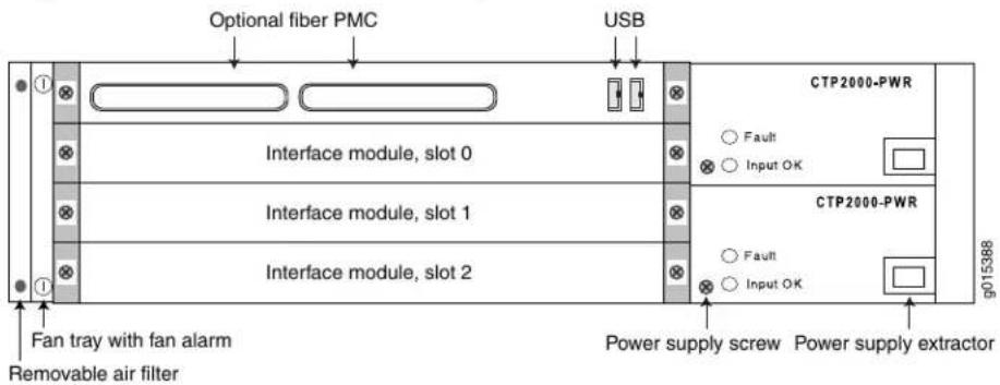
The front panel comprises the following components (see Figure 4 on page 5):
- Interface modules.
- Processor module—Two slots are available on this module for an optional fiber Gigabit Ethernet or Fast Ethernet PMC module. The primary SC connector is on the left side.
- Console port—This connector is not used by the CTP device.
- Power supply extractor—Push the button to eject the power supply module.
- Fan tray and air filter.
- PMC I/O—Both I/Os are supported.
- Clock module.
- Power supply—Use a standard IEC power cord for the AC version. Use a 22-AWG fork terminal connector for the DC version. Power redundancy is supported for the DC version.
There are no power switches on CTP2000 Series DC models, so a readily accessible disconnect device must be provided as part of the electrical installation of the unit. We recommend the 22-AWG wire for DC power terminals.
- Ethernet connection—Provides the 1-Gbps Ethernet connection to the IP network by means of a local Ethernet switch or router.
- USB connectors for console connection—Provides an asynchronous tty connection for locally configuring the CTP Series device. Connection to the console port through the USB connectors is possible only on the PP833 processor.

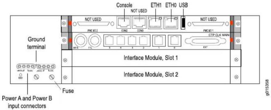
NOTE: The interface modules, clock module, power supply, Ethernet connection, and USB connectors for console connection are found on the rear panel in PP310 and PP332 processors.
Figure 5: CTP2024 Platform (AC Version, Rear View)

Figure 6: CTP2024 Platform (DC Version, Rear View)
Related Documentation
CTP2008 Platform on page 3.
- CTP2056 Platform on page 6
CTP2056 Platform
The Juniper Networks CTP2056 Circuit to Packet platform can have up to seven removable interface modules and one removable processor module, and is available in both AC-powered and DC-powered versions. It has a removable fan tray, and airflow is side-to-side. See Figure 7 on page 7, Figure 8 on page 8, and Figure 9 on page 8.
Figure 7: CTP2056 Chassis (AC and DC Version, Front View)

The front panel comprises the following components (see Figure 7 on page 7):
- Interface modules. - Processor module—Two slots are available on this module for an optional fiber Gigabit Ethernet or Fast Ethernet PMC module. The primary SC connector is on the left side.
- Console port—This connector is not used by the CTP device.
- Power supply extractor—Push the button to eject the power supply module.
• Fan tray and air filter.
- PMC I/O—Both I/Os are supported.
- Clock module.
- Power supply—Use a standard IEC power cord for the AC version. Use a 22-AWG fork terminal connector for the DC version. Power redundancy is supported for the DC version.
There are no power switches on CTP2000 Series DC models, so a readily accessible disconnect device must be provided as part of the electrical installation of the unit. We recommend the 22-AWG wire for DC power terminals.
- Ethernet connection—Provides the 1-Gbps Ethernet connection to the IP network by means of a local Ethernet switch or router.
- USB connectors for console connection—Provides an asynchronous tty connection for locally configuring the CTP Series device. Connection to the console port through the USB connectors is possible only on the PP833 processor.

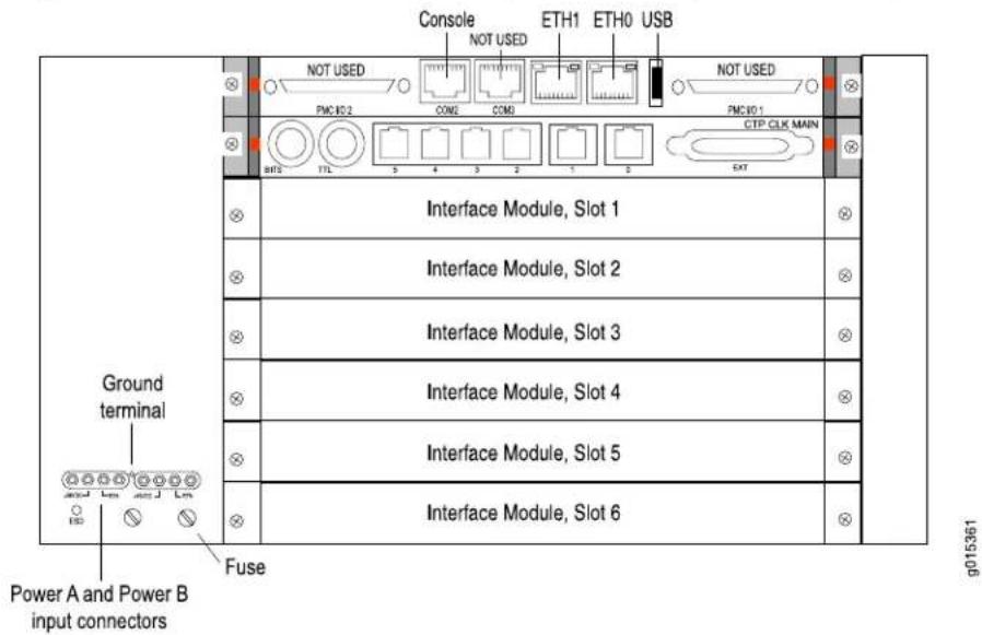
NOTE: The interface modules, clock module, power supply, Ethernet connection, and USB connectors for console connection are found on the rear panel in PP310 and PP332 processors.
Figure 8: CTP2056 Platform (AC Version, Rear View)

Figure 9: CTP2056 Platform (DC Version, Rear View)
Related Documentation
- CTP2008 Platform on page 3
- CTP2024 Platform on page 5
CHAPTER 2
CTP2000 Series Interface Modules
- CTP2000 Serial Interface Modules on page 9
- CTP2000 T1/E1 Interface Module on page 10
- CTP2000 Compression Interface Module on page 10
- CTP2000 Compression 2 High Density Interface Module on page 11
- CTP2000 4WE&M Interface Module on page 12
- CTP2000 2W-FXS and 2W-FXO Interface Modules on page 17
- CTP2000 8P-IRIG Interface Module on page 23
• CTP2000 Clock Interface Modules on page 23
CTP2000 Serial Interface Modules
The Juniper Networks CTP2008, CTP2024, and CTP2056 Circuit to Packet platforms have up to one, three, and seven serial interface modules, respectively. The interface modules are interchangeable between the platforms.
The following interface modules have two 100-pin connectors similar to the connectors provided on the CTP1004 and CTP1012 platforms. Each connector provides four ports by means of the quad cable. (See "Cabling the CTP2000 Platform Overview" on page 83.)
The lowest-numbered ports start at the top right.
- CTP2000 IM-8P—Provides the standard software-configurable data interfaces, including EIA530, EIA530A, RS-232, and V.35; 8 port.
- CTP2000 IM-8P-T1—Provides the standard software-configurable data interfaces, plus a configurable TI/E1 interface; 8 port.
- CTP2000 IM-8P-V—Provides the standard software-configurable data interfaces, plus a configurable 4WTO interface; 8 port.
Figure 10: Sample Serial Interface Module

g015362
Related Documentation
CTP2000 T1/E1 Interface Module on page 10.
- CTP2000 Compression Interface Module on page 10
- CTP2000 Compression 2 High Density Interface Module on page 11
- CTP2000 4WE&M Interface Module on page 12
- CTP2000 2W-FXS and 2W-FXO Interface Modules on page 17
- CTP2000 8P-IRIG Interface Module on page 23
CTP2000 T1/E1 Interface Module
The CTP2000 Series T1/Elinterface module has RJ-48 ports numbered 0–7 left to right. It provides a configurable eight-port E1 (2.048 MHz) or T1 (1.544 MHz) interface with AMI or B8ZS encoding. (See Figure 11 on page 10.)
Figure 11: CTP2000 IM-8P-T1/E1 Interface Module
Related Documentation

natural_image
Front view of a network device with multiple Ethernet ports and an I/O port (no text or symbols visible)CTP2000 Serial Interface Modules on page 9.
- CTP2000 Compression Interface Module on page 10
- CTP2000 Compression 2 High Density Interface Module on page 11
- CTP2000 4WE&M Interface Module on page 12
- CTP2000 2W-FXS and 2W-FXO Interface Modules on page 17
- CTP2000 8P-IRIG Interface Module on page 23
CTP2000 Compression Interface Module
The CTP2000 Series compression interface module enables serial data and voice bundles to be compressed and passed through a CTP2000 platform. (See Figure 12 on page 10.)
Voice bundles originating from the CTP2000 IM-8P-T1/E1, analog CTP2000 IM-4WE&M, IM-2WFXS, and IM-2WFXO modules use the CTP2000 compression module to compress the voice bundle. Voice bundles ranging from 1–24 channels on a T1 module, 1–30 channels on an E1 module, and 1–8 channels on a 4WE&M module can be bundled and connected through the compression module to compress the voice bundle and build the IP packet.
Figure 12: Compression Interface Module

The compression module supports these compression algorithms:
- MELP (2.4k)
G.729AB (8k)
• G.728 (16k)
• G.726 (16k)
G.726 (32k) - PMC (64k)
The module supports Mu-Law and A-Law companding, echo cancellation, silence suppression, fax/modem detection, and tone relay. You can configure the compression options when configuring the voice bundle.
Related Documentation
CTP2000 Compression 2 High Density Interface Module on page 11.
- CTP2000 T1/E1 Interface Module on page 10
- CTP2000 4WE&M Interface Module on page 12
- CTP2000 2W-FXS and 2W-FXO Interface Modules on page 17
- CTP2000 Compression 2 High Density Interface Module on page 11
CTP2000 Compression 2 High Density Interface Module
The CTP2000 Series Compression 2 High Density Interface Module enables serial data and voice bundles to be compressed and passed through a CTP2000 platform. It provides twice the digital signal processor (DSP) density of the original compression module.
Voice bundles originating from the CTP2000 IM-8P-T1/E1, analog CTP2000 IM-4WE&M, CTP2000-IM-2W-FXS, and CTP2000-IM-2W-FXO modules can use the CTP2000 Compression 2 High Density Interface Module to compress voice bundles. Voice bundles ranging from 1–24 channels on a T1 module, 1–30 channels on an E1 module, and 1–8 channels on a 4WE&M module can be bundled and connected through the Compression 2 High Density Module to compress the voice bundle and build the IP packet.
The Compression 2 High Density Compression Module supports these compression algorithms:
• G.711 (64k)
G.729AB (8k)
This module supports Mu-Law and A-Law companding, echo cancellation, silence suppression, fax/modem detection, and tone relay. You can configure the compression options when you configure the voice bundle.
Related Documentation
CTP2000 Compression Interface Module on page 10.
- CTP2000 T1/E1 Interface Module on page 10
- CTP2000 4WE&M Interface Module on page 12
- CTP2000 2W-FXS and 2W-FXO Interface Modules on page 17
CTP2000 4WE&M Interface Module
The CTP2000 Series 4WE&M interface module has eight 4-wire E&M ports and provides support for voice applications. It is used with voice compression (VCOMP) bundles in CTP2000 models and can be used only with a CTP2000 compression module.
Four-wire audio interfaces with E and M signaling interfaces (4WE&M) are commonly used as trunks between a central office (CO) and a private branch exchange (PBX). E and M is a type of supervisory line signaling that uses separate leads, called the "E" (ear) lead and "M" (mouth) lead and are traditionally used in the telecommunications industry. In 4WE&M signaling, two wires are used to receive and two wires are used to transmit, incorporating simplex control and differential payload in each channel. Type I, II, and V signaling is supported.
The 4WE&M interface module consists of a front card and a rear transition module (RTM). Port interfaces are located on connectors A and B of the RTM. (See Figure 13 on page 12 and Figure 14 on page 12.) The RJ-45 connectors are not used.
Figure 13: CTP2000 4WE&M Module

Figure 14: 4WE&M RTM


CAUTION: Power to the RTM is supplied from the interface module. Using an RTM other than those matched to the interface module may result in damage to both the interface module and the RTM. For example, never install a clock module RTM directly behind a 4WE&M interface module.
Voice ports can be used only by voice compression bundles (VCOMP) and cannot be used for CTP, SAToP, or CESoPSN bundles. There is no software configuration of 4WE&M ports. Signaling type is configured by means of jumpers (see Figure 16 on page 13 and
Table 3 on page 13). One or more 4WE&M ports can be mapped to a VCOMP bundle. The bundle configuration specifies the remote destination, the local port or ports transported by the bundle, voice compression options, as well as other configuration options.
Figure 15: Jumper Locations on the RTM

flowchart
graph TD
    A["A"] --> B["B"]
    B --> C["Unused dual RJ-45"]
    D["J5"] --> E["E&M type config jumpers"]
    F["J3"] --> E
    G["J17"] --> H["JP26"]
    I["JP26"] --> J["JP26"]
Figure 16: Jumper Positions for Signaling Types


NOTE: Jumper JP17 must be in Position 1-2 (see Table 3 on page 13) if any ports are set for Type II signaling. This jumper ties all signal battery (SB) signals to battery voltage (-48V).
Jumper JP26 is used to connect all signal grounds (SG) to the chassis ground. When jumper JP26 is in Position 1-2, the signal ground is connected to the chassis ground. In Position 2-3, it is isolated from the chassis ground.
Table 3: Jumper Positions for Configuring Port Signaling Type
| Signaling Type IJumper | Signaling Type II | Signaling Type V |
Position 1-2 Position 2-3 Position 1-2
Position 1-2 Position 2-3 Position 2-
Table 3: Jumper Positions for Configuring Port Signaling Type (continued)
| Signaling Type IJumper | Signaling Type II | Signaling Type V | ||
| Position 1-2Position 2-3Position 1-2 | ||||
| Position 1-2Position 2-3Position 2-3 | ||||
| Position 1-2Position 2-3Position 1-2 | ||||
| Position 1-2Position 2-3Position 2-3 | ||||
| Position 1-2Position 2-3Position 1-2 | ||||
| Position 1-2Position 2-3Position 2-3 | ||||
| Position 1-12Position 2-3Position 1-2 | ||||
| Position 1-2Position 2-3Position 2-3 | ||||
| Position 1-2Position 2-3Position 1-2 | ||||
| Position 1-2Position 2-3Position 2-3 | ||||
| Position 1-2Position 2-3Position 1-2, | ||||
| Position 1-2Position 2-3Position 2-3 | ||||
| Position 1-2Position 2-3Position 1-2 | ||||
| Position 1-2Position 2-3Position 2-3 |
The rear transition board uses two RJ-21 25-pair Telco connectors labeled A and B to interface the audio and control connections for eight E&M channels.

NOTE: Because of space limitations, a 180° RJ-21 connector is required. The CTP 4WE&M RTM supports clips to secure the RJ-21 cable connections to the RTM.
The R1/T1 pair and the R/T pair are the audio inputs and outputs of each port, respectively. For example, the audio input pair for port 0 is R1 and T1 on pins 2 and 27 of connector, The audio output pair for port 0 is R and T on pins 1 and 26.
See Table 4 on page 15 for signal definitions. See "CTP2000 4WE&M Interface Connector Pinouts" on page 41 for the connector A and B pinouts.
Table 4: Signal Definitions
| Signal DefinitionSignal Name | |
| Audio transmit pair, 600 OhmPort x T, R | |
| Audio receive pair, 600 OhmPort x T1, R1 | |
| E lead-outputPort x E | |
| M lead-inputPort x M | |
| Input for signal ground for signaling type IIPort x SG | |
| Port x SB | Output signal battery (-48V) for signaling type II. Note that JP17 must be in position 1-2. |
| GND | Signal ground. E and M leads are referenced to this ground for signaling types I and V. Use JP26 to connect this ground to chassis ground. |
Supervisory Signaling
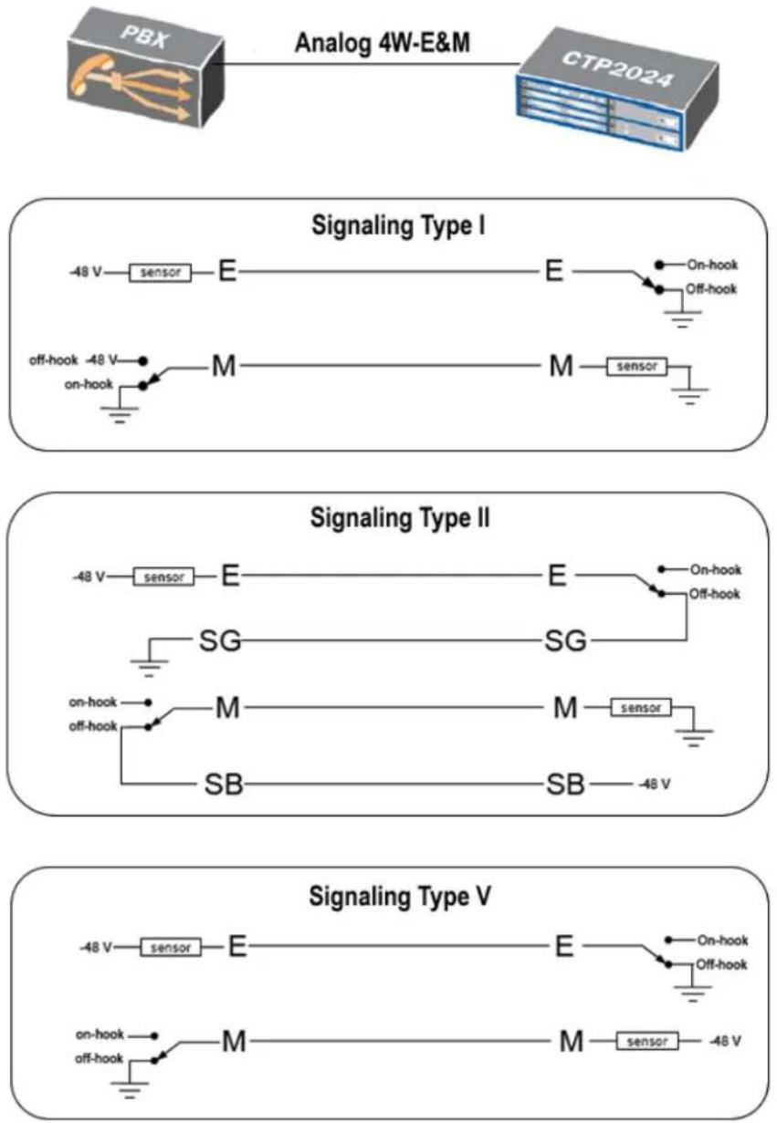
Supervisory signaling is the means by which a telephone user requests a service or initiates a call. The signaling unit (CTP platform) interacts with the trunk unit (PBX) by means of either two or four leads, depending on the signaling type. (See Figure 17 on page 16.) The signaling unit controls the E lead, whereas the trunk side controls the M lead. The two signaling states are on-hook and off-hook. During inactivity both units are on-hook. See Table 5 on page 17 for a summary of signaling types supported by the CTP2000 4WE&M module.
Figure 17: Analog 4WE&M Signaling Types
flowchart
graph TD
    subgraph Signaling Type I
        A["Analog 4W-E&M"] --> B["PBX"]
        B --> C["Sensor E"]
        C --> D["On-hook Off-hook"]
        E["Off-hook -48V on-hook"] --> F["M"]
        F --> G["Sensor M"]
        H["Signal Type I"] --> I["Sensor E"]
        J["Signal Type I"] --> K["Off-hook Off-hook"]
    end
    subgraph Signaling Type II
        L["Analog 4W-E&M"] --> M["Sensor E"]
        N["Analog 4W-E&M"] --> O["On-hook Off-hook"]
        P["On-hook off-hook"] --> Q["M"]
        R["On-hook off-hook"] --> S["SB"]
        T["Signal Type II"] --> U["Sensor E"]
        V["Signal Type II"] --> W["On-hook Off-hook"]
        X["Signal Type II"] --> Y["SG"]
        Z["Signal Type II"] --> AA["SG"]
        AB["Signal Type II"] --> AC["M"]
        AD["Signal Type II"] --> AE["M"]
        AF["Signal Type II"] --> AG["SB"]
        AH["Signal Type II"] --> AI["SB"]
        AJ["Signal Type II"] --> AK["-48V"]
    end
    subgraph Signaling Type V
        AL["Analog 4W-E&M"] --> AM["Sensor E"]
        AN["Analog 4W-E&M"] --> AO["On-hook Off-hook"]
        AP["On-hook off-hook"] --> AQ["M"]
        AR["On-hook off-hook"] --> AS["M"]
        AT["Signal Type V"] --> AU["Sensor E"]
        AV["Signal Type V"] --> AW["On-hook Off-hook"]
        AX["Signal Type V"] --> AY["Sensor M"]
        AZ["Signal Type V"] --> BA["sensor -48V"]
    end
Type I uses two leads—the E and M leads—for signaling. During inactivity, the E lead is open and the M-lead is connected to ground. The CTP device connects the E lead to a grounding point to signal off-hook, and the PBX connects the M lead to the battery (-48 V) to signal off-hook. Note that two signaling units cannot be connected back-to-back. With type I signaling, the signaling and trunk units must be connected by means of a common ground. Because the two sides are not isolated, they are susceptible to noise in the audio channels.
Type II uses four leads—E, SG, M, and SB—for signaling. During inactivity, both the E and M leads are open. To signal off-hook, the PBX connects the M lead to SB and the CTP device connects the E lead to SG. Note that two signaling units can be connected back-to-back if the appropriate signaling leads are swapped. With Type II signaling, the signaling unit and the trunk do not share a common ground.
Type V uses two leads, the E and M leads, for signaling. During inactivity, both the E and M leads are open. The CTP device signals off-hook by connecting the E lead to ground. The trunk circuit signals off-hook by connecting the M lead to ground. As with type I, with type V signaling, the two units share a common ground. Type V signaling allows for signaling units to be connected back-to-back.
Table 5: Supported Signaling Types for the CTP2000 4WE&M Module
| Signaling Type | Signaling Leads | CTP (E Lead)PBX (M Lead) | |
| Off-hookOn-hookOff-hookOn-I | |||
| GroundOpenBatteryGroundE, MI | |||
| SGOpenSBOpenE, M, SG, SBII | |||
| GroundOpenGroundOpenE, MV | |||
Related Documentation
CTR2000 Serial Interface Modules on page 9
- CTP2000 T1/E1 Interface Module on page 10
- CTP2000 Compression Interface Module on page 10
- CTP2000 Compression 2 High Density Interface Module on page 11
- CTP2000 2W-FXS and 2W-FXO Interface Modules on page 17
- CTP2000 8P-IRIG Interface Module on page 23
CTP2000 2W-FXS and 2W-FXO Interface Modules
The CTP2000 2W-FXS and CTP2000 2W-FXO interface modules provide analog support for voice applications. The 2W-FXS module has 24 two-wire FXS ports and the 2W-FXO interface module has 12 two-wire FXS ports. Both are paired with an RTM.
- FXS interfaces point to the subscriber and supply battery and ring voltage. Some FXS devices also provide dial tone, but CTP FXS interfaces do not. FXS interfaces detect when the attached FXO interface goes off-hook and on-hook. An FXS interface is a two-wire interface; the leads are called the tip (T) and the ring (R).
- FXO interfaces point to the central office. An analog phone is an example of an FXO device. The FXO interface must detect ring voltage (the analog phone rings) and provide on- and off-hook indication to the FXS interface. An FXO interface is a two-wire interface; the leads are called the tip (T) and the ring (R).
Both interface modules consist of a front module and an RTM. See Figure 18 on page 18 and Figure 19 on page 18 for the CTP2000 2W-FXS interface module.
Figure 18: Front Panel of CTP2000 2W-FXS Interface Module

Figure 19: Rear Panel of CTP2000 2W-FXS RTM

See Figure 20 on page 18 and Figure 21 on page 18 for the CTP2000 2W-FXO interface module.
Figure 20: Front Panel of CTP2000 2W-FXO Interface Module

Figure 21: Rear Panel of CTP2000 2W-FXO RTM

Both modules use connector A on the RTM. For both modules, connector B and the RJ-45 connectors are not used. See "CTP2000 FXS and FXO Interface Module Cables and Pinouts" on page 43 for connector pinout information.
You set the signaling by using the software on both modules. You cannot reconfigure the jumper parameters.
Required Cables and Pinouts
The CTP2000 2W-FXS and 2W-FXO interface modules require the use of double-shielded cables (copper braid plus aluminum mylar foil) to ensure EMI compliance. See "CTP2000 FXS and FXO Interface Module Cables and Pinouts" on page 43 for particulars about cable pinouts.
Analog FXS/FXO Loop-Start Signaling
There are two basic signaling protocols for FXS/FXO interfaces: loop-start and ground-start. Residential telephones use loop-start. Ground-start is typically used between a CO and a PBX to prevent "glare." Glare occurs when a call is established by the FXS device and the FXO device tries to make a call before the ring has been detected
When a call is initiated from the CO (or FXS) side, the FXS interface puts an AC ring voltage on the R lead (typically 70-90 Vrms). This ring voltage generates the ringing that you hear on an analog phone. When the FXO device answers the call (someone picks up the handset), the switch is closed between the T and R leads to complete a loop between the battery and ground in the FXS device. The FXS device detects the current, which flows from the battery (-48 V) through the R leads and back through the T leads to ground and stops the ring voltage.
When a call is initiated by the CPE (or FXO) device, the device goes off-hook, closing the connection between the T and R leads. The FXS device senses the current flow in the loop. Either the attached FXS device, or an upstream FXS device, provides dial tone to the FXO device after it is ready to accept the digits for the call destination. Providing dial tone is a form of start-dial supervision.
On the FXO device, when the device is on-hook, there is an open lead between the T and R leads. When the device is off-hook, the T and R leads are shorted with a typical load of \~300 Ohms. With loop-start, the T and R leads on the FXO interface can be switched without adversely affecting the signaling.
Glare occurs when a call is established by the FXS device and the FXO tries to make a call before the ring has been detected. Because it takes time for the FXO device (or person about to place a call) to detect ringing, it is possible for the FXS and FXO devices to bot seize the line without knowledge that the other end has done so. Ground-start circuits were established the minimize the possibility of glare. See “Analog FXS/FXO Ground-Start Signaling” on page 19.
Answer Supervision
Answer supervision is a signal used by the phone companies to determine when to start billing the originator of the call. Without answer supervision, you could get billed for the time the phone was ringing, even if the call was never picked up. When the FXS device has detected that the FXO device has gone off-hook, it reverses the polarity between the T and R leads for the duration of the call.
Disconnect Supervision
Disconnect supervision is a signal sent by the FXS device to the FXO device to indicate that the call has ended. The disconnect supervision signal can be either a battery reversal, battery denial (more than 350 ms), or a tone.
Note that loop-start circuits are not sensitive to tip/ring reversal. For example, the tip on the FXO device may be connected to either the tip or ring on the FXS.
Analog FXS/FXO Ground-Start Signaling
Ground-start signaling is used to minimize the potential for glare. Unlike loop-start circuits, ground-start circuits operate correctly only when the FXO tip is connected to the FXS tip and the FXO ring is connected to the FXS ring. Also, unlike loop-start circuits, the FXS and FXO grounds must be at the same potential.
When on-hook, the FXO ring is not connected to either the tip or ground. Likewise, when idle, the FXS tip is not connected to ground. When a call is initiated from the CO (FXS
side), the FXS grounds its tip and applies an AC ring voltage to the R lead. The FXO devi senses the grounded tip and AC ring voltage, and then goes off-hook by closing the loop (connecting R to T). The FXO has 100 ms to respond to the grounded tip/ring voltage. This time constraint is used to minimize glare. Once the FXO has closed the loop, the call proceeds as in the loop-start case.
When a call is initiated by the customer (FXO) side, the FXO starts by grounding the R lead. The FXS side responds by grounding its T lead. After the FXO has detected the grounded T lead, it closes the loop by removing the R lead from ground and closing the loop. With ground-start circuits, a far-end disconnect (FXS side) is indicated by the FXS disconnecting the tip from ground. The FXO senses the tip disconnect and goes on-hook by opening the loop.
Digital Signaling
Channel banks are often used to multiplex and demultiplex FXS or FXO interfaces onto T1 or E1 digital circuits. In the process, the analog signal is converted into pulse code modulation (PCM) and carried by one of the channels in the time-division multiplexing (TDM) circuit. For the interface to function properly, it must be able to signal the remote end of the T1/E1 connection as well as respond to signals from the remote end. Signaling is carried over the TDM circuit using either channel-associated signaling (CAS) or common-channel signaling (CCS). Generally, four signaling bits (A, B, C, and D) may be used; however, two signaling bits are most common (A and B).
For CTP analog voice products to work with digital devices, A and B bits are generated and transported across the network.
Digital FXS/FXO Loop-Start Signaling
For loop-start signaling of FXS and FXO interfaces, the A bit is used to indicate the state of the current loop, whereas the B bit is used for ringing. In the idle state (no ringing, FXO on-hook), A=0 and B=1. A=1 when the FXO is off-hook. Ringing is signaled by the B bit toggling between 0 and 1. Typically the toggling is 2 seconds off and 4 seconds on. For digital loop-state, the signaling is bidirectional.
Because hook indication is detected by the analog FXS interface, this device is responsible for generating the A bit. Likewise, because the analog FXS interface generates the ring voltage, this device must respond to the B bit. Because the signaling is bidirectional, the FXS side must echo the B bit when sending out the A bit.
The same logic applies to the FXO interface. The FXO device goes on/off-hook. It must respond to the A bit, going off-hook when A transitions from 0 to 1, and going on-hook when A goes from 1 to 0. The analog FXO interface detects ringing; therefore, it is responsible for generating the B bit value. The FXO device must echo the A value when sending out the digital signaling over the network.
Two situations for this call sequence must be considered: when the CTP is the FXO device and when the CTP platform is the FXS device. In both cases, before the call starts, the FXO is on-hook (A=1) and there is no ringing (B=1).
- For an analog CTP FXS interface, before the call starts, the CTP interface must generate A=0 and send both A=0 and B=1. When the call initiates from the CO, the B bit is
toggled. In response to this toggling, the CTP device generates a ring voltage on the analog FXS interface. When the attached FXO device goes off-hook, the CTP FXS interface detects the off-hook, sets the A bit to 1, and stops the ring voltage. During the call, the CTP device sends A = B = 1 signaling bits. At the end of the call, the FXO de goes back to on-hook, the CTP detects the on-hook, sends out A=0 and B=1 signaling bits, and the circuit returns to the idle state.
- For an analog CTP FXO interface, before the call starts the FXO is on-hook and no ringing is generated by the attached FXS device. In this, the idle state, the CTP interface generates B=1 and sends both A=0 and B=1. When the call comes in from the CO, the CTP FXO interface detects ring voltage and starts toggling the B bit. When the other end of the VCOMP bundle goes off-hook, it sends A=1 to the CTP. In response, the CTP FXO interface closes the loop, going off-hook. With ringing stopped, the CTP interface sends A = B = 1 during the call. At the end of the call the interface is again idle, and CTP interface sends A=0 and B=1 signaling bits.
Digital FXS/FXO Ground-Start Signaling
Unlike loop-start interfaces, in which the FXO and FXS each separately control a single signaling bit, with ground-start signaling each side controls both the A and B bits. We must consider each interface when the call is initiated by either interface. (See
Table 6 on page 21, Table 7 on page 21, Table 8 on page 22, and Table 9 on page 22). In all cases, when the FXO/FXS interface is idle, the FXO interface generates A = B = 1 signaling bits and the FXS A = 0, B = 1. When a call is in progress, either side initiates a call termination if it receives these signaling bits. For example, an FXS goes on-hook if it receives A=B=1 signaling bits.
Table 6: Ground-Start Signaling at FXO Interface for Call Initiated by FXO Interface
| Signaling Bits from FXOSI | |
| 11 (A=1, B=1)01 (A=0, B=1)Idle (before call st | |
| 1100FXO grounds ring | |
| tip) | 0100FXS goes off-hook (grounds |
| loop) | 0111FXO goes off-hook (closes |
| 0111Duration of call |
Table 7: Ground-Start Signaling at FXO Interface for Call Initiated by FXS Interface
| Signaling Bits from FXOSI | |
| 11 (A=1, B=1)01 (A=0, B=1)Idle (before call stSignaling Bits from FXOSi | |
| tip and sends AC ring signal) | 00/01 (B-bit toggles)01FXS goes off-hook (gr |
| loop) | 0111FXO goes off-hook (closes |
| 0111Duration of call |
Table 8: Ground-Start Signaling at FXS Interface for Call Initiated by FXS Interface
| Signaling Bits from FXSSi | |
| 01 (A=0, B=1)11 (A=1, B=1)Idle (before call st | |
| tip and sends AC ring signal) | 0100/01 (B-bit toggles)FXS goes off-hook (gr |
| loop) | 1101FXO goes off-hook (closes |
| 1101Duration of call |
Table 9: Ground-Start Signaling at FXS Interface for Call Initiated by FXO Interface
| Signaling Bits from FXSSig | |
| 01 (A=0, B=1)11 (A=1, B=1)Idle (before call st | |
| 0011FXO grounds ring | |
| tip and sends AC ring signal) | 0001FXS goes off-hook (grounds |
| loop) | 1101FXO goes off-hook (closes |
| 1101Duration of call |
Related Documentation
CTP2000 Serial Interface Modules on page 9.
- CTP2000 T1/E1 Interface Module on page 10
- CTP2000 Compression Interface Module on page 10
- CTP2000 Compression 2 High Density Interface Module on page 11
- CTP2000 4WE&M Interface Module on page 12
- CTP2000 8P-IRIG Interface Module on page 23
- CTP2000 FXS and FXO Interface Module Cables and Pinouts on page 43
CTP2000 8P-IRIG Interface Module
The CTP2000 8P-IRIG interface module enables an interrange instrumentation group time code (IRIG-B) signal to be transported through an IP network. IRIG-B is a special time code transmission format that uses a hybrid analog/digital physical interface. The IRIG-B standard consists of a family of rate-scaled serial time codes with formats containing up to three coded expressions or words. The IRIG-B pulse code contains one frame of 100 elements per second for the time of the year and GPS receiver status. IRIG-B encodes day of year, hour, minute, and second data on a 1-KHz carrier frequency, with an update rate of once per second.
The CTP2000 8P-IRIG module has eight ports. You can configure direction, high and low level output, and data range for this module. (See Figure 22 on page 23.)
Figure 22: CTP2000 8P-IRIG Interface Module

Related Documentation
CTP2000 Serial Interface Modules on page 9.
- CTP2000 T1/E1 Interface Module on page 10
- CTP2000 Compression Interface Module on page 10
- CTP2000 Compression 2 High Density Interface Module on page 11
- CTP2000 4WE&M Interface Module on page 12
- CTP2000 2W-FXS and 2W-FXO Interface Modules on page 17
CTP2000 Clock Interface Modules
Clock interface modules provide clock distribution between modules when the backplane is in use by voice applications.
The clock rear transition module (RTM) is used to input a reference clock into the CTP2000 platform. The clock RTM is installed in the rear of the chassis behind the first interface module as follows:
- On CTP2008 devices, the first slot above the processor RTM.
- On the CTP2024 and CTP2056 devices, the first slot below the processor RTM.
Clock distribution is accomplished through a "hub-and-spoke" configuration composed of a main module and a spoke module. Clock main modules (Figure 23 on page 24) and
clock spoke modules (Figure 24 on page 24) allow more clock input types in the CTP2000 chassis and provide the capability for clock distribution when both serial or T1/E1 interface modules and voice modules are installed in the same CTP2000 chassis.
Figure 23: Clock Main Module

Figure 24: Clock Spoke Module

The clock main module accepts an external clock reference and distributes it to the spoke module using a twisted pair cable. Each nonvoice card receives the clock on the first RJ-45 and sends it to the front module.
Figure 25: Hub-and-Spoke Setup

flowchart
graph TD
    A["Hub module"] --> B["CFP-CLK MAIN"]
    A --> C["CFP-CLK SPONE"]
    A --> D["CFP-CLK SPONE"]
    A --> E["CFP-CLK SPONE"]
    A --> F["CFP-CLK SPONE"]
    A --> G["CFP-CLK SPONE"]
    A --> H["CFP-CLK SPONE"]
    A --> I["CFP-CLK SPONE"]
    A --> J["CFP-CLK SPONE"]
    K["Spoke module"] --> L["CFP-CLK SPONE"]
    K --> M["CFP-CLK SPONE"]
    K --> N["CFP-CLK SPONE"]
    K --> O["CFP-CLK SPONE"]
    K --> P["CFP-CLK SPONE"]
    K --> Q["CFP-CLK SPONE"]
    K --> R["CFP-CLK SPONE"]
    K --> S["CFP-CLK SPONE"]
    K --> T["CFP-CLK SPONE"]
    K --> U["CFP-CLK SPONE"]
    K --> V["CFP-CLK SPONE"]
    K --> W["CFP-CLK SPONE"]
    K --> X["CFP-CLK SPONE"]
    K --> Y["CFP-CLK SPONE"]
    K --> Z["CFP-CLK SPONE"]
The main clock module has two BNC inputs (BITS and TTL), six RJ-45 ports, and one DB-25 port. Each RJ-45 port can be connected to one spoke module. The spoke module has one ingress RJ-45 port and one DB-25 interface. (See Figure 23 on page 24, Figure 24 on page 24, and Figure 25 on page 24.)

NOTE: BITS input is a T1/E1 line interface unit (LIU), with AMI (alternate mark inversion) encoding enabled and B8ZS/HDB3 (Zero Suppression) disabled. The equalization is set for a 0-133 feet cable. An internal 100 ohm termination is present, although it might need to be externally augmented based on the type of cabling used. Any valid AMI signal works properly and it is not restricted to only the "all 1" BITS signal but the ones density must be sufficient to prevent LOS (according to the ITU G.775 recommendation). The TTL input has a slice point of 3.3V/2 = 1.65V relative to chassis ground (GND). Therefore, any signal on the coaxial center conductor that transitions through that voltage registers a transition. There are many signals, besides TTL, that satisfy this criteria. An external termination must be provided that matches the impedance of the cable that goes to the BNC connector.
If you can configure the rate in CTP menu, then the TTL supports a frequency of 2048 KHz for the TTL clock input, provided the signal is good and noise-free (terminated properly). TTL is rate-agile, while BITS is restricted to T1/E1 frequencies.
The TTL input is high-impedance (no on-board termination provided) because a variety of cable types might exist that you can use to drive signal to this connector, such as RG-58 coax (50 ohm), RG-59 coax (75 ohm), or twisted pair (100-120 ohm). Instead of applying a particular impedance termination on the board and have it incorrectly done, we recommend that you configure the impedance termination based on your network environment. For example, a 50 ohm termination is needed if you are using RG-58/U coax cable, which has 50 ohm impedance.
External Reference Clock
The CTP2000 device can receive the external reference clock from any of the following inputs on the clock main module:
- The DB-25 connector. The clock input is provided on pins 24 and 11.
• The T1/E1 BITS inputs
• The T1/E1 TTL input
You configure the
:
The module provides
Installation Notes for Clock Interface Modules
-
Main modules and spoke modules are not hot-swappable.
• Nonvoice modules and voice modules can be installed in any slot. -
Main clock RTMs must be installed in slot 0 behind either a serial module or a T1/E1 module.
- Spoke RTMs must be installed behind serial modules and the lowest-numbered T1/E1 slot.
- If a T1/E1 module is installed in the slot that is closest to the processor, a spoke RTM is not needed behind any T1/E1 modules. They will synchronize to the H.100 clock.
- For platforms with only nonvoice boards (serial or T1/E1 module), only a main RTM is needed for external clock reference input.

NOTE: The clock RTM is installed in the rear of slot 0 next to the CPU slot. When you upgrade from an older processor to a PP833 processor, you can leave the CPU RTM in the chassis. Leaving the CPU RTM in the chassis will not adversely affect the functioning of the PP833 processor but will also not provide any functional value.
PART 2
Planning
• System Specifications on page 29
- Planning and Preparing the Site on page 35
• Equipment Rack Requirements on page 37
• Cable and Pinout Specifications on page 41
CHAPTER 3
System Specifications
- CTP2008 Platform Specifications and Certification on page 29
- CTP2024 Platform Specifications and Certification on page 31
- CTP2056 Platform Specifications and Certification on page 32
CTP2008 Platform Specifications and Certification
Table 10: CTP2008 Platform Specifications
| SpecificationCategory | |
| Weight | |
| 16 lb (7.25 kg)Chassis only | |
| Dimensions | |
| Chassis only | 1.75 in. (4.44 cm) high |
| 17.25 in. (43.81 cm) wide | |
| 11.25 in. (28.57 cm) deep | |
| Environmental Requirements | |
| 32° to 104° F (0° to 40° C)Ambient operating temperature | |
| 5% to 90% (noncondensing)Ambient operating humidity | |
| DC Input | |
| -40 to -72 VDCVoltage | |
| 3A @ -48 VDCCurrent | |
| 144 WPower | |
| 2 independent line feedsRedundancy (input power) | |
| AC Input | |
| Power required | 100–240 VAC50-60 HzAC line frequency |
| 2.0Nominal current (115V amps) | |
| 200 WPower | |
| Space Requirements | 3 ft. (90 cm) behind device or rack.Do not block air vents on the front or back of the device. |
| Airflow | Air intake occurs from the front of the device.Air is exhausted out the back of the device. |
| Safety Agency Certification | AS/NZS 60950:2000 Safety of Information Technology EquipmentCAN/CSA-C22.2, No. 60950-1-03, First Edition, Information Technology Equipment - Safety - Part 1: General RequirementsEN60825-1, Safety of Laser Products - Part 1: Equipment Class, Requirements, and User's Guide (2001)IEC 60950-1(2001-10) Ed. 1.0 Information Technology Equipment - Safety - Part 1: General RequirementsLow Voltage Directive (2006/95/EC)UL 60950-1, First Edition, Information Technology Equipment - Safety - Part 1: General Requirements |
| Electromagnetic Emissions Agency Certification | AS/NZS CISPR 22:2004EMC Directive (89/336/EEC)EN 300 132-2 (Narrowband and Wideband)EN55022 Class A (CISPR-22 Class A)EN55024, Annex C for WAN Equipment Performance Criteria A, B, and CEN 61000-4-2, EN 61000-4-3, EN 61000-4-4, EN 61000-4-6ETSI 300-386, Telecommunication Network Equipment; ElectroMagnetic Compatibility (EMC) requirementsIECS-03 Issue 3 Class AFCC Part 15 Class AVCCI (Voluntary Control Council for Interference by Information Technology Equipment) |
Related Documentation
CTP2024 Platform Specifications and Certification on page 31.
- CTP2056 Platform Specifications and Certification on page 32
CTP2024 Platform Specifications and Certification
Table 11: CTP2024 Platform Specifications
| SpecificationCategory | ||
| Weight | ||
| 20 lb (9.07 kg)Chassis only | ||
| Dimensions | ||
| Chassis only | 3.5 in. (8.89 cm) high17.25 in. (43.81 cm) wide11.25 in. (28.57 cm) deep | |
| Environmental Requirements | ||
| 32° to 104° F (0° to 40° C)Ambient operating temperature5% to 90% (noncondensing)Ambient operating humidity | ||
| DC Input | ||
| -40 to -72 VDCVoltage | ||
| 3A @ -48 VDCCurrent | ||
| 144 WPower | ||
| 2 independent line feedsRedundancy (Input power) | ||
| AC Input | ||
| 100-240 VACPower required | ||
| 50-60 HzAC line frequency | ||
| Nominal current (115V amps) | 2.0 | |
| Power | 200 W | |
| Space Requirements | 3 ft. (90 cm) behind device or rack.Do not block air vents on the front or back of the device. | |
| Airflow | Air intake occurs from the front of the device.Air is exhausted out the back of the device. | |
| Safety Agency Certification | AS/NZS 60950:2000 Safety of Information Technology EquipmentCAN/CSA-C22.2, No. 60950-1-03, First Edition, Information Technology Equipment - Safety - Part 1: General RequirementsEN60825-1, Safety of Laser Products - Part 1: Equipment Class, Requirements, and User's Guide (2001)EN 60950-1:2001, First Edition, Information Technology Equipment - Safety - Part 1: General RequirementsIEC 60950-1(2001-10) Ed. 1.0 Information Technology Equipment - Safety - Part 1: General RequirementsLow Voltage Directive (2006/95/EC)UL 60950-1, First Edition, Information Technology Equipment - Safety - Part 1: General Requirements | |
| Electromagnetic Emissions Agency Certification | AS/NZS CISPR 22:2004EMC Directive (89/336/EEC)EN 300 132-2 (Narrowband and Wideband)EN55022 Class A (CISPR-22 Class A)EN55024, Annex C for WAN Equipment Performance Criteria A, B, and CEN 61000-4-2, EN 61000-4-3, EN 61000-4-4, EN 61000-4-6ETSI 300-386, Telecommunication Network Equipment; ElectroMagnetic Compatibility (EMC) requirementsIECS-03 Issue 3 Class AFCC Part 15 Class AVCCI (Voluntary Control Council for Interference by Information Technology Equipment) | |
Related CTP2008 Platform Specifications and Certification on page 29. Documentation •CTP2056 Platform Specifications and Certification on page 32
CTP2056 Platform Specifications and Certification
Table 12: CTP2056 Platform Specifications
| SpecificationCategory | |
| Weight | |
| 27 lb (12.25 kg)Chassis only | |
| Dimensions | |
| Chassis only | 7.0 in. (17.8 cm) high |
| 17.25 in. (43.81 cm) wide | |
| 11.25 in. (28.57 cm) deep | |
| Environmental Requirements | |
| 32° to 104° F (0° to 40° C)Ambient operating temperature | |
| 5% to 90% (noncondensing)Ambient operating humidity | |
| DC Input | |
| -40 to -72 VDCVoltage | |
| 4A @ -48 VDCCurrent | |
| 192 WPower | |
| 2 independent line feedsRedundancy (input power) | |
| AC Input | |
| 100–240 VACPower required | |
| 50–60 HzAC line frequency | |
| 2.5Nominal current (115V amps) | |
| 250 WPower | |
| Space Requirements | 3 ft. (90 cm) behind device or rack.Do not block air vents on the front or back of the device. |
| Airflow | Air intake occurs from the front of the device.Air is exhausted out the back of the device. |
| Safety Agency Certification | AS/NZS 60950:2000 Safety of Information Technology EquipmentCAN/CSA-C22.2, No. 60950-1-03, First Edition, Information Technology Equipment - Safety - Part 1: General RequirementsEN60825-1, Safety of Laser Products - Part 1: Equipment Class, Requirements, and User's Guide (2001)EN 60950-1:2001, First Edition, Information Technology Equipment - Safety - Part 1: General RequirementsIEC 60950-1(2001-10) Ed.1.0 Information Technology Equipment - Safety - Part 1: General RequirementsLow Voltage Directive (2006/95/EC)UL 60950-1, First Edition, Information Technology Equipment - Safety - Part 1: General Requirements |
| Electromagnetic Emissions Agency Certification | AS/NZS CISPR 22:2004EMC Directive (89/336/EEC)EN 300 132-2 (Narrowband and Wideband)EN55022 Class A (CISPR-22 Class A)EN55024, Annex C for WAN Equipment Performance Criteria A, B, and CEN 61000-4-2, EN 61000-4-3, EN 61000-4-4, EN 61000-4-6ETSI 300-386, Telecommunication Network Equipment; ElectroMagnetic Compatibility (EMC) requirementsIECS-03 Issue 3 Class AFCC Part 15 Class AVCCI (Voluntary Control Council for Interference by Information Technology Equipment) |
| Related Documentation | CTP2008 Platform Specifications and Certification on page 29 |
| CTP2024 Platform Specifications and Certification on page 31 |
CHAPTER 4
Planning and Preparing the Site
- Before You Install a CTP Platform on page 35
• CTP2000 Environmental Requirements on page 35
Before You Install a CTP Platform
Before you install a Juniper Networks CTP Circuit to Packet platform:
- Verify that the electrical supply meets all power requirements. See the system specifications for the applicable CTP model.
- Verify that the site meets all environment specifications. Refer to the environmental requirements and the system specifications for the applicable CTP model.
- Verify that the cables you plan to use meet the specifications, and review the cabling recommendations.
- Verify the operation of all telephone circuits, digital services, and T1 facilities required for installation.
- Ensure that all IP requirements are met, such as IP addresses, subnet masks, and any specific routing protocol information.
CTP2000 Environmental Requirements
See one of the following topics for complete environmental specifications:
- CTP2008 Platform Specifications and Certification on page 29
- CTP2024 Platform Specifications and Certification on page 31
- CTP2056 Platform Specifications and Certification on page 32
Choose a location for the device that is dry, relatively dust free, well ventilated, and air conditioned. If you install equipment in a rack, be sure that the floor is capable of supporting the combined weight of the rack and the installed equipment. Place the device in a location with sufficient access to power and network cables.
Like other network devices, the device generates a significant amount of heat. You must provide a balanced environment so that the device performs properly and safely. See the individual system specifications for acceptable ranges of temperature and humidity.
Be sure to allow enough space around the device for adequate ventilation. Inadequate ventilation can cause the device to overheat.

CAUTION: Do not block the air vents on the device. Otherwise, the device might overheat.
Related Documentation
•Before You Install a CTP Platform on page 35
CHAPTER 5
Equipment Rack Requirements
• CTP2000 Rack Requirements on page 37
• CTP2000 Mechanical Requirements on page 37
• CTP2000 Space Requirements on page 38
• CTP2000 Rack Installation on page 38
• CTP Cabling Recommendations on page 38
CTP2000 Rack Requirements
When allocating equipment rack space, consider the following:
- Type of equipment racks recommended for the system
• Number of equipment racks required to hold your current system configuration - Future expansion
Make sure that your distribution rack meets basic mechanical and space requirements and complies with conventional standards. In the United States, use EIA-310-D Cabinets, Racks, Panels, and Associated Equipment, September 1992.
Related Documentation
CTP2000 Mechanical Requirements on page 37.
- CTP2000 Space Requirements on page 38
- CTP2000 Rack Installation on page 38
CTP2000 Mechanical Requirements
Follow these mechanical requirements for your rack:
- Select from the following rack options:
- Two-post rack—a freestanding enclosed cabinet with two mounting posts in the front
-
Telco-type rack—two adjacent mounting posts that you must secure to the floor or an overhead structure
-
Four-post rack—a freestanding open rack, either open or closed
- The rack must have at least two mounting posts.
- The distance between the mounting holes in the two posts must be 18.31 in. +/-.063 in., as specified in the EIA-310-D document.
- A fully loaded rack with three CTP2056 systems must structurally support at least 100 lb (46 kg).
- An optional mounting kit is available for midchassis mounting. Contact your Juniper Networks sales representative for more information.
| Related Documentation | CTP2000 Rack Requirements on page 37. |
| •CTP2000 Space Requirements on page 38 | |
| •CTP2000 Rack Installation on page 38 |
CTP2000 Space Requirements
If you use an enclosed rack for the device, ensure that there is a minimum of 3 in. of clearance between the inner side wall and the system. This clearance space ensures adequate air flow.
| Related Documentation | CTP2000 Rack Requirements on page 37. |
| CTP2000 Mechanical Requirements on page 37 | |
| CTP2000 Rack Installation on page 38 |
CTP2000 Rack Installation
To confirm proper equipment rack installation, verify the following:
- Racks are installed and electrically grounded according to manufacturer instructions.
- Equipment racks are anchored to the floor and, when possible, anchored to the ceiling as well.
• Equipment rack installations comply with applicable local, state, and national codes.
| Related Documentation | CTP2000 Mechanical Requirements on page 37. |
- CTP2000 Rack Requirements on page 37
- CTP2000 Space Requirements on page 38
•Special Guidelines for Installing CTP2056 Chassis in a Rack on page 68
CTP Cabling Recommendations
We suggest that you comply with the following recommendations:
- Ensure that cable distance and rate limits meet IEEE-recommended maximum speeds and distances for signaling purposes. For information about attenuation and power loss in optical fiber cables see:
- ANSI T1.646a-1997 Telecommunications - Broadband ISDN - Physical Layer Specification for User-Network Interfaces Including DS1/ATM (1997)
- ANSI T1.646-1995 Telecommunications – Broadband ISDN - Physical Layer Specification for User-Network Interfaces Including DS1/ATM (1995)
- Ensure that power cables deliver sufficient power to the device.
- Attach laser fiber connectors only to Class 1 laser devices in accordance with IEC 60825-1, Safety of Laser Products - Part 1.
- Route cables so that they do not restrict ventilation or airflow.
- Route cables so that modules and field-replaceable units are easily accessible.
- Route cables in a logical direction to prevent loss of connectivity to other equipment in the rack, associated equipment in adjacent racks, or to the backbone network.
- Consider using cable-management brackets to keep network cables untangled and orderly and to prevent cables from hindering access to other slots.
For additional cable recommendations, consult the document GR-63-CORE: Network Equipment Building System (NEBS) Requirements: Physical Protection, Issue 2, April 2002.
CHAPTER 6
Cable and Pinout Specifications
- CTP2000 4WE&M Interface Connector Pinouts on page 41
- CTP2000 FXS and FXO Interface Module Cables and Pinouts on page 43
- CTP2000 Series Console Cable Pinouts on page 46
• CTP Fast Ethernet and Power Cables on page 48
CTP2000 4WE&M Interface Connector Pinouts
- CTP2000 4WE&M RTM Connector A Pinouts on page 41
- CTP2000 4WE&M Connector B Pinouts on page 42
CTP2000 4WE&M RTM Connector A Pinouts
See Table 13 on page 41 for connector A pinout information. See "CTP2000 4WE&M Interface Module" on page 12 for signal definitions.
Table 13: CTP2000 4WE&M RTM Pinouts-Connector A
| Connector A | |||
| PinSignalSignalPin | |||
| 26Port 0 TPort 0 R1 | |||
| 2 | Port 0 R1 | 27Port 0 T1 | |
| 28Port 0 EPort 0 SG | |||
| 4 | Port 0 SB | 29Port 0 M | |
| 5 | Port 1 R | Port 1 T | 30 |
| 6 Port 1 T1Port 2 R1 | |||
| 7 | Port 2 SG | Port 1 E | 32 |
| 8 | Port 2 SB | Port 1 M | 3334Port 2 TPort 2 R9 |
| 35Port 2 T1Port 2 R110 | |||
| 36Port 2 EPort 2 SG11 | |||
| 37Port 2MPort 2 SB12 | |||
| 38Port 3 TPort 3 R13 | |||
| Port 3 R114 | 39Port 3 T1 | ||
| Port 3 EPort 3 SG05 | |||
| 16 | Port 3 SB | 41Port 3 M | |
| 25 | GND | GND | 50 |
CTP2000 4WE&M Connector B Pinouts
See Table 14 on page 42 for connector B pinout information. See "CTP2000 4WE&M Interface Module" on page 12 for signal definitions.
Table 14: CTP2000 4WE&M RTM Pinouts-Connector B
| Connector B | |||
| PIN | Signal | Signal | PIN |
| 1 | Port 4 R | Port 4 T | 26 |
| 2 | Port 4 R1 | Port 4 T1 | 27 |
| 3 | Port 4 SG | Port 4 E | 28 |
| 4 | Port 4 SB | Port 4 M | 29 |
| 5 | Port 5 R | Port 5 T | 30 |
| 6 | Port 5 R1 | Port 5 T1 | 31 |
| 7 | Port 5 SG | Port 5 E | 32 |
| 8 | Port 5 SB | Port 5 M | 33PINSignalSignalPIN |
| 34Port 6 TPort 6 R9 | |||
| 35Port 6 T1Port 6 R110 | |||
| 36Port 6 EPort 6 SG11 | |||
| 37Port 6MPort 6 SB12 | |||
| 38Port 7 TPort 7 R13 | |||
| 14 | Port 7 R1 | 39Port 7 T1 | |
| 15 | Port 7 SG | Port 7 E | 40 |
| 16 | Port 7 SB | Port 7 M | 41 |
| 25 | GND | GND | 50 |
Related Documentation
• CTP2000 4WE&M Interface Module on page 12
- CTP2000 FXS and FXO Interface Module Cables and Pinouts on page 43
• CTP2000 Series Console Cable Pinouts on page 46
CTP2000 FXS and FXO Interface Module Cables and Pinouts
• Required Cables on page 43
• RTM Pinout Locations on page 43
• FXS Connector Pinouts on page 44
• FXO Connector Pinouts on page 45
Required Cables
The CTP2000 2W-FXS and 2W-FXO interface modules require the use of double-shielded cables (copper braid plus aluminum mylar foil) to ensure EMI Compliance.
RTM Pinout Locations
Figure 26 on page 44 shows the pinout locations for both the CTP2000 2W-FXS and 2W-FXO interface modules.
Figure 26: RTM Pinouts for CTP2000 2W-FXS and 2W-FXO Interface Modules

FXS Connector Pinouts
The RTM for the CTP2000 2W-FXS interface module uses a RJ-21 25-pair Telco connector labeled A. The A connector has 24 FXS ports.
FXS R is connected to FXO T; FXS T is connected to FXO T.
Table 15 on page 44 lists the RTM pinouts for the FXS module.
Table 15: CTP2000 FXS Connector Pinouts on the RTM
| PinSignalSignalPin | |||
| 26Port 0 TPort 0 R1 | |||
| 27Port 1 TPort 1 R2 | |||
| 28Port 2 TPort 2 R3 | |||
| 29Port 3 TPort 3 R4 | |||
| 30Port 4 TPort 4 R5 | |||
| 31Port 5 TPort 5 R6 | |||
| Port 6 TPort 6 R7 | 32 | ||
| Port 7 R8 | Port 7 T | 33 | |
| Port 8 R9 | 34Port 8 T | ||
| 35Port 9 TPort 9 R10 | |||
| 36Port 10 TPort 10 R11 | |||
| 37Port 11 TPort 11 R12 | |||
| 38Port 12 TPort 12 R13 | |||
| 39Port 13 TPort 13 R14 | |||
| 40Port 14 TPort 14 R15 | |||
| Port 15 TPort 15 R16 41 | |||
| 17 | 42Port 16 TPort 16 R | ||
| 18 | Port 17 R | 43Port 17 T | |
| Port 18 TPort 18 R19 44 | |||
| 20 | Port 19 TPort 19 R | 45 | |
| 21 | Port 20 R | Port 20 T | 46 |
| Port 21 TPort 21 R22 47 | |||
| 23 | Port 22 R | Port 22 T | 48 |
| 24 | Port 23 R | Port 23 T | 49 |
FXO Connector Pinouts
The RTM for the CTP2000 2W-FXO interface module uses a RJ-2125-pair Telco connector labeled A. The A connector has 24 FXS ports.
FXO T is connected to FXS R; FXO T is connected to FXS T.
Table 16 on page 45 lists the RTM pinouts for the FXO module.
Table 16: CTP2000 FXO Connector Pinouts on the RTM
| PinSignalSignalPin | |||
| Port 0 T1 | 26Port 0 R | ||
| 3 | Port 1 T | 28Port 1 R | |
| 5 | Port 2 T | Port 2 R | 3032Port 3 RPort 3 T7 |
| 34Port 4 RPort 4 T9 | |||
| 36Port 5 RPort 5 T11 | |||
| 38Port 6 RPort 6 T13 | |||
| 40Port 7 RPort 7 T15 | |||
| 42Port 8 RPort 8 T17 | |||
| 44Port 9 RPort 9 T19 | |||
| 21 | Port 10 T | 46Port 10 R | |
| 48Port 11 RPort 11 T23 |
Related Documentation
CTP2000 2W-FXS and 2W-FXO Interface Modules on page 17
- CTP2000 4WE&M Interface Connector Pinouts on page 41
• CTP2000 Series Console Cable Pinouts on page 46
• CTP Fast Ethernet and Power Cables on page 48
CTP2000 Series Console Cable Pinouts
CTP2008, CTP2024, and CTP2056 devices with the new PP833 processor use a USB connector. The USB port on the device is connected to an RS-232 serial cable using a USB connector. The RS-232 cable is then connected to the console using an RJ-45 connector. CTP2000 series devices with the PP310 and PP332 processors use an RJ-45 connected to the COM2 port. This cable must be connected during the first boot process. Use a shielded cable for the COM2 port on the CTP2056 device. Figure 27 on page 47 displays the console cable pin configurations for CTP2000 series devices with the PP310 and PP332 processors. On the left is the RJ-45 connector, and on the right is the DB-9 connector with the pin numbering indicated.
The console connections are configured to the following parameters:
- Speed: 9600 bps
- Data bits: 8
- Stop bits: 1
- Flow control: Xon/Xoff
- Parity: none
Figure 27: CTP2000 Series Console Cable Pin Configurations for PP310 and PP332 Processors

Table 17 on page 47 and Table 18 on page 47 list console cable pinouts for CTP2000 Series devices based on the pin configurations.
Table 17: CTP2000 Series Console Cable Pinouts for PP310 and PP332 Processors
| Console DB-9 PinCTP RJ-45 Pin | |
| 8 CTS1 RTS | |
| 6 DSR2 DTR | |
| 5 GND3 GND | |
| 2 RXD4 TXD | |
| 3 TXD5 RXD | |
| 1 DCD6 (tied to pin 7) DCD | |
| 4 DTR7 DSR | |
| 7 RTS8 CTS |
Table 18: CTP2000 Series Console Cable Pinouts for the PP833 Processor
| Serial RS-232 CableCTP USB | |
| 8 VCCI GND Cable Detect | |
| 3 RXD2 RXD | |
| 2 TXD3 TXD | |
| 5 GND4 GND |
Related CTP Fast Ethernet and Power Cables on page 48. Documentation
CTP Fast Ethernet and Power Cables
- Fast Ethernet Cables on page 48
• DC Power Cables on page 48
Fast Ethernet Cables
The Ethernet connection is a standard RJ-45 connector. Typically, a straight-through cable is used to connect to a switch, and a crossover cable is used to connect to a route
DC Power Cables
For CTP chassis with DC power options, we recommend 18-AWG power cables.
PART 3
Safety
- General Safety Guidelines and Warnings on page 51
- Module Installation Safety Guidelines and Warnings on page 53
• Hardware Compliance on page 55
CHAPTER 7
General Safety Guidelines and Warnings
• CTP Safety Guidelines and Warnings on page 51
CTP Safety Guidelines and Warnings
For your safety, before installing the device, review all safety warnings in this section.

WARNING: The recommended maximum ambient temperature is 40^ C ( 104^ F). For safe operation take into consideration the internal temperature within the rack.

WARNING: Install equipment in the rack from the bottom upward. Doing this helps maintain the stability of the rack and reduces the chance of the rack tipping over.

WARNING: Do not insert any metal object, such as a screwdriver, into an open slot or the backplane. Doing so can cause electric shock and serious burns.

WARNING: For the larger CTP series devices, three people are required to install the device in a rack: two to lift the device into position and one to screw it to the rack.

WARNING: Connect the device or rack to ground (earth), and ensure that a reliable grounding path is maintained in the rack.

WARNING: Do not work on the device or connect or disconnect cables during lightning activity.

WARNING: Be sure that circuit breakers for the power source are in the OFF position before attaching power cables.

WARNING: Before servicing the device, turn off the power.

WARNING: Remove jewelry (including rings, necklaces, and watches) before working on equipment that is connected to power lines. Metal objects heat up when connected to power and ground and can cause serious burns or become welded to the terminals.

CAUTION: Evaluatetheoverall loading of the branch circuit beforeyou install any equipment into a rack.
Related Documentation
•Federal Communications Commission (FCC) Statement on page 56
•FCC Requirements for Consumer Products on page 57
•Food and Drug Administration, Center for Devices and Radiological Health on page 57
•Compliance with Canadian Regulations on page 58
•Before You Install a CTP Platform on page 35
CHAPTER 8
Module Installation Safety Guidelines and Warnings
- Safety Guidelines and Warnings for Installing CTP Modules on page 53
Safety Guidelines and Warnings for Installing CTP Modules
Before and during the installation process, observe the following warnings:

WARNING: Do not work on the device or connect or disconnect cables during lightning activity.

WARNING: Be sure circuit breakers for the power source are in the OFF position before attaching power cables.

WARNING: Remove jewelry (including rings, necklaces, and watches) before working on equipment that is connected to power lines. Metal objects heat up when connected to power and ground and can cause serious burns or become welded to the terminals.

WARNING: Do not insert any metal object, such as a screwdriver, into an open slot or the midplane. Doing so can cause electric shock and serious burns.

WARNING: Never attempt to repair parts of modules yourself. Only trained customer service personnel are authorized to service parts. Call Juniper Networks Customer Service to make arrangements to return defective modules for repair.
Related Documentation
•Required Tools and Safety Items for Installing CTP Modules on page 72
•Federal Communications Commission (FCC) Statement on page 56
•FCC Requirements for Consumer Products on page 57
•Food and Drug Administration, Center for Devices and Radiological Health on page 57
•Compliance with Canadian Regulations on page 58
CHAPTER 9
Hardware Compliance
- Declaration of Conformity for CTP2000 Platforms on page 55
• Federal Communications Commission (FCC) Statement on page 56
• FCC Requirements for Consumer Products on page 57 - Food and Drug Administration, Center for Devices and Radiological Health on page 57
• Compliance with Canadian Regulations on page 58
Declaration of Conformity for CTP2000 Platforms
Figure 28 on page 56 shows the Declaration of Conformity for the CTP2000 platforms.
Figure 28: CTP2000 Declaration of Conformity

Declaration of Conformity
Juniper Networks, Inc. 10 Technology Park Drive Westford, MA 01886 USA
declares that under our sole responsibility the product(s)
Circuit-to-Packet Network Device Model CTP2000 Series
are in conformity with the provisions of the following EC Directives, including all amendments, and with national legislation implementing these directives:
Low Voltage Directive 73/23/EEC EMC Directive 89/336/EEC
and that the following harmonized standards have been applied
EN 60950-1:2001+A11 EN 60825-1:1994+A1+A2
EN 300 386 V1.3.3:2005 EN 55024:1998 + A1 + A2 EN 55022:1998 + A1(2000) + A2(2003) Class A

Place Westford, MA, USA
Signature Susanne Delisle
Date 06/20/2007
Related Documentation
CTP2008 Platform Specifications and Certification on page 29.
- CTP2024 Platform Specifications and Certification on page 31
- CTP2056 Platform Specifications and Certification on page 32
Federal Communications Commission (FCC) Statement
This equipment has been tested and found to comply with the limits for a Class A digital device, pursuant to Part 15 of the FCC Rules. These limits are designed to provide reasonable protection against harmful interference when the equipment is operated in a commercial environment. This equipment generates, uses, and can radiate radio frequency energy and, if not installed and used in accordance with the instruction manual,
may cause harmful interference to radio communications. Operation of this equipment in a residential area is likely to cause harmful interference in which case the user will be required to correct the interference at their own expense.
This equipment is designed for use with properly shielded and terminated cables. Refer to the installation sections of this manual before operation.
Reference: CFR 47, Part 15J, Sect 15.105 April 18, 1989
Caution: Changes or modifications to this equipment not expressly approved by the party responsible for compliance could void the user's authority to operate the equipment.
Related Documentation
FCC Requirements for Consumer Products on page 57.
•Food and Drug Administration, Center for Devices and Radiological Health on page 57
•Compliance with Canadian Regulations on page 58
FCC Requirements for Consumer Products
This equipment complies with FCC rules, Part 68. On the back side of this equipment is a label that contains, among other information, the FCC Registration Number and Ringer Equivalence Number (REN) for this equipment. If requested, provide this information to your telephone company.
If this equipment causes harm to the telephone network, the telephone company may discontinue your service temporarily. If possible, they will notify you in advance. But if advance notice is not practical, you will be notified as soon as possible. You will be advised of your right to file a complaint with the FCC.
Your telephone company may make changes in its facilities, equipment, operations, or procedures that could affect the proper operation of your equipment. If they do, you will be given advance notice to give you an opportunity to maintain uninterrupted service.
If you experience trouble with this equipment, please contact the manufacturer for warranty/repair information. The telephone company may ask that you disconnect this equipment from the network until the problem has been corrected or until you are sure that the equipment is not malfunctioning.
Related Documentation
Federal Communications Commission (FCC) Statement on page 56.
•Food and Drug Administration, Center for Devices and Radiological Health on page 57
•Compliance with Canadian Regulations on page 58
Food and Drug Administration, Center for Devices and Radiological Health
This equipment complies with 21 CFR 1040.10 and 1040.11 for the safe use of lasers.
Related Documentation
Federal Communications Commission (FCC) Statement on page 56.
•FCC Requirements for Consumer Products on page 57
•Compliance with Canadian Regulations on page 58
Compliance with Canadian Regulations
• Industry Canada Notice on page 58
• Canadian Department of Communications Explanatory Notes on page 59
Industry Canada Notice
• Industry Canada Notice CS-03 on page 58
• Avis CS-03 d'Industrie Canada on page 58
Industry Canada Notice CS-03
The Industry Canada label identifies certified equipment. This certification means that the equipment meets certain telecommunications network protective, operation and safety requirements as prescribed in the appropriate Terminal Equipment Technical Requirements document(s). The Department does not guarantee that the equipment will operate to the user's satisfaction. Before installing this equipment, users should ensure that it is permissible to be connected to the facilities of the local telecommunications company. The equipment must also be installed using an acceptable method of connection. The customer should be aware that compliance with the above conditions may not prevent degradation of service in some situations.
Repairs to certified equipment should be coordinated by a representative designated by the supplier. Any repairs or alterations made by the user to this equipment, or equipment malfunctions, may give the telecommunications company cause to request the user to disconnect the equipment.
Users should ensure for their own protection that the electrical ground connections of the power utility, telephone lines and internal metallic water pipe system, if present, are connected together. This precaution may be particularly important in rural areas.
Caution: Users should not attempt to make such connections themselves, but should contact the appropriate electric inspection authority, or electrician, as appropriate.
Notice: The Ringer Equivalence Number (REN) assigned to each terminal device provides an indication of the maximum number of terminals allowed to be connected to a telephone interface. The termination on an interface may consist of any combination of devices subject only to the requirement that the sum of the Ringer Equivalence Numbers of all the devices does not exceed 5.
Canadian Department of Communications Explanatory Notes
• DOC Explanatory Notes: Equipment Attachment Limitations on page 59
- Notes explicatives du ministère des Communications: limites visant les accessoires on page 60
DOC Explanatory Notes: Equipment Attachment Limitations
The Canadian Department of Communications label identifies certified equipment. This certification meets certain telecommunication network protective, operational and safety requirements. The department does not guarantee that the equipment will operate to the users satisfaction.
Before installing the equipment, users should ensure that it is permissible to be connected to the facilities of the local telecommunications company. The equipment must also be installed using an acceptable method of connection. In some cases, the company's inside wiring associated with a single line individual service may be extended by means of a certified connector assembly (telephone extension cord). The customer should be aware that compliance with the above condition may not prevent degradation of service in some situations.
Repairs to certified equipment should be made by an authorized Canadian maintenance facility designated by the supplier. Any repairs or alterations made by the user to this equipment, or equipment malfunctions, may give the telecommunications company cause to request the user to disconnect the equipment.
Users should ensure for their own protection that the electrical ground connections of the power utility, telephone lines and internal metallic water pipe system, if present, are connected together. This precaution may be particularly important in rural areas.
Caution: Users should not attempt to make such connections themselves, but should contact the appropriate electrical inspection authority, or electrician, as appropriate.
Related Documentation
•Federal Communications Commission (FCC) Statement on page 56
• FCC Requirements for Consumer Products on page 57
•Food and Drug Administration, Center for Devices and Radiological Health on page 57
PART 4
Installation
- Unpacking and Inspecting the CTP Platform on page 63
• Installing the Chassis on page 67
• Installing Modules on page 71
• Installing and Removing SFPs in a CTP Module on page 77 - Upgrading Components for Memory Upgrades on page 81
• Cabling on page 83
• Powering On on page 89 - Accessing the CTP2000 Platform on page 93
CHAPTER 10
Unpacking and Inspecting the CTP Platform
- Before You Unpack the CTP Platform on page 63
- Unpacking the CTP Device on page 63
- Inspecting Platform Components and Accessories on page 64
• If You Detect or Suspect Damage on page 64 - Contacting Juniper Networks on page 65
Before You Unpack the CTP Platform
Before you begin unpacking the device, be sure you have the following tools:
• No. 2 Phillips screwdriver
- Utility knife
- Mechanical lift, or at least two people to assist in lifting
Related Documentation
Unpacking the CTP Device on page 63.
• Inspecting Platform Components and Accessories on page 64
• If You Detect or Suspect Damage on page 64
•Contacting Juniper Networks on page 65
Unpacking the CTP Device
Depending on the device, it may be delivered boxed, bolted, and strapped to a skid. For your convenience, we recommend that you unpack the device in the location where you want to install it.

WARNING: For the larger CTP series devices, three people are required to install the device in a rack: two to lift the device into position and one to screw it to the rack.
To unpack the device:
- Cut the two straps that secure the carton to the skid, open the carton from the top, and remove the box of accessories that sits on top of the device.
- Unlock the four plastic clips that hold the box to the skid by squeezing them in their center and pulling out, and then lift the carton off the device.
- Remove the three screws that attach each of the two L-brackets to the device.
- To avoid scratching the device when removing it from the skid, detach one of the L-brackets from the skid by removing the three screws.
Related Documentation
Before You Unpack the CTP Platform on page 63.
• Inspecting Platform Components and Accessories on page 64
• If You Detect or Suspect Damage on page 64
- Contacting Juniper Networks on page 65
Inspecting Platform Components and Accessories
After you remove the equipment from the shipping containers:
- Confirm the contents of each container.
- Inspect all external surfaces and external connectors for visible signs of damage.
- Inspect all accessories shipped with each unit.
- Document any damage noted during your inspection.
- Confirm that the platform has the correct number and type of modules for your ordered configuration.
Related Documentation
Before You Unpack the CTP Platform on page 63.
• Unpacking the CTP Device on page 63
• If You Detect or Suspect Damage on page 64
•Contacting Juniper Networks on page 65
If You Detect or Suspect Damage
If you detect or suspect damage to any equipment:
- Contact the shipper responsible for delivery, and formally report the damage.
- Contact your Juniper Networks sales representative or reseller.
Related Documentation
Before You Unpack the CTP Platform on page 63.
• Unpacking the CTP Device on page 63
• Inspecting Platform Components and Accessories on page 64
- Contacting Juniper Networks on page 65
Contacting Juniper Networks
Please contact Juniper Networks at 1-888-314-JTAC (from the United States, Canada, or Mexico) or 1-408-745-9500 (from elsewhere), or contact your sales representative if you have any questions or concerns. See "Contacting Customer Support" on page 115 for complete contact information.
Related Documentation
•Before You Unpack the CTP Platform on page 63
• Unpacking the CTP Device on page 63
• Inspecting Platform Components and Accessories on page 64
• If You Detect or Suspect Damage on page 64
CHAPTER 11
Installing the Chassis
- Before You Install the CTP2000 Platform on page 67
• Installing the CTP2000 Platform in Freestanding Mode on page 67 - Special Guidelines for Installing CTP2056 Chassis in a Rack on page 68
• Installing the CTP2000 Platform in a Rack on page 68
Before You Install the CTP2000 Platform
Before installing the platform:
• Refer to the platform specifications for the particular CTP model or series.
- Have a plan for installing the device that takes into consideration future expansion.
- Have the tools and accessories needed to complete the installation.
- Read and understand the clearance requirements for the front and back of the chassis for cable routing and other unit access. See "CTP2000 Environmental Requirements" on page 35 for more information.
- Read and understand the clearance requirements for the top and bottom of the chassis to ensure adequate ventilation.
- Prepare the equipment racks by measuring and marking space for each device and plenum you plan to install.
Related Documentation
Installing the CTP2000 Platform in Freestanding Mode on page 67.
•Installing the CTP2000 Platform in a Rack on page 68
Installing the CTP2000 Platform in Freestanding Mode
When installing the device on a table top or in any other freestanding mode, be sure to leave enough space around the device for adequate ventilation. Position the chassis with easy access to the connections that it needs for power, local communications, and remote communications.

WARNING: At least two people are required to lift the device. Three people are required for the heavier CTP platforms.

CAUTION: To prevent electrostatic damage to the device and its components, make sure that persons handling the device wear an antistatic device.
Related Documentation
Before You Install the CTP2000 Platform on page 67.
•Installing the CTP2000 Platform in a Rack on page 68
•Cabling the CTP2000 Platform Overview on page 83
Special Guidelines for Installing CTP2056 Chassis in a Rack
Before installing the CTP2056 platform in a rack, consider the following guidelines:
- You can install up to four CTP2056 chassis in a single 7-ft. (2.1-m) rack. Installing multiple devices in a single rack enables you to maximize your available space.
- Install the CTP2056 chassis on the bottom of the rack. Mount lighter devices higher in the rack.
Related Documentation
CTP2000 Rack Requirements on page 37.
•Installing the CTP2000 Platform in a Rack on page 68
Installing the CTP2000 Platform in a Rack
To install the CTP platform in a rack, you need:
• Phillips screwdriver
- Four 10-32 x 3/8 Phillips screws for each device to be installed
Follow these guidelines:
- Following your installation plan, use a tape measure and marking pen to measure and mark space on each equipment rack for each platform component. For horizontal spacing, follow Network Equipment Building System (NEBS) requirements.
- With one person standing on the left side of the device and another standing on the right side, lift the device into the rack.
-
Position the device in its designated location in the equipment rack. Make sure the holes of the mounting brackets align evenly with the holes of the equipment rack on both sides.
-
Starting at the bottom of the device, secure the device in the equipment rack by using the 10-32 x 3/8 Phillips screws. Have a third person do this for the larger and heavier CTP chassis.
- Connect the necessary cables. (See "Cabling the CTP2000 Platform Overview" on page 83 for instructions about installing the cables.)
Related Documentation
•Before You Install the CTP2000 Platform on page 67
•Installing the CTP2000 Platform in Freestanding Mode on page 67
•Cabling the CTP2000 Platform Overview on page 83
CHAPTER 12
Installing Modules
- CTP2000 Modules Installation Overview on page 71
- Protecting CTP2000 Modules and Slots on page 71
- Required Tools and Safety Items for Installing CTP Modules on page 72
- Installing a CTP Interface Module, Processor Module, or Clock Module on page 73
- Removing a CTP Interface Module, Processor Module, or Clock Module on page 73
• Installing or Removing a CTP2000 Series CompactFlash Card on page 74
• Installing a PMC on CTP2000 Platforms on page 75
CTP2000 Modules Installation Overview
In CTP2000 platforms, you can install interface modules in the front and rear of the device.
Related Documentation
Protecting CTP2000 Modules and Slots on page 71.
•Required Tools and Safety Items for Installing CTP Modules on page 72
•Safety Guidelines and Warnings for Installing CTP Modules on page 53
•Installing a CTP Interface Module, Processor Module, or Clock Module on page 73
•Installing or Removing a CTP2000 Series CompactFlash Card on page 74
•Installing a PMC on CTP2000 Platforms on page 75
•Installing SFPs in a CTP2000 Module on page 77
Protecting CTP2000 Modules and Slots
To prevent damage from electrostatic discharge, wear an antistatic wrist strap, and connect it to one of the jacks when handling components. The CTP2056 has an ESD (electrostatic discharge) grounding jack located in the rear lower-left corner of the chassis near the power switch. There are no ESD jacks on the other CTP2000 platforms, so you must use another grounding device.
To protect the modules, components, and slots when installing components, observe the following guidelines:

CAUTION: When handling components, use an antistatic wrist strap connected to one of the device's ESD grounding jacks or to another grounding device. This action helps to protect the module from damage by electrostatic discharge.

CAUTION: Always handle a module by its edges. Do not touch the components, pins, leads, or solder connections.

CAUTION: If you meet strong resistance when attempting to seat a module using the ejectors, remove it from the chassis and confirm that the slot is designed to hold the module. Also, be sure that you have aligned the left and right edges in the correct matching module guides.

CAUTION: Be sure to cover every empty slot with a blank filler panel to protect the device from dust or other foreign substances and to ensure proper device cooling.

CAUTION: Do not discard the antistatic bag. When a module is not in use, store it in an antistatic bag.
Related Documentation
Safety Guidelines and Warnings for Installing CTP Modules on page 53. •Required Tools and Safety Items for Installing CTP Modules on page 72
Required Tools and Safety Items for Installing CTP Modules
You need the following tools to install a CTP module:
- Phillips screwdriver
- Flathead screwdriver
- ESD wrist strap or other grounding device
Related Documentation
Safety Guidelines and Warnings for Installing CTP Modules on page 53.
•Installing a CTP Interface Module, Processor Module, or Clock Module on page 73
Installing a CTP Interface Module, Processor Module, or Clock Module
To install a CTP module:
- Ground yourself by using an antistatic wrist strap or other device, and connect it to one of the ESD grounding jacks, if available, or another grounding device.
- Choose the slot where you want to insert the module.
- With a Phillips screwdriver, loosen the screws that secure the blank filler panel covering the empty chassis slot, if present, and remove the filler panel.
- Remove the module from its antistatic bag, being careful not to touch module components, pins, leads, or solder connections.
- Verify that the ejectors are in the open position (facing outward).
- Guide the module into the chassis by placing it between the guides of the selected slot and pushing the module until it stops.
The module stops sliding when the ejectors make contact with the chassis.

CAUTION: If you meet strong resistance when attempting to seat the module using the ejectors, remove it from the chassis, and confirm that the slot is designed to hold the component. Also, be sure that you have aligned the left and right edges in the correct matching tracks.
-
Insert the module into the midplane by simultaneously pressing both ejectors inward and exerting forward pressure on the module. The small red release buttons should click into place.
-
Tighten the module's captive screws using a Phillips screwdriver.

NOTE: Tighten the captive screws completely before installing an adjacent module so that proper electromagnetic interference (EMI) gasket compression occurs. Failure to do this can make it difficult to install adjacent modules.
- Go to Cabling a CTP Interface Module.
Related Documentation
Removing a CTP Interface Module, Processor Module, or Clock Module on page 73.
Removing a CTP Interface Module, Processor Module, or Clock Module

NOTE: We recommend that you issue the slot disable command from the CLI before removing a line module.

CAUTION: If you do not use the halt command before powering down the CTP device, the CompactFlash card might become corrupted.
To remove a CTP module:
- Issue the halt command.
- Ground yourself by using an antistatic wrist strap or other device, and connect it to an ESD grounding jack, if available, or another grounding device.
- Use a Philips screwdriver to loosen the captive screws located at the top and bottom of the module panel.
- If the module has ejector handles, press the red release buttons, and pull the ejector handles outward to the open position.
- Carefully slide the module out of the chassis.
- Place the module in its antistatic bag, being careful not to touch module components, pins, leads or solder connections.
- Cover the empty chassis slot with a blank filler panel, and tighten the filler panel's captive screws using a Phillips screwdriver. Turn both screws several times before tightening them completely.
Related Documentation
Installing a CTP Interface Module, Processor Module, or Clock Module on page 73.
Installing or Removing a CTP2000 Series CompactFlash Card
To remove or install the CompactFlash card for the CTP2000serieswith the new PP833 processor:
- Power off the unit.
- Remove the PP833 PRC card by unscrewing the retainingscrews and pushing the extractors outward with the latching buttonsdepressed.
- You can then remove or install the CompactFlash card in the flash socket.
- Reinstall the PP833 PRC card into the chassis, and secure the retaining screws.
To remove or install the CompactFlash card for the CTP2000 series with the PP310 and PP332 processors:
- Power off the unit.
- Remove the processor RTM by unscrewing the retaining screws and pushing the extractors outward with the latching buttons depressed.
-
Remove the CompactFlash card retaining screw and nut. You can then remove or install the CompactFlash card in the flash socket (see Figure 29 on page 75).
-
Reinstall the CompactFlash card retaining screw and nut.
- Reinstall the processor RTM into the chassis, and secure the retaining screws.
Figure 29: CompactFlash on the RTM
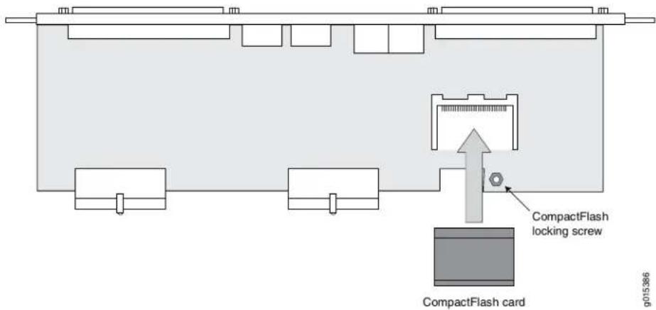
Related Documentation
Installing a CTP Interface Module, Processor Module, or Clock Module on page 73.
Installing a PMC on CTP2000 Platforms
The PCI mezzanine card (PMC) is mounted on the processor module and can be installed or replaced in the field. Figure 30 on page 75 displays the location of the PMC.
Figure 30: CTP2000 Platforms PMC Location
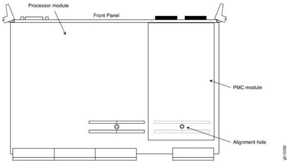
To install a PMC:
- Confirm that the device is powered off.
- Remove the RTM on PP310 and PP332 processors by unscrewing the retaining screws and pushing the extractors outward while depressing the latching buttons.
- If a PMC was not previously installed, a shield may have been inserted in the PMC slot of the processor's front panel. Remove this shield by gently pushing it out from behind the panel.
- The PMC has four screws. Two of the screws are secured to standoffs, and two are attached to the front assembly of the PMC. Remove the two screws secured to the standoff, leaving the standoff attached to the PMC. Remove the two screws on the front assembly located on the side with the standoffs. The front assembly should remain attached to the PMC hardware. Keep the screws for reattachment.
- Align the PMC with the printed circuit board connectors toward the processor board and with the fiber connectors inserted through the processor's front panel. Align the alignment post on the processor module with the PMC's alignment hole.
- Gently press the PMC into the processor module.
- From the back of the processor module, use the four Phillips head screws to secure the two PMC standoff posts and PMC front assembly to the processor module.
- Reinstall the processor RTM in the reverse procedure of removing it. Be sure that the screws and latching are secure
Related Documentation
•Installing a CTP Interface Module, Processor Module, or Clock Module on page 73
CHAPTER 13
Installing and Removing SFPs in a CTI Module
• Installing SFPs in a CTP2000 Module on page 77
- Removing SFPs in a CTP2000 Module on page 78
Installing SFPs in a CTP2000 Module
This section describes how to install small form-factor pluggable transceivers (SFPs) on interface modules that support these devices. In the current release, the CTP-FX2000GE-UPG supports SFPs.
You can replace the SFPs without disabling the interfaces or removing the module from the device.
To install SFPs:
- Ground yourself by using an antistatic wrist strap or other device, and connect it to an ESD grounding jack.
- Identify the following items on the SFP (Figure 31 on page 78):
• The connection circuitry on the base
- The cable connectors on the front (which are protected by a dust cover)
Figure 31: Representative SFP


CAUTION: Be sure to position the SFP correctly before you install it.
-
Hold the SFP so that:
-
The connection circuitry is adjacent to the module's faceplate.
-
The cable connectors are visible when you install the SFP.
-
Slide the SFP as far as you can into the module until the SFP clicks into place. If the SFP does not slide smoothly into the module, make sure that the orientation of the SFP is correct.
- Gently pull the SFP to confirm that it is inserted correctly. If the SFP comes out of the slot when you pull it, repeat Step 4.
- Remove the dust cover that protects the cable connectors.
- Connect the new cables to the SFP.
Related Documentation
Removing SFPs in a CTP2000 Module on page 78.
Removing SFPs in a CTP2000 Module
This section describes how to replace small form-factor pluggable transceivers (SFPs) on interface modules that support these devices. You can replace the SFPs without disabling the interfaces or removing the module from the device.
To remove an SFP:
- Obtain an antistatic container for the SFP you plan to remove.
-
Ground yourself by using an antistatic wrist strap or other device, and connect it to an ESD grounding jack.
-
Disconnect the cable from the SFP on the module.
-
Identify the release mechanism for the SFP.
Different SFPs use different release mechanisms. See Figure 32 on page 79 for possible release mechanisms, which include:
• A button that you press inward
• A ring that you press inward
• A bar that you pull sideways, then outward
• A tab that you pull sideways, then outward
Figure 32: Possible Release Mechanisms on the SFP
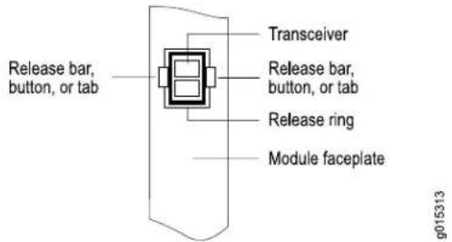
- Release the SFP and pull it out of the slot.
- Place the SFP into an antistatic bag.
Related • Installing SFPs in a CTP2000 Module on page 77 Documentation
CHAPTER 14
Upgrading Components for Memory Upgrades
- Upgrading CTP2000 Series Components for Memory Upgrades on page 81
Upgrading CTP2000 Series Components for Memory Upgrades
Certain CTP2000 Series components need to be upgraded when RAM memory is increased, as required by certain JUNOS version updates. The affected modules and other components can be:
- Processor module that contains the RAM card
- CompactFlash card
- Rear transition module (RTM) in case of the PP310 and PP332 processors
To install a CTP module:
- Ground yourself by using an antistatic wrist strap or other device, and connect it to one of the ESD grounding jacks, if available, or another grounding device.
- Choose the slot where you want to insert the module.
- With a Phillips screwdriver, loosen the screws that secure the blank filler panel covering the empty chassis slot, if present, and remove the filler panel.
- Remove the module from its antistatic bag, being careful not to touch module components, pins, leads, or solder connections.
- Verify that the ejectors are in the open position (facing outward).
- Guide the module into the chassis by placing it between the guides of the selected slot and pushing the module until it stops.
The module stops sliding when the ejectors make contact with the chassis.

CAUTION: If you meet strong resistance when attempting to seat the module using the ejectors, remove it from the chassis, and confirm that the slot is designed to hold the component. Also, be sure that you have aligned the left and right edges in the correct matching tracks.
-
Insert the module into the midplane by simultaneously pressing both ejectors inward and exerting forward pressure on the module. The small red release buttons should click into place.
-
Tighten the module's captive screws using a Phillips screwdriver.

NOTE: Tighten the captive screws completely before installing an adjacent module so that proper electromagnetic interference (EMI) gasket compression occurs. Failure to do this can make it difficult to install adjacent modules.
- Go to Cabling a CTP Interface Module.
Related Documentation
-Removing a CTP Interface Module, Processor Module, or Clock Module on page 73
CHAPTER 15
Cabling
• Cabling the CTP2000 Platform Overview on page 83
- Required Tools, Wires, and Cables for the CTP2000 Platform on page 84
• CTP2000 Management Ports on page 84
• Cabling a CTP2000 Interface Module on page 85
• Cabling the CTP Platform for DC Power on page 85
Cabling the CTP2000 Platform Overview
Cabling the CTP platform requires the following main tasks:
- Familiarize yourself with the module ports, and ensure that you have the cables and wires needed to complete each cabling procedure.
- Read and understand all safety warnings. (See "CTP Safety Guidelines and Warnings" on page 51.)
- Connect timing ports.
- Connect grounding wires to the chassis.
- Connect the power cables from the power source to the power supply.
- Connect the interface modules to their appropriate network interface.
Related Documentation
CTP Cabling Recommendations on page 38.
•Required Tools, Wires, and Cables for the CTP2000 Platform on page 84
- CTP2000 Management Ports on page 84
•Cabling a CTP2000 Interface Module on page 85
•Cabling the CTP Platform for DC Power on page 85
- Setting Up Management Access on the CTP2000 Platform on page 93
- CTP2000 Console Port Setup on page 93
Required Tools, Wires, and Cables for the CTP2000 Platform
Cabling your device takes only a few minutes. You need the following items and the cables listed in Table 19 on page 84 for proper installation:
• 1/8-inch flathead screwdriver
• 3/8-inch wrench or 3/8-inch nut-driver
• No. 2 Phillips screwdriver
- Ground wires—We recommend a minimum of 18-AWG ground wire for AC and DC-powered versions, if applicable.
- Two #10 kep nuts (supplied) to connect the ground (earth) wire to the ground terminal.
- Power module wiring—We recommend a minimum of 18-AWG wire for the device with a dual stud terminal lug with 5/8-inch spacing.
Consider the distance from the connection point and the configuration of the device when determining the size of wire used.
Table 19: Required Cables
| Port and Cable UsedConnection | |
| Management connection between the processor module and the LAN | One 10/100Base-T Ethernet management port with an RJ-45 connector. |
| Management connection between the processor module and a management console | Two USB ports with a DB-9 connector and one RS-232 port with a DB-9 connector for VT100 management access on the PP833 processors. One RS-232 port with a DB-9 connector on the PP310 processor. |
| Cables vary depending on module.Direct connections to interface |
Related Documentation
Cabling the CTP2000 Platform Overview on page 83. •Cabling a CTP2000 Interface Module on page 85
CTP2000 Management Ports
The management section of the CTP2000 series has one port for management access, a 10/100Base-T Ethernet port that accepts an RJ-45 (male) connector, providing an out-of-band connection for LAN access through an SSH session or SNMP.
The management port is considered a data terminal equipment (DTE) interface. Direct connection to a terminal or PC (which also has a DTE interface) requires a crossover cable.
To connect the device to the network:
- Insert an Ethernet cable (RJ-45) connector into the 10/100Base-T (RJ-45) port until it clicks into place.
- Connect the other end of the cable to the appropriate Ethernet network for an out-of-band connection.
Related Documentation
Cabling a CTP2000 Interface Module on page 85.
•Cabling the CTP Platform for DC Power on page 85
Cabling a CTP2000 Interface Module
To install a cable in an interface module:
- Ground yourself by using an antistatic wrist strap or other device, and connect it to an ESD grounding jack, if available, or another grounding device.
- Remove the dust cover that protects the cable connectors.
- Slide the cable as far as you can into the module until it clicks into place.
- Gently pull the cable to confirm that it is inserted correctly.
- Go on to "Cabling the CTP Platform for DC Power" on page 85.
Related Documentation
Required Tools, Wires, and Cables for the CTP2000 Platform on page 84.
•CTP2000 Management Ports on page 84
Cabling the CTP Platform for DC Power
After you have correctly cabled the RTM for the CTP2000 Series, you must attach grounding and electrical wires before you turn the device on.
Three main tasks are involved:
- Push the power switch to OFF. (The switch might have accidentally flipped to ON during shipping and installation.)
- Connect the grounding wires to the chassis.

WARNING: Always connect the grounding wires first (before connecting the power cables) and disconnect them last when installing or servicing the device.
- Connect the power cables to the power supplies.
Table 20 on page 86 identifies the cabling requirements.
Table 20: CTP Power Supply Cables and Wires Needed
| ToFromCable/Wire | ||
| Termination groundPDU ground terminalOne 18-AWG gro | ||
| Appropriate leads on power source No.1PDU Power A - | ||
| Appropriate leads on power source No.2PDU Power B |
-
Task 1: Turning Off All CTP Platform Power on page 86
-
Task 2: Connecting the Grounding Cable to the CTP Platform (CTP2056 Platform Only) on page 86
-
Task 3: Connecting the Power Cables to the CTP2000 Platform on page 86
Task 1: Turning Off All CTP Platform Power
Push all device power switches to OFF to turn off the device.
Task 2: Connecting the Grounding Cable to the CTP Platform (CTP2056 Platform Only)
The CTP2056 device has a grounding stud located in the rear of the chassis, near the power inputs.
To ground the power unit:
- Locate the grounding stud.
- Remove the nuts and locking washers from the grounding stud.

NOTE: We recommend a minimum of 18-AWG ground wire with a ring-style terminal.
-
Place the grounding cable lead on the grounding stud, and tighten the nuts to secure the connection.
-
Connect the other end of the ground cable to the appropriate ground termination lead.

NOTE: When grounding the device, leave a service loop in the grounding cable to ensure that the grounding cable is the last cable to disconnect from the shelf if strain is placed on the electrical cables.
Task 3: Connecting the Power Cables to the CTP2000 Platform

WARNING: Before you begin this procedure, be sure the power source is turned off, the device is turned off, and proper grounding wires are attached.
To connect power cables to the device:
- Be sure you have completed "Task 1: Turning Off All CTP Platform Power" on page 86 and "Task 2: Connecting the Grounding Cable to the CTP Platform (CTP2056 Platform Only)" on page 86.

WARNING: The wiring color code of the power cables depends on the color coding of the DC power source installed at your site. Color code standards for DC wiring do not exist. To ensure that the correct polarity is connected to the device power units, confirm the connection of the power cables to the + (positive) and - (negative) leads at the power source.
-
Remove the nuts and locking washers from the posts for the power input (A or B) using a small insulated adjustable wrench.
-
Place one negative (neutral) cable lead on the post labeled -48 VDC.
-
Replace the locking washers and nuts, and tighten the nuts to secure the connection.
-
Place the other cable lead on the post labeled RTN.
-
Replace the locking washer and nut, and firmly tighten the nut to secure the connection.
-
Attach the opposite end of Power A's wire leads to the appropriate leads on your power source.

NOTE: To provide redundancy, do not use the same power source for Power A and Power B leads.
- Repeat Steps 1–7 for each power supply module in your configuration.
Related Documentation
•CTP2000 Management Ports on page 84
•Cabling a CTP2000 Interface Module on page 85
CHAPTER 16
Powering On
- Before You Power On the CTP2000 Platform on page 89
• Powering On the CTP2000 Platform on page 89
• Powering Off the CTP Platform on page 92
Before You Power On the CTP2000 Platform
Before powering on the device, make sure you complete the following tasks. See the appropriate sections for information about these tasks.

WARNING: Be sure the power source is turned off and the device is turned off before you perform the installation tasks.
- Installing a CTP Interface Module, Processor Module, or Clock Module on page 73
• Cabling a CTP2000 Interface Module on page 85
• Cabling the CTP Platform for DC Power on page 85 - Setting Up Management Access on the CTP2000 Platform on page 93
Related Documentation
Powering On the CTP2000 Platform on page 89.
• Powering Off the CTP Platform on page 92
Powering On the CTP2000 Platform

NOTE: In this procedure we assume that the device is already connected to a power source. If using a DC power supply, see “Cabling the CTP Platform for DC Power” on page 85.
For specifications on the electrical requirements for the device, see one of the following topics:
- CTP2008 Platform Specifications and Certification on page 29
- CTP2024 Platform Specifications and Certification on page 31
- CTP2056 Platform Specifications and Certification on page 32

CAUTION: Evaluate the overall loading of the branch circuit before you install any equipment into a rack.
To power on the device:
- Verify that the power source is operational.
- Inspect all grounding and power connections to the device chassis.
- Confirm that all cable connections are secure.
- Switch any available power switches to ON.
- Monitor LEDs to verify that the device is booting properly.
The device goes through a boot process. When a prompt appears on the system console, the device is ready to be configured. If the system is new, the device boots to a first boot script. If the system is already operational, it boots to a login prompt.
The series of login prompts requires the following settings:
- Default username (ctp) and password (ctp). (We recommend that you change the root password after entering the default.)
- Supported protocol or protocols—(0) IPv4 only, (1) IPv6 only, or (2) IPv4 and IPv6. Enter the appropriate number value.
- Default interface—From the list of available devices, such as eth0 and eth1 (or more), enter the one to be the default.
- Hostname of the device.
- IP address of the interface—Enter the IP address of the selected interface, or accept the loopback address (127.0.0.1) by default.
- Netmask of the IP address—Enter the netmask (such as 255.255.255.128), or accept 255.255.255.0 as the default.
- Gateway IP address—Enter the IP address of the gateway, or accept the local address (127.0.0.1) as the default
- Maximum transmission unit (MTU)—Enter the MTU in bytes, or accept 1500 bytes as the default.
- Static routes added to the default interface, if any.
- Date and time GMT (more precisely, UTC)—Enter these separately in digits for the month, day, hour, and minutes in Coordinated Universal Time (UTC), or accept the internal settings.
The device goes into startup mode.
For example:
...
************************** Setting up the root password ***************************
Changing root's password!
Changing password for user root.
New password:
Retype new password:
BAD PASSWORD: it is too short
passwd: all authentication tokens updated successfully.
*************************** Setting up the network ***************************
Configure supported protocols:
0) IPv4 Only
1) IPv6 Only
2) IPv4 and IPv6
Please select your option (rtn for 0):
There are 4 ethernet devices available for use. The default device is the device through which the default gateway can be accessed.
Ctp circuits can run over any ethernet device, default or not. A default device must be configured, other devices may be configured and enabled, or disabled. Here is a list of the available devices and their descriptions:
eth0: 10/100/1000 Copper (front)
eth1: 10/100/1000 Copper (back)
eth2: 1000 Fiber (left)
eth3: 1000 Fiber (right)
What device would you like to make the IPV4 default device? (rtn for eth0): eth1 OK, eth1 (10/100/1000 Copper (back)) will be configured as IPV4 default device.
Please input the hostname (return for (none)): nova_54
==== Configuration for eth1 (default device):
Please input the ip (return for 127.0.0.1): 172.25.61.54
Please input the netmask (return for 255.255.255.0): 255.255.255.128
Please input the gateway (return for 127.0.0.1): 172.25.61.1
Please input the mtu in bytes (return for 1500):
Add route to interface eth1 [n]
=== OS Security level set to LOW ===
*************************** Setting up date/time ***************************
Setting the date (GMT). Please input the year [2008-2020] (return for 2010):
Setting the date (GMT). Please input the month [1-12] (return for 01):
Setting the date (GMT). Please input the day [1-31] (return for 11):
Setting the date (GMT). Please input the hour [0-23] (return for 20):
Setting the date (GMT). Please input the minute [0-59] (return for 22):
INIT: Entering runlevel: 3
Entering non-interactive startup
...
During initial power-on, the components of the platform run boot code, go through a series of self-diagnostic tests, and synchronize with each other.
When the tests are complete, use the LEDs on each module to determine the status of the device. Observe the module LEDs on the front or rear components.
Related Documentation
Before You Power On the CTP2000 Platform on page 89.
• Powering Off the CTP Platform on page 92
Powering Off the CTP Platform
Use one of the following methods to power off the device:
- Using the halt Command at the CTP Command Line
• Using the CTP Menu
To power off the CTP platform from the CTP command line:
Before you power off the device, enter the halt command to temporarily suspend the device's operation.

CAUTION: If you do not use the halt command before removing or powering down the device, the device's CompactFlash card might become corrupted.
To power off the device from the CTP Menu:
- From the Main Menu, select 5) Node Operations.
- From the Node Operations Menu, select 10) Powerdown Node.
CHAPTER 17
Accessing the CTP2000 Platform
- Setting Up Management Access on the CTP2000 Platform on page 93
• CTP2000 Console Port Setup on page 93
• Using HyperTerminal with the CTP2000 Platform on page 94 - Connecting Directly to the CTP2000 Platform on page 94
- CTP2000 Platform SSH Setup on page 95
Setting Up Management Access on the CTP2000 Platform
Before you power on the device, you must set up a management console. You use the console to communicate with the device during the power-on process, to set an IP address, and to manage the system using the command-line interface (CLI).
You can monitor and manage the system through either of these methods:
- Console terminal—Connect a console (PC, Macintosh, or UNIX workstation) directly to the device's RS-232 serial port on the PP310 and PP332 processors. On the PP833 processor, connect the console to the USB connector through an RS-232 serial port.
- Remote console—Connect 10/100Base-T to an Ethernet port, and run SSH from a remote console.
For initial access to the system, you need to physically connect your console directly to the device's RS-232 port. Through this connection you use the CLI to set an IP address on the device. After you configure the IP address, you can access the device remotely (for example, through SSH).
Related Documentation
CTP2000 Console Port Setup on page 93.
• Using HyperTerminal with the CTP2000 Platform on page 94
•Connecting Directly to the CTP2000 Platform on page 94
- CTP2000 Platform SSH Setup on page 95
CTP2000 Console Port Setup
You can connect a console terminal (PC, Macintosh, or UNIX workstation) through the RS-232 terminal port or the USB connector through an RS-232 serial port. When you
connect a console directly to the device, you can configure the device without an IP address.
To communicate with the device, you must have a terminal emulation program running on your PC or Macintosh. You can use any terminal emulation program, such as HyperTerminal. A UNIX workstation can use the emulator TIP.
Related Documentation
Setting Up Management Access on the CTP2000 Platform on page 93.
Using HyperTerminal with the CTP2000 Platform
If your console uses a version of Microsoft Windows (such as Windows XP or Windows NT 4.0) that supports the HyperTerminal application, you can access the device through HyperTerminal.
- Click the Start button and select Programs, Accessories, Communications, and HyperTerminal.
- In the HyperTerminal window, select HyperTerminal.
- In the Connection Description dialog box, enter a name for your device in the Name field.
- Select any icon to represent your terminal emulation, and click OK.
- In the Connect To dialog box, in the Connect using field, select the appropriate COM port to use (for example, COM1), and click OK.
-
In the COM1 Properties dialog box, select the following settings:
-
Bits per second: 9600
- Data bits: 8
- Parity: None
- Stop bits: 1
-
Flow control: Xon/Xoff
-
Click OK.
Related Documentation
Setting Up Management Access on the CTP2000 Platform on page 93.
- CTP2000 Console Port Setup on page 93
- Connecting Directly to the CTP2000 Platform on page 94
- CTP2000 Platform SSH Setup on page 95
Connecting Directly to the CTP2000 Platform
When you connect a console directly to the device, use the COM 2 port on the RJ-45 connector. To do this, you must use the special DB-9 adapter with a straight-through
RJ-45 cable. Direct access through the COM 2 serial port enables you to monitor the device while it boots.
To connect a console directly to the device:
-
Connect the female DB-9 connector to the COM 2 port on the device's RTM.
-
Connect the crossover adapter connector to your PC's serial port.
-
Power on the device.
When you power on the device, the CLI appears on your console's screen. You can begin configuration.
Related Documentation
Setting Up Management Access on the CTP2000 Platform on page 93.
- CTP2000 Console Port Setup on page 93
• Using HyperTerminal with the CTP2000 Platform on page 94
- CTP2000 Platform SSH Setup on page 95
CTP2000 Platform SSH Setup
When you have configured an IP address for the CTP2000 device, you can run SSH from a host to access the device through its Ethernet port. To connect the Ethernet port to the network:
-
Connect an RJ-45 cable to one of the two Ethernet ports of the CTP2000 chassis. This applies to the AC and DC power versions of the platform.
-
Connect the other end of the cable to the appropriate Ethernet network for an out-of-band connection.

CAUTION: Do not change the IP address for the Ethernet interface that you are using to communicate with the device. If you change the address, you will lose the SSH session.
Related Documentation
- Setting Up Management Access on the CTP2000 Platform on page 93
- CTP2000 Console Port Setup on page 93
• Using HyperTerminal with the CTP2000 Platform on page 94
•Connecting Directly to the CTP2000 Platform on page 94
PART 5
Maintenance
- Maintaining Components on page 99
- Replacing Interface Modules Using Hot-Swap on page 103
• Product Reclamation and Recycling on page 105
• Replacing Fan Trays on page 107 - Packing and Returning Hardware on page 109
CHAPTER 18
Maintaining Components
- Required Tools for Maintaining the CTP Platform on page 99
- Storing CTP Modules and Other Components on page 99
- Cleaning the CTP Platform on page 100
- Replacing an AC Power Supply on page 100
Required Tools for Maintaining the CTP Platform
You need the following tools and other items to replace platform components:
- Flathead and Phillips screwdrivers
• Insulated adjustable wrench - Antistatic wrist strap
- Antistatic bags (or other protective packaging to hold components)
- Plastic boots or other protective covers for fiber-optic connectors
Related Documentation
Storing CTP Modules and Other Components on page 99.
•Cleaning the CTP Platform on page 100
Storing CTP Modules and Other Components
Retain the packaging in which a module or other component was shipped, and use this packaging to store the item. Modules are shipped in antistatic bags and protective packaging. Components, such as transceivers and CompactFlash cards, are shipped in antistatic plastic containers within an antistatic padded box.

CAUTION: Failure to store electronic modules and components correctly can lead to damage of these items.
Follow these guidelines for storing modules and other components:
- Store each module in a separate antistatic bag.
- Store other components in an antistatic plastic container. Some of these containers can accommodate several components in separate compartments.
- Do not store multiple modules or other components in an antistatic bag or container where they can touch other items.
- (Optional) Store the item in its antistatic bag or container within the protective packaging or padded box that the item was shipped in.
Related Required Tools for Maintaining the CTP Platform on page 99. Documentation •Cleaning the CTP Platform on page 100
Cleaning the CTP Platform
Dust is attracted to the area where the air intake vents are located. Clean the area with a dry cloth every few weeks to prevent excessive accumulation of dust. This cleaning helps to maintain the efficiency of the cooling system and to prevent damage to electronic components.

WARNING: Do not insert any metal object, such as a screwdriver, or place your hand into an open slot or the backplane when the device is on. Remove jewelry (including rings, necklaces, and watches) before working on equipment that is connected to power lines. These actions prevent electric shock and serious burns.

CAUTION: When cleaning the device, wear anantistatic wrist strap connected to an ESD grounding jack. This action helps to protect modules from damage by electrostatic discharge.
Related Required Tools for Maintaining the CTP Platform on page 99. Documentation •Storing CTP Modules and Other Components on page 99
Replacing an AC Power Supply
Before you remove a power supply, be aware of the following:
- The minimum number of power supplies must be present in the router at all times.
- To maintain proper cooling and prevent thermal shutdown of the operating power supply unit, each power supply slot must contain either a power supply or a blank panel. If you remove a power supply, you must install a replacement power supply or a blank panel shortly after the removal.
• After powering off a power supply, wait at least 60 seconds before turning it back on.
To remove an AC power supply (see Figure 33 on page 101 for a representative AC power supply at the rear of the chassis):
- Switch off the dedicated customer site circuit breaker for the power supply, and remove the power cord from the AC power source. Follow the instructions for your site.
- Attach an electrostatic discharge (ESD) grounding strap to your bare wrist, and connect the strap to one of the ESD points on the chassis.
- If the chassis has a power switch, move it to the off (O) position.
- Unplug the power cord from the power source receptacle.
- Unplug the power cord from the appliance inlet in the chassis above the power supply.
- The AC power supply has a pull handle and a locking tab. Press the locking tab to the right while you pull the unit out using the handle.
Figure 33: Replacing an AC Power Supply

To install an AC power supply (see Figure 33 on page 101):
- Move the AC input switch next to the appliance inlet on the power supply to the off (O) position.
- Using both hands, slide the power supply straight into the chassis until the power supply is fully seated in the chassis slot. The power supply faceplate should be flush with any adjacent power supply faceplate or blank installed in the power supply slot.
- Tighten both captive screws at the bottom of the power supply.
- Attach the power cord to the power supply.
- Attach the power cord to the AC power source, and switch on the dedicated customer site circuit breaker. Follow the instructions for your site.
- If the chassis has a power switch, move it to the on (1) position.
- Observe the status LEDs on the power supply faceplate. If the power supply is correctly installed and functioning normally, the AC OK and DC OK LEDs light steadily, and the PS FAIL LED is not lit.
Related Documentation
•Required Tools for Maintaining the CTP Platform on page 99
•Storing CTP Modules and Other Components on page 99
•Cleaning the CTP Platform on page 100
CHAPTER 19
Replacing Interface Modules Using Hot-Swap
- CTP2000 Hot-Swap Interface Module Replacement on page 103
CTP2000 Hot-Swap Interface Module Replacement
You can now replace the following modules on the CTP2000 device without powering down the device (hot-swap):
- CTP2000 8-port serial interface module (CTP2000-IM-8P)
- CTP2000 8-port serial interface module, including a configurable T1/E1 interface (CTP2000-IM-8P-T1)
- CTP2000 8-port serial interface module, including a configurable 4WTO interface (CTP2000-IM-8P-V)
- CTP2000 Series T1/Elinterface module (CTP2000-IM-8P-T1E1)
Before performing a hot-swap, be aware of the following restrictions:
- Hot-swapping works most efficiently when your interface module is the same type as the interface module being replaced. If your replacement interface module is a different type, you must clean up the database information for the affected slot by deleting all bundles attached to the interface module.
- Hot-swapping is not supported on slot 0, because the clock distributor uses slot 0.
- For best results, close all open menu sessions before performing a hot-swap

NOTE: There may be a brief traffic interruption when you replace an interface module using hot-swap.
To perform hot-swapping:
- From the Main Menu, select 4) Node Diagnostics.
- If you are inserting a module into an empty slot, continue with step 7.
-
Select 8) Card Swap menu.
-
Select 1) remove. You are prompted to enter a slot number.
- Enter 1. The following message is displayed: It is now safe to remove the card from the system!
- Remove the interface module from the slot.
- Plug the new or replacement interface module into the slot.
- Press Enter.
- Select 8) Card Swap menu.
- Select 2) add. You are prompted to enter a slot number.
- Enter a slot number from 1 to 6. The following message is displayed: Please make sure the card is already physically inserted.
- Press Enter. The following message is displayed: Card is inserted and the database is populated to the card!
- Quit the current menu session before resuming work by opening a new menu session.
Related Documentation
- CTP2000 Serial Interface Modules on page 9
- CTP2000 T1/E1 Interface Module on page 10
CHAPTER 20
Product Reclamation and Recycling
• Product Reclamation and Recycling Program on page 105
Product Reclamation and Recycling Program
Juniper Networks is committed to environmentally responsible behavior. As part of this commitment, we continually work to comply with environmental standards such as the European Union's Waste Electrical and Electronic Equipment (WEEE) Directive and Restriction of Hazardous Substances (RoHS) Directive.
These directives and other similar regulations from countries outside the European Union regulate electronic waste management and the reduction or elimination of specific hazardous materials in electronic products. The WEEE Directive requires electrical and electronics manufacturers to provide mechanisms for the recycling and reuse of their products. The RoHS Directive restricts the use of certain substances that are commonly found in electronic products today. Restricted substances include heavy metals, including lead, and polybrominated materials. The RoHS Directive, with some exemptions, applies to all electrical and electronic equipment.
In accordance with Article 11(2) of Directive 2002/96/EC (WEEE), products put on the market after 13 August 2005 are marked with the following symbol or include it in their documentation: a crossed-out wheeled waste bin with a bar beneath.

Juniper Networks provides recycling support for our equipment worldwide to comply with the WEEE Directive. For recycling information, go to http://www.juniper.net/environmental, and indicate the type of Juniper Networks equipment that you wish to dispose of and the country where it is currently located, or contact your Juniper Networks account representative.
Products returned through our reclamation process are recycled, recovered, or disposed of in a responsible manner. Our packaging is designed to be recycled and should be handled in accordance with your local recycling policies.
Related • Return Procedure on page 109
Documentation
- Returning CTP Products for Repair or Replacement on page 109
CHAPTER 21
Replacing Fan Trays
- Removing a CTP2000 Fan Tray on page 107
• Installing a CTP2000 Fan Tray on page 107
Removing a CTP2000 Fan Tray
- With an appropriate screwdriver, loosen the captive screws located at the corners of the fan tray.

WARNING: Do not place your fingers near the fans when removing the fan tray. The blades might still be moving.
- Gently pull the fan tray out. Place one hand under the fan tray and the other on the front handle, and continue to pull it out of the chassis.
Use two hands to hold the fan tray after it comes out of the chassis.
Related Documentation
Installing a CTP2000 Fan Tray on page 107.
Installing a CTP2000 Fan Tray
To install the fan tray:
- With two hands hold the tray vertically so that the captive screws point toward you.
- Place the side edge of the tray housing in the fan tray compartment, and push toward the back of the chassis until the tray stops.
An electrical connector on the back of the fan tray pairs with an electrical connector at the back of the shelf. - With an appropriate screwdriver, tighten the captive screws.
Alternate between screws when tightening them to ensure that the electrical connectors at the back of the tray fit tightly.
Related •Removing a CTP2000 Fan Tray on page 107 Documentation
CHAPTER 22
Packing and Returning Hardware
- Return Procedure on page 109
- Returning CTP Products for Repair or Replacement on page 109
Return Procedure
When you need to return a component:
- Determine the part number and serial number of the component. For instructions, see "Locating CTP Component Serial Numbers" on page 115.
- Obtain a Return Materials Authorization (RMA) number from the Juniper Networks Technical Assistance Center (JTAC). See "Information You Might Need to Supply to JTAC" on page 116.
Provide the following information in your e-mail message or during the telephone call:
- Part number and serial number of component
- Your name, organization name, telephone number, and fax number
- The shipping address for the replacement component, including contact name and phone number
• Description of the failure
The support representative validates your request and issues an RMA number for return of the component.
- Pack the device or component for shipment, performing the procedure described in "Returning CTP Products for Repair or Replacement" on page 109.
Related Documentation
Returning CTP Products for Repair or Replacement on page 109.
- Contacting Customer Support on page 115
Returning CTP Products for Repair or Replacement
In the event of a hardware failure, please contact Juniper Networks to obtain a Return Material Authorization (RMA) number. This number is necessary to ensure proper tracking and handling of returned material at the factory. Do not return any hardware until you
have received an RMA. Juniper Networks reserves the right to refuse shipments that do not have an RMA. Refused shipments are returned to the shipper through collect freight.
If possible, use the original shipping crate, pallet, and packing materials in which the chassis was originally shipped. If these materials are unavailable, use comparable shipping material, or contact your Juniper Networks representative for information about approved packaging material.
See the customer support Web page for complete repair and return policies and procedures.
To pack the chassis for shipment:
- Ground yourself by using an antistatic wrist strap or other device.
- Issue the proper shutdown commands to halt your system.
- Switch all power switches to the OFF position.
- Remove all cables from the chassis.
- Remove all major components from the chassis, including interface modules, processor modules, RTMs, and fan trays.
- Remove the chassis from the rack and bolt it to the shipping pallet.
- Cover the chassis with an ESD bag and place packing foam on top of and around the chassis.
- Place the crate cover over the chassis and fasten the cover to the pallet.
Related Documentation
- Contacting Customer Support on page 115
•Return Procedure on page 109
- Locating CTP Component Serial Numbers on page 115
• Information You Might Need to Supply to JTAC on page 116
PART 6
Troubleshooting
- Troubleshooting Power Failures on page 113
- Contacting Customer Support on page 115
CHAPTER 23
Troubleshooting Power Failures
- CTP Platform Does Not Power On on page 113
• CTP Platform Shuts Down on page 113
CTP Platform Does Not Power On
Problem Description:
Symptoms:
•Device is not receiving power.
- Module's power supply has malfunctioned.
•Power source cannot handle system load.
Solution Verify that all power connections are correct.1.
- Verify that the power supply is delivering the correct voltage, current, and wattage to the device. See the system specifications for your particular CTP platform.
- If the platform still does not operate, contact the Juniper Networks Technical Assistance Center (JTAC).
Related CTP Platform Shuts Down on page 113. Documentation
CTP Platform Shuts Down
Problem Description:
Symptoms:
•Temperature is too high.
•Power is lost.
Solution 1. Verify that power connections are properly attached.
-
Verify that device is receiving power.
-
Look to see whether or not the LEDs are lit.
- Run diagnostics using the CLI.
- If the device does not reset, contact JTAC.
Related •CTP Platform Does Not Power On on page 113 Documentation
CHAPTER 24
Contacting Customer Support
- Contacting Customer Support on page 115
- Locating CTP Component Serial Numbers on page 115
• Information You Might Need to Supply to JTAC on page 116
Contacting Customer Support
See the Juniper Networks Web site for complete customer service information:
- http://www.juniper.net/support/guidelines.html
For your convenience, we provide multiple options for requesting and receiving technical support from the Juniper Networks Technical Assistance Center (JTAC):
- By the Web using Juniper Networks, Inc. Case Manager: https://www.juniper.net/cm/index.jsp
- By telephone: From the US, Canada, and Mexico at 1–888–314–JTAC From all other locations at 408–745–9500
Related Documentation
Return Procedure on page 109.
- Locating CTP Component Serial Numbers on page 115
• Information You Might Need to Supply to JTAC on page 116
• Returning CTP Products for Repair or Replacement on page 109
Locating CTP Component Serial Numbers
Before contacting Juniper Networks to request a Return Materials Authorization (RMA), you must find the serial number on the chassis or component. Serial numbers are located on the modules. ID labels are usually applied near the ejector.
Related Documentation
Contacting Customer Support on page 115.
•Return Procedure on page 109
• Information You Might Need to Supply to JTAC on page 116
- Returning CTP Products for Repair or Replacement on page 109
Information You Might Need to Supply to JTAC
When requesting technical support from JTAC by phone, be prepared to provide the following information:
- Priority level
- Indication of what activity was being performed on the device when the problem occurred
- Problem detail and configuration data
When a new request for technical support is submitted, the JTAC engineer:
- Opens a case and assigns a number.
- Begins troubleshooting, diagnostics, and problem replication (if appropriate).
- Provides you with periodic updates on problem status and escalates the problem as appropriate according to escalation management guidelines.
- Closes the case when you agree that the problem has been resolved.
Related Documentation
•Contacting Customer Support on page 115
•Return Procedure on page 109
- Locating CTP Component Serial Numbers on page 115
- Returning CTP Products for Repair or Replacement on page 109
PART 7
Index
- Index on page 119
Index
Symbols
, comments in configuration statements.....xiii
( ), in syntax descriptions.....xiii
< >, in syntax descriptions.....xiii
[ ], in configuration statements.....xiii
{ }, in configuration statements.....xiii
I (pipe), in syntax descriptions.....xiii
A
AC power supply, replacing....100
accessing
connecting directly....94
console ports....93
HyperTerminal....94
management console....93
SSH setup....95
B
braces, in configuration statements.....xiii
brackets
angle, in syntax descriptions.....xiii
square, in configuration statements.....xiii
C
cabling
fast Ethernet....48
interface module....85
management ports....84
overview....83
power....48, 85
recommendations....38
required tools....84
Case Manager, Juniper....115
cleaning platform....100
clock module....23
comments, in configuration statements.....xiii
compact flash card, installing and removing....74
compliance, regulatory
Canadian....58
FCC....56, 57
FDA....57
console See management console
conventions
text and syntax....xii
CTP overview....3
CTP2000
hot-swap....103
CTP2000 4WE&M interface module....12
pinouts....41
port signaling jumper positions....12
supervisory signaling....15
CTP2000 compression interface module....10
CTP2000 FXS/FXO interface modules....17
analog ground-start signaling....19
analog loop-start signaling....18
digital signaling....20
pinouts....43
CTP2000 IRIG interface module....23
CTP2000 serial interface modules....9
CTP2000 T1/E1 interface module....10
CTP2008 platform....3
specifications....29
CTP2024 platform....5
specifications....31
CTP2056 platform....6
specifications....32
CTPOS....3
CTPView....3
curly braces, in configuration statements.....xiii
customer support.....xiv, 115
contacting JTAC....xiv
contacting Juniper....65
information needed....116
locating serial numbers....115
return procedure....109
D
damaged components, returning....64
DB-9
connector....84
crossover cable....46
DC power....86
declaration of conformity, EC
CTP2000....55
documentation
comments on....xiii
E
EIA530(A) data interface....9
environmental requirements....35
F
fan trays
installing....107
removing....107
font conventions....xii
H
hot-swap
CTP2000....103
HyperTerminal access....94
|
inspecting before installation....64
installing
AC power supply....100
before....67
compact flash card....74
fan trays....107
freestanding....67
modules....71, 73
PMC module....75
rack....68
responsibilities....35
safety guidelines....53
SFPs....77
tools required....72
interface modules
cabling....85
IRIG data interface module....23
J
JTAC, contacting....115, 116
M
maintaining
cleaning....100
fan trays, installing and removing....107
storing modules....99
tools required....99
management console
accessing....93
direct connection....94
pinouts....46
port setup....93
management ports, cabling....84
manuals
comments on....xiii
modules and components
cleaning....100
installing....71, 73
protecting....71
removing....73
replacing....99
storing....99
upgrading....81
P
parentheses, in syntax descriptions.....xiii
PCI mezzanine card (PMC) module
installing....75
pinouts
4WE&M interface....41
FXS/FXO interface....43
power
cables, DC....48
cabling....85
failures....113
shutdowns....113
powering off....92
powering on....89
preinstallation responsibilities....35
R
rack
installation guidelines....38, 68
installing in....68
mechanical requirements....37
requirements....37
space requirements....38
reclamation and recycling....105
removing modules....73
replacing components....99
return procedure....109
RJ-45 connector....18, 24, 46, 48, 84, 94, 95
RS-232 port....9, 84, 93
S
safety guidelines....51
installation....53
serial number, locating....115
SFPs (small form-factor pluggable transceivers)
installing....77
removing....78
SSH connection....95
storing components....99
support, technical See technical support
syntax conventions....xii
T
technical support....115
contacting JTAC....xiv
troubleshooting power failures....113
U
uninstalling modules....73
unpacking and inspecting....63
upgrading
modules....81
V
V.35 data interface....9

- END USER LICENSE AGREEMENT
- Table of Contents
- Part 1 Overview
- Part 2 Planning
- Chapter 4 Planning and Preparing the Site
- Chapter 5 Equipment Rack Requirements
- Chapter 6 Cable and Pinout Specifications
- Part 3 Safety
- Chapter 7 General Safety Guidelines and Warnings
- Chapter 8 Module Installation Safety Guidelines and Warnings
- Chapter 9 Hardware Compliance 55
- Part 5 Maintenance
- Part 6 Troubleshooting
- Part 7 Index
- List of Figures
- Part 4 Installation
- List of Tables
- About the Documentation
- Documentation and Release Notes
- Documentation Conventions
- Documentation Feedback
- Requesting Technical Support
- Self-Help Online Tools and Resources
- Opening a Case with JTAC
- PART 1
- Overview
- CHAPTER 1
- CTP2000 Series Platform Overview
- Introducing CTP Platforms
- CTP2008 Platform
- CTP2024 Platform
- Related Documentation
- CTP2056 Platform
- CHAPTER 2
- CTP2000 Series Interface Modules
- CTP2000 Serial Interface Modules
- CTP2000 T1/E1 Interface Module
- CTP2000 Compression Interface Module
- CTP2000 Compression 2 High Density Interface Module
- CTP2000 4WE&M Interface Module
- Supervisory Signaling
- CTP2000 2W-FXS and 2W-FXO Interface Modules
- Required Cables and Pinouts
- Analog FXS/FXO Loop-Start Signaling
- Answer Supervision
- Disconnect Supervision
- Analog FXS/FXO Ground-Start Signaling
- Digital Signaling
- Digital FXS/FXO Loop-Start Signaling
- Digital FXS/FXO Ground-Start Signaling
- CTP2000 8P-IRIG Interface Module
- CTP2000 Clock Interface Modules
- External Reference Clock
- Installation Notes for Clock Interface Modules
- PART 2
- Planning
- CHAPTER 3
- System Specifications
- CTP2008 Platform Specifications and Certification
- CTP2024 Platform Specifications and Certification
- CTP2056 Platform Specifications and Certification
- CHAPTER 4
- Planning and Preparing the Site
- Before You Install a CTP Platform
- CTP2000 Environmental Requirements
- CHAPTER 5
- Equipment Rack Requirements
- CTP2000 Rack Requirements
- CTP2000 Mechanical Requirements
- CTP2000 Space Requirements
- CTP2000 Rack Installation
- CTP Cabling Recommendations
- CHAPTER 6
- Cable and Pinout Specifications
- CTP2000 4WE&M Interface Connector Pinouts
- CTP2000 4WE&M RTM Connector A Pinouts
- CTP2000 4WE&M Connector B Pinouts
- CTP2000 FXS and FXO Interface Module Cables and Pinouts
- Required Cables
- RTM Pinout Locations
- FXS Connector Pinouts
- FXO Connector Pinouts
- CTP2000 Series Console Cable Pinouts
- CTP Fast Ethernet and Power Cables
- Fast Ethernet Cables
- DC Power Cables
- PART 3
- Safety
- CHAPTER 7
- General Safety Guidelines and Warnings
- CTP Safety Guidelines and Warnings
- CHAPTER 8
- Module Installation Safety Guidelines and Warnings
- Safety Guidelines and Warnings for Installing CTP Modules
- CHAPTER 9
- Hardware Compliance
- Declaration of Conformity for CTP2000 Platforms
- Declaration of Conformity
- Federal Communications Commission (FCC) Statement
- FCC Requirements for Consumer Products
- Food and Drug Administration, Center for Devices and Radiological Health
- Compliance with Canadian Regulations
- Industry Canada Notice
- Industry Canada Notice CS-03
- Canadian Department of Communications Explanatory Notes
- DOC Explanatory Notes: Equipment Attachment Limitations
- PART 4
- Installation
- CHAPTER 10
- Unpacking and Inspecting the CTP Platform
- Before You Unpack the CTP Platform
- Unpacking the CTP Device
- Inspecting Platform Components and Accessories
- If You Detect or Suspect Damage
- Contacting Juniper Networks
- CHAPTER 11
- Installing the Chassis
- Before You Install the CTP2000 Platform
- Installing the CTP2000 Platform in Freestanding Mode
- Special Guidelines for Installing CTP2056 Chassis in a Rack
- Installing the CTP2000 Platform in a Rack
- CHAPTER 12
- Installing Modules
- CTP2000 Modules Installation Overview
- Protecting CTP2000 Modules and Slots
- Required Tools and Safety Items for Installing CTP Modules
- Installing a CTP Interface Module, Processor Module, or Clock Module
- Installing or Removing a CTP2000 Series CompactFlash Card
- Installing a PMC on CTP2000 Platforms
- To install a PMC:
- CHAPTER 13
- Installing and Removing SFPs in a CTI Module
- Installing SFPs in a CTP2000 Module
- Removing SFPs in a CTP2000 Module
- CHAPTER 14
- Upgrading Components for Memory Upgrades
- Upgrading CTP2000 Series Components for Memory Upgrades
- CHAPTER 15
- Cabling
- Cabling the CTP2000 Platform Overview
- Required Tools, Wires, and Cables for the CTP2000 Platform
- CTP2000 Management Ports
- Cabling a CTP2000 Interface Module
- Cabling the CTP Platform for DC Power
- Task 1: Turning Off All CTP Platform Power
- Task 2: Connecting the Grounding Cable to the CTP Platform (CTP2056 Platform Only)
- Task 3: Connecting the Power Cables to the CTP2000 Platform
- CHAPTER 16
- Powering On
- Before You Power On the CTP2000 Platform
- Powering On the CTP2000 Platform
- For example:
- Powering Off the CTP Platform
- CHAPTER 17
- Accessing the CTP2000 Platform
- Setting Up Management Access on the CTP2000 Platform
- CTP2000 Console Port Setup
- Using HyperTerminal with the CTP2000 Platform
- Connecting Directly to the CTP2000 Platform
- CTP2000 Platform SSH Setup
- PART 5
- Maintenance
- CHAPTER 18
- Maintaining Components
- Required Tools for Maintaining the CTP Platform
- Storing CTP Modules and Other Components
- Cleaning the CTP Platform
- Replacing an AC Power Supply
- CHAPTER 19
- Replacing Interface Modules Using Hot-Swap
- CTP2000 Hot-Swap Interface Module Replacement
- CHAPTER 20
- Product Reclamation and Recycling
- Product Reclamation and Recycling Program
- CHAPTER 21
- Replacing Fan Trays
- Removing a CTP2000 Fan Tray
- Installing a CTP2000 Fan Tray
- CHAPTER 22
- Packing and Returning Hardware
- Return Procedure
- Returning CTP Products for Repair or Replacement
- PART 6
- Troubleshooting
- CHAPTER 23
- Troubleshooting Power Failures
- CTP Platform Does Not Power On
- Symptoms:
- Related CTP Platform Shuts Down on page 113. Documentation
- CTP Platform Shuts Down
- CHAPTER 24
- Contacting Customer Support
- Locating CTP Component Serial Numbers
- Information You Might Need to Supply to JTAC
- PART 7
- Index
- Symbols
- , comments in configuration statements.....xiii
- A
- B
- C
- D
- E
- F
- H
- |
- J
- M
- P
- R
- S
- T
- U
- V
Brand : Juniper
Model : CTP2056
Category : Router