
Eco - Water filter Billi - Free user manual and instructions
Find the device manual for free Eco Billi in PDF.


| Product Type | Water Filter |
| Brand | Billi |
| Model | Eco |
| Dimensions (Approx) | 300 x 150 x 150 mm |
| Weight (Approx) | 1.5 kg |
| Power Supply | None (mechanical filter) |
| Filtration Type | Activated carbon filter |
| Flow Rate (Approx) | 1.5 L/min |
| Filter Life | 6 months |
| Installation | Under-sink or countertop |
| Maintenance | Replace filter cartridge every 6 months |
| Safety | Food-grade materials, NSF/ANSI compliant |
| Spare Parts | Replacement filter cartridges (model-specific) |
| Functions | Reduces sediment, chlorine, taste, and odor |
Frequently Asked Questions - Eco Billi
User questions about Eco Billi
0 question about this device. Answer the ones you know or ask your own.
Ask a new question about this device
Download the instructions for your Water filter in PDF format for free! Find your manual Eco - Billi and take your electronic device back in hand. On this page are published all the documents necessary for the use of your device. Eco by Billi.
USER MANUAL Eco Billi
natural_image
Modern stainless steel faucet with a handle and top blade, labeled 'Billi' (no additional text or symbols visible)Installation requirements XL, XT, XR.
Components for Billi Eco
Before commencing installation, ensure you have identified the following.
- Underbench module
- Dispenser upper with tubing
- Dispenser base & mount
- Barb locking bush
- 4mm chrome screw & allen key
- Large washer
- Tube spring clamps x 3
- 600mm flexible braided hose
- Filter Cartridge (installed)
- User guide
- Warranty Registration Card
- Warninglabel
Additional Components - XR
13. Remote panel kit
Determine Unit Location
Plan the installation. Dispenser tube lengths, position of power and water outlets, required air space around the underbench module and access for service must be considered before cutting tube lengths. Refer to Diagrams 1,2 and 3 for clearances around the dispenser and unit. Unit must be installed horizontally with plastic vent panel facing to front of cupboard. The Eco is designed for internal installation only.
Water Supply
The Eco must only be connected to a cold water supply. A 12 " BSP stop tap (not supplied) is to be installed in an easily accessible position within 600mm from the Eco water supply inlet. The Eco incorporates a certified pressure limiting and backflow prevention device. Do not fit an additional pressure limiting valve.
Dynamic inlet supply pressure:
Min. 250 kPa, max. 1000 kPa
Supply Temperature: min. 5°C max. 30°C.
Do not install with water that is microbiologically unsafe or with water of unknown quality without adequate disinfection before or after the system. Systems certified for cyst reduction may be used on disinfected water that may contain filterable cysts.
Ventilation
The Eco requires some cupboard ventilation and adequate air space as well as an unobstructed clearance of at least 100mm on each side of the underbench unit is necessary.
IMPORTANT: Insufficient ventilation will cause inefficient refrigeration system operation, increasing power usage.
Power Requirements
A single 10 amp standard power outlet is required. All Eco units supplied with 1 metre flex cord and plug.


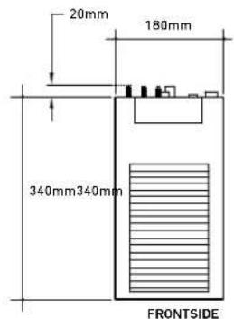


Diagram 3
Installing the dispenser XL, XT, XR.
IMPORTANT: This Billi appliance is to be installed by a licensed trades person in accordance with AS/NZS 3500.1 and AS/NZ 3500.2 and in compliance with applicable state regulatory requirements. For correct operation of this appliance, it is essential to observe the manufacturer's instructions.
1. Install Dispenser Assembly
Determine position of dispenser mounting hole in sinktop or benchtop. Dispenser base template (Diagram 4) may be cut out and used to assist in correct positioning. Refer to Diagram 2 for clearances allowed. Hole size required is ø32mm.
Stainless Steel Sinktop
A suitable 35mm hole punch (Part no: 857901) is available as an accessory from Billi Australia Pty Ltd. If possible, cut hole with die mounted below the sinktop surface so that burr is pulled downwards. Alternatively, remove burr and radius edge of hole with fine file. This allows barbed dispenser mount to slide smoothly into mounting hole.
Timber/Laminate Benchtop
Maximum benchtop thickness is 50mm. Cut 32mm hole in appropriate position*. When drilling through a particle board bench top, take care to avoid a large chip breaking away as drill breaks through underside surface. We recommend drilling a small pilot hole through benchtop, partially drilling the 32mm hole from underneath and then completing drilling the hole from above. The large 30mm washer supplied may be used to secure barb where underside particle board bench top has chipped away.
* For stone or granite bench tops you will require a certified stone mason to pre-drill the hole.
2. Activate Dispenser Swivel Feature
To activate the swivel feature of your dispenser, you will need to remove the locking piece from the dispenser base. Simply push out the piece as show in Diagram 5. This will allow the tap to move 45 degrees to the left and right.
3. Fit Dispenser Base
a. Cut a 32mm hole in sinktop or benchtop. Remove burr if protruding upwards.
b. Push barbed mounting shaft through mount hole.
c. Insert barb locking bush as shown in Diagram 6. Finger tighten nut.
d. Ensure barb is centred in mount hole before tightening. Check position of base ring and gasket.
e. Moderately tighten locking nut using multigrips or spanner. Take care to avoid overtightening nut which may break the plastic threaded shaft.
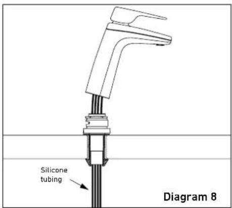
f. Place large D washer over thread as shown in Diagram 7.
g. Cut off excess threaded shaft with a hacksaw, using washer as a cutting guide. (Diagram 7)
IMPORTANT: Remove burrs and check internal bore is completely smooth.
4. Fit Dispenser Head Assembly
a. Feed dispenser tubing and loom through centre hole in the following order:
i. Dispenser power cord.
ii. Silicone tubes.
b. Gently pull hoses from under the bench top, do not attempt to force tubing through with a pointed object as silicone tube is easily punctured. Check tubing is not kinked or twisted.
c. Turn dispenser head assembly to approximately 60° from the straight ahead position of dispenser base. Slide head assembly onto base assembly whilst gently pulling tubing downwards from underneath to prevent tubing bunching and kinking. Mounting lugs will pass nut and slide down the 3 grooves on the swivel bearing.
d. Once fully down, turn dispenser to straight ahead position. Fit chrome plated M4 retaining screw to lower rear threaded hole and tighten using the allen key supplied. If swivel feature activated check dispenser now swivels smoothly 45^ in each direction.


natural_image
Technical line drawing of a mechanical component with an arrow indicating assembly direction (no text or symbols)

Additional installation – XR.
Flush mount remote panel.
Determine Remote Panel Location
Dimensions and layout are shown in diagram 9. Panel can be installed on a wall, benchtop or even inside a cupboard Minimum cut out dimensions are 121mm height x 70mm width. Minimum depth must be 20mm.
Cut out cavity into the plaster wall.
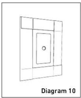
Ensure the cable is pre-installed into the flush mount bracket before plastering.
Place the flush bracket into the plaster wall with the cable gap facing towards the ground.
Installing the Remote Panel
Cable must be protruding out of the bottom of bracket – see diagram 9.
Tape up the cable terminals before plastering process – see diagram 10.

natural_image
Simple line drawing of a 3D rectangular frame with a central circular hole, labeled 'Diagram 10' below (no text or symbols on the diagram itself)Plaster and Paint
Start plastering as required.
Wait for the plaster to dry before cleaning the bracket.
Use a light sandpaper to give smooth finish on the drywall.
Then paint as required.
Completing Installation
Take the tape off the cable connector and plug it into the panel – see diagram 11
The panel and bracket are magnetic. Upon install, the magnets will pull together and secure the module into place in place – see diagram 11.
Installation is finished – see diagram 12.
Magnetic remover tool may be required again. Do not throw away.


Additional installation – XR.
Proud mount remote panel.
Determine Remote Panel Location
Cut out cable access hole in the desired location.
Hole size must be Width 25mm x Height 45mm – see diagram 13.
Drill a pilot hole using bracket as a template. The template could also be used as a guide to cut into the plaster.
Install Mount Bracket
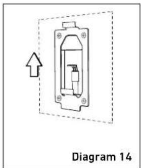
Fasten the mount bracket on to the wall using phillips head screwdriver (ensure the spring clips are facing up) – see diagram 14.

natural_image
Diagram of a mechanical device with an arrow indicating upward motion, labeled 'Diagram 14' (no text or symbols on the diagram itself)Install Cabling
Feed the cable through pre cut hole.
Screw and fasten the cable strain bracket to the back of remote tap module.
Secure the tap module by sliding it onto the previously installed bracket
- see diagram 15.
Completing Installation
Ensure panel is secured.
Clean up any excess plaster.
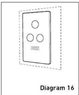
Installation is finished – see diagram 16.

Installing underbench module. XL, XT, XR.
1. Flush Water Supply
Flush water supply pipework before installing the underbench unit by connecting 600mm flexible braided hose to the supply tap and running water into a bucket. Blockages/unit malfunction caused by debris are not covered under warranty.
2. Install Underbench Unit
Take care to observe minimum clearances. Ensure there is adequate access to service the unit, taking into account the tube lengths and space available Refer Diagram 1, page 2.
3. ConnectDispenserTubing
and Electrical Plug
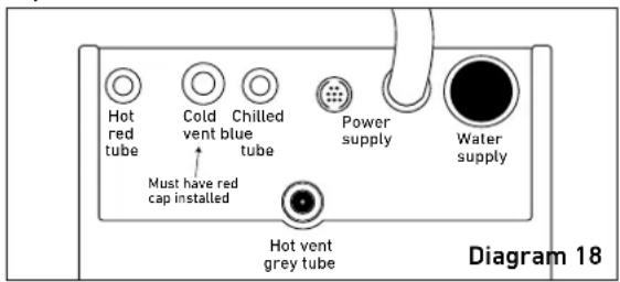
Connect all tubing as shown in Diagram 17 & 18. Ensure correct orientation of dispenser power plug before insertion. Trim tubes to correct lengths using plastic tube cutter. Do not leave excess tubing which will sag, trapping water. Fit spring clamps supplied to retain silicone rubber tubing to barbed fittings.
IMPORTANT: Boiling outlet (red), vent tube (grey) must not be kinked and must be installed with a continual fall and no sag.

Top View
Commissioning.
1. Turn On the Water Supply
Turn on water supply and ensure that there are no leaks. Remove front panel of unit and remove packing foam from under filter canister. Ensure filter canister is securely locked back into place. Replace front panel.
2. Power On
When power is applied the system checks the water level in the hot tank and if empty (below the low level sensor) then the unit will enter the boiling point calibration mode. This will normally only occur the first time a new system is turned on.
On power ON, if the hot tank level sensor is above the low level sensor, the unit will enter its normal operating mode at full power. This will happen when the system has been installed and used at least once.
IMPORTANT: On initial power up, leave the unit for 10 minutes before attempting user setup.
Boiling Point Calibration
The hot tank will first fill to the height of the low level sensor. The water is then heated until it reaches boiling point. The unit will continue to boil for up to 30 seconds while the temperature sensor calibrates.
WARNING: and small amounts of hot water may be discharged from the taps and vent during this period.
While calibration is underway the hot water indicator (red) will double blink rapidly. The hot water set point is calibrated .5°C below the boiling point. Once calibrated the unit will resume normal operations and the calibration data is saved. The unit will not re-calibrate under normal circumstances. If a repeated calibration is required the following procedure should be followed:
- turn the water supply off
– run the hot water until the hot tank is empty - turn the power off for 5 seconds, then on again
- turn water supply on
– the unit will then re-calibrate its boiling point.
Re-check Connections for leaks Explain Operation to user.
INSTALLATION AND
COMMISSIONING CHECKLIST
☐ Filter packing foam removed from under filter cannister.
□ Dispenser mounted securely.
☐ Dispenser swivels 45° in each direction
– Locking piece is removed
☐ Water main flushed before connection to unit.
☐ Tubing is cut to correct lengths and not kinked or sagging. Red, grey and blue silicone tubes have a continual fall.
□ Tubing secured correctly.
☐ Unit connected to COLD water supply.
☐ Correct air clearances around unit.
☐ Power circuit fitted with an RCD – earth leakage protection device.
□ Power cord connected to wall outlet.
□ Sawdust cleaned out of cupboard area.
☐ Initial program settings correctly set for dispenser tube length.
☐ Unit heating and cooling (after initial fill). Red and blue dispenser icons flashing (or on continually when reached temperature).
□ Boiling and chilled water flow correct.
□ Unit installed the correct way.
☐ Cold vent outlet has red cap installed (Diagram 18).
If any difficulties arise contact
Billi Australia Pty Ltd: Phone 1800 812 321 (Free call).
Validate your warranty online at www.billi.com.au
For information on our filtration and service contracts please contact Billi Customer Service on 1800 812 321 or service@billi.com.au.
For continued safety of this appliance it must be installed, operated and maintained in accordance with the manufacturer's instructions.
— Your appliance should be installed by a suitably qualified tradesperson.
— For correct operation of this appliance it is essential to observe the instructions as outlined in this booklet.
— Do not use this appliance with water that is microbiologically unsafe or with water of unknown quality without adequate disinfection before or after the system. Systems certified for cyst reduction may be used on disinfected water that may contain filterable cysts.
— Filter replacement must be performed at intervals of not more than 12 months.
— Use this appliance only as directed in these instructions and only for its designed purpose.
— This appliance is not intended for use by persons (including children) with reduced physical, sensory or mental capabilities, or lack of experience and knowledge, unless they have been given supervision or instruction concerning use of the appliance by a person responsible for their safety.
— Children should be supervised to ensure that they do not play with the appliance.
—DANGER: The operation of the thermal cut-out indicates a possibly dangerous situation. Do not reset the thermal cut-out until the water heater has been serviced by a qualified person.
—WARNING: Do not connect any restrictor or pressure relief device to the vent pipe of this water heater if installed.
— If the supply cord is damaged, it must be replaced by the manufacturer, its service agent or similarly qualified persons in order to avoid a hazard.
— New hose-sets supplied with the appliance are to be used and old hose-sets should not be re-used.
Billi™
Billi Australia Pty Ltd
42 Lucknow Crescent, Thomastown
Victoria 3074 Australia
Telephone +61 3 9469 0400
Facsimile +61 3 9469 0499
www.billi.com.au
Designed and manufactured in Australia.
As Billi Australia Pty Ltd has a policy of continual improvement, all details are subject to change without notice. All goods are sold subject to our published terms and conditions. Billi is a registered trademark. 0618


- Installation requirements XL, XT, XR.
- Components for Billi Eco
- Additional Components - XR
- Remote panel kit
- Determine Unit Location
- Water Supply
- Ventilation
- Power Requirements
- Installing the dispenser XL, XT, XR.
- Install Dispenser Assembly
- Stainless Steel Sinktop
- Timber/Laminate Benchtop
- Activate Dispenser Swivel Feature
- Fit Dispenser Base
- Fit Dispenser Head Assembly
- Additional installation – XR.
- Flush mount remote panel.
- Determine Remote Panel Location
- Installing the Remote Panel
- Plaster and Paint
- Completing Installation
- Proud mount remote panel.
- Install Mount Bracket
- Install Cabling
- Installing underbench module. XL, XT, XR.
- Flush Water Supply
- Install Underbench Unit
- ConnectDispenserTubing
- and Electrical Plug
- Commissioning.
- Turn On the Water Supply
- Power On
- Boiling Point Calibration
- INSTALLATION AND
- COMMISSIONING CHECKLIST
- Billi™
Brand : Billi
Model : Eco
Category : Water filter