LBH600A-P-12 - Network switch Black Box - Free user manual and instructions
Find the device manual for free LBH600A-P-12 Black Box in PDF.


| Product Type | Heavy Duty Edge Switch (Managed/Unmanaged) |
| Model | LBH600A-P-12 |
| Ports | 6 x 10/100 RJ-45 (Copper) with auto-MDIX |
| Fiber Ports | None (this model is all copper) |
| Dimensions (W x H x D) | 3.0 in x 3.7 in x 1.7 in (7.6 cm x 9.4 cm x 4.3 cm) |
| Weight | 13 oz (370 g) (unit only) |
| Power Supply | External AC adapter (100-240 VAC, 47-63 Hz) output 12 VDC, 2 A; or direct DC 12 VDC (8-15 VDC) via terminal block |
| Power Consumption | 7.0 W typical, 9.0 W max |
| Operating Temperature | -40°C to 75°C (Extreme rated, DC power) |
| Storage Temperature | -40°C to 85°C |
| Humidity | 5% to 95% (non-condensing) |
| Enclosure | Rugged sheet metal (steel), closed case for dirt/ moisture resistance |
| Switching Technology | Store-and-forward, non-blocking |
| MAC Address Table | 2K entries |
| Packet Buffer | 128 KB dynamically shared |
| LED Indicators | PWR, 10/100 (speed per port), LK/ACT (link/activity), F/H (fiber duplex - not on this model) |
| Mounting Options | Panel mount (clips included), DIN-rail (bracket optional), 19" rack tray (optional) |
| Alarm Contact | Hardware-operated NC relay (opens on power loss) - standard on Extreme models |
| Regulatory Approvals | UL 60950, cUL, CE, FCC Part 15 Class A, NEBS L3, ETSI, NEMA TS-2, IEEE 1613 |
| MTBF | Over 15 years (Telcordia method) |
| Warranty | Standard Black Box warranty (check with supplier) |
Frequently Asked Questions - LBH600A-P-12 Black Box
User questions about LBH600A-P-12 Black Box
0 question about this device. Answer the ones you know or ask your own.
Ask a new question about this device
Download the instructions for your Network switch in PDF format for free! Find your manual LBH600A-P-12 - Black Box and take your electronic device back in hand. On this page are published all the documents necessary for the use of your device. LBH600A-P-12 by Black Box.
USER MANUAL LBH600A-P-12 Black Box
© Copyright 2005. Black Box Corporation. All rights reserved.
1000 PARK DRIVE • LAWRENCE, PA 15055-1018 • 724-746-5500 • FAX 724-746-0746

BLACK BOX
NETWORK SERVICES
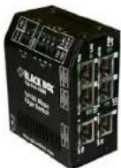
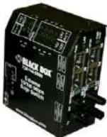
July 2005
LBH150A(AE) -H, -P
LBH240A(AE) -H. -P
LBH600 A(AE) -H, -P
Heavy Duty Edge Switches
CUSTOMER
SUPPORT
INFORMATION
Order toll-free in the U.S. 24 hours, 7 A.M. Monday to midnight Friday: 877-877-BBOX
FREE technical support, 24 hours a day, 7 days a week: Call 724-746-5500 or fax 724-746-0746
Mail order: Black Box Corporation, 1000 Park Drive, Lawrence, PA 15055-1018
Web site: www.blackbox.com • E-mail: info@blackbox.com
Black Box Heavy Duty Edge Switches Installation and User Guide (07/05)
BLACK BOX ^® Series
Heavy Duty Edge Switches
Installation and User Guide
Trademarks
Ethernet is a trademark of Xerox Corporation
NEBS is a trademark of Telcordia Technologies
UL is a registered trademark of Underwriters Laboratories
Important: The LBHXXX-Series 10/100 Mb/s Edge Switches contains no user servicable parts. Attempted service by unauthorized personnel shall render all warranties null and void. If problems are experienced with
render an warranties null and void. If problems are experienced with
LBHXXX 10/100 Mb/s Edge Switch products, consult Section 5.
Troubleshooting, of this User Guide.
Copyright © 2005 BLACK BOX® Corporation. All rights reserved. No part of this publication may be reproduced without prior written permission from Black Box, Inc.
Printed in the United States of America.
Black Box Heavy Duty Edge Switches Installation and User Guide (07/05)
Contacting Black Box Corporation
Please use these mailing address and phone and fax numbers:
Black Box Corporation
1000 Park Drive
Pittsburgh, PA 15055
Phone: (724) 746-5500
Fax: (724) 746-0746
E-mail: info@blackbox.co
Black Box Heavy Duty Edge Switches Installation and User Guide (07/05)
FEDERAL COMMUNICATIONS COMMISSION AND
CANADIAN DEPARTMENT OF COMMUNICATIONS RADIO FREQUENCY INTERFERENCE STATEMENTS
This equipment generates, uses, and can radiate radio frequency energy and if not installed and used properly, that is, in strict accordance with the manufacturer's instructions, may cause interference to radio communication. It has been tested and found to comply with the limits for a Class A computing device in accordance with the specifications in Subpart B of Part 15 of FCC rules, which are designed to provide reasonable protection against such interference when the equipment is operated in a commercial environment. Operation of this equipment in a residential area is likely to cause interference, in which case the user at his own expense will be required to take whatever measures may be necessary to correct the interference.
Changes or modifications not expressly approved by the party responsible for compliance could void the user's authority to operate the equipment.
Black Box Heavy Duty Edge Switches Installation and User Guide (07/05)
This digital apparatus does not exceed the Class A limits for radio noise emission from digital apparatus set out in the Radio Interference Regulation of the Canadian Department of Communications.
Certification Notice for
Equipment Used in Canada
The Canadian Department of Communications label identifies certified equipment. This certification means that the equipment meets certain telecommunications-network protective, operation, and safety requirements. The Department does not guarantee the equipment will operate to the user's satisfaction.
Before installing this equipment, users should ensure that it is permissible to be connected to the facilities of the local telecommunications company. The equipment must also be installed using an acceptable method of connection. In some cases, the company's inside wiring associated with a single-line individual service may be extended by means of a certified connector assembly (extension cord). The customer should be aware that compliance with the above conditions may not prevent degradation of service in some situations.
Repairs to certified equipment should be made by an authorized Canadian maintenance facility—in this case, your supplier. Any repairs or alterations made by the user to this
Black Box Heavy Duty Edge Switches Installation and User Guide (07/05)
equipment, or equipment malfunctions, may give the telecommunications company cause to request the user to disconnect the equipment.
Users should ensure for their own protection that the electrical ground connections of the power utility, telephone lines, and internal metallic water pipe system, if present, are connected together. This precaution may be particularly important in rural areas.
CAUTION:
Users should not attempt to make such
connections themselves, but should contact
the appropriate electric inspection authority,
or electrician, as appropriate.
The LOAD NUMBER (LN) assigned to each terminal device denotes the percentage of the total load to be connected to a telephone loop which is used by the device, to prevent overloading. The termination on a loop may consist of any combination of devices, subject only to the requirement that the total of the load numbers of all the devices does not exceed 100.
Black Box Heavy Duty Edge Switches Installation and User Guide (07/05)
TABLE OF CONTENTS
Page
1.0 SPECIFICATIONS (HEAVY-DUTY EDGE SWITCHES) ...... 1
1.1 Technical Specifications .... 1
1.2 Summary of models and descriptions.... 10
2.0 INTRODUCTION 12
2.1 Inspecting the Package and the Product.... 12
2.2 Product Description 13
2.3 Frame Buffering and Latency 22
2.4 Features and Benefits.... 26
2.5 Applications for Heavy-Duty LBHXXX Edge Switches.... 29
3.0 INSTALLATION....37
3.1 Locating the Edge Switch Unit 37
3.2 LH1505-RACK for Rack Mounting of Heavy-Duty LBH Switches. 38
3.3 LH1505-RACK-1-9V and LH1505-RACK-2-9V 40
3.4 DIN-Rail mounting option....41
3.4 Power Requirements, Power Supply Types.... 42
3.5 Powering the LBHXXXA(E)-H and -P (DC internal)....44
Black Box Heavy Duty Edge Switches Installation and User Guide (07/05)
3.6 DC Power Terminals: "+" , "-", gnd.... 46
3.7 LBHXXXA(E)-H and -P Series, DC-powered.... 47
3.8 Connecting Ethernet Media 48
3.8.1 Connecting Twisted Pair....50
3.8.2 Connecting Fiber Optic ST-type, "twist-lock" 50
3.8.3 Connecting Fiber Optic SC-type, "Snap-In" 51
3.8.4 Connecting Single-Mode Fiber Optic 52
3.8.5 Power Budget Calculations.... 53
3.8.6 Connections to NICs 55
4.0 OPERATION....56
4.1 Dual-Speed Functionality, and Switching 56
4.2 Auto-cross (MDIX), 58
4.3 Dual LEDs, Front-panel and side-panel.... 59
4.4 Hardware operated Alarm Contact 60
5.0 TROUBLESHOOTING 61
5.1 Before Calling for Assistance 62
5.2 When Calling for Assistance 63
Black Box Heavy Duty Edge Switches Installation and User Guide (07/05)
5.3 Return Material Authorization (RMA) Procedure 65
Revisions
Rev A 06/05: Initial release of this user manual for Heavy Duty Edge Switches
Black Box. reserves the right to change specifications, performance characteristics and/or model offerings without notice.
Black Box ^® Heavy Duty Edge Switches Installation and User Guide(07/05)
1.0 SPECIFICATIONS (Heavy-Duty Edge Switches)
1.1 Technical Specifications
Ports Performance
When a port is operating at 100Mbps:
Data Rate: 100Mbps
When a port is operating at 10 Mbps:
Data Rate: 10 Mbps
Network Standards
100Mb: Ethernet IEEE 802.3u, 100BASE-TX, 100BASE-FX
10 Mb: Ethernet IEEE 802.3, 10BASE-T
Auto-sensing for speed: IEEE 802.3u
Packet-Processing Between Domains
Filter and Forward Rate from 100Mbps ports: 148,800 pps max
Filtering and Forwarding Rate from 10 Mbps ports: 14,880 pps max.
Processing type: Store and Forward, non-blocking
Auto-learning: 2K address table
Address buffer age-out time: 300 sec.
Packet buffers memory: 128KB, dynamically shared on all domains
Black Box ^® Heavy Duty Edge Switches Installation and User Guide(07/05)
| Latency (not including packet time): | 100 to 10 Mbps: 5μs |
10 to
Path Delay Value: 50 BT on all ports
LLL(Link-Loss-Learn): Factory default is activated on port 1 and 2
(allow to flush the internal address buffer, and qualify to use STP/RSTP for
faster recovery in ring topology)
Maximum Ethernet Segment (or Domain) Lengths
10BASE-T (Unshielded twisted pair) - 100 m (328 ft)
100BASE-TX (CAT 5 UTP) - 100 m (328 ft)
100BASE-FX, half-duplex: (multi-mode) - 412 m (1350 ft)
100BASE-FX, full-duplex: (multi-mode) - 2 km (6,562 ft)
100BASE-FX, half-duplex: (single-mode) - 412 m (1350 ft)
100BASE-FX, full-duplex: (single-mode) - 20 km (65,620 ft)
100BASE-FX, full-duplex: (single-mode, long reach) - 40 km (131,240 ft)
Black Box ^® Heavy Duty Edge Switches Installation and User Guide(07/05)
Operating Environment
LBHXXXA(E): 32°F to 104°F (0°C to 40°C)
LBHXXXA(E)-II: -13°F to 140°F (-25°C to 60°C) Long term per agency tests (UL).
-40°F to 149°F (-40°C to 85°C) Short term per IEC Type tests.
LBHXXXA(E)-P: -40°F to 167°F (-40°C to 75°C) Long term per agency tests (UL).
-58°F to 212°F (-50°C to 100°C) Short term per IEC Type tests.
Storage Temperature.
All models: -40^ to 160^ ( -40^ to 85^ )
Cold Start:
LBHXXXA(E)-H to -20°C
LBHXXXA(E)-P to -40°C
Ambient Relative Humidity: 5% to 95% (non-condensing)
Altitude (All models): -200 to 5000ft. (-60 - 15,000 m)
Conformal Coating (optional) for humidity protection
Note: II and Extreme models are designed for NEBS compliance, including, vibration, shock and altitude.
Black Box ^® Heavy Duty Edge Switches Installation and User Guide(07/05)
Packaging:
Enclosure: Rugged sheet metal (Steel).
Dimensions of the Switch unit:
3.7 in H x 3.0 in W x 1.7 in D (9.4 cm x 7.6 cm x 4.3 cm)
Weight: all models: 13 oz. (370g);
Power supply, A, and AE: 5.8 oz (165g)
A-H, and AE-H: 5.8 oz (165g)
A-P, and AE-P: 7.9 oz (225g)
Cooling Method:
Convection on the office model. The Hardened (H) factory floor and Extreme (P) temperature un-controlled location models have closed cases to withstand dirt and use special thermal techniques to transfer heat to the outside of the case for cooling.
ALARM RELAY Terminal Block, H and P models only, two screw terminals:
Internal 60VA relay contact: Open for power Off, closed for power On (Hardware).
Black Box ^® Heavy Duty Edge Switches Installation and User Guide(07/05)
POWER SUPPLY
These products are intended to be supplied by a Listed, Direct Plug-In power unit, marked "Class 2", or a Listed ITE Power Supply, marked "LPS", which has suitably rated output voltage (i.e. 9vdc, 12vdc, 24vdc, 48vdc), and suitably rated output current (i.e. 100mA to 500mA). When connected to a 48V centralized DC source, these products shall be provided with a Listed 5 A DC fuse in the supply circuit.
Direct DC POWER SUPPLY : built-in terminal
block for +, -, ground along with 12VDC jack
12V DC internal (range 8.0 to 15V DC),
24V DC internal (range 10 to 36V DC),
-48V DC internal (range 30 to 60V DC),
AC POWER SUPPLY ( using an external power adapter):
All models have an (8-15)VDC output with 6ft long cord and a 2.5mm center + jack. The external AC power supplies are temperature rated to match the Edge Switch ratings.
Black Box ^® Heavy Duty Edge Switches Installation and User Guide(07/05)
Office Models Ratings (0 to 40°C)
North America (A) models. Input: direct plug-in 95-125vac at 60 Hz.
Output:12vdc, 1Amps
International (AE) models. Input: 240vac at 50Hz with TEC 320 connector for the user supplied AC power cord.
Output:12vdc, 1Amps
Factory Floor Models (H) Ratings (-25 to 60°C)
North America (A-H) models. Hardened, factory floor temperature rated. Input: 6ft AC 3power cord to IEC 320 connector on the 100-240vac 47-63Hz external power adapter.
Output:12vdc, 1.25Amps
International (AE-II) models. Factory floor temperature rated. Input: IEC 320 connector on the 100-240vac 47-63Hz external power adapter. Requires a user supplied power cord Output:12vdc, 1.25Amps.
Temperature un-controlled Extreme (P) Ratings (-40 to 75°C)
North America (A-P) models. Outdoor temperature rated. Input: 6ft AC power cord to IEC 320 connector on the 100-240vac 47-63Hz external power adapter.
Output:12vdc, 2Amps.
Black Box ^® Heavy Duty Edge Switches Installation and User Guide(07/05)
International (AE-P) models. Outdoor temperature rated. Input: IEC 320 connector on the 100-240vac 47-63Hz external power adapter. Requires a user supplied power cord. Output: 12vdc, 2Amps.
Note: LH1505-CK - For Hardened or Extreme -24VDC unit only for dual DC power (sold separately). See 3.6.
Power Consumption: See Section 3.6.
Note 1: the 12V DC jack can be used for dual source DC input using an AC adapter and the DC terminal block. Power supply protection is provided by internal diodes.
Note 2: The Direct DC power floats. The user may ground either “+” or “-” if desired. Power Consumption, all models: 7.0 watts typical, 9.0 watts max.
Port Connectors:
RJ-45 Ports: support 100BASE-TX and 10BASE-T with auto-cross (MDIX). They are shielded 8-pin female connectors for shielded (STP) and unshielded (UTP) Cat 3, 4, 5 cable.
Black Box ^® Heavy Duty Edge Switches Installation and User Guide(07/05)
Fiber optic port: supports 100Base-FX with a "fiber flavor" choice of multimode SC, ST, LC or MTRJ or single mode SSC, SSCL, SST or SLC connectors. (By default factory settings is at "Full" duplex on fiber ports)
LED Indicators (Front)
POWER: Steady ON when power applied
10/100: Steady ON for 100Mbps; OFF for 10 Mbps(copper ports only)
LK/ACT: Steady ON for LINK (LK) with no traffic, BLINKING indicates port is transmitting / receiving (ACT).
F/H: Steady ON for full-duplex, OFF for half-duplex (Fiber port only)
Mounting options
Metal mounting clips for panel mounting: included
DIN-Rail mounting option: Model # DIN_RAIL_MC2 (see Section 3.4)
Rack-mount option: Model # LII1505-RACK (see Section 3.2)
Depth: 6.0", width: 17" Height: 2.25" (15cm D x 43cm W x 5.7cm H)
S
Black Box ^® Heavy Duty Edge Switches Installation and User Guide(07/05)
Mean Time Between Failure (MTBF) - over15 years, Telcordia (Bellcore) Method
Agency Approvals and Standards Compliance:
UL Listed (UL 60950), cUL, CE, Emissions meets FCC Part 15 Class A. NEBS L3 and ETSI compliant.
Hardened and Extreme models: IEEE 1613 Env. Std for Electric Power Substations
Extreme models: NEMA TS-2 and TEES for traffic control equipment
Extreme models: designed for UL 2043 above-the-ceiling installation
IEC61850 EMC and Operating Conditions Class C Power Substations
Made in USA
Black Box ^® Heavy Duty Edge Switches Installation and User Guide(07/05)
1.2 Summary of models and descriptions
Note: The LBH150, LBH240 and LBH600 model # consists of the base unit, for domestic power supply add A, for international power supply add AF, fiber interface xx and the dc power option yy. (see note for xx and yy) In three different temperatures range Standard, Hardened and Extreme.
Standard for office and wiring closet (0 to 40C) using an external AC power supply.
LBH150A(E)-xx = one 100Mb fiber port + five 10/100 RJ-45
LBH240A(E)-xx = two 100Mb fiber port + four 10/100 RJ-45
LBH600A(E) = six 10/100 RJ-45
Hardened (H) for factory floor (-25 to 60C) using a direct DC (8-15VDC) and/or external AC hardened power supply (included).
LBH150A(E)-H-xx-yy = one 100Mb fiber port + five 10/100 RJ-45
L.BH240A(E)-II-xx-yy = two 100Mb fiber port + four 10/100 RJ-45
LBH600A(E)-H-yy = six 10/100 RJ-45
Extreme (P) for un-controlled (outdoor) (-40 to 75C) using direct DC (8-15VDC) and/or external AC Extreme power supply (included).
LBH150A(E)-P-xx-yy = one 100Mb fiber port + five 10/100 RJ-45
L.BH240A(E)-P-xx-yy = two 100Mb fiber port + four 10/100 RJ-45
LBH600A(E)-P-yy = six 10/100 RJ-45
10
Black Box ^® Heavy Duty Edge Switches Installation and User Guide(07/05)
Note: xx for fiber interface
“SC” = 100Basc-FX-SC: multi-mode fiber optic with SC type connector, 2km.
“SSC”=100Base-FX-SSC: single-mode fiber optic with SC type connector, 20km.
“SSCL”=100Base-FX-SSCL: single-mode fiber optic with SC type connector, 40km.
“ST” = 100Base-FX-ST: multi-mode fiber optic with ST type connector, 2km.
“SST” = 100Base-FX-ST: single-mode fiber optic with ST type connector, 2km.
“SLC”=100Base-FX-SLC: single-mode fiber optic with LC type connector, 15km.
“MT”=100Base-FX-MTRJ: multi-mode fiber optic with MTRJ type connector, 2km.
Note: yy for dc power options
“12” = 12 VDC
“24” = 24 VDC and HD and PD for DIN Rail mounts bracket included
“48” = -48 VDC
without the -yy unit is AC powered.
Accessories
LH1505 = 19" Rack-mount tray for LBH150, LBH240 and LBH600 Switch models, up to 8 units
Other Tray configurations with power supplies and power cabling included - See Section 3.3
LH1505-CK=Cable kit for 24VDC input power input jack for one of any 24VDC model
DIN-RAIL MC2 = Metal DIN-Rail mounting bracket for one Heavy-Duty LBH150, LBH240 and
LBH600 Switch, -See Section 3.4
Conformal Coating (for high humidity and "tropical" applications) - request quote.
2.0 INTRODUCTION
This section describes LBHXXX Series models, including appearance, features and typical applications.
2.1 Inspecting the Package and the Product
Examine the shipping container for obvious damage prior to installing this product; notify the carrier immediately of any damage which you believe occurred during shipment or delivery. Inspect the contents of this package for any signs of damage and ensure that the items listed below are included.
This package should contain:
1 LBHXXX Series Heavy-Duty Edge Switch unit,
1 External Power Supply, (not with DC powered models)
1 set Metal panel mounting clips and screws (2 each)
1 User Guide (this manual)
Black Box ^® Heavy Duty Edge Switches Installation and User Guide(07/05)
Remove the Black Box LBHXXX Series Edge Switches from the shipping container. Be sure to keep the shipping container should you need to ship the unit at a later date. In the event there are items missing or damaged contact your supplier. If you need to return the unit use the original shipping container. Refer to Section 5 Troubleshooting, for specific return procedures.
2.2 Product Description
Black Box Heavy-Duty Edge Switches (LBHXXX-Series) are designed as an Ethernet edge solution in industrial, military and un-controlled temperature applications, as well as an economical solution for the growing requirements of managed networks.
LBHXXX-Series, a six port versatile family of compact Edge switches, loaded with factory configurable fiber options and AC/DC power input options with Alarm terminal block and innovative packaging is ready to serve the needs of edge-of-the-network applications.
The Heavy-Duty (LBHXXX) family of Edge Switches have a wide breadth of port configurability and fiber port type options - six 10/100 copper ports or four 10/100 copper ports and two 100 Mb Fiber port or five copper ports with one 100Mb Fiber port
Black Box ^® Heavy Duty Edge Switches Installation and User Guide(07/05)
built in, covers the full range of application environments, with regular (office), Hardened (factory floor), and Extreme-rated (outdoor) versions. Extra features for Heavy-
Duty(LBHXXX) and extended temperature operation ranges are included selectively in the Hardened factory-floor and Extreme-rated outdoor models. The breadth of models and flavor of fiber port types offers the best price-to-value ratio for each user and installation.
The compact package is ideal for network edge installations, and is able to be conveniently Din rail mounted to suit any application.
The Black Box Edge switches include Link-Loss-Learn(LLL) feature (factory configurable on ports 1 and 2 to qualify for any redundant and self-healing managed network structures. The Link-Loss-Feature in LBHXXX-Series allows the Edge switches to flush the internal address buffers in milliseconds to permit a quick change in LAN packets flow, and pass the reconfiguration signal down the line to other ring switches in the redundant structure for faster recovery. Black Box Edge switches, combined with other
Black Box ^® Heavy Duty Edge Switches Installation and User Guide(07/05)
Black Box managed switches, running STP/RSTP. can often provide high availability Redundant LANs at economical cost.
The Heavy-Duty LBHxxx-Series regular-package units are for office
and indoor wiring closet environments. These are the economical base units in the
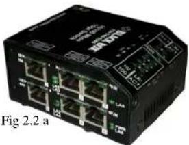
LBHxxxA Switch family. An external AC power supply for either North America (-d, 115vac 60Hz) or international (-I, 230vac, 50Hz) is included. The ambient temperature rating is 0°C to 40°C, office grade. Fig 2.2a LBH600A with SIX 10/100 RJ-45 only
natural_image
Black industrial network device with multiple ports and indicator lights (no visible text or symbols)A robust metal case with convection
cooling is featured. Metal mounting clips are included, and rack-mount tray options are available.
Black Box ^® Heavy Duty Edge Switches Installation and User Guide(07/05)
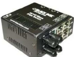
Fig 2.2 b Fig 2.2b (LBH150A-SC) left with four10/100 RJ-45 and two fiber 100Mb
natural_image
Exterior view of a black electronic device with multiple ports and connectors (no visible text or symbols)The Regular Heavy-Duty LBHXXX Edge Switches models (as shown in Fig 2.2.a, b,) units are for office and wiring closet environments and use an external AC power supply. A ventilated metal case for convection cooling is featured. Ambient operating temperature is 0^ to 40^ . Storage temperature rating is -40^ to 85^ . Metal clips are included for secure panel mounting and optional
DIN-Rail mounting. The regular models also has a rack-mount option via an MC-TRAY.
Black Box ^® Heavy Duty Edge Switches Installation and User Guide(07/05)
The regular model LBIIXXXA, includes Link-Loss-Learn, MDIX ports and the full range of fiber port options. The regular LBI1150A/LBI1240A model does not have options for
Alarm and DC power
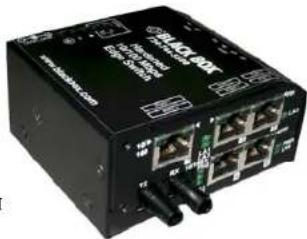
The Hardened labeled Heavy-Duty LBHXXXA-II Edge Switches H units (shown in Fig 2.2c & d) are designed for factory floor/Industrial applications. Using special thermal techniques and a scaled rugged metal case for heavy duty industrial applications, the Hardened LBHXXXA-H requires no air inflow for cooling, so the LBHXXXA-H resists dirt, moisture, smoke and ins
natural_image
Black electronic device with multiple ports and connectors (no visible text or symbols)Fig. 2.2.c Hardened LBH150A-H-ST
Black Box ^3 Heavy Duty Edge Switches Installation and User Guide(07/05)
The Heavy-Duty LBII150A-H/LBI240A-II Edge Switches, Hardened units are for
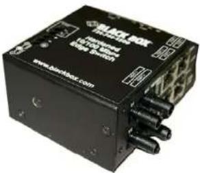
factory floor applications. The LBHXXXA-11
models are built with high-grade
components and are constructed using
special thermal techniques and a metal case
for heavy duty Fig. 2.2.d Hardened
LBH240A-H-ST industrial jobs.
In addition to a Hardened AC power option
and jack, terminals for internal DC power
choices at 8 to 15V, 24V or -48V DC are
included. The ambient temperature rating of -25 to 60C is for industrial use. No internal air flow is required for cooling, so it resists dust, dirt, moisture, smoke and insects. Mounting options include stand-alone panel-mounting, DIN-Rail, or rack-mount tray. Choices of
Black Box ^® Heavy Duty Edge Switches Installation and User Guide(07/05)
models for external AC or internal DC power are available. Ambient operating temperature
is -25^ to +60^ depending on the power source
used. Storage
temperature rating is -25^ to +85^ .
natural_image
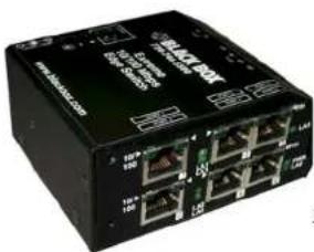
Black industrial network switch device with multiple Ethernet ports and indicator lights (no visible text or labels)Fig 2.2e & f,
Extreme
model
LBH240A-
P-ST
LBH600A-P
natural_image
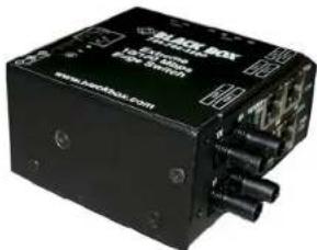
Black electronic device with ports and connectors, no visible text or symbols on bodyThe Extreme labeled Heavy-Duty
LBHXXXA(E)-P Edge Switches Extreme-rated units are
for temperature un-controlled applications (-40 to
75°C), typically located outdoors. The LBHXXXA(E)-P models are built with premium-grade
Black Box ^® Heavy Duty Edge Switches Installation and User Guide(07/05)
extended temperature components, and use similar thermal techniques as the LBHXXXA-II Hardened units. In addition to a Extreme-rated AC power option and jack, terminals for internal DC power choices at 8 to 15V, 24V or -48V DC are included. When used outdoors, the LBHXXXA-P should be protected from rain.
Mounting options include stand-alone panel-mounting, DIN-rail, or rack-mount tray. The LBHXXXA-P series (as shown in Fig. 2.2f & g) are Extreme rated units suitable for temperature un-controlled outdoor applications. Specially designed with premium-grade extended temperature components, the LBHXXXA-P units use similar thermal techniques to the LBHXXXA-H hardened units for cooling. Mounting options include panel-mounting, DIN-rail, or rack-mount tray. Choices of models for external AC or internal DC power are available. Ambient operating temperature is between -40^ to +75^ depending on the power source used. Storage temperature rating is between -40^ to +85^ .
Black Box ^® Heavy Duty Edge Switches Installation and User Guide(07/05)
All the Extreme and hardened models also come along with hardware operated Alarm terminal block for providing extra reliability to the unit. The Alarm feature allows the LBHXXX heavy duty users to be aware and to monitor any internal power failure. See section 44 for details.
The front side of the unit has four/five twisted-pair 10/100Mb switch ports and one/two 100Mb fiber port. All the RJ-45 ports of the Heavy-Duty LBHXXX Edge switches support auto-cross (MDIX) operation under auto-negotiation mode. The Heavy-Duty LBHXXX provides switching among four 10/100 auto-negotiating copper ports and two 100Mb fiber ports which may be SC, ST, MTRJ or LC multi-mode or single-mode. The LBHXXX's breadth of fiber options and well as temperature options provide many networking options and solutions in a very small footprint.
Two sets of LEDs to indicating the operating status of ports are mounted on the top and front (for extra viewing advantage while rack-mounted). For each port, there are Link and Activity (LK/ACT) LED's on the top indicating that the media cables are
Fig 2.2c
Black Box ^® Heavy Duty Edge Switches Installation and User Guide(07/05)
connected correctly and showing, by blinking, when there is traffic. The LK/ACT LED's are repeated on the front as 1 (port 1)...6 (port 6), whereas on the side as LA1...LA6. There is another set of LEDs on the front for 10 or H and 100 or F, to indicate the data rate as well as a set to indicate duplex for ports 1 and 2 only. 10/100 indicates the speed for copper ports, whereas F/H indicates Full and Half duplex for fiber ports only.
There is a power (PWR) LED to indicate that the unit is turned ON. The fiber ports on the LBHXXX Edge switches are multi-mode or single-mode with an SC, ST or small form factor connector (MTRJ multi mode or LC single-mode).
The external DC power plug connector and/or "jack" and the internal DC input terminal is provided on the rear of the unit.
2.3 Frame Buffering and Latency
The Heavy-Duty LBHXXX Series Edge Switches are store-and-forward switches. Each frame (or packet) is loaded into the Switch's memory and inspected before forwarding can occur. This technique ensures that all forwarded frames are of a valid
Black Box ^® Heavy Duty Edge Switches Installation and User Guide(07/05)
length and have the correct CRC, i.e. they are good packets. This eliminates propagation of bad packets, enabling all of the available bandwidth to be used for valid information.
While other switching technologies such as "cut-through" or "express" impose minimal frame latency, they will also permit bad frames to propagate to the Ethernet network. The "cut-through" technique permits collision fragment frames, which are a result of late collisions, to be forwarded--which add to the network traffic. There is no way to filter frames with a bad CRC (the entire frame must be present in order for CRC to be calculated). Since collisions and bad packets are more likely when traffic is heavy, store-and-forward switch technology enables more bandwidth to be available for good packets when the traffic load is greatest.
To minimize the possibility of dropping frames on congested ports, each Heavy-Duty LBHXXX Edge Switch dynamically allocates buffer space from 128KB memory pool, ensuring that heavily used ports receive very large buffer space for packet storage.
Black Box ^® Heavy Duty Edge Switches Installation and User Guide(07/05)
(Many other switches have their packet buffer storage space divided evenly across all ports, resulting in a small, fixed number of packets to be stored per port. When the port buffer fills up, dropped packets result.) This dynamic buffer allocation provides the capability for the maximum resources of the Heavy-Duty LBHXXX Edge Switches unit to be applied to all traffic loads, even when the traffic activity is unbalanced across the ports. Since the traffic on an operating network is constantly varying in packet density per port and in aggregate density, the Heavy-Duty LBHXXX Edge Switches are constantly adapting internally to provide maximum network performance with the least dropped packets.
When the Switch detects that its free buffer queue space is low, the Switch sends industry standard (full-duplex only) PAUSE packets out to the devices sending packets to cause "flow control". This tells the sending devices to temporarily stop sending traffic, which allows a traffic catch-up to occur without dropping packets. Then, normal packet buffering and processing resumes. This flow-control sequence occurs in a small fraction of a second and is transparent to an observer.
Black Box ^® Heavy Duty Edge Switches Installation and User Guide(07/05)
Another feature implemented in Heavy-Duty LBHXXX Edge Switches is a collision-based flow-control mechanism (when operating at half-duplex only). When the Switch detects that its free buffer queue space is low, the Switch prevents more frames from entering by forcing a collision signal on all receiving half-duplex ports in order to stop incoming traffic.
The latency (the time the frame spends in the Switch before it is sent along or forwarded to its destination) of the Heavy-Duty LBHXXX Edge Switches varies with the port-speed types. The length of the frame is a variable as it is with all store-and-forward switches. For 10 Mb-to-10 Mb, 10 Mb-to-100Mb or 100Mb-to-10 Mb forwarding, the latency is 15 microseconds plus the packet time of 10 Mb. For 100Mb-to-100Mb forwarding, the latency is 5 microseconds plus the packet time of 100Mb.
2.4 Features and Benefits
Full 100Mb or 10 Mb switching services for high performance Ethernet Black Box Heavy-Duty LBHXXX Switches provide Fast Ethernet switching on all ports. They perform high speed filter/forward operations on the traffic, giving each port's segment a full 100Mb (or 10 Mb) of bandwidth.
■ Reduces Network Costs and provide economical solution
Black Box Heavy-Duty LBHXXX Switches offer the ideal solution to efficiently and inexpensively connect a Twisted Pair and fiber network with 10Mb or 100Mb and help to expand the Ethernet network in a very convenient and economical way.
■ Choice of one or two100Mb Fiber option, more efficient
Designed as a multi-purpose media Edge Switch, the 100Mb fiber port allows the user to convert the media from copper to fiber and the other RJ-45 port can be used as diagnostic port or for more connectivity.
Black Box ^® Heavy Duty Edge Switches Installation and User Guide(07/05)
■ Installation is “Plug and Play”, operation is transparent to software The Black Box Heavy-Duty LBHXXX Switches operate as hardware switches, only forwarding those packets from each domain that are needed on the other domains. Internal address tables are self-learning, enabling users to change port connections or 10/100 domains without affecting operations.
■ Two sets of LEDs for viewing status from any angle.
Each LBHXXX Edge Switch is equipped with two sets (front and side) of LEDs to provide status information when viewed at almost any angle or mounting arrangement whether rack LH1505P-RACK or Din-Rail mounted.
Rugged metal case, Industrial grade
LBHXXX have a robust design and are packaged in a rugged sheet metal enclosure to ensure high reliability and durability even when placed in industrial or outdoor applications.
Black Box ^® Heavy Duty Edge Switches Installation and User Guide(07/05)
■ Qualified to use for temperature un-controlled “outdoor” application
The Black Box LBHXXXA(E)-P Extreme rated versions of Edge Switches have an ambient temperature rating between -40^ to +75^ for DC models and qualify for temperature un-controlled “outdoor” application.
■ Efficient Compact design, for all purpose convenient mounting
Featuring a compact steel case with an external AC and internal DC power supply, Black Box Heavy-Duty LBHXXX of Edge Switches can be installed in small spaces in cabinets, on table tops, in racks, walls or DIN-Rail mounted and in trays such as the Black Box LI11505P-RACK.
■ MDIX ports to eliminate cross-over cable while cascading All the Black Box Heavy-Duty LBHXXX Switches are featured with MDIX (auto-cross), which easily allow cascading with other Switch, Hubs or media Edges without using the cross-over cable.
Black Box ^® Heavy Duty Edge Switches Installation and User Guide(07/05)
■ Hardware operated Alarm terminal block for LBHXXXA(E)-H and LBHXXXA(E)-P
The Alarm contact option on LBIHXXXA(E)-II and LBIHXXXA(E)-P enables monitoring for internal power failure, and provides extra reliability to the hardened Switch
■ Link-Loss-Learn feature for faster recovery in redundant managed network
The LLL feature qualifies the Edge switches to actively work along with redundant network structure as a client switch and allow a faster recovery during ring break.
2.5 Applications for Heavy-Duty LBHXXX Edge Switches
Available in three “hardness” models (“office/wiring closet”, “Hardened”, “Extreme rated (outdoor)”), and hundreds of port-type combinations, Black Box Heavy-Duty LBHXXX Edge Switches fit very well in almost any environment to enable users to scale their networks quickly and cost effectively. The edge-of-the-network connectivity solutions
Black Box ^® Heavy Duty Edge Switches Installation and User Guide(07/05)
offered by Black Box Edge Switches provide convenient, economical, and reliable solutions as well as an active role on the managed redundant network setup for faster recovery. The compact Black Box Heavy-Duty LBHXXX assists fast expanding network requirements via providing edge support and reliability to the managed redundant network. The Dual-Speed and Dual-media functions support a mixed environment of 10 Mbps and 100Mbps users with copper and fiber media. The switched full duplex fiber ports also provide high bandwidths and longer distance support. The up-link feature of 100Mb fiber on Ports 1 and 2 enable easy expansion for the on-going demand of Ethernet networks. The 10/100Mbps auto-negotiating MDIX copper ports and the breadth of 100Mbps fiber ports enable easy interfacing with existing cable plant and equipment. Models of LBHXXX Edge Switches are available for even the most extreme temperatures. The LBHXXX's rugged case provides extra support in the harshest industrial environments. Link-Loss-Learn is an additional feature to provide the extra reliability to the redundant network and an economical solution for faster recovery, during the ring break.
Black Box ^® Heavy Duty Edge Switches Installation and User Guide(07/05)
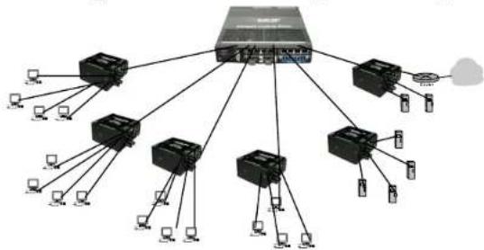
Example1. Supermarket application for LBHXXX- In this example, the supermarket required a Data Mining function to store all the transaction with an ongoing demand to expand the network. This need can be easily met using the economical Black Box LBHXXX Edge Switch. Additional functionality includes the ability to transfer data
flowchart
graph TD
    A["Server"] --> B["Switch 1"]
    A --> C["Switch 2"]
    A --> D["Switch 3"]
    A --> E["Switch 4"]
    A --> F["Switch 5"]
    A --> G["Switch 6"]
    A --> H["Switch 7"]
    A --> I["Switch 8"]
    A --> J["Switch 9"]
    A --> K["Switch 10"]
    B --> L["Device 1"]
    C --> M["Device 2"]
    D --> N["Device 3"]
    E --> O["Device 4"]
    F --> P["Device 5"]
    G --> Q["Device 6"]
    H --> R["Device 7"]
    I --> S["Device 8"]
    J --> T["Device 9"]
    K --> U["Device 10"]
across large distances with multi- or single-mode fiber while securing the LAN from EMI and wire tapping.
The LBHXXX's six ports in a small, reliable metal enclosure provide an effective solution to for transferring real-time transactions from the store to the storage device in the control room. The easily deployable through Din-rail option and the dual power source of flexibility along with flavor of fiber option for distance, the LBHXXX easily meets all the requirements of supermarket. The plug-n-play LBHXXX not only provides a reliable solution but also reduces operational costs significantly.
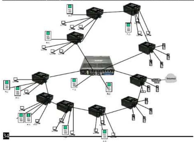
Example 2: LBHXXXA(E)-H and LBH100AE
In this industrial networking application, the new PLC units are deployed on a network expansion, and each PLC required one (or two for redundancy) Ethernet ports to carry status and control data to the control center. The LBHXXXA and LBH100A provide a good solution with their multiple options and hardened features. The two Fiber ports on the Edge switches are ideal for secure data communications over long distances. Built with high-grade components, efficient cooling techniques and having no openings for dirt to enter, the Heavy-Duty LBHXXX Edge Switches provide the very effective solution for this need. The LBH100A media converter switch offers additional and affordable fiber connectivity to the LBHXXXA(E)-H where needed. The sleek and reliable design of it not only being deployed easily in industrial environment but also provide an effective economical solution.
Black Box ^® Heavy Duty Edge Switches Installation and User Guide(07/05)
flowchart
graph TD
    A["Router"] --> B["Switch"]
    A --> C["Computer"]
    B --> D["Switch"]
    B --> E["Computer"]
    C --> F["Switch"]
    C --> G["Computer"]
    D --> H["Internet"]
    E --> H
    F --> H
    G --> H
    H --> I["Computer"]
    style H fill:#f9f,stroke:#333
Black Box ^® Heavy Duty Edge Switches Installation and User Guide(07/05)
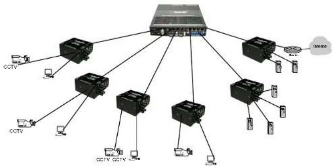
Example 3: LBHXXXA(E)-P: In this example, the Black Box LBHXXXA(E)-P Extreme Edge Switches are deployed to serve as a secure corporate or transportation surveillance system. CCTV cameras may be spread out over many miles in temperature un-controlled locations and with pan, tilt and zoom (PTZ) controlled through an Ethernet copper port. The premium Edge Switches provide two fiber segments for secure long distance (2-40km) communication while being installed in temperature un-controlled cabinets and allowing a full range of AC and DC power options. The four copper ports at the remote location provides access for other Ethernet equipment such as motion detectors or will act as a test port for maintenance personnel with up-link for access to a central LAN and central file servers. The application of video conferencing and capturing the events and transfer to the central location is coming out as a useful application in lots of location of traffic or industrial floor. The ideally-suited LBHXXXA(E)-P with its diversified features, premium-rated approvals and cost-effective solutions, make an ideal choice in outdoor environments.
Black Box ^® Heavy Duty Edge Switches Installation and User Guide(07/05)
flowchart
graph TD
    A["Central Server"] --> B["CCTV"]
    A --> C["CCTV"]
    A --> D["CCTV"]
    A --> E["CCTV"]
    A --> F["CCTV"]
    A --> G["CCTV"]
    A --> H["CCTV"]
    A --> I["CCTV"]
    A --> J["CCTV"]
    A --> K["CCTV"]
    A --> L["CCTV"]
    A --> M["CCTV"]
    A --> N["CCTV"]
    A --> O["CCTV"]
    A --> P["CCTV"]
    A --> Q["CCTV"]
    A --> R["CCTV"]
    A --> S["CCTV"]
    A --> T["CCTV"]
    A --> U["CCTV"]
    A --> V["CCTV"]
    A --> W["CCTV"]
    A --> X["CCTV"]
    A --> Y["CCTV"]
    A --> Z["CCTV"]
    A --> AA["CCTV"]
    A --> AB["CCTV"]
    A --> AC["CCTV"]
    A --> AD["CCTV"]
    A --> AE["CCTV"]
    A --> AF["CCTV"]
    A --> AG["CCTV"]
    A --> AH["CCTV"]
    A --> AI["CCTV"]
    A --> AJ["CCTV"]
    A --> AK["CCTV"]
    A --> AL["CCTV"]
    A --> AM["CCTV"]
    A --> AN["CCTV"]
    A --> AO["CCTV"]
    A --> AP["CCTV"]
    A --> AQ["CCTV"]
    A --> AR["CCTV"]
    A --> AS["CCTV"]
    A --> AT["CCTV"]
    A --> AU["CCTV"]
    A --> AV["CCTV"]
    A --> AW["CCTV"]
    A --> AX["CCTV"]
    A --> AY["CCTV"]
    A --> AZ["CCTV"]
    A --> BA["CCTV"]
    A --> BB["CCTV"]
    A --> BC["CCTV"]
    A --> BD["CCTV"]
    A --> BE["CCTV"]
    A --> BF["CCTV"]
    A --> BG["CCTV"]
    A --> BH["CCTV"]
    A --> BI["CCTV"]
    A --> BJ["CCTV"]
    A --> BK["CCTV"]
    A --> BL["CCTV"]
    A --> BM["CCTV"]
    A --> BN["CCTV"]
    A --> BO["CCTV"]
    A --> BP["CCTV"]
    A --> BQ["CCTV"]
    A --> BR["CCTV"]
    A --> BS["CCTV"]
    A --> BT["CCTV"]
    A --> BU["CCTV"]
    A --> BV["CCTV"]
    A --> BW["CCTV"]
    A --> BX["CCTV"]
    A --> BY["Baynet"]
    A --> BZ["Internet"]
3.0 INSTALLATION
This section describes the installation of the Black Box Heavy-Duty LBIXXX
Edge Switches, including location, mountings,
power supply options and media connection.
3.1 Locating the Edge Switch Unit
All the Heavy-Duty LBHXXX Switches operate in transparent half-and full-duplex mode. The store and forward switch easily takes care of network traffic and can be used as a useful, economical tool to expand an existing network.
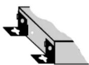
Secure attachment of mounting clips for panel - mounting
The compact and lightweight design of the Black Box Heavy-Duty LBHXXX allows it to be easily installed in almost any location. A Velcro strip may be used for
Black Box ^® Heavy Duty Edge Switches Installation and User Guide(07/05)
mounting the unit on a vertical surface such as a wall or cabinet, or for securing the unit on a table-top or shelf. Alternatively, metal mounting clips and screws are included for a rugged and secure mounting in any orientation.
Installation of the Black Box Heavy-Duty LBHXXX Edge Switches is a simple procedure. The installation location is dependent upon the physical layout of the Ethernet network and associated cabling. Make sure the unit is installed in a location that is easily accessible to an AC power outlet or the appropriate DC source and where cooling is not inhibited. The green Power (PWR) LED must turn ON when power is applied.
3.2 LH1505-RACK for Rack Mounting of Heavy-Duty LBH Switches
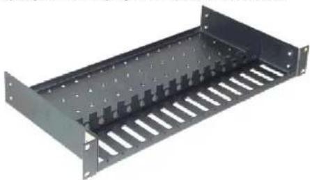
For 19" rack-mounting of Black Box Heavy-Duty LBHXXX Edge Switches, a rack-mount tray is available, the LH1505P-RACK. The Edge Switches are mounted with the DC power jack in the back, with the fiber and the RJ-45 connectors in the front. Any mix of the Edge
Black Box ^® Heavy Duty Edge Switches Installation and User Guide(07/05)
Switches and/or Media Edges may be placed on a tray, up to a maximum of 8 units. (The
mounting spaces of the
LH1505P-RACK are
specific to the Black Box
products and will not permit other models to be properly mounted).
natural_image
Metal rack-mounted device with slots and mounting holes (no text or symbols visible)In a typical installation, the
LH1505P-RACK, 19" rack-
mount tray will hold a few (three to eight) Heavy-Duty LBHXXX Edge Switches, with their power supplies plugged into power strips (not included) in the rear area of the tray.
Metal mounting screws in the bottom-front hold the Edge Switches firmly in place. The
Black Box ^® Heavy Duty Edge Switches Installation and User Guide(07/05)
beveled-top edge of the units permits the LEDs of each unit to be viewed for operational status, even when the units are very close together.
3.3 LH1505-RACK-1-9V and LH1505-RACK-2-9V for Rack Mounting Media Edges
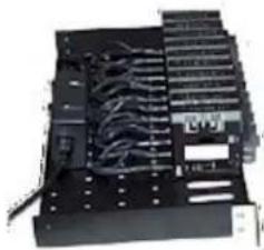
The LH1505-RACK-1-9V and LH1505-RACK-2-9V are other options for rack mounting the mix of Black Box 10Mbps and 100Mbps Edge Switches and Media Edges together in a 19" rack-mount tray. These models come with built-in common universal AC power supply rated at 55 watts at 50°C ambient,9VDC output, and supporting up to 2-3 Switches for LH1505-RACK-2-9V and 5 units Heavy-Duty LBHXXX for LH1505-RACK-1-9V. The LH1505-RACK-2-9V Model has two groups of Four units per power supply. The power supplies have auto-ranging AC input for use worldwide.
natural_image
Black electronic device with coiled and rectangular components (no visible text or symbols)Black Box ^3 Heavy Duty Edge Switches Installation and User Guide(07/05)
The side-view < here is an example of an installation of the model LH1505P-RACK, 19" rack-mount tray, holding a few LBHXXX, and LBH100A, each with their power input plugged into the built-in common AC power supply in the rear area of the tray. (AC PS units that come with the office models of the Edge Switch's are not used). Because of the
thicker size, only eight LBHXXX units can fit in or LII1505P-RACK.
Metal mounting screws in the bottom-front hold each of the Edge Switches, securing them in the tray and enabling separate removal for service. The dual LEDs permit viewing of Edge Switch status from any angle.
natural_image
Two electronic devices: a black rectangular device with copper contacts and a black rectangular device with a white label (no visible text or symbols on the device itself)3.4 DIN-Rail mounting option
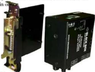
The Black Box LBHXXXH and
LBHXXXA(E)-P Edge Switches, designed for use in "Factory Floor" Industrial Ethernet environments, are available for DIN-Rail mounting in an enclosure having DIN Rails. A Black Box LBH240A-H is shown alongside the DIN-Rail-bracket here ->
Black Box ^® Heavy Duty Edge Switches Installation and User Guide(07/05)
The metal DIN-Rail mounting hardware is optional and needs to be ordered as a separate item. e.g. Model #XXXXX. It comes with four screws to attach the bracket to the MC unit. The rail clip is spring-loaded with a pull-up latch at the top for easy "snap-on" attachment and removal.
The Black Box LBHXXX models with "HD" and
"PD" have 24VDC power, and have the DIN-Rail-bracket included and assembled with the unit at the factory.
3.4 Power Requirements, Power Supply Types for Heavy-Duty LBHXXX Switches
Black Box Heavy-Duty LBHXXX Switches are power-efficient and can work with an external AC power supply. Black Box Heavy-Duty LBHXXX require a nominal 12VDC input version. LBH150A-
H or Extreme with 12VDC/ 24VDC/ -48VDC
natural_image
Close-up of a black network device with ports and connectors (no readable text or symbols)Black Box ^® Heavy Duty Edge Switches Installation and User Guide(07/05)
The extended temperature (H and P) versions are used for heavy duty industrial applications. The 12V DC power input jack has a plug of 2.5mm , center +ve, with 6 ft. cord. All the AC power supply info detail is provided in Technical Specs Section 1.1.
The Heavy-Duty LBHXXX are designed to be used with UL listed Class II power supplies. The LBHXXX Edge Switches provide reliable operation, withstand higher temperature environments, and provide the DC power choices to the user to deploy in uncontrolled temperature environments. The Direct DC (Internal) 12V DC (8 – 15V DC) has a built-in terminal block for +, -, ground. The 9V DC jack is also present. Detail information about the 12 VDC, the 24V DC and the -48V DC is provided in the Technical Specifications Section 1.1. The various models of DC power type and extended ambient temperature power supplies are numerous and your choice needs to be called out on your order.
Note: When connected to a -48 V centralized dc source these products are to be installed only in Restricted Access Areas (dedicated equipment rooms, electrical closets or the like).
Black Box ^® Heavy Duty Edge Switches Installation and User Guide(07/05)
3.5 Powering the LBHXXXA(E)-H and LBHXXXA(E)-P (DC internal) with 12V, 24V or -48VDC power input
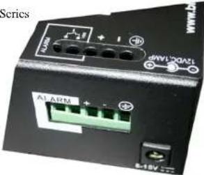
Each Black Box LBHXXXA(E)-H/LBHXXXA(E)-P Series
is equipped with an internal DC power supply,
and has built-in screw terminals for secure
attachment of the power input leads. Three DC
power models support a range of power input
types. The three DC power input terminal block
choices are for use with 12VDC, 24VDC or
48VDC power. Where an AC power adaptor is
used, DC is supplied via the jack. Power input from the DC
terminal block and the jack and both may be connected simultaneously for power input
redundancy.
Black Box ^3 Heavy Duty Edge Switches Installation and User Guide(07/05)
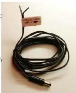
Note: The LBHXXXA(E)-II or P models with 24VDC support the Dual Source 24V input option. An external LH1505-CK (SHOWN AT RIGHT...and sold separately, or a customer-supplied equivalent) can be used to input 24VDC power to the LBHXXXA(E)-H or P unit via the jack. This is for 24VDC models only.
natural_image
Coiled black cable with a small metallic connector, no visible text or symbolsBlack Box ^3 Heavy Duty Edge Switches Installation and User Guide(07/05)
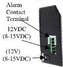
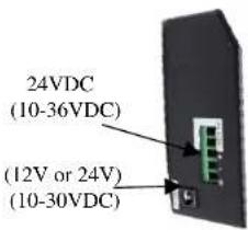
3.6 DC Power Terminals: "+", "-", gnd
GND: Terminal for "earth" or ground wire connection to the LBHXXXA(E)-H chassis
Input Voltage: 12VDC
24VDC
-48VDC
Input
current:
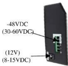
0.8 amp.(12V DC)
0.4 amp max.(24V DC)
0.2 amp max.(-48V DC)
Power Consumption: 7.0 watts typical, 9.0 watts max.
3.7 LBHXXXA(E)-H and P Series, DC-powered, 12VDC, 24VDC and -48VDC Installation
This section describes the proper connection of the -48VDC leads (or 24VDC, 12VDC leads) to the DC power terminal block on the Black Box LBHXXXA(E)-H Edge Switch (a shown in the Figure). The DC terminal block on the Black Box LBHXXXA(E)-H is located on the left
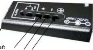
side of the unit and is equipped with three (3) screw-down lead posts. The power terminals are identified as positive (+) and negative (-), and they are floating inside the unit so that either of the terminals may be grounded by the user if desired. The chassis is "earth" or ground (GND). The connection procedure is straightforward. Simply insert the DC leads to
Black Box ^® Heavy Duty Edge Switches Installation and User Guide(07/05)
the LBIIXXXXA(E)-II's power terminals, positive (+) and negative (-) screws. The use of Ground (GND) optional; it connects to the Edge Switch chassis. Ensure that each lead is securely tightened from the top, as shown on above picture with arrow.
NOTE: Always use a voltmeter to measure the voltage of the incoming power supply and figure out the +ve potential lead or -ve potential lead. The more +ve potential lead will connect to the post labeled “+ve” and the rest to the “-ve”.
The GND can be hooked up at the last.
When power is applied, the green PWR LED will illuminate.
3.8 Connecting Ethernet Media
The Black Box LBHXXX-Series Edge Switches can be connected to two media types i.e. fiber and copper (RJ-45) types, runt at 100BASE-TX, 10BASE-T and 100BASE-FX only. CAT 5 cables should be used when making 100BASE-TX connections. When the ports are used as 10BASE-T ports, CAT 3 may be used. In either case, the maximum
Black Box ^® Heavy Duty Edge Switches Installation and User Guide(07/05)
distance for unshielded twisted pair cabling is 100 meters (328 ft). For fiber port 10BASE-FL or 100BASE-FX multi-mode, 50/125 or 62.5/125 microns cabling can be used, whereas for single-mode, 9/125 microns cabling should be used. Fiber cabling supports much longer cable distance and higher bandwidths as compared to copper wiring.
Media
Twisted Pair (CAT 3 or 5)
IEEE Standard
10BASE-T
Connector
RJ-45
Twisted Pair (CAT 5)
100BASE-TX
RJ-45
Fiber (Multi-mode)
100BASE-FX ST, SC
Fiber (Single-mode)
100BASE-FX SC, LC
Fiber (Multi-mode)
100BASE-FX MTRJ
NOTE: It is recommended that high quality CAT. 5 cables (which work for both 10 Mbps and 100Mbps) be used whenever possible in order to provide flexibility in a mixed-speed network, since LBIIXXX-series switch ports are auto-sensing for either 10 and 100Mbps. Note that the auto-cross function does not operate, if the port is fixed or not supporting auto-negotiation.
Black Box ^® Heavy Duty Edge Switches Installation and User Guide(07/05)
3.8.1 Connecting Twisted Pair
(RJ-45, CAT 3 or CAT 5, Unshielded or Shielded)
The following procedure describes how to connect a 10BASE-T or 100BASE-TX twisted pair segment to the RJ-45 port. The procedure is the same for both unshielded and shielded twisted pair cables.
- Using standard twisted pair media, insert either end of the cable with a RJ-45 plug into the RJ-45 connector of the port. Note that, even though the connector is shielded, either unshielded or shielded cables and wiring may be used.
- Connect the other end of the cable to the corresponding device.
- Use the LINK LED to ensure proper connectivity by noting that the LED will be illuminated when the unit is powered and proper connection is established. If this does not help, ensure that the cable is connected properly and that the device on the other end is powered and is not defective.
- All the RJ-45 ports are AUTO-Cross (MDIX), and will automatically determined the Link, while linking to another hub or Switch.
3.8.2 Connecting Fiber Optic ST-type, "twist-lock"
The following procedure applies to installations using ST-type fiber connectors. This procedure applies to ports using multi-mode ST fiber connectors.
Black Box ^® Heavy Duty Edge Switches Installation and User Guide(07/05)
- Before connecting the fiber optic cable, remove the protective dust caps from the tips of the fiber connectors. Save these dust caps for future use.
- Wipe clean the ends of the dual connectors with a soft cloth or lint-free lens tissue dampened in alcohol. Make certain the connectors are clean before connecting. Note: One strand of the duplex fiber optic cable is coded using color bands at regular intervals; you must use the color-coded strand on the associated ports at each end of the fiber optic segment.
- Connect the Transmit (TX) port (light colored post) on the Black Box Fiber port to the Receive (RX) port of the remote device. Begin with the color-coded strand of the cable for this first TX-to-RX connection.
- Connect the Receive (RX) port (dark colored post) to the Transmit (TX) port of the remote device. Use the non-color coded fiber strand for this.
- The LINK LED on the front of the fiber connector will illuminate when a proper connection has been established at both ends (and when power is ON in the unit). If LINK is not lit after cable connection, the normal cause is improper cable polarity. Swap the fiber cables at the fiber connector to remedy this situation.
3.8.3 Connecting Fiber Optic SC-type , "Snap-In"
The following procedure applies to installations using SC-type fiber connectors, i.e., using multi-mode SC and SC single-mode. While connecting
Black Box ^® Heavy Duty Edge Switches Installation and User Guide(07/05)
fiber media to SC connectors, simply snap on the two square male connectors into the SC female jacks of the Fiber connector until it clicks and secures.
3.8.4 Connecting Single-MoHiber Optic
When using single-mode fiber cable, be sure to use single-mode fiber port connectors. Single-mode fiber cable has a smaller diameter than multi-mode fiber cable (9/125 microns for single-mode, 50/125 or 62.5/125 microns for multi-mode where xx/xx are the diameters of the core and the core plus the cladding respectively). Single-mode fiber allows full bandwidth at longer distances, about 20Km with the multi-mode SC.
The same procedures as for multi-mode fiber apply to single-mode fiber connectors. Follow the steps listed in Section 3.8.2 above.
Black Box ^® Heavy Duty Edge Switches Installation and User Guide(07/05)
3.8.5 Power Budget Calculations
for Heavy-Duty LBHXXX, Fiber Media
Receiver Sensitivity and Transmitter Power are the parameters necessary to compute the power budget. To calculate the power budget of different fiber media installations using Black Box products, the following equations should be used:
OPB (Optical Power Budget) = P_1 (min) - P_R (min)
where P_T = Transmitter Output Power, and P_R = Receiver Sensitivity
Worst case OPB = OPB - 1dB(for LED aging) - 1dB(for insertion loss)
Worst case distance = {Worst case OPB, in dB} / [Cable Loss, in dB/Km] where the "Cable Loss" for 62.5/125 and 50/125μm (m.m.) is 2.8 dB/km, and the "Cable Loss" for 100/140 (Multi-mode) is 3.3 dB/km,
and the "Cable Loss" for 9/125 (Single-mode) is 0.5 dB/km and the "Cable Loss" for 9/125 (Single-mode) is 0.25 dB/km (SSCX)
The following data has been collected from component manufacturer's (Agilent's, JDS-Uniphase, stratus, Lucents') web sites and catalogs to provide guidance to network integrators and installers-
Black Box ^® Heavy Duty Edge Switches Installation and User Guide(07/05)
| Fiber Port Module | Speed, Std. | Mode | Std. km fdx (hdx) | Wavelength nm | Cable Size μm | X'mitr Output P_T , dB | R'cvr Sens. P_R ,dB | Worst OPB, dB | Worst* distance Km, fdx | typical OPB, dB | typical* distance Km, fdx |
| LBHXXX-MST, MSC | 100Mb FX | Multi-mode | 2(0.4) | 1310 | 62.5/12550/125 | -20-23.5 | -31-31 | 9.05.5 | 2.52.0 | 1412 | 54 |
| LBHXXX-SSC | 100Mb FX | Single-mode | 20(0.4) | 1310 | 9/125 | -15 | -31 | 14 | 28 | 17.5 | |
| LBHXXX-MTRJ | 100Mb FX | Multi-mode | 2(0.4) | 1310 | 62.5/12550/125 | -20-23.5 | -31-31 | 9.05.5 | 3.02.0 | 15.812.2 | 5.54.0 |
| Long Reach | 100Mb FX | Single-mode | 40(0.4) | 1310 | 9/125 | -5 | -34 | 27 | 54 | 32.5 | |
| LBHXXX-LC | 100Mb FX | Single-mode | 15+ | 1310 | 9/125 | -15 | -28 | 11 | 22 | - | - |
| LBHXXX-SSCX | 100Mb FX | Single-mode | 100 | 1550 | 9/125 | -5 | -35 | 28 | 112 | - | |
| LBHXXX-SFC | 100Mb FX | Single-mode | 20(0.4) | 1310 | 9/125 | -16 | -32 | 14 | 28 | - | - |
Black Box ^® Heavy Duty Edge Switches Installation and User Guide(07/05)
* Note: The use of either multi-mode or single-mode fiber to operate at 100Mbps speed over long distances (i.e., over approx. 400 meters) can be achieved only if the following factors are both applied:
- The 100Mb fiber segment must operate in full-duplex (FDX) mode, and
- The worst-case OPB of the fiber link must be greater than the fiber cable's passive Attenuation.
(Attenuation = Cable loss + LED aging loss + Insertion loss + safety factor)
3.8.6 Connections to NICs
which support Auto-Negotiation, RJ-45 ports
The copper ports of Black Box LBH1XXX-Series Edge Switches will function properly with NICs (Network Interface Cards) which support Auto-Negotiation, and the Fast Link Pulse (FLP) coding for the 100BASE-TX signaling system. When connecting a NIC to the LBH1XXX-Series, it may be necessary to reload the NIC drivers on the user device if the NIC has been communicating with a protocol other than 100BASE-TX (such as 10BASE-T). When 100Mb operation is agreed and in use, the 10/100 LED is illuminated steady ON and is OFF, if 10 Mbps traffic.
4.0 OPERATION
4.1 Dual-Speed Functionality, and Switching
The Black Box Heavy-Duty LBHXXX Edge Switches provide SIX switched ports with combination of fiber and copper or copper only. The architecture supports a dual speed switching environment, with standard auto-negotiation capability.
The switched RJ-45 ports are full- or half-duplex auto-sensing for mode and speed, and auto-cross for plug polarity. (See Section 4.2). When the connected device is 10 Mbps, the LBHXXXs obeys all the rules of 10 Mbps Ethernet configurations. The 10 Mbps users can “communicate” with 100Mbps users as well as other 10 Mbps users through the switch. Similarly, the 100Mbps traffic obeys the rules of 100Mbps Ethernet, and can communicate with 10 Mb and 100Mb uscrs. Black Box Heavy-Duty LBHXXX units are plug-and-play devices. There is no software configuring to be done at installation or for maintenance, even for the LLL ports. The internal functions of both are described below.
Black Box ^® Heavy Duty Edge Switches Installation and User Guide(07/05)
Switching, Filtering and Forwarding
Each time a packet arrives on one of the switched ports, the decision is taken to either filter or to forward the packet. Packets whose source and destination addresses lie on the same port segment will be filtered, constraining them to one port and relieving the rest of the network from processing them. A packet whose destination address is on another port segment will be forwarded to the appropriate port, and will not be sent to the other ports where it is not needed. Packets needed for maintaining the operation of the network (such as occasional multi-cast packets) are forwarded to all ports. The Black Box Heavy-Duty LBHXXX Edge Switches operate in the store-and-forward switching mode, which eliminates bad packets and enables peak performance to be achieved when there is heavy traffic on the network.
Switching, Address Learning
The Black Box Heavy-Duty LBHXXX units have address table capacity of 2K node addresses, and are suitable for use in large networks. They are self-learning, so that as nodes are added or removed or moved from one segment to another, the LBHXXX- Series switch automatically keeps up with node locations.
An address-aging algorithm causes least-used addresses to fall out in favor of new frequently-used addresses. To reset the address buffer, cycle power down-and-up.
Black Box ^® Heavy Duty Edge Switches Installation and User Guide(07/05)
4.2 Auto-cross (MDIX),
Auto-negotiation and Speed-sensing
The RJ-45 ports independently support auto-cross (MDI or MDIX) in auto-negotiation mode and will work properly with all the other connected devices with RJ-45 port whether it supports Auto-negotiation or not (e.g 10Mb Hub) or fixed mode at 10Mb or 100Mb Half/Full Duplex(managed switch). No cross-over cable is required while using the LBHXXX's Auto-negotiation port to other devices. Operation is according to the IEEE 802.3u standard.
When a RJ-45 cable connection is made, and each time a LINK is enabled, auto-negotiation takes place. The Black Box Heavy-Duty LBHXXX advertises its capability for 10 or 100 Mbps speed and F/H duplex mode, and the device at the other end of the cable should similarly advertise / respond and both sides will agree to the speed and mode being used. Depending upon the device connected, this will result in agreement to operate at either 10 Mbps or 100Mbps speed, full- or half-duplex mode. Even a managed switch will connect at fixed mode (100Mb Full Duplex), the LBHXXX will connect at 100Mb Half duplex only. Since the Auto-negotiating LBHXXX will advertise the speed only and not look for the duplex mode set on the other side.
Black Box ^® Heavy Duty Edge Switches Installation and User Guide(07/05)
4.3 Dual LEDs, Front-panel and side-panel (Black Box Heavy-Duty LBHXXX)
LED Description
PWR Illuminates GREEN to indicate power applied.
LK/ ACT Steady ON for LINK w/no traffic, blinking for activity per port. LINK will turn off in the event connectivity is lost between the ends of the twisted pair segment or a loss of power occurs in the unit or remote device. The Link ports are also represented by LA1, LA2, LA3...LA6. (Steady On or steady Off indicates no Receive Activity).
10/100 Steady ON for 100Mb speed, OFF for 10Mb speed per port (copper ports) F/H (FH1, FH2) Steady ON for Full duplex (F/D) mode, OFF for Half duplex (H/D) mode per port (For fiber port only)
NOTE: The port#1 and 2 is being assigned for copper or fiber port for different models. On all copper 10/100 ports model (c.g LBHXXXA), the LEDs 10 or 100 denotes for copper port only. For the model 4copper +2 fiber or 5copper +1fiber.(e.g LBHXXXA(E)-H-xx-yy) the xx denotes for fiber port only.
4.4 Hardware operated Alarm Contact
for monitoring internal power supply
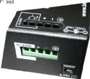
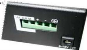
The two screws Alarm Contacts feature, standard on Black Box LBHXXXA(E)-H and P, provides Normally Closed (NC) contacts to which the user can attach one sets of status monitoring wires at the green terminal block. When this option is present, the terminal block for Alarm Contacts is part of the Power Input panel in the Black Box LBHXXXs case. The DC power input connection is in the same panel.
The NC Alarm Contact is held close when there is power on the
main board inside of the LBHXXX. This provides a "Hardware operated Alarm" because the NC contacts will open when internal power is lost, either from an external power down condition or by the failure of the power supply inside of the Black Box LBHXXX Switch.
natural_image
Close-up of a black electronic device with green connectors and a small terminal labeled 'B-12V', no readable text or symbols beyond labels.Black Box ^® Heavy Duty Edge Switches Installation and User Guide(07/05)
Useful info about Alarm Contacts in LBHXXXA(E)-II and LBHXXXA(E)-P:
- Two-position terminal block (1,2) provided next to the DC power input, as shown above.
- The Alarm Relay contact connected to the two terminals (1,2) is hardware operated.
- By default it is NC (normally closed). It will open if there is any loss of power to the electronics inside of the unit.
5.0 TROUBLESHOOTING
All BLACKBOX products are designed to provide reliability and consistently high performance in all network environments. The installation of LBH1xxA Series 10/100 Mb/s Switches is a straightforward procedure (see INSTALLATION, Section 3.0); the operation is also straightforward and is discussed in Section 4.
Should problems develop during installation or operation, this section is intended to help locate, identify and correct these types of problems. Please follow the suggestions listed below prior to contacting your supplier. However, if you are unsure of the
Black Box ^® Heavy Duty Edge Switches Installation and User Guide(07/05)
procedures described in this section or if the LBIIXXX Series 10/100 Mb/s Switch is not performing as expected, do not attempt to repair the unit; instead contact your supplier for assistance or contact BLACK BOX Customer Support.
5.1 Before Calling for Assistance
- If difficulty is encountered when installing or operating the unit, refer back to the Installation Section of the applicable chapter of this manual. Also check to make sure that the various components of the network are intecropcrable.
- Check the cables and connectors to ensure that they have been properly connected and the cables/wires have not been crimped or in some way impaired during installation. (About 90% of network downtime can be attributed to wiring and connector problems.)
- Make sure that an AC power cord is properly attached to each LBI1101A Series unit. Be certain that the AC power cord is plugged into a functioning electrical outlet. Use the PWR LEDs to verify each unit is receiving power.
Black Box ^® Heavy Duty Edge Switches Installation and User Guide(07/05)
-
If the problem is isolated to a network device other than the LBHXXX and LBHXXX Series 10/100 Mb/s switch product, it is recommended that the problem device is replaced with a known good device. Verify whether or not the problem is corrected. If not, go to Step 5 below. If the problem is corrected, the LBHXXX Scrics Switch and its associated cables are functioning properly.
-
If the problem continues after completing Step 4 above, contact your supplier of the LBIIXXX Scrics 10/100 Mb/s Switch unit or if unknown, contact BLACK BOX, Inc by phone at (724) 746-5500 or by other appropriate method
5.2 When Calling for Assistance
Please be prepared to provide the following information.
- A complete description of the problem, including the following points:
a. The nature and duration of the problem;
b. Situations when the problem occurs:
c. The components involved in the problem;
d. Any particular application that, when used, appears to create the problem;
Black Box ^® Heavy Duty Edge Switches Installation and User Guide(07/05)
- An accurate list of BLACK BOX product model(s) involved, with serial number(s). Include the date(s) that you purchased the products from BLACK BOX.
- It is useful to include other network equipment models and related hardware, including Convenient computers, workstations, terminals and printers; plus, the various network media types being used.
- A record of changes that have been made to your network configuration prior to the occurrence of the problem. Any changes to system administration procedures should all be noted in this record.
Black Box ^® Heavy Duty Edge Switches Installation and User Guide(07/05)
5.3 Return Material Authorization (RMA) Procedure
Shipping and Packaging Information
Should you need to ship the unit back to Black Box Corporation, please follow these instructions:
- Package the unit carefully. It is recommended that you use the original container if available. Units should be wrapped in a "bubble-wrap" plastic sheet or bag for shipping protection. (You may retain all connectors and this Installation Guide.)
CAUTION : Do not pack the unit in Styrofoam "popcorn" type packing material. This material may cause electro-static shock damage to the unit.
-
Clearly mark the Return Material Authorization (RMA) number on the outside of the shipping container.
-
Black Box Corporation is not responsible for your return shipping charges.
-
Ship the package to:
Black Box Corporation
1000
Park
Drive
Lawrence,
PA
15055
Phone:
(724)
746-5500
Fax:
(724)
746-0746
- BLACK BOX
- NETWORK SERVICES
- Heavy Duty Edge Switches
- BLACK BOX ® Series
- Installation and User Guide
- Trademarks
- Black Box Heavy Duty Edge Switches Installation and User Guide (07/05)
- FEDERAL COMMUNICATIONS COMMISSION AND
- CANADIAN DEPARTMENT OF COMMUNICATIONS RADIO FREQUENCY INTERFERENCE STATEMENTS
- CAUTION:
- TABLE OF CONTENTS
- Revisions
- Black Box ® Heavy Duty Edge Switches Installation and User Guide(07/05)
- SPECIFICATIONS (Heavy-Duty Edge Switches)
- Technical Specifications
- Ports Performance
- Network Standards
- Packet-Processing Between Domains
- Operating Environment
- Storage Temperature.
- Cold Start:
- Packaging:
- Cooling Method:
- POWER SUPPLY
- Direct DC POWER SUPPLY : built-in terminal
- Office Models Ratings (0 to 40°C)
- Factory Floor Models (H) Ratings (-25 to 60°C)
- Temperature un-controlled Extreme (P) Ratings (-40 to 75°C)
- Port Connectors:
- LED Indicators (Front)
- Mounting options
- Agency Approvals and Standards Compliance:
- Summary of models and descriptions
- Accessories
- INTRODUCTION
- Inspecting the Package and the Product
- Product Description
- Black Box 3 Heavy Duty Edge Switches Installation and User Guide(07/05)
- Frame Buffering and Latency
- Features and Benefits
- Applications for Heavy-Duty LBHXXX Edge Switches
- Example 2: LBHXXXA(E)-H and LBH100AE
- INSTALLATION
- Locating the Edge Switch Unit
- LH1505-RACK for Rack Mounting of Heavy-Duty LBH Switches
- LH1505-RACK-1-9V and LH1505-RACK-2-9V for Rack Mounting Media Edges
- DIN-Rail mounting option
- Power Requirements, Power Supply Types for Heavy-Duty LBHXXX Switches
- LBHXXXA(E)-H and P Series, DC-powered, 12VDC, 24VDC and -48VDC Installation
- Connecting Ethernet Media
- Media
- IEEE Standard
- Connector
- Connecting Twisted Pair
- (RJ-45, CAT 3 or CAT 5, Unshielded or Shielded)
- Connecting Fiber Optic ST-type, "twist-lock"
- Connecting Fiber Optic SC-type , "Snap-In"
- Connecting Single-MoHiber Optic
- Power Budget Calculations
- for Heavy-Duty LBHXXX, Fiber Media
- Connections to NICs
- which support Auto-Negotiation, RJ-45 ports
- OPERATION
- Dual-Speed Functionality, and Switching
- Switching, Filtering and Forwarding
- Switching, Address Learning
- Auto-cross (MDIX),
- Auto-negotiation and Speed-sensing
- Dual LEDs, Front-panel and side-panel (Black Box Heavy-Duty LBHXXX)
- LED Description
- Hardware operated Alarm Contact
- TROUBLESHOOTING
- Before Calling for Assistance
- When Calling for Assistance
- Return Material Authorization (RMA) Procedure
- Shipping and Packaging Information
Brand : Black Box
Model : LBH600A-P-12
Category : Network switch