ACXC48-SHIP - Network switch Black Box - Free user manual and instructions
Find the device manual for free ACXC48-SHIP Black Box in PDF.

User questions about ACXC48-SHIP Black Box
0 question about this device. Answer the ones you know or ask your own.
Ask a new question about this device
Download the instructions for your Network switch in PDF format for free! Find your manual ACXC48-SHIP - Black Box and take your electronic device back in hand. On this page are published all the documents necessary for the use of your device. ACXC48-SHIP by Black Box.
USER MANUAL ACXC48-SHIP Black Box
DKM FXC SWITCH SERIES
COMPACT KVM MATRIX SWITCHES
24/7 TECHNICAL SUPPORT AT 1.877.877.2269 OR VISIT BLACKBOX.COM
natural_image
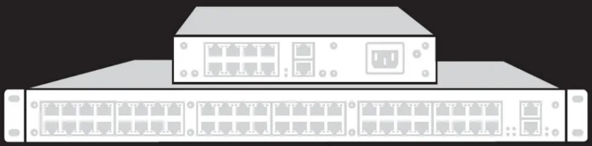
Illustration of a server rack with two Ethernet ports and a top-mounted unit (no text or symbols)TABLE OF CONTENTS
SAFETY INSTRUCTIONS....6
Installation 6
Repair....6
1. SPECIFICATIONS....7
1.1 Interfaces 7
1.1.1 RJ-45 (Network)....7
1.1.2 RJ-45 (Serial) 7
1.1.3 RJ-45 (Interconnect) 7
1.2 Interconnect Cable....7
CATx 7
1.3 Connector Pinouts 8
I/O Port CATx 8
1.4 Power Supply 9
1.5 Environmental Conditions ...... 9
1.6 Dimensions .... 10
1.7 Shipping Weight....11
1.8 MTBF 12
- OVERVIEW....13
2.1 Application....13
2.2 Access Options 13
2.3 System Overview....14
2.4 Product Range....15
2.5 Options....15
2.6 Device Views....16
2.6.1 80-Port Chassis Models (ACXC80, ACXC80F, ACXC80FHS, ACXC48F32)....16
2.6.2 64-Port Chassis Models (ACXC64, ACXC64F, ACXC64FHS, ACXC48F16)....18
2.6.3 48-Port Chassis Models (ACXC48, ACXC48F, ACXC48FHS, ACXC48U)....20
2.6.4 32-Port Chassis Models (ACXC32, ACXC32F, ACXC32FHS, ACXC32U)....21
2.6.5 16-Port Chassis Models (ACXC16, ACXC16F, ACXC16FHS, ACXC16U) 22
2.6.6 8-Port Chassis Models (ACXC8, ACXC8F, ACXC8FHS, ACXC8U) 23
2.6.7 8-Port Board Models (ACXC8-M, ACXC8F-M)....23
2.7 Diagnostics and Status....24
2.7.1 Status LEDs....24
2.7.2 Port Status 28
2.7.3 Port Status Matrix Grid 32
2.7.4 Extender OSD 33
2.7.5 Network Status 35
2.7.6 Firmware Status Matrix....37
2.7.7 Firmware Status Extender 39
2.8 Trace Function....40
2.9 Syslog Monitoring 41
2.10 SNMP 43
TABLE OF CONTENTS
2.11 System Check 47
2.12 Device Finder 48
- INSTALLATION .... 50
3.1 Package Contents ....50
3.2 System Setup ....50
3.3 Example Applications....51
3.3.1 KVM Matrix....52
3.3.2 Parallel Operation (Stacking) 53
3.3.3 Matrix Grid 54
- CONFIGURATION 55
4.1 Command Mode....55
4.2 Control Options 57
4.2.1 Control via OSD....57
4.2.2 Control via Java Tool 61
4.2.3 Control via Serial Interface....67
4.3 Assignment....68
4.3.1 Virtual CPU 68
4.3.2 Virtual Console 70
4.4 System Settings....72
4.4.1 System Data 72
4.4.2 Automatic ID 75
4.4.3 Access....78
4.4.4 Switch....80
4.4.5 Network....84
4.4.6 Date and Time....88
4.5 User Settings 91
4.5.1 User 91
4.5.2 Favorite List Users 94
4.5.3 User Macros....96
4.6 Extender Settings....100
Flexible Port Extender Units 102
4.7 USB 2.0 Extender....103
4.8 Extenders for I/O Boards (USB 2.0/USB 3.0)....105
4.9 Configuration of SDI....108
4.10 CPU Settings....110
4.11 Console Settings 113
4.11.1 CON Devices 113
4.11.2 Mouse and Keyboard....118
4.11.3 Extender OSD 121
4.11.4 Favorite List Consoles 123
4.11.5 Console Macros 126
4.11.6 Shared Operation....129
4.11.7 Multi-Screen Control 131
TABLE OF CONTENTS
4.12 Saving and Loading Configurations....134
4.12.1 Active Configuration 134
4.12.2 Saving Configurations (Internal) 134
4.12.3 Loading Configurations (Internal)....136
4.12.4 Saving Configurations (External)....137
4.12.5 Loading Configurations (External)....138
4.13 Export and Import Options....139
4.13.1 Export Options 139
4.13.2 Import Options....140
4.14 Matrix Cascading....141
4.15 Matrix Grid....143
4.16 Firmware Update 147
4.16.1 Matrix Update 147
4.16.2 Extender Update....149
4.17 License Management....152
5. OPERATION.... 153
5.1 Operation via Hotkeys....153
5.1.1 Direct Switching....153
5.1.2 Scan Mode 154
5.1.3 Function Keys:
5.1.4 Addressing of Main and Sub Matrices 155
5.2 KVM Switching....156
5.3 Exended Switching....158
5.4 Switching of Single Extenders within Devices 163
5.5 CON Switch....164
5.6 Multi-Screen Control....165
5.7 USB 2.0 Switching....166
5.8 Presets 166
5.9 Serial Interface 168
5.10 Power On and Power Down Functions ....168
5.10.1 Restart 168
5.10.2 Factory Reset 169
5.10.3 Power Down 169
5.11 Summary of Keyboard Commands....170
6. MAINTENANCE 172
7. TROUBLESHOOTING....173
7.1 External Failure 173
7.2 Video Interference....173
7.3 Malfunction of Fans ....173
7.4 Malfunction of Power Supply Units 173
TABLE OF CONTENTS
NEED HELP?
LE AVE THE TECH TO US
LIVE 24/7
TECHNICAL
SUPPORT
1.8 7 7.87 7.2269
7.5 Network Error....173
7.6 Failure at the Matrix....174
7.7 Blank Screen 174
-
TECHNICAL SUPPORT....175
8.1 Support Checklist....175
8.2 Shipping Checklist 175 -
REGULATORY INFORMATION 176
9.1 FCC Statement....176
9.2 CE Declaration of Conformity 176
9.3 Product Safety....176
9.4 WEEE 176
9.5 RoHS/RoHS2 176
- GLOSSARY 177
10.1 Video and KVM Technology Terms....177
10.2 Matrix-Specific Terms....178
- DISCLAIMER/TRADEMARKS 180
11.1 Disclaimer....180
11.2 Trademarks Used in this Manual....180
SAFETY INSTRUCTIONS
To ensure reliable and safe long-term operation of your Compact KVM Matrix Switch, note the following guidelines.
INSTALLATION
Only use the device according to this User Manual. Failure to follow these procedures could result in damage to the equipment or injury to the user or installer.
- Only use in dry, indoor environments.
The Compact KVM Matrix Switch and the power supply units can get warm. Do not install components in an enclosed space without any airflow.
- Do not obscure ventilation holes.
Only use power supplies originally supplied with the product or manufacturer-approved replacements. Do not use a power supply if it appears to be defective or has a damaged chassis.
Connect all power supplies to grounded outlets. In each case, ensure that the ground connection is maintained from the outlet socket through to the power supply's AC power input.
In case the device is equipped with one or more grounding screws, be sure to use these for normal operation to ensure the grounding of the chassis.
- Do not connect the link interface to any other equipment, particularly network or telecommunications equipment.
Only connect devices to the serial interface that are protected against short circuit currents and incorrect voltages at the serial interface.
To disconnect the Compact KVM Matrix Switch from the power supply, remove the power cord cables of all power supply units or switch supplies off.
Take any required ESD precautions.
- To disconnect the device completely from the electric circuit, all power cables have to be removed.
REPAIR
- Do not attempt to open or repair a power supply unit.
- Do not attempt to open or repair the Compact KVM Matrix Switch. There are no user serviceable parts inside.
- Contact Black Box Technical Support at 877-877-2269 or info@blackbox.com if there is a fault.
1.1 INTERFACES
1.1.1 RJ-45 (NETWORK)
The communication of the CATx devices requires a 1000BASE-T connection.
The cabling must comply with EIA/TIA-568-B (1000BASE-T) standards with RJ45 connectors at both ends. All four wire pairs are used in both directions. The cabling is suitable for a full duplex operation. For the cable connection to a source (computer, CPU), you must use a crossed network cable (cross cable).
1.1.2 RJ-45 (SERIAL)
Communication takes place with a transmission speed of 115.2 KBaud, regardless of the file format. The transmission takes place with eight data bits and a stop bit, but without a parity bit. Limited hardware handshake (DSR) is possible.
1.1.3 RJ-45 (INTERCONNECT)
Communication between CATx devices requires a 1000BASE-T connection.
Connector wiring must comply with EIA/TIA-568-B (1000BASE-T), with RJ-45 connectors at both ends. All four cable wire pairs are used.
1.2 INTERCONNECT CABLE
CATX
NOTE: A point-to-point connection is required. Operation with several patch fields is possible. Routing over an active network component, such as an Ethernet Hub, Router or Matrix, is not allowed.
- Avoid routing CATx cables along power cables.
CAUTION: To maintain regulatory EMC compliance, correctly installed shielded CATx cable must be used throughout the interconnection link.
CAUTION: To maintain regulatory EMC compliance, all CATx cables need to carry ferrites on both cable ends close to the device.
TYPE OF INTERCONNECT CABLE
The Compact KVM Matrix Switch requires interconnect cabling specified for Gigabit Ethernet (1000BASE-T). The use of solid-core (AWG24), shielded, CAT5e (or better) is recommended.
TABLE 1-1. INTERCONNECT CABLE TYPES
| CABLE TYPE DESCRIPTION | |
| CATx Solid-Core Cable AWG24 | Cable S/UTP (CAT5e) cable according to EIA/TIA- 568-B. Four pairs of AWG24 wires.Connection according to EIA/TIA-568-B (1000BASE-T). |
| CATx Patch Cable AWG26/8 | Cable S/UTP (CAT5e) cable according to EIA/TIA- 568-B. Four pairs of AWG26/8 wires.Connection according to EIA/TIA-568-B (1000BASE-T). |
CHAPTER 1: SPECIFICATIONS
NEED HELP?
LE AVE THE TECH TO US
LIVE 24/7
TECHNICAL
SUPPORT
1.8 7 7.87 7.2269
NOTE: The use of flexible cables (patch cables) type AWG26/8 is possible, but the maximum possible extension distance is halved.
TABLE 1-2. MAXIMUM ACCEPTABLE CABLE LENGTHS
| CABLE TYPE LENGTH |
| CATx Solid-Core Cable AWG24 400 ft. (140 m) |
| CATx Patch Cable AWG26/8 200 ft. (70 m) |
1.3 CONNECTOR PINOUTS
TABLE 1-3. RJ-45 (SERIAL)
| PICTURE PIN SIGNAL PIN SIGNAL | ||||
 | 1 | DCD | 5 | RxD |
| 2 | DSR | 6 | TxD | |
| 3 | RTS | 7 | CTS | |
| 4 | GND | 8 | DTR | |
TABLE 1-4. RJ-45 (SERIAL)
| PICTURE PIN SIGNAL | PIN SIGNAL | |||
 | 1 | D1+ | 5 | Not connected |
| 2 | D1- | 6 | D2- | |
| 3 | D2+ | 7 | Not connected | |
| 4 | Not connected | 8 | Not connected | |
I/O PORT CATX
TABLE 1-5. RJ-45
| PICTURE PIN SIGNAL | PIN SIGNAL | |||
 | 1 | D1+ | 5 | D3- |
| 2 | D1- | 6 | D2- | |
| 3 | D2+ | 7 | D4+ | |
| 4 | D3+ | 8 | D4- | |
1.4 POWER SUPPLY
TABLE 1-6. MAXIMUM CURRENT/VOLTAGE
| PRODUCT CODE MAX. CURRENT/VOLTAGE | |
| ACXC8, ACXC8U, ACXC8-M, ACXC8F-M, ACXC8F, ACXC8FHS 0.7 A, 100-240 VAC, 50/60 Hz | |
| ACXC48, ACXC48F, ACXC48FHS, ACXC48U, ACXC32, ACXC32F, ACXC32FHS, ACXC32U, ACXC16, ACXC16F, ACXC16FHS, ACXC16U | 1.4 A, 100-240 VAC, 50/60 Hz |
| ACXC80, ACXC80F, ACXC80FHS, ACXC48F32, ACXC64, ACXC64F, ACXC64FHS, ACXC48F16 | 12.3 A, 100-240 Vac, 50/60 Hz |
TABLE 1-7. POWER REQUIREMENT
| PRODUCT CODE MAX. CURRENT/VOLTAGE | |
| ACXC80, ACXC80F, ACXC80FHS 125 W max. | |
| ACXC48F32 125 W max. | |
| ACXC64, ACXC64F, ACXC64FHS 105 W max. | |
| ACXC48F16 105 W max. | |
| ACXC48, ACXC48F, ACXC48FHS, ACXC48U | 90 W max. |
| ACXC32, ACXC32F, ACXC32FHS, ACXC32U | 65 W max. |
| ACXC16, ACXC16F, ACXC16FHS, ACXC16U | 40 W max. |
| ACXC8U, ACXC8F, ACXC8FHS, ACXC8U | 13 W max. |
| ACXC8-M, ACXC8F-M | 13 W max. |
1.5 ENVIRONMENTAL CONDITIONS
TABLE 1-8. TEMPERATURE AND HUMIDITY
| SPECIFICATION | VALUE |
| Operating Temperature | 41 to 113°F (5 to 45°C) |
| Storage Temperature | -13 to 140°F (-25 to 60°C) |
| Relative Humidity | Max. 80% non-condensing |
TABLE 1-9. NOISE EMISSION
| SPECIFICATION | VALUE |
| Sound Pressure Level (SPL) | 64/80-port chassis: max. 52 dBA per fan;16/32/48-port chassis: max. 42 dBA per fan |
TABLE 1-10. HEAT DISSIPATION
| SPECIFICATION | VALUE |
| Thermal Output | Corresponds to power consumption in Watt (W) |
1.6 DIMENSIONS
TABLE 1-11. DIMENSIONS
| PRODUCT CODE SPECIFICATION DIMENSION | |
| ACXC80, ACXC80F, ACXC80FHS | Matrix 3.5"H x 17.4"W x 17.1"D (9 x 44.3 x 43.5 cm) |
| Shipping Box 7.9"H x 23.7"W x 20.7"D (20 x 60.2 x 52.6 cm) | |
| ACXC48F32 | Matrix 3.5"H x 17.4"W x 17.1"D (9 x 44.3 x 43.5 cm) |
| Shipping Box 7.9"H x 23.7"W x 20.7"D (20 x 60.2 x 52.6 cm) | |
| ACXC64, ACXC64F, ACXC64FHS | Matrix 3.5"H x 17.4"W x 17.1"D (9 x 44.3 x 43.5 cm) |
| Shipping Box 7.9"H x 23.7"W x 20.7"D (20 x 60.2 x 52.6 cm) | |
| ACXC48F16 | Matrix 3.5"H x 17.4"W x 17.1"D (9 x 44.3 x 43.5 cm) |
| Shipping Box 7.9"H x 23.7"W x 20.7"D (20 x 60.2 x 52.6 cm) | |
| ACXC48, ACXC48F, ACXC48FHS, ACXC48U | Matrix 1.8"H x 17.4"W x 17.1"D (4.5 x 44.3 x 43.5 cm) |
| Shipping Box 6.1"H x 23.7"W x 20.7"D (15.4 x 60.2 x 52.6 cm) | |
| ACXC32, ACXC32F, ACXC32FHS, ACXC32U | Matrix 1.8"H x 17.4"W x 17.1"D (4.5 x 44.3 x 43.5 cm) |
| Shipping Box 6.1"H x 23.7"W x 20.7"D (15.4 x 60.2 x 52.6 cm) | |
| ACXC16, ACXC16F, ACXC16FHS, ACXC16U | Matrix 1.8"H x 17.4"W x 17.1"D (4.5 x 44.3 x 43.5 cm) |
| Shipping Box 6.1"H x 23.7"W x 20.7"D (15.4 x 60.2 x 52.6 cm) | |
| ACXC8, ACXC8F, ACXC8FHS, ACXC8U | Matrix 1.8"H x 8.7"W x 5.7"D (4.5 x 22 x 14.6 cm) |
| Shipping Box 4.5"H x 21.7"W x 14.4"D (11.5 x 55 x 36.5 cm) | |
| ACXC8-M, ACXC8F-M | Matrix 1.6"H x 3.9"W x 5.5"D (4.3 x 10 x 14 cm) |
| Shipping Box 1.8"H x 8.7"W x 5.7"D (4.5 x 22 x 14.6 cm) | |
1.7 SHIPPING WEIGHT
TABLE 1-12. SHIPPING WEIGHT
| PRODUCT CODE SPECIFICATION DIMENSION | |
| ACXC80, ACXC80F, ACXC80U | Matrix 15.9 lb. (7.2 kg) |
| Shipping Box 21.1 lb. (9.6 kg) | |
| ACXC48F32 | Matrix 15.9 lb. (7.2 kg) |
| Shipping Box 21.1 lb. (9.6 kg) | |
| ACXC64, ACXC64F, ACXC64FHS | Matrix 15.4 lb. (7.0 kg) |
| Shipping Box 20.7 lb. (9.4 kg) | |
| ACXC48F16 | Matrix 15.4 lb. (7.0 kg) |
| Shipping Box 20.7 lb. (9.4 kg) | |
| ACXC48, ACXC48F, ACXC48FHS, ACXC48U | Matrix 9.0 lb. (4.1 kg) |
| Shipping Box 13.2 lb. (6.0 kg) | |
| ACXC32, ACXC32F, ACXC32FHS, ACXC32U | Matrix 8.8 lb. (4.0 kg) |
| Shipping Box 13.0 lb. (5.9 kg) | |
| ACXC16, ACXC16F, ACXC16FHS, ACXC16U | Matrix 8.6 lb. (3.9 kg) |
| Shipping Box 12.8 lb. (5.8 kg) | |
| ACXC8, ACXC8F, ACXC8FHS, ACXC8U | Matrix 1.9 lb. (0.9 kg) |
| Shipping Box 7.5 lb. (3.4 kg) | |
| ACXC8-M, ACXC8F-M | Matrix 2 lb. (0.9 kg) |
| Shipping Box 4 lb. (1.8 kg) | |
CHAPTER 1: SPECIFICATIONS
1.8 MTBF
TABLE 1-13. MEAN TIME BETWEEN FAILURE (MTBF) IN HOURS
| PRODUCT CODE | CHASSIS | PER FAN | PER PSU |
| ACXC80 | 90.690 | 280,000 | 238,000 |
| ACXC80F, ACXC80FHS | 83.350 | 280,000 | 238,000 |
| ACXC48F32 | 87,250 | 280,000 | 238,000 |
| ACXC64 | 97,300 | 280,000 | 238,000 |
| ACXC64F | 92,900 | 280,000 | 238,000 |
| ACXC48F16 | 95,600 | 280,000 | 238,000 |
| ACXC64FHS | 92,900 | 280,000 | 238,000 |
| ACXC48 | 140,000 | 280,000 | 295,700 |
| ACXC48F | 133,400 | 280,000 | 295,700 |
| ACXC48FHS | 133,400 | 280,000 | 295,700 |
| ACXC48U | 133,400 | 280,000 | 295,700 |
| ACXC32 | 165,300 | 280,000 | 295,700 |
| ACXC32F | 161,200 | 280,000 | 295,700 |
| ACXC32FHS | 161,200 | 280,000 | 295,700 |
| ACXC32U | 161,200 | 280,000 | 295,700 |
| ACXC16 | 208,322 | 280,000 | 295,700 |
| ACXC16F | 206,100 | 280,000 | 295,700 |
| ACXC16FHS | 206,100 | 280,000 | 295,700 |
| ACXC16U | 206,100 | 280,000 | 295,700 |
| ACXC8 | 684,700 | 280,000 | 309,700 |
| ACXC8F | 684,700 | 280,000 | 309,700 |
| ACXC8FHS | 684,700 | 280,000 | 309,700 |
| ACXC8U | 684,700 | 280,000 | 309,700 |
| ACXC8-M | 684,700 | 280,000 | N/A |
| ACXC8F-M | 684,700 | 280,000 | N/A |
2.1 APPLICATION
The Compact KVM Matrix Switch is used to establish connections from consoles (monitor, keyboard, mouse and other peripheral devices) to various sources (computer, CPU).
In its maximum configuration, up to 48 independent ports can be defined and switched either as a console or a CPU. The Compact KVM Matrix Switch is designed to operate with extenders that are able to transmit video, KVM and USB 2.0 signals. But it can also be used as a video matrix.
The connection between the matrix and the peripheral devices, such as KVM extenders or video sources, can be made by CATx cables.
The matrix serves as a repeater and can be run at a maximum distance of 400 feet (140 m) from the consoles and 400 feet (140 m) from the sources.
2.2 ACCESS OPTIONS
The following options are available to configure and operate the Compact KVM Matrix Switch.
TABLE 2-1. SWITCH ACCESS OPTIONS
| ACCESS OPTION SYMBOL | |
| OSD |  |
| Java Tool |  |
| Serial Interface |  |
2.3 SYSTEM OVERVIEW
A Compact KVM Matrix Switch system consists of a Compact KVM Matrix Switch and, for KVM applications, one or more CPU Units / CON Units. The Compact KVM Matrix Switch is connected to the CPU Units / CON Units by interconnect cables or directly to the video devices where used as a video matrix.
CPU Units are connected directly to the sources (computer, CPU) by the provided cables.
Monitor(s), keyboard and mouse are connected to the CON Units.
Communication between the Compact KVM Matrix Switch and the CPU Units / CON Units occurs over the respective interconnect cables.

flowchart
graph TD
    A["Server 1"] --> B["Hub"]
    C["Server 2"] --> B
    D["Server 3"] --> B
    E["Server 4"] --> B
    F["Server 5"] --> B
    G["Server 6"] --> B
    B --> H["Central Hub"]
    style H fill:#ccc,stroke:#333
    style A,B,C,D,E,F,G,H,I,J,K,L,M,N,O,P,Q,R,S,T,U,V,W,X,Y,Z,N,N,O,P,P,Q,R,S,T,U,V,X,Y,Z,N,N,N,N,N,N,N,N,N,N,N,N,N,N,N,N,N,N,N,N,N,N,N,N,N,N,N,N,N,N,N,N,N,N,N,N,N,N,N,N,N,N,N,N,N,N,N,N,N,N,N,N,N,N,N,N,N,N,N,N,N,N,N,N,N,N,N,N,N,N,N,N,N,N,N,N,N,N,N,N,N,N,N,N,N,N,N,N,N,N,N,N,N,N,N,N,N,N,N,N,n,n,n,n,n,n,n,n,n,n,n,n,n,n,n,n,n,n,n,n,n,n,n,n,n,n,n,n,n,n,n,n,n,n,n,n,n,n,n,n,n,n,n,n,n,n,n,n,n,n,n,n,n,n,n,n,n,n,n,n,n,n,n,n,n,n,n,n,n,n,n,n,n,n,n,n,n,n,n,n,n,n,n,n,n,n,n,n,n,n,n,n,n,n,n,n,n,n,n,n,,n,,n,,n,,n,,n,,n,,n,,n,,n,,n,,n,,n,,n,,n,,n,,n,,n,,n,,n,,n,,n,,n,,n,,n,,n,,n,,n,,n,,n,,n,,n,,n,,n,,n,,n,,n,,n,,n,,n,,n,,n,,n,,n,,n,,n,,n,,n,,n,,n,,n,,N, , , , , , , , , , , , , , , , , , , , , , , , , , , , , , , , , , , , , , , , , , , , , , , , , , , , , , , , |
FIGURE 2-1. SYSTEM OVERVIEW
TABLE 2-2. SYSTEM OVERVIEW DIAGRAM COMPONENTS
| NUMBER IN FIGURE 2-1 COMPONENT |
| 1 Source (computer, CPU) |
| 2 CPU units |
| 3 Interconnect cable |
| 4 Compact KVM Matrix Switch |
| 5 CON units |
| 6 Console (monitor, keyboard, mouse) |
NOTE: See Section 3.3 for installation examples.
2.4 PRODUCT RANGE
TABLE 2-3. PRODUCT RANGE
| PART NUMBER DESCRIPTION | |
| ACXC80 Compact KVM Matrix Switch with 80 ports, CATx, redundant power supply unit | |
| ACXC80F Compact KVM Matrix Switch with 80 ports, fiber, redundant power supply unit | |
| ACXC80FHS | Compact KVM Matrix Switch with 80 ports, 2.5 Gbit/s transmission bandwidth, redundant power supply unit |
| ACXC48F32 | Compact KVM Matrix Switch with 48 ports CATx and 32 ports fiber, redundant power supply unit |
| ACXC64 Compact KVM Matrix Switch with 64 ports, CATx, redundant power supply unit | |
| ACXC64F Compact KVM Matrix Switch with 64 ports, fiber, redundant power supply unit | |
| ACXC64FHS | Compact KVM Matrix Switch with 64 ports, 2.5 Gbit/s transmission bandwidth, redundant power supply unit |
| ACXC48F16 | Compact KVM Matrix Switch with 48 ports CATx and 16 ports fiber, redundant power supply unit |
| ACXC48 Compact KVM Matrix Switch with 48 ports, CATx, redundant power supply unit | |
| ACXC48F Compact KVM Matrix Switch with 48 ports, fiber, redundant power supply unit | |
| ACXC48FHS | Compact KVM Matrix Switch with 48 ports, 2.5 Gbit/s transmission bandwidth, redundant power supply unit |
| ACXC48U | Compact KVM Matrix Switch with 48 universal ports, fiber, redundancy option |
| ACXC32 | Compact KVM Matrix Switch with 32 ports, CATx, redundant power supply unit |
| ACXC32F | Compact KVM Matrix Switch with 32 ports, fiber, redundant power supply unit |
| ACXC32FHS | Compact KVM Matrix Switch with 32 ports, 2.5 Gbit/s transmission bandwidth, redundant power supply unit |
| ACXC32U Compact KVM Matrix Switch with 32 universal ports, fiber, redundancy option | |
| ACXC16 | Compact KVM Matrix Switch with 16 ports, CATx, redundant power supply unit |
| ACXC16F | Compact KVM Matrix Switch with 16 ports, fiber, redundant power supply unit |
| ACXC16FHS | Compact KVM Matrix Switch with 16 ports, 2.5 Gbit/s transmission bandwidth, redundant power supply |
| ACXC16U Compact KVM Matrix Switch with 16 universal ports, fiber, redundancy option | |
| ACXC8-M Compact KVM Matrix Switch with 8 ports, CATx | |
| ACXC8 | Compact KVM Matrix Switch with 8 ports, CATx, redundancy option |
| ACXC8F-M | Compact KVM Matrix Switch with 8 ports, fiber |
| ACXC8F Compact KVM Matrix Switch with 8 ports, fiber, redundancy option | |
| ACXC8FHS | Compact KVM Matrix Switch with 8 ports, 2.5 Gbit/s transmission bandwidth, redundant power supply unit |
| ACXC8U | Compact KVM Matrix Switch with 8 universal ports, fiber, redundancy option |
2.5 OPTIONS
TABLE 2-4. OPTIONS
| PART NUMBER DESCRIPTION | |
| ACXC-ADAP RJ-45/RS-232 adapter | |
| ACX-LPCAB-EU | IEC connection cable for power supply, lockable, EU power connector |
| ACX-LPCAB-US | IEC connection cable for power supply, lockable, US power connector |
| ACXUSB-MM-SFP | Multi-mode GBIC, LC duplex, bidirectional, USB 3.0 (6.25 Gbit/s), for use with Compact KVM Matrix Switch |
| ACX3GSDI-COAX-SFP | Coaxial GBIC, bidirectional, for use with Compact KVM Matrix Switch (3G-SDI) |
| ACX3GSDI-DIN123-SFP | DIN 1.0/2.3 GBIC, bidirectional, for use with Compact KVM Matrix Switch (3G-SDI) |
| ACX3GSDI-SM-SFP | Single-mode GBIC, LC duplex, bidirectional, for use with Compact KVM Matrix Switch (3G-SDI) |
2.6 DEVICE VIEWS
The following views of the Compact KVM Matrix Switch illustrate the various available chassis types.
2.6.1 80-PORT CHASSIS MODELS (ACXC80, ACXC80F, ACXC80FHS, ACXC48F32)

text_image
1 2 3 4 5 6 7 1 2 3 4 5 6 7 1 2 3 4 5 6 7FIGURE 2-2. 80-PORT CHASSIS OPTIONS, FRONT VIEWS
TABLE 2-5. 80-PORT CHASSIS FRONT VIEW COMPONENTS
| NUMBER IN FIGURE 2-2 COMPONENT |
| 1 I/O ports #1-16 |
| 2 I/O ports #49-64 |
| 3 I/O ports #17-32 |
| 4 I/O ports #65-80 |
| 5 I/O ports #33-48 |
| 6 Serial connection (RJ-45) |
| 7 Network connection (RJ-45) |
CHAPTER 2: OVERVIEW
NEED HELP?
LE AVE THE TECH TO US
LIVE 24/7
TECHNICAL
SUPPORT
1.8 7 7.87 7.2269

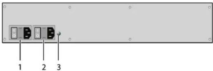
text_image
1 2 3FIGURE 2-3. 80-PORT CHASSIS, BACK VIEW
TABLE 2-6. 80-PORT CHASSIS BACK VIEW COMPONENTS
| NUMBER IN FIGURE 2-3 COMPONENT |
| 1 Connect to power supply (standard) |
| 2 Connect to power supply (redundancy) |
| 3 Grounding |
2.6.2 64-PORT CHASSIS MODELS (ACXC64, ACXC64F, ACXC64FHS, ACXC48F16)

text_image
1 2 3 4 5 6 1 2 3 4 5 6 1 2 3 4 5 6FIGURE 2-4. 64-PORT CHASSIS OPTIONS, FRONT VIEWS
TABLE 2-7. 64-PORT CHASSIS FRONT VIEW COMPONENTS
| NUMBER IN FIGURE 2-4 COMPONENT |
| 1 I/O ports #1-16 |
| 2 I/O ports #49-64 |
| 3 I/O ports #17-32 |
| 4 I/O ports #33-48 |
| 5 Serial connection (RJ-45) |
| 6 Network connection (RJ-45) |
CHAPTER 2: OVERVIEW
NEED HELP?
LE AVE THE TECH TO US
LIVE 24/7
TECHNICAL
SUPPORT
1.8 7 7.87 7.2269
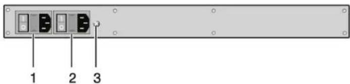
text_image
1 2 3FIGURE 2-5. 64-PORT CHASSIS, BACK VIEW
TABLE 2-8. 64-PORT CHASSIS BACK VIEW COMPONENTS
| NUMBER IN FIGURE 2-5 COMPONENT |
| 1 Connect to power supply (standard) |
| 2 Connect to power supply (redundancy) |
| 3 Grounding |
2.6.3 48-PORT CHASSIS MODELS (ACXC48, ACXC48F, ACXC48FHS, ACXC48U)

text_image
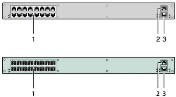
1 2 3 4 5 1 2 3 4 5FIGURE 2-6. 48-PORT CHASSIS OPTIONS, FRONT VIEWS
TABLE 2-9. 48-PORT CHASSIS FRONT VIEW COMPONENTS
| NUMBER IN FIGURE 2-6 COMPONENT |
| 1 I/O ports #1-16 |
| 2 I/O ports #17-32 |
| 3 I/O ports #33-48 |
| 4 Serial connection (RJ-45) |
| 5 Network connection (RJ-45) |
text_image
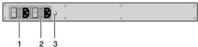
1 2 3FIGURE 2-7. 48-PORT CHASSIS, BACK VIEW
TABLE 2-10. 48-PORT CHASSIS BACK VIEW COMPONENTS
| NUMBER IN FIGURE 2-7 COMPONENT |
| 1 Connect to power supply (standard) |
| 2 Connect to power supply (redundancy) |
| 3 Grounding |
NOTE: When mounting a Compact KVM Matrix Switch with 16, 32 and 48 ports into a 19" rack, additional mounting support is recommended. It should be used in addition to the provided mounting brackets.
2.6.4 32-PORT CHASSIS MODELS (ACXC32, ACXC32F, ACXC32FHS, ACXC32U)

text_image
1 2 3 4 1 2 3 4FIGURE 2-8. 32-PORT CHASSIS OPTIONS, FRONT VIEWS
TABLE 2-11. 32-PORT CHASSIS FRONT VIEW COMPONENTS
| NUMBER IN FIGURE 2-8 COMPONENT |
| 1 I/O ports #1-16 |
| 2 I/O ports #17-32 |
| 3 Serial connection (RJ-45) |
| 4 Network connection (RJ-45) |
text_image
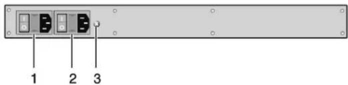
1 2 3FIGURE 2-9. 32-PORT CHASSIS, BACK VIEW
TABLE 2-12. 32-PORT CHASSIS BACK VIEW COMPONENTS
| NUMBER IN FIGURE 2-9 COMPONENT |
| 1 Connect to power supply (standard) |
| 2 Connect to power supply (redundancy) |
| 3 Grounding |
2.6.5 16-PORT CHASSIS MODELS (ACXC16, ACXC16F, ACXC16FHS, ACXC16U)
text_image
1 2 3 1 2 3FIGURE 2-10. 16-PORT CHASSIS OPTIONS, FRONT VIEWS
TABLE 2-13. 16-PORT CHASSIS FRONT VIEW COMPONENTS
| NUMBER IN FIGURE 2-10 COMPONENT |
| 1 I/O ports #1-16 |
| 2 Serial connection (RJ-45) |
| 3 Network connection (RJ-45) |
text_image
1 2 3FIGURE 2-11. 16-PORT CHASSIS, BACK VIEW
TABLE 2-14. 16-PORT CHASSIS BACK VIEW COMPONENTS
| NUMBER IN FIGURE 2-11 COMPONENT |
| 1 Connect to power supply (standard) |
| 2 Connect to power supply (redundancy) |
| 3 Grounding |
2.6.6 8-PORT CHASSIS MODELS (ACXC8, ACXC8F, ACXC8FHS, ACXC8U)

text_image
1 23 4 5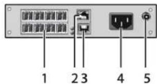
text_image
1 2 3 4 5FIGURE 2-12. 8-PORT CHASSIS OPTIONS, FRONT VIEWS
TABLE 2-15. 8-PORT CHASSIS FRONT VIEW COMPONENTS
| NUMBER IN FIGURE 2-12 COMPONENT |
| 1 I/O ports #1–8 |
| 2 Serial connection (RJ-45) |
| 3 Network connection (RJ-45) |
| 4 Connect to power supply |
| 5 Connect to 5-VDC power supply (redundancy, optional) |
2.6.7 8-PORT CHASSIS MODELS (ACXC8-M, ACXC8F-M)
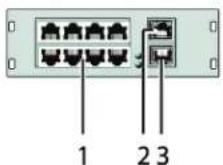
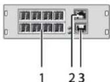
FIGURE 2-13. 8-PORT CHASSIS OPTIONS, FRONT VIEWS
TABLE 2-16. 8-PORT CHASSIS FRONT VIEW COMPONENTS
| NUMBER IN FIGURE 2-13 COMPONENT |
| 1 I/O ports #1-8 |
| 2 Serial connection (RJ-45) |
| 3 Network connection (RJ-45) |
2.7 DIAGNOSTICS AND STATUS
2.7.1 STATUS LEDS
Compact KVM Matrix Switch components are fitted with the following LEDs for overall status indication.
CPU

natural_image
Front view of a network switch device showing two ports and a labeled connection point (no text or symbols beyond the number 12)
FIGURE 2-14. STATUS LEDS, CPU AND CHASSIS FRONT VIEWS
NOTE: The CPU unit is shown in Figure 2-14 at left, and the Compact KVM Matrix Switch is shown at right.
TABLE 2-17. STATUS LEDS
| NUMBER IN FIGURE 2-14 COMPONENT |
| 1 Status LED 2 |
| 2 Status LED 1 |
TABLE 2-18. CPU STATUS LEDS FUNCTIONS
| NUMBER IN FIGURE 2-14 | LED | STATUS | DESCRIPTION |
| 1 Status LED 2 | White CPU board is in registration process | ||
| Red flashing Registration of the matrix has started | |||
| OFF | Operating condition | ||
| 2 Status LED 1 | White CPU board is in registration process | ||
| Blue flashing Registration of the matrix has started | |||
| Red flashing Registration in progress | |||
| Green flashing | Operating condition | ||
| Green | CPU board de registered | ||
NOTE: Due to variations in type, "white" might also appear as light purple or light blue.
CHAPTER 2: OVERVIEW
NEED HELP? LE AVE THE TECH TO US
LIVE 24/7 TECHNICAL SUPPORT
1.8 7 7.87 7.2269
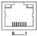
LAN PORT
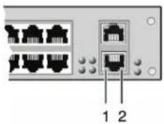
natural_image
Front view of a network switch device showing two Ethernet ports with labeled pins (no text or symbols beyond labels)FIGURE 2-15. STATUS LEDS, LAN PORT BACK VIEW
TABLE 2-19. STATUS LEDS OF THE LAN PORT
| NUMBER IN FIGURE 2-15 | LED | STATUS | DESCRIPTION |
| 1 Status 1 (orange) | ON Connection to network available | ||
| OFF No connection to network | |||
| 2 Status 2 (green) | Flashing Data traffic active | ||
| OFF Data traffic not active | |||
I/O PORTS

FIGURE 2-16. STATUS LEDS, I/O PORTS FRONT VIEW
TABLE 2-20. STATUS LEDS
| NUMBER IN FIGURE 2-16 COMPONENT |
| 1 Link Status Port 1 |
| 2 Link Status Port 2 |
TABLE 2-21. STATUS LEDS AT THE PORTS OF THE I/O BOARDS
| NUMBER IN FIGURE 2-16 | LED | STATUS | DESCRIPTION |
| 1 & 2 | Link Status | OFF Initialization | |
| Green | Connection via interconnect cable OK, data traffic active | ||
| Orange | Extender not recognized | ||
CHAPTER 2: OVERVIEW
NEED HELP? LE AVE THE TECH TO US
LIVE 24/7 TECHNICAL SUPPORT
1.8 7 7.87 7.2269
POWER SUPPLY UNIT

FIGURE 2-17. STATUS LEDS, POWER SUPPLY UNIT FRONT VIEW
TABLE 2-22. STATUS LEDS
| NUMBER IN FIGURE 2-17 COMPONENT |
| 1 Power Supply Unit 1 Status LED |
| 2 Power Supply Unit 2 Status LED |
TABLE 2-23. STATUS LEDS AT THE PORTS OF THE POWER SUPPLY UNITS
| NUMBER IN FIGURE 2-17 | LED | STATUS | DESCRIPTION |
| 1 Status PSU 1 (green) | ON Operating condition | ||
| OFF Power supply unit OFF | |||
| 2 Status PSU 2 (blue) | ON Operating condition | ||
| OFF Power supply unit OFF | |||
CHAPTER 2: OVERVIEW
NEED HELP?
LE AVE THE TECH TO US
LIVE 24/7
TECHNICAL
SUPPORT
1.8 7 7.87 7.2269
FANS


FIGURE 2-18. STATUS LEDS, FAN FRONT VIEW
TABLE 2-24. STATUS LEDS
| NUMBER IN FIGURE 2-18 COMPONENT |
| 1 Left fan status LED 1 |
| 2 Left fan status LED 2 |
| 3 Right fan status LED 2 |
| 4 Right fan status LED 1 |
TABLE 2-25. STATUS LEDS OF THE FAN TRAYS
| NUMBER IN FIGURE 2-18 | LED | STATUS | DESCRIPTION |
| 1 Left fan status 1 (red) | ON Error indication | ||
| OFF Operating condition | |||
| 2 Left fan status 2 (green) | ON Operating condition | ||
| OFF Fan OFF | |||
| 3 Right fan status 2 (green) | ON Operating condition | ||
| OFF Fan OFF | |||
| 4 Right fan status 1 (red) | ON Error indication | ||
| OFF Operating condition | |||
CHAPTER 2: OVERVIEW
2.7.2 PORT STATUS
The connections and the switching status between the various consoles and CPUs are shown in this menu.
You have the following option to access the menu:

JAVA TOOL
The current port configuration of the Compact KVM Matrix Switch is illustrated in this menu.
Select Status > Matrix View in the task area when connected to the matrix.

text_image
File Edit Device Eycles 2 Open Save Reload Connect Disconned Activate Online Configuration Save Online Changes Download... Upload... Monitoring Report... Device Finder... System Check... Save Status... 20150123114983_Demo_Config.jpg Master Status Matrix View Grid Port View Matrix Firmware EXIT Firmware Control Administration Assignment System Defective Status - Matrix View 01 02 03 04 05 06 07 08 09 10 11 12 13 14 15 16 17 18 CPU C:\ CPU Host Name: I/2 [4.9.0] Submit Wast: J/6.202.2013 Guid-View: I/2 [4.9.0] Mac Address: 08.54 (P) 02.08.08 Options Automatic Reload Show Port Numbers Gndt Parts Local Ring Show Multi-Screen Control Show Redundant Links (L1L2) ID Port Color Coding Full Access Video Access Grid Line Invalid Port No Access Fixed Port ID Port Symbols Multi-Screen Control Redundancy Clear SelectionFIGURE 2-19. STATUS—MATRIX VIEW (EXAMPLE #1)
CHAPTER 2: OVERVIEW
NEED HELP? LE AVE THE TECH TO US
LIVE 24/7 TECHNICAL SUPPORT
1.8 7 7.87 7.2269

text_image
File Edit Device Extras Open Save Reload Connect Disconnect Activate Online Configuration Save Online Changes Download Upload Monitoring Report Device Finder System Check Save Status 2010E123114803_Demo_Config.zip MASTER Status Matrix View Matrix View Grid Port View Matrix Firmware EXIT Firmware Control Administration Assignment System Definition Status - Matrix View 01 02 03 04 05 06 07 08 09 10 11 12 13 14 15 16 17 18 CPU Input Name: 115.24.4.05 Subtract Width: 295.205.205.0 Gate-up: 172.24.4.254 Max Address: 38.29.97.62.00.08 Options Automatic Reload Show Port Numbers Clear Port Local/Offshore Show Multi-Screen Control Show Redundant Line (LX, LX, LX) X3 Port Color Coding A Full Access Video Access Grid Line Invest Port No Access Panel Port X3 Port Symbols X Multi-Screen Control Y Redundancy V Cloud DirectionFIGURE 2-20. STATUS—MATRIX VIEW (EXAMPLE #2)
The colors indicate the connection status.
TABLE 2-26. STATUS LEDS
| COLOR IN FIGURES 2-19 AND 2-20 DESCRIPTION |
| Gray Port not connected |
| Yellow Video connection |
| Green KVM connection |
| Red Faulty port |
| Blue Port connected to another matrix via grid line |
CHAPTER 2: OVERVIEW
NEED HELP?
LE AVE THE TECH TO US
LIVE 24/7
TECHNICAL
SUPPORT
1.8 7 7.87 7.2269
The symbol indicates the extender that is recognized and defined at a certain port.
TABLE 2-27. SYMBOLS
| SYMBOL DESCRIPTION | |
| Port connected to a CPU Unit | |
| Port is connected to a CPU Unit that is switched to a CON Unit in Private Mode | |
| Port connected to a CON Unit | |
| Port connected to a CON Unit with Shared Access to a CPU | |
| Port is connected to a CON Unit that is connected to a CPU Unit in Private Mode | |
| Port connected to a USB 2.0 CPU Unit | |
| Port connected to a USB 2.0 CON Unit | |
| Port is configured as Cascade-CON port for cascading of matrices | |
| Port is configured as Cascade-CPU port for cascading of matrices | |
| Port is a UNI port of an I/O board that can be used for USB 3.0 or SDI switching | |
| UNICON | UNI port is configured as CON port to connect USB 3.0 CON extenders, for example |
| UNICPU | UNI port is configured as CPU port to connect USB 3.0 CPU extenders, for example |
NOTES:
- Red framed ports are defined as "fixed" (e. g. for USB 2.0 connections).
- The port with four static blue squares is currently selected.
If a port is selected, all other ports are transparent, except those connected to the currently selected port. To clear a selection, press the Clear Selection button.
In Matrix View, a red cross on a port indicates that the console to be connected does not have access rights to the respective CPU at this port.
Press the left mouse button to show the extender information of the currently selected port on the right hand side of the working area.
The following information is available:
TABLE 2-28. EXTENDER INFORMATION OF THE CURRENTLY SELECTED PORT
| FIELD DESCRIPTION | |
| Extender Name Name of selected extender | |
| Extender Type Type of selected extender | |
| Port ID Number of selected port | |
| Device Name Name of connected console or CPU | |
| Connections | Listing of assigned connections to marked port (Full Access or Video Access) |
Press the right mouse button to open the context menu with additional functions for the currently selected port.
The following functions are available:
TABLE 2-29. CONTEXT FUNCTIONS
| FUNCTION | DESCRIPTION |
| Open Extender | The menu for definition of the currently selected extender will be opened |
| Open Device | The menu for definition of the currently selected console or CPU will be opened |
| Switch | The menu for execution of switching operations will be opened |
CHAPTER 2: OVERVIEW
To reload the Matrix View, you have the following options:
- Press
on a connected keyboard
◆ Execute Edit > Reload in the menu bar - Press the Reload button in the tool bar
2.7.3 PORT STATUS MATRIX GRID
In this menu, the connections and the switching status between the various CON and CPU Devices are shown within the Matrix Grid.
The port view is divided into the different Grid matrices. As a result, each matrix is displayed in an optimized view of 24 ports per line to be able to show also a larger number of ports.
You have the following option to access the menu:

JAVA TOOL
The current port configuration of the Matrix Grid is illustrated in this menu.
Select Status > Grid Port View in the task area when connected to the matrix.
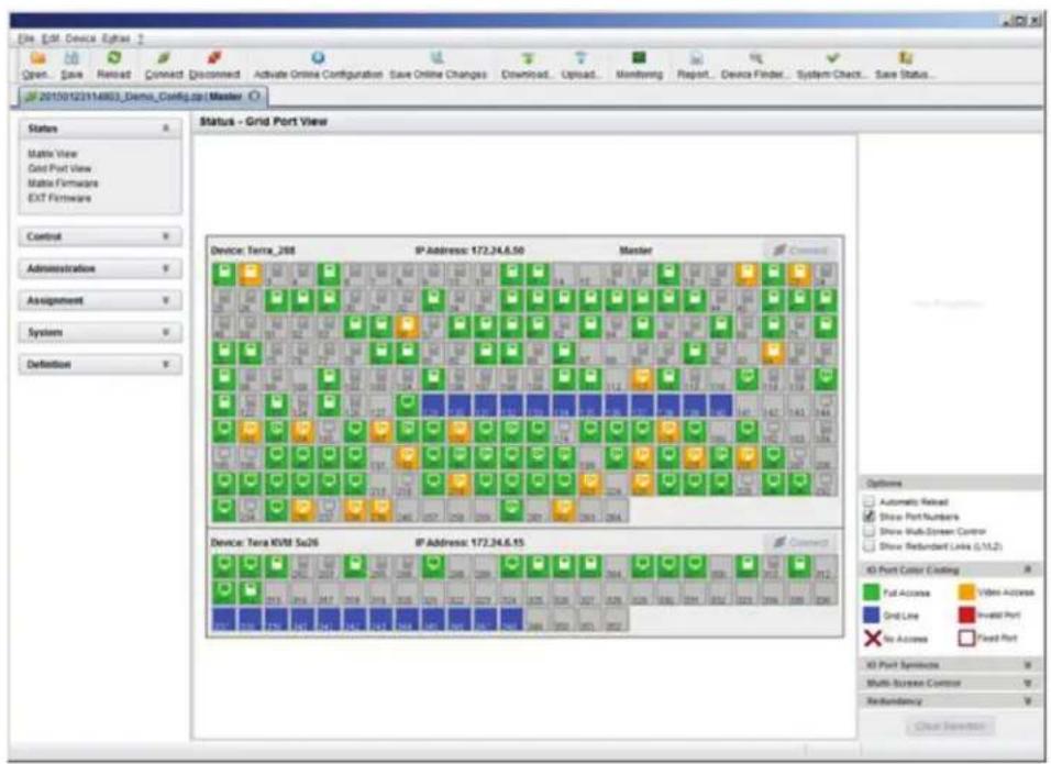
text_image
File: ESM Device Egrase Open Save Reload Connect Disconnected Activate Online Configuration Save Online Changes Download Upload Monitoring Report Device Finder System Check Save Status 20150123114803_Demo_Config.zip | Master Status Grid Port View Status - Grid Port View Matrix View Grid Port View Matrix Firmware EXT Firmware Control Administration Assignment System Definition Device: Terra_268 IP Address: 172.24.6.50 Master Device: Terra_KVM Su26 IP Address: 172.24.6.15 Connect Device: Terra_268 IP Address: 172.24.6.50 Master Device: Terra_268 IP Address: 172.24.6.15 Options Automatic Reload Show Port Numbers Show Multi-Screen Control Show Reboundant Links (S/11.2) X3 Port Color Coding Full Access Video Access Grid Line Invest Port No Access Fixed Port X3 Port Symbols Multi-Screen Control Redundancy Check InsertionFIGURE 2-21. STATUS—GRID PORT VIEW
CHAPTER 2: OVERVIEW
NEED HELP? LE AVE THE TECH TO US
LIVE 24/7 TECHNICAL SUPPORT
1.8 7 7.87 7.2269
NOTE: Functions, colors and symbols used in the Grid Port View are identical to those in the port status of the Matrix View.
2.7.4 EXTENDER OSD
All extenders used with the Compact KVM Matrix Switch are provided with their own OSD to display the connection status of the console.
CON 010148887
CPU : 01002 CPU_010148543
ACCESS : Full Access
SHARES:1 device(s)
FIGURE 2-22. EXTENDER OSD
CHAPTER 2: OVERVIEW
NEED HELP?
LE AVE THE TECH TO US
LIVE 24/7
TECHNICAL
SUPPORT
1.8 7 7.87 7.2269
The following information is shown in the OSD menu:
TABLE 2-30. OSD MENU INFORMATION
| FIELD DESCRIPTION | |
| CON Name of console | |
| CPU | Name of currently connected CPUColor Coding:Green: The connection to the selected CPU is completely established.Yellow: The connection to the selected CPU is partially established.Red: The connection to the selected CPU cannot be established.NOTE: Possible reasons for any incomplete or non-established connection can be switched off extenders or insufficiently available Grid lines in Matrix Grid operation. |
| ACCESS | Full Access: Console has a KVM connection to the displayed CPU.Video Access: Console has a video only connection to the displayed CPU.Private Mode: Console has a Private Mode connection to the displayed CPU.not connected: Console is not connected to a CPU. |
| SHARED | x device(s) shows the exact number of devices that are connected to the current CPU of the console (e.g. 3 devices).If the field remains empty, no other devices are connected to the current CPU. |
NOTE: If the options Mouse Connect or Keyboard Connect are used, the name of the console with keyboard / mouse control will be displayed on those consoles that do not have current K/M control. The console is displayed in yellow under Access.
CHAPTER 2: OVERVIEW
NEED HELP? LE AVE THE TECH TO US
LIVE 24/7 TECHNICAL SUPPORT
1.8 7 7.87 7.2269
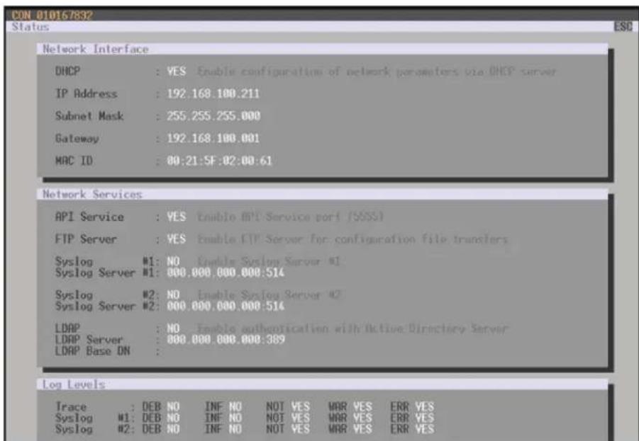
2.7.5 NETWORK STATUS
The current network configuration is shown in this menu.
You have the following options to access the menu:


The following information is shown in this menu:
TABLE 2-31. NETWORK CONFIGURATION
| FIELD DESCRIPTION | |
| DHCP | Information whether the network settings are applied dynamically. Display Y (Yes) or N (No) |
| IP Address Information about the IP address as provided manually or via DHCP | |
| Subnet Mask Information about the subnet mask as provided manually or via DHCP | |
| Gateway Information about the gateway address as provided manually or via DHCP | |
| MAC ID Information about the MAC address of the matrix | |
OSD
Select Status > Network in the main menu.
text_image
CON 010167832 Status ESO Network Interface DHCP : YES Enable configuration of network parameters via DHCP server IP Address : 192.168.100.211 Subnet Mask : 255.255.255.000 Gateway : 192.168.100.001 MAC ID : 00:21:5F:02:00:61 Network Services API Service : YES Enable API Service port (SSSS) FTP Server : YES Enable FTP Server for configuration file transfers Syslog #1: NO Enable System Server #1 Syslog Server #1: 000.000.000.000:514 Syslog #2: NO Enable System Server #2 Syslog Server #2: 000.000.000.000:514 LDAP : NO Enable authentication with Active Directory Server LDAP Server : 000.000.000.000:389 LDAP Base DN : Log Levels Trace : DEB NO INF NO NOT YES WAR YES ERR YES Syslog #1: DEB NO INF NO NOT YES WAR YES ERR YES Syslog #2: DEB NO INF NO NOT YES WAR YES ERR YESFIGURE 2-23. STATUS>NETWORK
CHAPTER 2: OVERVIEW
NEED HELP? LE AVE THE TECH TO US
LIVE 24/7 TECHNICAL SUPPORT
1.8 7 7.87 7.2269
JAVA TOOL
- Select Status > Network in the task area.

text_image
File Edit Device Express Open Save Reload Connect Disconnect Activate Online Configuration Save Online Changes Download Upload Monitoring Report Device Finder System Check Save Status 2015E123114903_Demo_Config.pocMaster Status Matrix View Grid Port View Matrix Firmware EXT Firmware Control Administration Assignment System Definition Status - Matrix View 01 02 03 04 05 06 07 08 09 10 11 12 13 14 15 16 17 18 CPU 01 02 03 04 05 06 07 08 09 10 11 12 13 14 15 16 17 18 01 02 03 04 05 06 07 08 09 10 11 12 13 14 15 16 17 18 01 02 03 04 05 06 07 08 09 10 11 12 13 14 15 01 02 03 04 05 06 07 08 09 10 11 12 13 14 01 02 03 04 05 06 07 08 09 10 11 12 01 02 03 04 05 06 07 01 02 03 04 05 06 01 02 03 04 01 02 03 01 02 03 04 05 06 07 08 09 10 11 12 13 14 15 16 17 18 CPV Host Name: TSS4.9.85 Subnet Wear: AHT.266.278.3 Oset-up: TSS4.9.85 Max Address: BGT.99.99.99.99.99.99.99.99.99.99.99.99.99.99.99.99.99.99.99.99.99.99.99.99.99.99.99.99.99.99.99.99.99.99. Options Automatic Reload Show Port Numbers Grid Route Local Track Show Multi-Screen Control Show Redundant Line (LTL2) X3 Port Color Cooling Full Access Video Accounts Grid Line Invest Port No Access Fixed Port X3 Port Symbols Multi-Screen Control Rebuildancy Clear DirectionFIGURE 2-24. STATUS—MATRIX VIEW
- Use the left mouse button to click on the network port of the CPU board. The corresponding network status will be shown on the right hand side of the working area.
The available information can be faded in or hidden by pressing the left mouse button on the "plus" or "minus" icon.
CHAPTER 2: OVERVIEW
NEED HELP? LE AVE THE TECH TO US
LIVE 24/7 TECHNICAL SUPPORT
1.8 7 7.87 7.2269
2.7.6 FIRMWARE STATUS MATRIX
The current firmware status of the installed boards is shown in this menu.
You have the following options to access the menu:


The following information is shown in this menu:
TABLE 2-32. FIRMWARE STATUS INFORMATION
| FIELD DESCRIPTION |
| Name Description of modules |
| Type Type number |
| Ports Number of ports |
| Version Complete description of firmware version |
| Date Date of firmware version |
| Status Module status |
OSD
Select Status > Firmware in the main menu.

text_image
B3000 CON B10123614 Status Firmware Slot Firmware 00 01 108SFP 108 8 F02.02 09.08.11 02 108SFP 108 8 F02.02 09.08.11 03 108SFP 108 8 F02.02 09.08.11 06 108CAT 108 8 F02.02 09.08.11 10 108SFP 108 8 F02.02 09.08.11 13 108CAT 108 8 F02.02 09.08.11 30 108SFP 108 8 F02.02 09.08.11 SUTCH WFIGURE 2-25. STATUS—FIRMWARE
CHAPTER 2: OVERVIEW
NEED HELP? LE AVE THE TECH TO US
LIVE 24/7 TECHNICAL SUPPORT
1.8 7 7.87 7.2269
JAVA TOOL
- Select Status > Matrix Firmware in the task area.

text_image
Status - Matrix Firmware State Name Type Ports Serial Number Version Date Status TEMPA_786 States 268 000000000 00 MATQG8 CPU 1 000000000 F53.05 2014-09-21 Available MATXCM QSD 1 A31.14 2014-02-25 MATXMO HO HD 2 F53.08 2014-08-18 01 MATXCAT XIR 0 000000000 B53.00 2014-09-21 Available MATXSDQ USD 8 F53.23 2014-04-04 02 MATXCAT XIR 0 000000000 B53.90 2014-09-21 Available MATXSDQ USD 8 F53.23 2014-04-04 03 MATXCAT XIR 0 000000000 B53.86 2014-09-21 Available MATXSDQ USD 8 F53.23 2014-04-04 04 MATXCAT XIR 0 000000000 B53.99 2014-09-21 Available MATXSDQ USD 8 F53.23 2014-04-04 05 MATXCAT XIR 0 000000000 B53.99 2014-09-21 Available MATXSDQ USD 8 F53.23 2014-04-04 06 MATXCAT XIR 0 000000000 B53.99 2014-09-21 Available MATXSDQ USD 8 F53.23 2014-04-04 07 MATXCAT XIR 0 000000000 B53.99 2014-09-21 Available MATXSDQ USD 8 F53.23 2014-04-04 08 MATXCAT XIR 0 000000226 B53.99 2014-09-21 Available MATXSDQ USD 8 F53.23 2014-04-04 09 MATXCAT XIR 0 688888888 B53.99 2014-09-21 Available MATXSDQ USD 8 F53.23 2014-04-04 10 MATXCAT XIR 6 688888888 B53.99 2014-09-21 Available MATXSDQ USD 8 F53.23 2014-04-04 11 MATXCAT XIR 6 688888888 B53.99 2014-09-21 Available MATXSDQ USD 8 F53.23 2014-04-04 12 MATXCAT XIR 6 688888888 B53.99 2014-09-21 Available MATXSDQ USD 8 F53.23 2014-04-04 13 MATXCAT XIR 6 688888888 B53.99 2014-09-21 AvailableFIGURE 2-26. STATUS—MATRIX FIRMWARE
- To read out the overall status of the matrix and store it locally (file extension .zip), select Matrix > Save Status or press the respective button in the symbol bar.
The various modules can expanded and retracted in the Name column by clicking with the left mouse button on the plus or minus symbols.
By clicking on the plus or minus symbol in the upper right corner of the working area you can expand and retract all module information with one click of the left mouse button.
CHAPTER 2: OVERVIEW
NEED HELP? LE AVE THE TECH TO US
LIVE 24/7 TECHNICAL SUPPORT
1.8 7 7.87 7.2269
2.7.7 FIRMWARE STATUS EXTENDER
The current firmware status of connected extenders is shown in this menu.
You have the following option to access the menu:

The following information is shown in this menu:
TABLE 2-33. FIRMWARE STATUS OF CONNECTED EXTENDERS INFORMATION
| FIELD DESCRIPTION |
| Name Description of firmware |
| Type Description of extender module |
| Ports Number of ports |
| Cur. Version Description of current firmware version |
| Cur. Date Date of current firmware version |
Select Status > Firmware in the task area.

text_image
Ext. Ext. Device Options Open... Save... Reload... Connect... Disconned... Activate Online Configuration... Save Online Changes... Download... Upload... Monitoring... Report... Device Finder... System Check... Save Status... 20150123114903_Demo_Config.py?Master Status Matls View Grid Port View Matls Firmware EXT Firmware Control Administration Assignment System Definition Status - EXT Firmware Extender Firmware: Extender Firmware on ISO Board Extender View Component view ID Name Port Type Version Date TENMA_206 Tera_205 Matrix 10/03/07 LH2_115_1_1 1 CPU UNIT EXTCPU EXT FIO_28 2014-02-05 HDCPU HD FIO_23 2014-02-04 EXTMD MSD 2014-06-02 02 10/03/07 LH2_102_1_1 2 CPU UNIT EXTCPU EXT FIO_29 2014-02-05 HDCPU HD FIO_23 2014-02-04 EXTMD MSD 2014-06-02 03 10/03/07 LH2_101_3_1 3 CPU UNIT EXTCPU EXT FIO_28 2014-02-05 HDCPU HD FIO_23 2014-02-04 EXTMD MSD 2014-06-02 04 4/03/1/09 LH2_115_6_1 4 CPU UNIT EXTCPU EXT FIO_28 2014-02-05 HDCPU HD FIO_23 2014-02-04 EXTMD MSD 2014-06-02 05 10/13/07 LH2_ST_2_1 5 CPU UNIT EXTCPU EXT FIO_28 2014-02-05 HDCPU HD FIO_23 2014-02-04 EXTMD MSD 2014-06-11 Extender firmware version conflict Manual update of EXTMSD / EXTMSD recommended Wrong module type (CPUCON normalitz) Undefined typeFIGURE 2-27. STATUS—EXT FIRMWARE
2.8 TRACE FUNCTION
All events, e.g. activities and switching operations of the Compact KVM Matrix Switch are logged and displayed in this menu.
This function is used for diagnostic purposes.
You have the following option to request various trace views in the menu:

The following information is shown in this menu:
TABLE 2-34. TRACE FUNCTION MENU
| FIELD DESCRIPTION |
| Date Date stamp |
| Time Time stamp |
| Message Detailed description of the event |
Trace possibilities:
- Select Status > Trace IO Board in the main menu to check the events on your current I/O board.
- Select Status > Trace Matrix to check the matrix events.
2.9 SYSLOG MONITORING
The complete logging of the Compact KVM Matrix Switch activities, switching operations and surveillance of the function of critical components such as fans or power supply units takes place in this menu.
You have the following option to access the menu:

To start Syslog Monitoring, proceed as follows:
- Select the Monitoring symbol in the symbol bar.

text_image
File Edit Device Eptos Open... Save... Reload... Connect Document... Activate Online Configuration... Save Online Changes... Download... Upload... Monitoring... Report... Device Finder... System Check... Save Status... 20150123114903_Demo_Config.jsp Master Monitoring Status - Syslog Filter Find Data File Date: 10/06/15 11:34:25 Time: 10:06:15 11:34:25 Facility Severity Host Message Filter Clear Data Facility Severity Host App Name Proc ID Mag ID Message 2014-07-02T12:47:24.958 user NOTICE MAIN CPU - NOT switchAndSetCpuc (CPU=1029 CON=3024) 2014-07-02T12:47:15.820 user INFO MAIN CPU - INF msGetOutputPrint (OUT=150 Rs=50) 2014-07-02T12:47:15.400 user INFO MAIN CPU - INF swConnectedCpuc (CPU=1029 CON=3020) 2014-07-02T12:47:15.420 user INFO MAIN CPU - INF swDissconnectCpuc(UTC) CPU=1029 2014-07-02T12:47:15.450 user NOTICE MAIN CPU - NOT switchAndSetCpuc (CPU=1029 CON=3030) 2014-07-02T12:45:02.450 user INFO MAIN CPU - INF msGetOutputPrint (OUT=150 Rs=5) 2014-07-02T12:45:02.450 user INFO MAIN CPU - INF swConnectedCpuc (CPU=1029 CON=3024) 2014-07-02T12:45:02.450 user NOTICE MAIN CPU - NOT switchAndSetCpuc (CPU=1029 CON=3024) 2014-07-02T12:44:55.390 user INFO MAIN CPU - INF msGetOutputPrint (OUT=43 Rs=57) 2014-07-02T12:44:55.390 user INFO MAIN CPU - INF msGetOutputPrint (OUT=67 Rs=43) 2014-07-02T12:44:56.390 user INFO MAIN CPU - INF swConnectedCpuc(UTC) CPU=1059 CON=3041 2014-07-02T12:44:55.375 user INFO MAIN CPU - INF msGetOutputPrint (OUT=43 Rs=5) 2014-07-02T12:44:56.375 user INFO MAIN CPU - INF swDissconnect(CCpuc) CPU=3041 2014-07-02T12:44:56.368 user INFO MAIN CPU - INF msGetOutputPrint (OUT=134 Rs=6) 2014-07-02T12:44:56.368 user INFO MAIN CPU - INF swDissconnect(Cpuc) CPU=1052 2014-07-02T12:44:56.368 user NOTICE MAIN CPU - NOT switchAndSetCpuc(CCpuc) CPU=1066 CON=304 2014-07-02T12:44:56.735 user INFO MAIN CPU - INF msGetOutputPrint (OUT=153 Rs=50) 2014-07-02T12:44:56.735 user INFO MAIN CPU - INF swConnectedCpuc (CPU=1029 CON=3039) Save Trace Clear Trace PauseFIGURE 2-28. MONITORING—SYSLOG
Logging of system activities starts when the Monitoring menu is opened and remains active until the tab is closed.
NOTE: Syslog messages are transmitted via UDP. Therefore, port 514 within the used network should not be blocked, e.g. by a firewall.
During logging, the activities are written continuously into logging files and stored locally. This process can be set with various options.
CHAPTER 2: OVERVIEW
NEED HELP?
LE AVE THE TECH TO US
LIVE 24/7
TECHNICAL
SUPPORT
1.8 7 7.87 7.2269
OPTIONS
- Select Extras > Options in the menu bar and open the tab.
The following options are available:
TABLE 2-35. SYSLOG OPTIONS
| OPTION DESCRIPTION | |
| Log File Directory Default directory to store the log files | |
| Log File Name Default name of the log file | |
| Log File Extension Default extension for the log file | |
| Daily Log files Log files are stored every 24 hours (daily) | |
| Maximum Log File Size (KB) Allowed maximum size of log file | |
| Maximum Number of Log Files | Allowed maximum number of log files |
| Autostart | When starting the Java Tool, the Syslog function will be started in the background |
| Open Monitoring Tab | When starting the Java Tool, the Monitoring tab will be opened |
NOTE: When reaching the maximum log file size, a new log file will be created. When reaching the maximum number of log files, the oldest one will be overwritten with the new information.
FILTER FUNCTION
To filter relevant messages out of a number of logged activities of the Compact KVM Matrix Switch, the Syslog Monitoring offers various filter options.
To set and activate a filter, proceed as follows:
- Set the desired filter option(s) by activating the respective checkbox(es).
- Activate the filter settings by pressing the Filter button.
- To deactivate an activated filter setting, press the Clear button.
The following filter options are available:
TABLE 2-36. FILTER OPTIONS
| OPTION | DESCRIPTION |
| Date | Messages for a defined date range will be filtered |
| Facility | Messages for a defined facility will be filtered |
| Severity | Messages for a defined severity will be filtered |
| Host | Messages for a defined host will be filtered |
| Message | Messages with defined text parts will be filtered |
NOTE: Filter options are not valid within the locally stored log files.
CHAPTER 2: OVERVIEW
NEED HELP?
LE AVE THE TECH TO US
LIVE 24/7
TECHNICAL
SUPPORT
1.8 7 7.87 7.2269
RECORDING FUNCTION
All messages shown in the Syslog are equipped with various recording functions.
◆ To store messages shown in the Syslog (filtered or unfiltered), press the Save trace button. The messages will be stored in a .txt file.
- To remove messages shown in the Syslog, press the Clear trace button.
- To stop recording messages, press the Pause button. To continue, press the button again.
2.10 SNMP
The SNMP function allows all function-critical and safety-critical elements of the matrix to be monitored and queried. This function complies with the RFC 1157 standard.
NOTE: When using SNMP monitoring, we recommend using a dedicated network to maintain continuous access.
You have the following options to configure the SNMP monitoring:


OSD
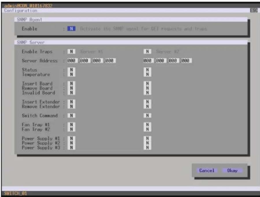
To activate the SNMP agent, proceed as follows:
- Select Configuration > SNMP in the main menu.
CHAPTER 2: OVERVIEW
NEED HELP? LE AVE THE TECH TO US
LIVE 24/7 TECHNICAL SUPPORT
1.8 7 7.87 7.2269
text_image
admin@CON 010167832 Configuration ESC SNMP Agent Enable : N Activate the SNMP agent for GET requests and traps SNMP Server Enable Traps : N Server #1 N Server #2 Server Address : 000 000 000 000 000 000 000 000 Status : N N Temperature : N Insert Board : N N Remove Board : N N Invalid Board : N N Insert Extender : N N Remove Extender : N N Switch Command : N N Fan Tray #1 : N N Fan Tray #2 : N N Power Supply #1 : N N Power Supply #2 : N N Power Supply #3 : N N Cancel Okay SWITCH_01FIGURE 2-29. CONFIGURATION—SNMP
- Set the Enable option to Y (Yes) under SNMP Agent. By activating this option, the permission for an active query of the SNMP agent is granted.
To configure an SNMP server, proceed as follows:
- Select Configuration > SNMP in the main menu.
- Set the Enable Traps option to Y (Yes) within SNMP Server. This function allows an active transmission of trap messages from the SNMP agent to the SNMP server.
- Set the IP address of the SNMP server within Server Address.
- Activate the requested traps by enabling them to Y (Yes).
You can select the following traps:
TABLE 2-37. TRAPS
| TRAP DESCRIPTION | |
| Status Notification about matrix status | |
| Temperature Notification about temperature within the matrix | |
| Insert Board Notification about insertion of a new I/O board into a slot | |
| Remove Board Notification about removal of an I/O board out of a slot | |
| Invalid Board Notification about a faulty I/O board | |
| Insert Extender | Notification about a newly connected extender to the matrix, notification about a switched on extender, notification about a newly established link between extender and matrix |
| Remove Extender | Notification about a removed extender from the matrix, notification about a switched off extender, notification about an interrupted link between extender and matrix |
| Switch Command Notification about a performed switching operation at the matrix | |
| Fan Tray #1 Notification about the status of fan tray #1 | |
| Fan Tray #2 | Notification about the status of fan tray #2 |
| Power Supply #1 | Notification about the status of power supply unit #1 |
| Power Supply #2 | Notification about the status of power supply unit #2 |
| Power Supply #3 | Notification about the status of power supply unit #3 |
To query the SNMP status, proceed as follows:
- Select Status > SNMP in the main menu.
NOTE: To activate the SNMP agent function or the SNMP server function, you must restart the matrix.
Two SNMP servers can be used at the same time.
CHAPTER 2: OVERVIEW
NEED HELP? LE AVE THE TECH TO US
LIVE 24/7 TECHNICAL SUPPORT
1.8 7 7.87 7.2269
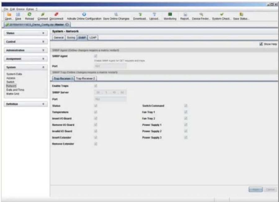
JAVA TOOL
To activate the SNMP agent, proceed as follows:
- Select System > Network in the task area.
text_image
Open... Save Reload Closed Disconnect Activate Online Configuration Save Online Changes Download... Upload... Monitoring Report... Device Finder... System Check... Save Status... 20150418111823_Demo_Config.py Master Status Control Administration Assignment System System Data Access Switch Network Date and Time Matrix Grid Definition System - Network General Setup SIMP LDAP Show Help SMBP Agent (Online charges require a matrix restart) SMBP Agent Device SIMP Agent for SET requests and traps Port SMBP Trap (Online charges require a matrix restart) Trap Receiver 1 Trap Receiver 2 Enable Traps SMBP Server Port Status Switch Command Temperature Fan Tray 1 Insert IO Board Fan Tray 2 Remove IO Board Power Supply 1 Insolid IO Board Power Supply 2 Insert Extender Power Supply 3 Remove Extender CancelFIGURE 2-30. SYSTEM-NETWORK
- Activate the SNMP Agent option in the SNMP tab. By activating this option, the permission for an active query of the SNMP agent is granted.
To configure an SNMP server, proceed as follows:
- Select Configuration > Network in the task area.
- Activate the Enable Traps option within SNMP Server. This function allows an active transmission of trap messages from the SNMP agent to the SNMP server.
- Set the IP address of the SNMP within SNMP Server.
• Activate the requested traps.
NOTE: To activate the SNMP agent function or the SNMP server function, you must restart the matrix.
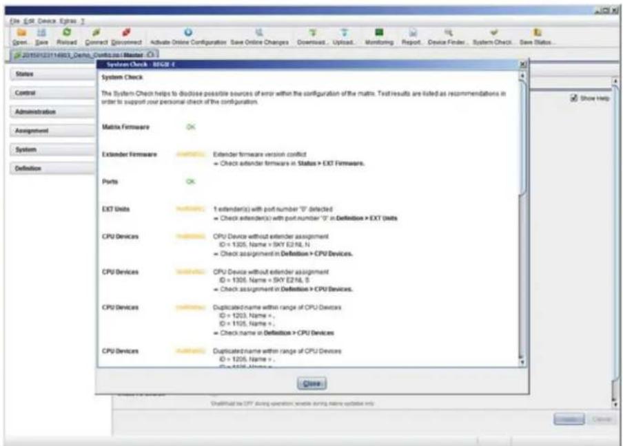
2.11 SYSTEM CHECK
System Check offers a diagnostic function for checking the matrix configuration. The feature indicates suboptimal and faulty settings.
System Check is exclusively used for a confidence check and does not make any active changes in the configuration.
You have the following option to access the menu:

The following configuration parts are checked:
Matrix Firmware
◆ Extender Firmware
- Multi-Screen Control
Ext Units
CPU Devices
CON Devices
User
- System Configuration
Matrix Grid
The following notification levels can be shown:
TABLE 2-38. NOTIFICATION LEVELS
| LEVEL DESCRIPTION | |
| OK (green) System Check completed without any abnormalities | |
| WARNING (yellow) | System Check revealed abnormalities in the configuration that point to incomplete parts of the configuration, firmware differences, duplications or unconnected extenders but without being system critical |
| ERROR (red) | System Check revealed errors in the configuration that can have both functional and system-critical influences on the system |
NOTE: If the messages "WARNING" and "ERROR" are generated by the System Check function, the respective problem will be described and a basic guideline will be provided.
CHAPTER 2: OVERVIEW
NEED HELP? LE AVE THE TECH TO US
LIVE 24/7 TECHNICAL SUPPORT
1.8 7 7.87 7.2269
To start System Check, proceed as follows:
- Select the System Check symbol in the symbol bar.
text_image
System Check - ESCB 4 System Check The System Check helps to disclose possible sources of error within the configuration of the matrix. Test results are listed as recommendations in order to support your personal check of the configuration. Matrix Firmware Extender Firmware Extender firmware version conflict + Check extender firmware in Status > EXT Firmware. Ports EXT Units 1 extender(s) with port number "0" deflected + Check extender(s) with port number "0" in Definition > EXT Units CPU Devices CPU Device without extender assignment ID = 1305, Name = SKY E2NIL N + Check assignment in Definition > CPU Devices. CPU Devices CPU Device without extender assignment ID = 1306, Name = SKY E2NIL S + Check assignment in Definition > CPU Devices. CPU Devices Duplicated name within range of CPU Devices ID = 1203, Name =, ID = 1105, Name =, + Check name in Definition > CPU Devices CPU Devices Duplicated name within range of CPU Devices ID = 1206, Name =, ID = 1106, Name =, Close OneVirtual is CRT during operation, create running online update onlyFIGURE 2-31. SYSTEM CHECK
2.12 DEVICE FINDER
The Device Finder offers the possibility to find all matrices or SNMP boards that are located in the same subnetwork. This is useful, for example, if the IP address of a specific matrix is unknown and should be accessed via IP.
You have the following option to access the function:

The following device information is shown in the Device Finder:
TABLE 2-39. DEVICE INFORMATION
| INFORMATION DESCRIPTION |
| Device Name of device |
| Name Name of the active configuration |
| IP Address Current IP address of the device |
| MAC Address MAC address of the device |
| Type Type of device |
CHAPTER 2: OVERVIEW
NEED HELP? LE AVE THE TECH TO US
LIVE 24/7 TECHNICAL SUPPORT
1.8 7 7.87 7.2269
NOTE: You can use the last column of the Device Finder to access the respective matrix directly using the Connect button.
To start the Device Finder, proceed as follows:
- Select the symbol Device Finder in the symbol bar.
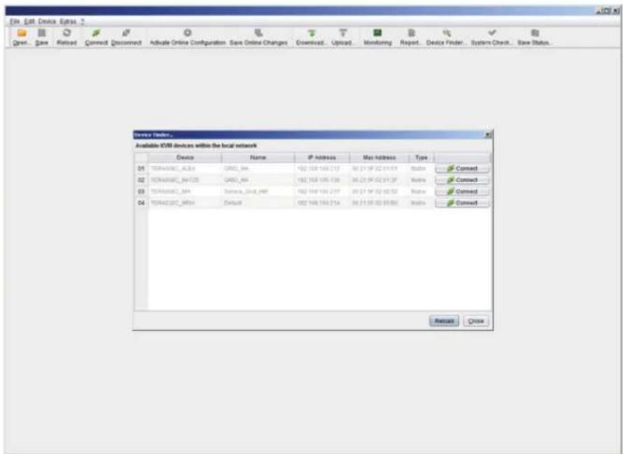
text_image
Open - Save Retired Connect: Disconnect Activate Online Configuration: Save Online Changes Download... Upload Monitoring Report... Device Finder... System Check... Save Status... Device Finder... Available XSM devices within the local network Device Name IP Address Mac Address Type 04 TERMASSC_AU2A GROD_AHA 192 168 190.217 30.21.5F 02.01.5F Address Connect 02 TERMASSC_BHT2E GROD_AHA 192 168 190.130 30.21.5F 02.01.3F Address Connect 03 TERMASSC_BHA Service_CN48_249 192 168 190.217 30.21.5F 02.02.52 Address Connect 04 TERMASSC_MTHA Default 192 168 190.214 30.21.5F 02.03.802 Address Connect Reset CloseFIGURE 2-32. DEVICE FINDER
3.1 PACKAGE CONTENTS
Your package contains the following items:
(1) Compact KVM Matrix Switch
(1) power cord per built-in power supply unit
(1) RJ-45/RS-232 adapter
- Mounting accessories
(1) Quick Start Guide
If anything is missing or damaged, contact Black Box Technical Support at 877-877-2269 or info@blackbox.com.
3.2 SYSTEM SETUP
NOTE: We recommend that first-time users set up the system in the same room as a test setup. This will allow you to identify and solve any cabling problems, and experiment with your system more conveniently.
NOTE: Because of the construction of the matrix chassis, we recommend that you use an additional subfloor below the matrix if you are using it in a 19" rack.
MATRIX SETUP
- Connect a CON Unit to an I/O port of the matrix for its configuration.
- Connect keyboard, mouse and monitor to the CON Unit.
- Connect the matrix and the CON Unit to the power supply.
- Open OSD via keyboard command
, and log in with administrator rights in the main menu under configuration (see Section 4.2.1). - Configure initially as requested.
NOTE: After you configure the system, we recommend that you save the configuration by selecting Configuration > Save and restart the matrix by selecting Restart Matrix.
- Optional: Establish a network connection between the matrix and the Java Tool so you can set an extended configuration (see Section 4.2.2).
The default IP address is 192.168.100.99 and DHCP is deactivated. When installing several matrices at the same time, we strongly recommend that you install them in sequence and to assign unique IP addresses in order to avoid IP address conflicts.
EXTENDER SETUP
- Connect the CON Units to the matrix by using the interconnect cables (CATx).
- Connect the CON Units to the input devices to be used (for example, keyboard and mouse).
- Connect the 5-VDC power supply units to the CON Units.
- Check the basic function of the CON Unit by opening the OSD via keyboard command
, . - Connect the source (computer, CPU) to the CPU Unit of the extender using the provided connection cables.
- Connect the CPU Unit to the matrix using the interconnect cables (CATx).
CHAPTER 3: INSTALLATION
NEED HELP?
LE AVE THE TECH TO US
LIVE 24/7
TECHNICAL
SUPPORT
1.8 7 7.87 7.2269
- Connect the 5-VDC power supply units to the CPU Units.
- Start the system.
3.3 EXAMPLE APPLICATIONS
The Compact KVM Matrix Switch supports a wide and flexible range of system configurations:
A part of the Compact KVM Matrix Switch can be configured as a Single-Head work station, a part as Dual-Head, as Quad-Head or even as a video matrix for example. In addition to that, there are configurations with KVM and USB 2.0 available.
In addition to OSD access by a keyboard connected to the CPU board or and extender CON Unit, other methods of control are available, including:
Java Tool
- Serial interface
A connection to common media controls is also possible.
The following sections show typical example installations of the Compact KVM Matrix Switch.
3.3.1 KVM MATRIX
In Single-Head mode, up to 48 ports can be used either as an input or as an output port depending on components and equipment. Non-blocking access is available for all users, i.e. user access is not limited by the activities of another user.

flowchart
graph TD
    A["Server 1"] --> B["Server 2"]
    C["Server 3"] --> D["Server 4"]
    E["Server 5"] --> F["Server 5"]
    G["Server 6"] --> H["Computer 1"]
    I["Server 7"] --> J["Server 8"]
FIGURE 3-1. KVM MATRIX INSTALLATION EXAMPLE
TABLE 3-1. SINGLE-HEAD KVM MATRIX INSTALLATION COMPONENTS
| NUMBER IN FIGURE 3-1 COMPONENT |
| 1 Source (computer, CPU) |
| 2 CPU Unit |
| 3 Interconnect cable |
| 4 Compact KVM Matrix Switch |
| 5 CON Unit |
| 6 Console (monitor, keyboard, mouse) |
If you have a Single-Head console, you can also get access to a Dual-Head or Quad-Head console for example. However, control is only possible at monitor 1.
Any signal source can be switched to any number of monitors that will show the video signal at the same time. Audio may also be switched if required.
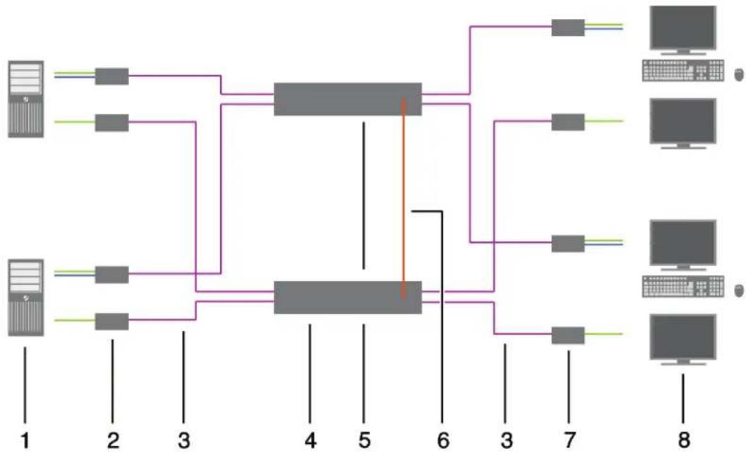
If you have special configurations, especially at installations with several monitors per workstation or additional support of USB 2.0 transmission paths, the number of connectable CPUs and consoles can be increased by a parallel operation (stacking) of several Compact KVM Matrix Switches.
One Compact KVM Matrix Switch is defined as the Master Matrix and its IP address entered into the Master IP Address field (see Section 4.4.1). All other matrices are defined as Sub Matrices. Sub matrices must be connected to the master matrix via a network connector (RJ-45) on the CPU board. The Enable LAN Echo option has to be activated at the master matrix (see Section 4.4.1).
If a switching command is performed using the OSD, the synchronized matrices will also switch automatically.
NOTE: Switching of stacked devices might be delayed by several seconds.
flowchart
graph TD
    A["Server 1"] --> B["Router 1"]
    C["Server 2"] --> D["Router 2"]
    E["Server 3"] --> F["Router 3"]
    G["Server 4"] --> H["Switch 4"]
    I["Server 5"] --> J["Switch 5"]
    K["Server 6"] --> L["Switch 6"]
    M["Server 7"] --> N["Switch 7"]
    O["Server 8"] --> P["Switch 8"]
FIGURE 3-2. PARALLEL OPERATION (STACKING) INSTALLATION EXAMPLE
TABLE 3-2. PARALLEL OPERATION (STACKING) INSTALLATION COMPONENTS
| NUMBER IN FIGURE 3-2 COMPONENT |
| 1 Dual-Head Source (computer, CPU) |
| 2 CPU Unit |
| 3 Interconnect cable |
| 4 Master matrix |
| 5 Synchronized matrix |
| 6 Network connection master matrix/synchronized matrix |
| 7 CON Unit |
| 8 Console (two monitors, keyboard, mouse) |
CHAPTER 3: INSTALLATION
NEED HELP?
LE AVE THE TECH TO US
LIVE 24/7
TECHNICAL
SUPPORT
1.8 7 7.87 7.2269
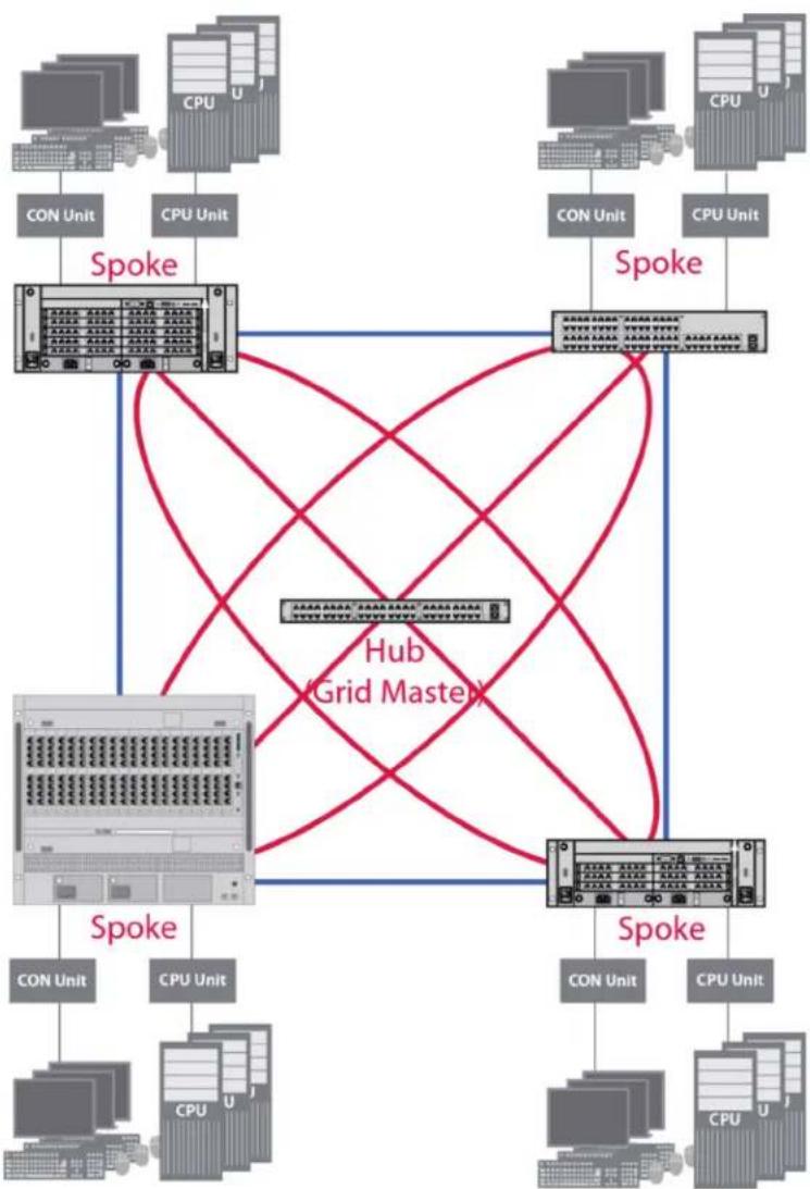
3.3.3 MATRIX GRID
You can use a matrix grid for applications where the required number of ports is not sufficient or important connections need to be made to several matrices to provide redundancy.
A matrix grid consists of one master matrix and at least one slave matrix. In its maximum configuration, it can consist of up to 16 matrices.
To build a matrix grid, the grid matrices are interconnected by "Grid Lines." In this case, the slave matrices can be connected directly to the master matrix or between themselves.
When arranging the grid lines, various grid setups can be realized, for example: a ring setup, a hub and spoke setup or a fully connected setup of matrices.
Grid lines can process signals bidirectional (Smart Connect). Per grid line, one KVM connection can be transmitted.
All switching operation will be exclusively performed through the Grid Master.
To configure the matrix grid, see see Section 4.15.
CHAPTER 3: INSTALLATION
NEED HELP?
LE AVE THE TECH TO US
LIVE 24/7
TECHNICAL
SUPPORT
1.8 7 7.87 7.2269
flowchart
graph TD
    subgraph Hosts
        A["CON Unit"] --> B["Spoke"]
        C["CPU Unit"] --> B
        D["Con Unit"] --> E["Spoke"]
        F["CPU Unit"] --> E
        G["Con Unit"] --> H["Spoke"]
        I["CPU Unit"] --> H
    end
    subgraph Grid Masters
        J["Hub (Grid Master)"] --> K["Spoke"]
        L["Spoke"] --> K
    end
    B --> E
    E --> H
    H --> I
    I --> J
    J --> K
    style Hosts fill:#f9f,stroke:#333
    style Grid Masters fill:#ccf,stroke:#333
FIGURE 3-3. MATRIX GRID INSTALLATION EXAMPLE
4.1 COMMAND MODE
The Compact KVM Matrix Switch includes a Command Mode that allows several functions to be controlled by keyboard commands during normal use.
To enter Command Mode, use a Hotkey sequence, and to exit Command Mode, press
NOTE: In Command Mode, normal keyboard and mouse operation will cease. Only selected keyboard commands are available. If there is no keyboard command executed within 10 seconds after activating Command Mode, it will be deactivated automatically.
The following table lists the keyboard commands to enter and to exit Command Mode and to change the Hotkey sequence.
TABLE 4-1. KEYBOARD COMMANDS
| FUNCTION KEYBOARD COMMAND | |
| Enter Command Mode (default) 2x(or Hotkey) | |
| Exit Command Mode | |
| Change Hotkey Sequence | Until 2011-30-09:+, |
NOTE:
2x
The Hotkey sequence to enter Command Mode can be changed. The following table lists the Hotkey Codes for the available key sequences:
TABLE 4-2. HOTKEY CODES AND KEY SEQUENCES
| HOTKEY CODE HOTKEY |
| 0 Freely selectable (from 2012-01-12 on) |
| 2 2x |
| 3 2x |
| 4 2x |
| 5 2x |
| 6 2x |
| 7 2x |
| 8 2x |
NOTE: In a combined KVM matrix / U-Switch configuration, choose different Hotkeys for the KVM matrix and the U-Switch.
CHAPTER 4: CONFIGURATION
SET FREELY SELECTABLE HOTKEY (EXAMPLE)
To set a freely selectable Hotkey (e.g. 2x
SET HOTKEY FOR DIRECT OSD ACCESS
Next to the Hotkey for standard functions, this Hotkey can be exclusively used for opening the OSD directly.
To select a Hotkey from the Hotkey table for a direct opening of the OSD, use the following keyboard sequence:
To select a freely selectable Hotkey (e.g. 2x
RESET HOTKEY
To set a Hotkey back to default settings of the extender, press the key combination within 5 seconds after switching on the CON Unit or plugging in a keyboard.
To delete the Hotkey for direct OSD access, use the following keyboard sequence:
,
4.2 CONTROL OPTIONS
The Compact KVM Matrix Switch contains an internal CPU that allows you to control all functions from any console without the need for an external CPU or media control.
You have the following options to access the Compact KVM Matrix Switch for configuration and operation:
- via OSD
- via Java Tool
- via serial interface
4.2.1 CONTROL VIA OSD

Via OSD (On-Screen-Display), you set the configuration of the Compact KVM Matrix Switch operating system. The settings of the Configuration menu are described below. All other menus are described in later chapters.
You have the following options to enter the OSD of the Compact KVM Matrix Switch:
- via keyboard connected to the CPU board
- via keyboard connected to a CON Unit of an extender
CHAPTER 4: CONFIGURATION
ENTERING OSD
- Start Command Mode with the Hotkey (see Section 4.1).
- Press
to open OSD. You will see a list of all available CPUs as a start menu. - Press
to enter the main menu.
NOTE: If the Enable CPU Selection option is enabled in the Configuration menu, the selection list for switching CPU devices will be opened initially. To skip this list, press the
LEAVING OSD
Press
The OSD will be closed without any further changes and the currently active CPU connection will be displayed.
MENU STRUCTURE

text_image
03000 CON 010123614 ESC:Login/Logout Menu Switch Status Configuration About ... Shift·ESC - Close SWITCH 01FIGURE 4-1. EXAMPLE VIEW
The general layout of the OSD is structured into three areas:
♦ Upper status area (topmost two text lines)
- Working area
♦ Lower status area (lowest two text lines)
CHAPTER 4: CONFIGURATION
NEED HELP?
LE AVE THE TECH TO US
LIVE 24/7
TECHNICAL
SUPPORT
1.8 7 7.87 7.2269
KEYBOARD CONTROL
You can select the following keyboard commands.
TABLE 4-3. KEYBOARD COMMANDS
| FUNCTION KEYBOARD COMMAND | |
| Left cursor - only within an input field or a switching screen | |
| Right cursor - only within an input field or a switching screen | |
| In input fields: Line up (with wrap around) | |
| In menus: Line up (without wrap around) | |
| In input fields: Line down (with wrap around) | |
| In menus: Line down (without wrap around) | |
| Previous page in menus with more than one page | |
| Next page in menus with more than one page | |
| Next input field | |
| Previous input field | + |
| Next option in selection fields | <-> |
| Previous option in selection fields | <-> |
| Switching in selection fields between two conditions, e. g. between ON / OFF or Y (Yes) / N (No) | |
| In menus with input fields: Save data | |
| In menus: Select menu item | |
| In menus with input fields: Cancel data input without saving | |
| In menus with selection fields: Go back to the superior menu | |
SORTING FUNCTION
Lists and tables in the Java Tool offer a sorting function for fast and smooth search.
The following sorting functions are available.
TABLE 4-4. SORTING FUNCTIONS
| FUNCTION | KEYBOARD COMMAND |
| Sort ID numbers in descending order by pressing the keyboard command once.Sort ID numbers in ascending order by pressing the keyboard command twice (ID). | |
| Sort ID names in descending order by pressing the keyboard command once.Sort ID names in ascending order by pressing the keyboard command twice (Name). | |
| Go to the next result in the list of results of the search field (Next). | |
| Go to the previous result in the list of results of the search field (Previous). | |
| Refresh the currently shown list (Refresh). | |
| Jump between the search field and the list of results (Find). |
CHAPTER 4: CONFIGURATION
NEED HELP?
LE AVE THE TECH TO US
LIVE 24/7
TECHNICAL
SUPPORT
1.8 7 7.87 7.2269
PASSWORD REQUEST
You have to login with administrator rights to be able to set configurations.

text_image
03000 CON 010123614 Login User Password Cancel Okay SWITCH 01FIGURE 4-2. LOGIN
Access to the configuration menu requires administrator rights. User login is mandatory.
TABLE 4-5. LOGIN
| FIELD INPUT |
| User admin |
| Password admin |
By pressing
For security reasons, please change the administrator password as soon as possible (see Section 4.4.1).
4.2.2 CONTROL VIA JAVA TOOL

REQUIREMENTS
If you want to use the Java Tool, you will need:
- Computer with an executable Java Tool and an installed Java Runtime Environment (JRE, version 1.7 or higher)
- Java Tool software
◆ Available network connection between the Java Tool and the matrix
NOTE: Contact your system administrator concerning JRE and network connection.
INSTALLATION OF THE JAVA TOOL
The Java Tool is available as a single executable program file that does not require a separate installation.
- Copy the tool after receiving the file to a directory on your computer.
NOTE: If you do not have a copy of the Java Tool, contact Black Box Technical Support at 877-877-2269 or info@blackbox.com.
COMPUTER CONNECTION TO THE MATRIX
For a direct connection between computer and matrix, a cross-wired network cable is required.
For a connection between computer and matrix via switch or hub, a parallel assembled network cable is required.
Do not use a network connection between Java Tool and the matrix that is primarily used for transmitting audio data.
- Connect the network cable to the RJ-45 ports of computer and CPU board of the matrix.
START OF THE JAVA TOOL
- Open the Java Tool by double-clicking on the program icon or press the
CONNECTION TO THE MATRIX
NOTE: At least FTP rights are required.
- Open the Java Tool.
- Select Matrix > Connect in the menu bar.
- Enter the IP address in the popup input field according to the network configuration of the Compact KVM Matrix Switch (see Section 4.2.3).
- Enter the user name and password for the Compact KVM Matrix Switch (see Section 4.4.1).
- Confirm your inputs with the OK button or reject with Cancel.
CHAPTER 4: CONFIGURATION
NEED HELP? LE AVE THE TECH TO US
LIVE 24/7 TECHNICAL SUPPORT
1.8 7 7.87 7.2269

text_image
Edit Device Entry Open... Save Reload Connect Disconned Activate Online Configuration Save Online Changes Download... Upload Monitoring Report Device Finder System Check Save Status Connect HostName / IP Address 192.168.106.217 Name admin Password ******** OK CancelFIGURE 4-3. CONNECT
NOTE: Up to twelve connections between the matrix and the Java Tool can be established at the same time due to a limitation of available sockets.
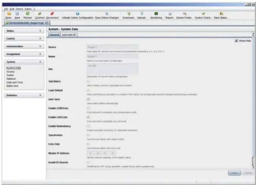
text_image
File Edit Device Express 2 Open... Save Forward Connected Download Activate Online Configuration Save Online Changes Downset... Upload... Monitoring Report... Device Finder... System Check... Save Status... 20150305063205_Report11.jpg System - System Data General Automatic ID Show Help Device Region 1 Host name for network environment (recommended characters, a.d., A.C., 9.4.1) Name Region 1 Name of current mesh configuration Info: 1.A11/20 Description of current mesh configuration Sub Matrix After Hotkey partition is cascaded environment Load Default When performing a port switch or a reset of the matrix, the configuration insert is Contact and will ensure activated. Auto Save Save matrix options automatically Enable COM Echo Extra all switch commands via communication units Enable LAN Echo Show auto switch commands via LAN ports Enable Redentary Excess automatic filtering for redentary indicators Specimenion Syncriconic matrix with master matrix Echo Only Specimenic matrix with active only Master IP Address Set the network address of the regular teams. Model ISO Boards Shallful at OPT during operation, create during matrix systems only Cancel CancelFIGURE 4-4. SYSTEM—SYSTEM DATA
CHAPTER 4: CONFIGURATION
NEED HELP?
LE AVE THE TECH TO US
LIVE 24/7
TECHNICAL
SUPPORT
1.8 7 7.87 7.2269
The menu structure of the Java Tool is subdivided into various sections:
- Menu bar (top line)
- Toolbar (second line)
Tab bar (third line)
◆ Task area (left menu section) - Working area (right menu section)
- Status bar (bottom line section)
OPERATING INSTRUCTIONS
The operation of the Java Tool is intuitive and corresponds to the user interface of common operating systems.
The Java Tool contains its own support function.
The integrated help texts in the working area of the Java Tool can be activated or deactivated by the checkbox in the upper right corner.
MOUSE CONTROL
You can select the following mouse commands.
TABLE 4-6. MOUSE COMMANDS
| FUNCTION MOUSE COMMAND |
| Menu selection, marking Left mouse button |
| Open function-specific selection menus Double-click left mouse button |
| Open context-specific selection menus Right mouse button |
KEYBOARD CONTROL
You can select the following keyboard commands.
TABLE 4-7. KEYBOARD COMMANDS
| FUNCTION MOUSE COMMAND | |
| Cursor to the left | |
| Cursor to the right | |
| Line up | |
| Line down | |
| Previous page in input or status menus with more than one page | |
| Next page in input or status menus with more than one page | |
| Next field in input menus | |
| Previous field in input menus | + |
CHAPTER 4: CONFIGURATION
NEED HELP?
LE AVE THE TECH TO US
LIVE 24/7
TECHNICAL
SUPPORT
1.8 7 7.87 7.2269
TABLE 4-7 (CONTINUED). KEYBOARD COMMANDS
| FUNCTION MOUSE COMMAND | |
| Switching in selection fields between two conditions (checkmark or not).Open already marked fields with editing or selecting possibility. | |
| In menus: Data savingMenu item selection | |
| Leave tablesJump from tables into the next field | + |
| Leave tablesJump from tables into the previous field | + + |
NOTE: Various functions within the menus in the menu bar can be executed with the provided keyboard commands
(e. g. press to execute Save) that are listed to the right of the respective menu item.
RELOAD OPTIONS
The information shown in the Java Tool can be reloaded in different ways.
- Via
on the keyboard used - Via Edit > Reload in the menu bar
- Via "Reload" Symbol in the symbol bar
CONTEXT FUNCTION
The Java Tool offers several context functions that support user-friendly and effective operation. The context functions are described in the respective chapters.
- To execute a context function, use the right mouse button on the corresponding field and select the desired function.
SORTING FUNCTION
Lists and tables in the Java Tool offer a sorting function for fast and smooth search.
- Ascending: Click left mouse button once on the header of the column to be sorted. The sort status is indicated by an arrow that points upwards.
- Descending: Click left mouse button once on the header of the column to be sorted. The sort is displayed by an arrow that points downwards.
- Cancel sort: Click left mouse button once or twice on the head of the sorted column. The arrow displayed disappears.
FILTER FUNCTION
Lists and tables in the Java Tool offer a filter function that allows a fast and smooth search.
- To activate a filter, use the right mouse button to click on the header of the column to be filtered and select Set Filter.
- Write the word or part of a word that has to be filtered into the header. The filter results are shown immediately.
- To delete a filter, use the right mouse button to click on the header of the column that has to be filtered and select Clear Filter.
NOTE: An active filter is indicated by an asterisk in the header.
CHAPTER 4: CONFIGURATION
NEED HELP? LE AVE THE TECH TO US
LIVE 24/7 TECHNICAL SUPPORT
1.8 7 7.87 7.2269
The filter function is based on the functional principle of common web search engines.
Configuration and system settings via Java Tool can be changed in offline mode without a direct connection between matrix and Java Tool.
To activate a matrix configuration, proceed as follows:
- Select File > Upload in the menu bar.
- Enter the IP address of the matrix (see Section 4.2.3) and the name and password of the user authorization and select the storage location of the new configuration (default or config01-08) in the Select Configuration menu.
- Select Matrix > Connect in the menu bar and enter the IP address of the matrix and the name and password for user authorization.
- Select Administration > Activate Configuration in the task area and select the storage location that has been selected above.
- Use the Activate button to open the selected configuration within the matrix.
The connection and the open tab will be closed and the matrix will be restarted.
NOTE During the activation of a configuration, the matrix is temporarily unavailable.
Configurations and system settings can be also edited via Java Tool in online mode with an active connection between matrix and Java Tool.

text_image
Edit - Set Device Elys 2 Green, Blue, Reload, Connect, Disconnect, Deadeable Online Configuration, Save Online Changes, Download, Upload, Monitoring, Report, Device Finder, System Check, Save Status 2019/05/08/1208_Report1.jsp Status Control Administration Assignment System System Data Access Switch Network Date and Time Matrix Grid Definition System - System Data General Automatic ID Device Region 1 Name Region 1 Info 141128 Description of current data's configuration Sub-Matrix Allow following synchronization calculated environment Load Default When performing a cold effect or a multipit of this matrix, the configuration stored in Default will be always activated Auto Save Basic matrix stable automatically Enable COM Echo Basic of switch commands via communication ports Enable LAR Echo Basic of switch commands via LAR ports Enable Redundancy Enable automatic switching by redundant senders Synchronization Synchronization matrix with header matrix Echo Only Synchronization matrix with echo only Master IP Address Set the network address of the header matrix Insolid IO Boards Show HelpFIGURE 4-5. SYSTEM—SYSTEM DATA
CHAPTER 4: CONFIGURATION
To edit a configuration in online mode, proceed as follows:
- Select the menu item Matrix > Activate Online Configuration Mode. This setting will also be shown in the lower part of the working area.
- Make any edits at the configuration and system settings and confirm them by pressing the Apply button. The changes will be applied immediately.
- To deactivate the online mode, select the menu item Matrix > Deactivate Online Configuration Mode in the menu bar.
On newer firmware, you will need to enable the Java Tool using the local OSD from a receiver by logging into the Configuration Menu as admin, and go to System options. You will then find a setting to allow Java communication. Save the settings and the Java tool will be able to work using the Online Configuration Mode.
OPTIONS MENU
The Java Tool can be adapted and customized by editing various default settings.
To activate or change the default settings, proceed as follows:
- Select Extras > Options in the menu bar. The Default Settings tab will open.
The following default settings parameters can be changed.
TABLE 4-8. DEFAULT SETTINGS PARAMETERS OPTIONS
| OPTION DESCRIPTION | |
| IP / Hostname Default IP address of the matrix required for connection | |
| User Default user name required for connection | |
| Configuration Directory Default directory for configuration files | |
| Firmware Directory Default directory for update files | |
| Status Directory Default directory for the firmware status | |
| Import / Export Directory | Default directory for import and export files |
| Presets Directory | Default directory for macro files |
To set various font sizes for the Java Tool, proceed as follows:
- Select Extras > Options in the menu bar.
- Open the Font tab.
- Select the desired font size (normal or large).
REPORT
The Java Tool is equipped with a report function that shows the current switching status and all relevant parts of the matrix configuration in a PDF file.
To create a report, proceed as follows:
- Select File > Report... in the menu bar. A selection assistant will be opened.
- Select contents that should be included in the report (Matrix View, EXT Units, CPU Devices, CON Devices and Users) and confirm with the Next > button.
- Select the preferred location for storage of the report and confirm with the Finish button.
The report will be created as a PDF file.
CHAPTER 4: CONFIGURATION
NEED HELP? LE AVE THE TECH TO US
LIVE 24/7 TECHNICAL SUPPORT
1.8 7 7.87 7.2269

text_image
Edit - Set Device Editor 2 Green...Save...Record...Connect...Connect...Activate Online Configuration Save Online Changes Download...Upload...Monitoring...Report...Device Finder...System Check...Save Status... 2019030083209_Regen11.cs Status Control Administration Assignment System Definition System - System Data General Automatic ID Device Name Info Sub Matrix Load Default Auto Save Enable COM Echo Enable LAW Echo Enable Hardware Synchronics Echo Only Master IP Address Insolid IO Boards Configurations Report? Steps 1. Define Content 2. Save Report Define Context ■ Status View ■ System ■ Assignment ■ EXT Units ■ CPU Devices ■ CON Devices ■ Access Control ■ Features ■ Macros ■ User ■ Access Control ■ Features ■ Macros ■ Select All Select All Show Help +/- when +/- when +/- when +/- when +/- when +/- when +/- when +/- when +/- when +/- when +/- when +/- when +/- when +/- when +/- when +/- when +/- when +/- when +/- when +/- when +/- when +/- when +/- when +/- when +/- when +/- where +/- where +/- where +/- where +/- where +/- where +/- where +/- where +/- where +/- where +/- where +/- where +/- where +/- where +/- where +/- where +/- where +/- where +/- where +/- where +/- where +/- where +/- where +/- where +/- where +/-where +/- where +/- where +/- where +/- where +/- where +/- where +/- where +/- where +/- where +/- where +/- where +/- where +/- where +/- where +/- where +/- where +/- where +/- where +/- where +/- where +/- where +/- where +/- where +/- where +/- caseFIGURE 4-6. REPORT
NOTE: The report function can be used in both online or offline mode of the Java Tool.
4.2.3 CONTROL VIA SERIAL INTERFACE

The Compact KVM Matrix Switch operating system offers various functions for operation via a serial interface. There are telegrams for switching single or all connections available, both unidirectional and bidirectional. In addition, there are telegrams for an overall definition of the total switching status and for saving and loading such switching states.
The Compact KVM Matrix Switch optionally provides an echo of all affected switching operations via a serial interface or a network interface. This aids continuous tracking of a matrix configuration and enables your own applications to be updated.
As an additional application, you can switch matrix clones in parallel as synchronized matrices (Stacking) via a serial network interface.
CHAPTER 4: CONFIGURATION
NEED HELP?
LE AVE THE TECH TO US
LIVE 24/7
TECHNICAL
SUPPORT
1.8 7 7.87 7.2269
4.3 ASSIGNMENT
The Compact KVM Matrix Switch offers the option of a console-specific or a CPU-specific assignment.
- Assign virtual CPUs to real CPUs.
- Assign real consoles to virtual consoles.
4.3.1 VIRTUAL CPU
You can assign virtual to real CPUs in this menu.
With this function, the effort of switching several consoles to the same CPU can be reduced. If several consoles are connected to a virtual CPU that is assigned to a real CPU, you only have to change the real CPU once and all consoles will receive the video signal of the new CPU.
You have the following options to access the menu:


OSD
- Select Assignments > Virtual CPU Devices in the main menu.
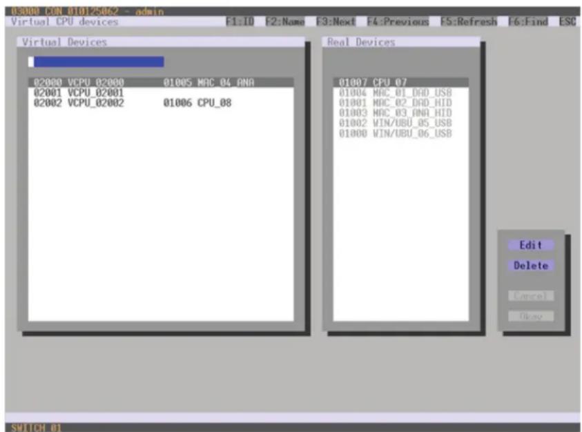
text_image
03000 CON 01012506.2 - admin Virtual CPU devices F1:ID F2:Name F3:Next F4:Previous F5:Refresh F6:Find ESC Virtual Devices 02000 VCPU_02000 01005 MAC_04_ANA 02001 VCPU_02001 02002 VCPU_02002 01006 CPU_08 Real Devices 01007 CPU_07 01004 MAC_01_DAD_USB 01001 MAC_02_DAD_HID 01003 MAC_03_ANA_HID 01002 WIN/UBU_05_USB 01000 WIN/UBU_06_USB Edit Delete Cancel Okay SWITCH 01FIGURE 4-7. VIRTUAL CPU DEVICES
CHAPTER 4: CONFIGURATION
NEED HELP? LE AVE THE TECH TO US
LIVE 24/7 TECHNICAL SUPPORT
1.8 7 7.87 7.2269
For an assignment, proceed as follows:
- Select the virtual CPU in the Virtual Devices list that has to be assigned to a real CPU.
- Press the Edit button.
- Select the CPU in the Real Devices list that has to be assigned to the selected virtual CPU.
- Press the Okay button to confirm the assignment.
The assignment will be made.
NOTE: Only one virtual CPU can be assigned to a real CPU.
JAVA TOOL
- Select Assignments > Virtual CPU Devices in the task area.
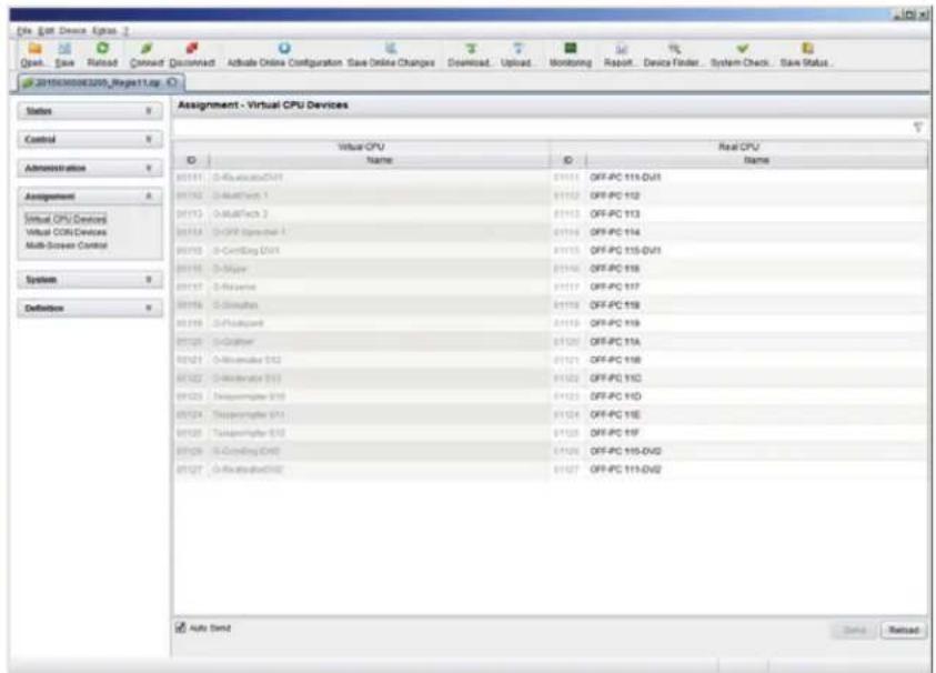
text_image
Assign - Virtual CPU Devices Status Control Administration Assignment Virtual CPU Devices Virtual CPU Devices Multi-Screen Control System Definition Virtual CPU Name Real CPU Name 01111 D-Revolution/DVI 01112 D-MathTrout 1 01113 D-MATTech 2 01114 D-CFF Expression 1 01115 D-ConfigDigi DVI 01116 D-Major 01117 D-Reserve 01118 D-Constellation 01119 D-Fieldguard 01120 D-Graphier 01121 D-Minematic Data 01122 D-Mindirector Data 01123 Transmembrane Data 01124 Transmembrane Data 01125 Transmembrane Data 01126 D-ConfigDigi Data 01127 D-ConfigDigi Data Auto Send Done RefreshFIGURE 4-8. VIRTUAL CPU DEVICES
For an assignment, proceed as follows:
- Select a virtual CPU in the Virtual CPU list.
- Double-click in the Real CPU column to display a list of all available real CPUs.
- Select a real CPU.
You can select the following buttons.
TABLE 4-9. BUTTONS
| BUTTON FUNCTION |
| Send Send assignments to the matrix |
| Reload Reload changes |
CHAPTER 4: CONFIGURATION
NOTE: When the Auto Send function in the left lower corner of the work area is ticked, switching operations will be completed immediately without user confirmation via the Send button.
The selection boxes in the Real CPU column contain a filter function for easy selection of a single CPU from a larger pool of CPUs (see Section 4.2.2).
The Java tool offers the option to switch directly from the Assignment menu to the Definition menu to check specific settings for the respective console or CPU.
- Use the right mouse button to select the respective console or CPU and select Open CON Device or Open CPU Device.
4.3.2 VIRTUAL CONSOLE
You can assign real consoles to virtual consoles in this menu.
This function reflects changes in permission made to virtual consoles onto real consoles.
Virtual consoles can be switched in the same way as real consoles. Real consoles that are assigned to a virtual console that is connected to a CPU will receive the video signal. The last-assigned console will also have control of the keyboard and mouse.
You have the following options to access the menu:

text_image
OSD JAVAOSD
- Select Assignments > Virtual CON Devices in the main menu.

text_image
03000 CON_010125492 - admin Virtual CON devices F1:10 F2:Name F3:Next F4:Previous F5:Refresh F6:Find ESC Real Devices 03006 CON_010128491 04000 VCON_04000 03000 CON_010125062 03002 CON_010125349 04000 VCON_04000 03001 CON_010125524 03004 CON_010129565 03005 CON_010129653 04001 VCON_04001 03003 CON_010148887 Virtual Devices 04000 VCON_04000 04001 VCON_04001 04002 VCON_04002 Edit Delete Copy Obay SUTCH 01FIGURE 4-9. VIRTUAL CON DEVICES
CHAPTER 4: CONFIGURATION
NEED HELP? LE AVE THE TECH TO US
LIVE 24/7 TECHNICAL SUPPORT
1.8 7 7.87 7.2269
For an assignment, proceed as follows:
- Select the real console in the Real Devices list that has to be assigned to a virtual CPU.
- Press the Edit button.
- Select the virtual console in the Virtual Devices list that has to be assigned to the selected real console.
- Press the Okay button to confirm the assignment. The assignment will be made.
NOTE: A virtual console can be assigned to more than one real console.
JAVA TOOL
- Select Assignments > Virtual CON Devices in the task area.
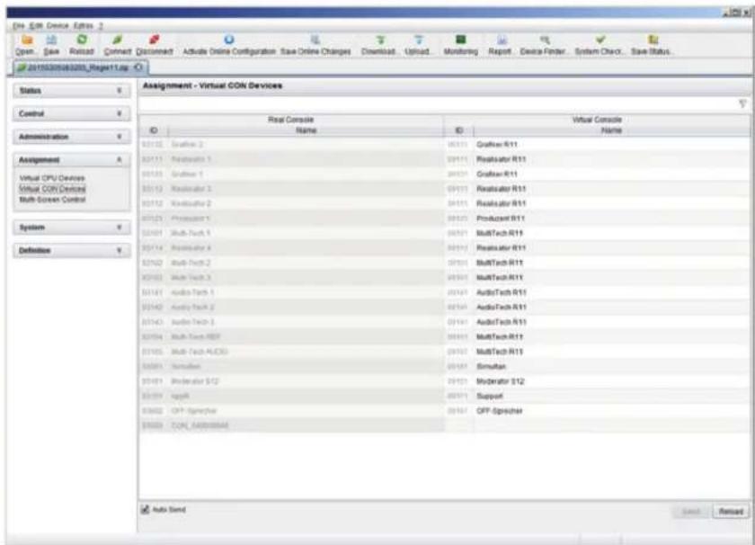
text_image
Assign - Virtual CON Devices Real Console Name Virtual Console Name 01012 Graffler 2 01013 Replinator 1 01014 Graffler 1 01015 Replinator 2 01016 Replinator 3 01017 Replinator 4 01018 Audio Tech 1 01019 Audio Tech 2 01020 Audio Tech 3 01021 Audio Tech 4 01022 Audio Tech 5 01023 Audio Tech 6 01024 Audio Tech 7 01025 Audio Tech 8 01026 Audio Tech 9 01027 Audio Tech 10 01028 Audio Tech 11 01029 Audio Tech 12 01030 Audio Tech 13 01031 Audio Tech 14 01032 Audio Tech 15 01033 Audio Tech 16 01034 Audio Tech 17 01035 Audio Tech 18 01036 Audio Tech 19 01037 Audio Tech 20 01038 Audio Tech 21 01039 Audio Tech 22 01040 Audio Tech 23 01041 Audio Tech 24 01042 Audio Tech 25 01043 Audio Tech 26 01044 Audio Tech 27 01045 Audio Tech 28 01046 Audio Tech 29 01047 Audio Tech 30 01048 Audio Tech 31 01049 Audio Tech 32 01050 Audio Tech 33 01051 Audio Tech 34 01052 Audio Tech 35 01053 Audio Tech 36 01054 Audio Tech 37 01055 Audio Tech 38 01056 Audio Tech 39 01057 Audio Tech 40 01058 Audio Tech 41 01059 Audio Tech 42 01060 Audio Tech 43 01061 Audio Tech 44 01062 Audio Tech 45 01063 Audio Tech 46 01064 Audio Tech 47 01065 Audio Tech 48 01066 Audio Tech 49 01067 Audio Tech 50 Auto SendFIGURE 4-10. VIRTUAL CON DEVICES
To place an assignment, proceed as follows:
- Select the required real console in the Real Console table.
- Double-click in the Virtual Console column to display a list of all available virtual consoles.
- Select the required virtual console.
You can select the following buttons:
TABLE 4-10. BUTTONS
| BUTTON FUNCTION |
| Send Send assignments to the matrix |
| Cancel Reject changes |
NOTE: When the Auto Send function in the lower left corner of the work area is ticked, switching operations will be completed immediately without user confirmation via the Send button.
CHAPTER 4: CONFIGURATION
NEED HELP?
LE AVE THE TECH TO US
LIVE 24/7
TECHNICAL
SUPPORT
1.8 7 7.87 7.2269
The selection boxes in the Virtual Console column contain a filter function for easy selection of a single CON from a larger pool of CON devices (see Chapter 4.2.2).
4.4 SYSTEM SETTINGS
You have the option to configure the system settings of the Compact KVM Matrix Switch.
- The configuration of the system settings can only be done by users with administrator rights.
4.4.1 SYSTEM DATA
The system configuration is set in this menu.
You have the following options to access the menu.


You can select the following settings.
TABLE 4-11. SYSTEM DATA SETTINGS
| FIELD SELECTION DESCRIPTION | ||
| Device Text | Enter the device name of the matrix (default: SWITCH_01) | |
| Name Text | Enter the name of the configuration that is used to save the current settings (default: Standard) | |
| Info Text | Additional text field to describe the configuration (default: Factory settings) | |
| Sub Matrix | activated | If the matrix is defined as a sub matrix in the OSD, the user will lose control. Control can be recovered by using the keyboard command,,<o>. The OSD for the matrix that has been defined as a sub matrix will be reopened. |
| deactivated | Function not active (default) | |
| Load Default | activated | Starting the matrix after a restart or a switch-on with the default configuration |
| deactivated | Starting the matrix after a restart or a switch-on with the last saved configuration (default). | |
| Auto Save | activated | Save the current configuration of the matrix in the flash memory periodically. NOTE: During the save operation, the matrix will not operate. Saving takes place every 600 seconds, as long as changes of the configuration or switching operations have been executed in the meantime. |
| deactivated | Function not active (default) | |
| FIELD SELECTION DESCRIPTION | ||
| Enable COM Echo | activated | Send all switching commands performed in the matrix as an echo via serial interface. NOTE: This function should be enabled when using a media control via serial interface. |
| deactivated Function not active (default) | ||
| Enable LAN Echo | activated | Send all switching commands performed in the matrix as an echo via LAN connection. NOTE: This function should be enabled when using a media control via LAN connection or when using stacking with two ore more matrices. |
| deactivated Function not active (default) | ||
| Enable Redundancy | activated | Automatically switch to the second link of a connected redundant CON Unit when losing the primary link of a CPU Unit (default). NOTE: This function will have to be activated for both matrices in a fully redundant setup. |
| deactivated Function not active | ||
| Synchronize | activated Synchronize the slave matrix to the switch status of the master matrix. | |
| deactivated Function not active (default) | ||
| Echo Only | activated | Synchronize the matrix according to the echo of a second matrix. NOTE: This is a bidirectional synchronization where both matrices have to be configured as Synchronize with the Master IP of the respective other matrix. |
| deactivated Function not active (default) | ||
| Master IP Address | Numerical value | Set the network address of the master matrix (default value: 000.000.000.000) |
| Invalid IO-Boards | activated | Keep I/O boards with incorrect or invalid firmware online in the matrix. NOTE: To keep an I/O board with wrong or damaged firmware online in the matrix, the maintenance mode of the matrix will be activated. |
| deactivated | Shut down I/O boards with incorrect or invalid firmware automatically (default). | |
| Hor. Mouse Speed 1/x | 1-9 | Adjustment of the horizontal mouse speed, 1 = slow, 9 = fast (default value: 4) |
| Ver. Mouse Speed 1/x | 1-9 | Adjustment of the vertical mouse speed, 1 = slow, 9 = fast (default value: 5) |
| Double Click Time | 100-800 | Adjustment of the time slot for a double-click (default value: 200 ms) |
| Keyboard layout | Region | Set the OSD keyboard layout according to the keyboard used (default: German (DE)) |
CHAPTER 4: CONFIGURATION
NEED HELP?
LE AVE THE TECH TO US
LIVE 24/7
TECHNICAL
SUPPORT
1.8 7 7.87 7.2269
OSD
- Select Configuration > System in the main menu.
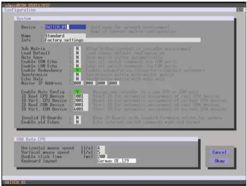
text_image
odniRCON 010167832 Configuration ESC System Device : SWITCH 01 Name : Standard Info : Factory settings Sub Matrix : N Load Default : N Auto Save : N Enable COM Echo : N Enable LAN Echo : N Enable Redundancy : V Synchronize : N Echo Only : N Master IP Address : 000 000 000 000 Enable Auto Config : V ID Real CPU Device : 1001 ID Virt. CPU Device : 2001 ID Real CON Device : 3001 ID Virt. CON Device : 4001 Invalid ID-Boards : N Enable old Echo : N USB Data CPU Horizontal mouse speed [1/x]: 4 Vertical mouse speed [1/x]: 5 Double click time [ms]: 200 Keyboard layout : German DE_129 Hunt uses for network environment Name of current matrix configuration Blue footprint useful in connected bus (random) Red always default configuration Show matrix utilit automatically Echo all switch commands via COM ports Echo all switch commands via LAN ports Enable automatic switching for redundant contenders Syncrptions matrix with master matrix. Syncrptions matrix with extra only Assign new extender to a new CPU or COM unit Start ID for automatic extension of real CPU devices Start ID for automatic extension of virtual CPU devices Start ID for automatic extension of real COM devices Start ID for automatic extension of virtual COM devices Keep ID-Boards with invalid firmware online for update Echo internal switch commands with old format Cancel Okay SWITCH 01FIGURE 4-11. CONFIGURATION—SYSTEM
You can select the following buttons.
TABLE 4-12. BUTTONS
| BUTTON FUNCTION |
| Cancel Reject changes |
| Save Save changes |
CHAPTER 4: CONFIGURATION
NEED HELP? LE AVE THE TECH TO US
LIVE 24/7 TECHNICAL SUPPORT
1.8 7 7.87 7.2269
JAVA TOOL
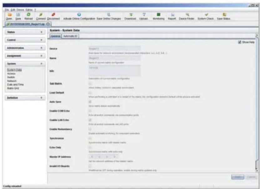
text_image
File Edit Device Errors Open Save Nexted Comment Deconstructed Active Online Configuration Save Online Changes Download Upload Monitoring Report Device Finder System Check Save Status 201503088888_Report1-up Status Control Administration Assignment Systems System Data Access Switch Network Data and Time Matrix Grid Definition System - System Data General Automatic ID Show Help Device Project 1 Post name for network environment (recommended characters, a.d., b.f., c.i.) Name: Project1 Name of current data configuration Info: Description of current-matrix configurations Sub Matrix Abit: Hotkey, connection is associated environment Load Default When performing a command on a command of the matrix, the configuration allows to (used within the active network) Auto Save Color name status supplementary Enable COM Echo Echo as useful commonly via communication ports Enable LRF Echo Echo as useful commonly on LRF ports Enable Redundancy Echo automatic switching for redundant packets Synchronization Synchronization matrix with master matrix Echo Only Synchronization matrix with master only Master IP Address Set the network address of the master matrix Insale VCI Boards ShelfUtilize the UST Operating operation, enable driving master updated only Config restructuredFIGURE 4-12. SYSTEM DATA
4.4.2 AUTOMATIC ID
Settings for automatic creation of CPU and CON Devices when a new extender unit is connected are made in this menu. You have the following options to access the menu.

text_image
OSD JAVACHAPTER 4: CONFIGURATION
NEED HELP? LE AVE THE TECH TO US
LIVE 24/7 TECHNICAL SUPPORT
1.8 7 7.87 7.2269
You can select the following settings.
TABLE 4-13. AUTOMATIC ID SETTINGS
| FIELD SELECTION DESCRIPTION | ||
| Enable Auto Config | activated | Automatic creation of a new CPU or CON Device if new extender units are connected (default) |
| deactivated Function not active | ||
| ID Real CPU Device | Numerical value | Initial value of the automatic ID for real CPUs (default value: 1000) |
| ID Virtual CPU Device | Numerical value | Initial value of the automatic ID for virtual CPUs (default value: 2000) |
| ID Real CON Device | Numerical value | Initial value of the automatic ID for real CONs (default value: 3000) |
| ID Virtual CON Device | Numerical value | Initial value of the automatic ID for virtual CONs (default value: 4000) |
OSD
- Select Configuration > System in the main menu.
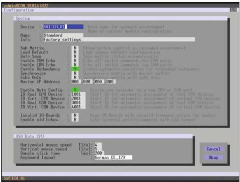
text_image
Device : SWITCH 01 Name : Standard Info : Factory settings Sub Matrix : N Load Default : N Auto Save : N Enable COM Echo : N Enable LAN Echo : N Enable Redundancy : V Synchronize : N Echo Only : N Master IP Address : 000 000 000 000 Enable Auto Config : V ID Real CPU Device : 1001 ID Virt. CPU Device : 2001 ID Real CON Device : 3001 ID Virt. CON Device : 4001 Invalid ID-Boards : N Enable old Echos : N Real case for network environment Name of current matrix configuration Allow buskey control in cascaded environment Load always default configuration Save matrix status automatically echo all micro commands via COM ports echo all switch commands via IOM ports Enable automatic switching for redundant encoders Synchronous matrix with master matrix Synchronous matrix with echo only Reset new extender to a new CPU or CON unit Start ID for automatic assignment of real CPU devices Start ID for automatic assignment of virtual CPU devices Start ID for automatic assignment of real COM devices Start ID for automatic assignment of virtual CON devices Keep ID-Boards with invalid firmware online for update. echo internal switch commands with old format OSD Data CPU Horizontal mouse speed 11/xl: 4 Vertical mouse speed 11/xl: 5 Double click time [ms]: 200 Keyboard layout : German DE.129 Cancel Okay SWITCH 01FIGURE 4-13. CONFIGURATION—SYSTEM
You can select the following buttons.
TABLE 4-14. BUTTONS
| BUTTON | FUNCTION |
| Cancel | Reject changes |
| Save | Save changes |
CHAPTER 4: CONFIGURATION
NEED HELP? LE AVE THE TECH TO US
LIVE 24/7 TECHNICAL SUPPORT
1.8 7 7.87 7.2269
JAVA TOOL
- Select the Automatic ID tab in System > System Data.
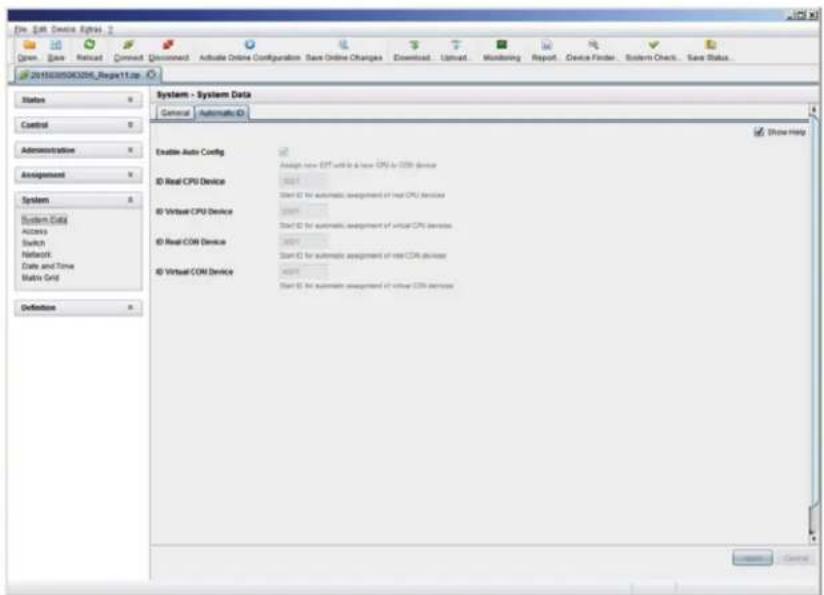
text_image
File Edit Device Express Draw Save Recall Correct Document Active Online Configuration Save Online Changes Download Update Monitoring Report Device Finder System Check Save Status... 20150305060208_Regp11.zip System - System Data General Automatic ID Enable Auto Config Assign new EMT will be a new CPU for CPU device ID Real CPU Device Start ID for automatic assignment of real CPU devices ID Virtual CPU Device Start ID for automatic assignment of virtual CPU devices ID Real COM Device Start ID for automatic assignment of real COM devices ID Virtual COM Device Start ID for automatic assignment of virtual COM devices Show Help Definition ControlFIGURE 4-14. SYSTEM-AUTOMATIC ID
CHAPTER 4: CONFIGURATION
NEED HELP?
LE AVE THE TECH TO US
LIVE 24/7
TECHNICAL
SUPPORT
1.8 7 7.87 7.2269
4.4.3 ACCESS
The access configuration is set in this menu.
You have the following options to access the menu.


You can select the following settings.
TABLE 4-15. ACCESS SETTINGS
| FIELD SELECTION DESCRIPTION | ||
| Force User Login | activated | The user has to login with a user name and a password once to enter the OSD. The user remains logged in until he explicitly logs out or an auto logout occurs. NOTE: When using the Force User Login function, console favorites and console macros still remain active. |
| deactivated Function not active (default) | ||
| Enable User ACL | activated | CPU access is restricted according to the permissions in the ACL (Access Control List).User login is required.Switching by keyboard Hotkeys requires a prior login. |
| deactivated Function not active (default) | ||
| Enable Console ACL | activated | CPU access is restricted according to the permissions in the respective Console ACL (Access Control List). No login required. |
| deactivated Function not active | ||
| Enable new User | activated Newly created users automatically receive access to all CPUs | |
| deactivated Function not active (default) | ||
| Enable new CON | activated Newly created CON Devices automatically receive access to all CPUs | |
| deactivated Function not active (default) | ||
| Auto Disconnect | activated | Upon opening the OSD, the console will be automatically disconnected from the current CPU. |
| deactivated Function not active (default) | ||
| OSD Timeout 0-999 seconds | Period of inactivity after which OSD will be closed automatically.Select 0 seconds for no timeout (default: 0 seconds) | |
| Auto Logout 0-999 minutes | Period of inactivity of a logged-in user at a console after which he will be automatically logged out. There may be a disconnect because of the logout, depending on the defined rights in each CON and user ACL.Select 0 minutes for an automatic user logout when leaving OSD.Using the setting -1 allows the user to be logged in permanently, until a manual logout is executed.The timer is not active as long as the OSD is open (default: 0 minutes) | |
CHAPTER 4: CONFIGURATION
NEED HELP?
LE AVE THE TECH TO US
LIVE 24/7
TECHNICAL
SUPPORT
1.8 7 7.87 7.2269
OSD
- Select Configuration > Access in the main menu.
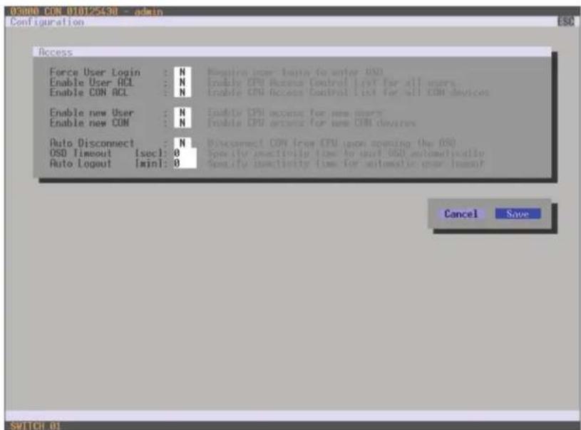
text_image
OSADO CON 010125438 - admin Configuration ESC Access Force User Login : N Enable User ACL : N Enable CON ACL : N Enable new User : N Enable new CON : N Auto Disconnect : N OSD Timeout [sec]: 0 Auto Logout [min]: 0 Require user login for any OSU Enable CPU Access Control List for all users Enable CPU Access Control List for all COM devices Enable new User : N Enable new CON : N Enable new CPU access for new user Enable new CON access for new COM devices Disconnect CON free CPU upon opening (the OS) Specify inactivity time to unit OSU automatically Specify inactivity time for automatic gear timeout Cancel Save SUTCH 01FIGURE 4-15. CONFIGURATION—ACCESS
You can select the following buttons.
TABLE 4-16. BUTTONS
| BUTTON FUNCTION |
| Cancel Reject changes |
| Save Save changes |
CHAPTER 4: CONFIGURATION
NEED HELP? LE AVE THE TECH TO US
LIVE 24/7 TECHNICAL SUPPORT
1.8 7 7.87 7.2269
JAVA TOOL
- Select System > Access in the task area.
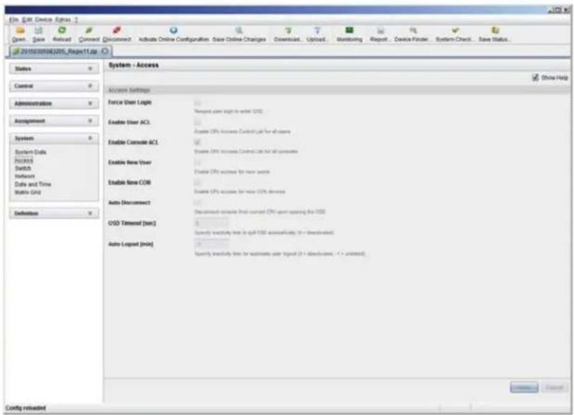
text_image
File Edit Device Extras Open... Save Reload Connect Disconnect Activate Online Configuration Save Online Changes Download... Upload... Monitoring Report... Device Finish System Check... Save Status... 2018030963205_Report11.sp Status Control Administration Assignment System System Data Process Switch Network Date and Time Matrix Grid Definition System - Access Access Settings Force User Logis Enable User ACL Enable Console ACL Enable New User Enable New COB Auto Document OISD Terminal (sec) Auto Logset (min) Show Help Remove Cancel Form: User logo Reagent: user logit in order: OIS Enable CIPs: Access Control List for all users Enable CIPs: Access Control List for all users Enable CIPs: Access Control List for all users Enable CIPs: Access Control List for all users Enable CIPs: Access Control List for all users Enable CIPs: Access Control List for all users Enable CIPs: Access Control List for all users Enable CIPs: Access Control List for all users OK/Cancel Config returnedFIGURE 4-16. SYSTEM-ACCESS
4.4.4 SWITCH
The configuration of the switching parameters is set in this menu.
You have the following options to access the menu.


You can select the following settings.
CHAPTER 4: CONFIGURATION
TABLE 4-17. SWITCH SETTINGS
| FIELD SELECTION DESCRIPTION | ||
| Video Sharing | activated | The user can switch to any CPU as an observer, including ones that are already assigned to another user (observer is without keyboard/mouse access).NOTE: Switch with thekey, not thekey.The operator will not be informed if further users connect as an observer to the CPU that is connected to his console. |
| deactivated Function not active (default) | ||
| Force Connect | activated | The user can connect to every single CPU as an operator, including ones that are related to another user.NOTE: The previous user is set to video-only status.To share K/M control, Force Connect has to be activated. |
| deactivated Function not active (default) | ||
| Force Disconnect | activated | Extension of Force Connect: If the user connects as an operator to a CPU already related to another user, the previous user will be disconnected.NOTE: To share K/M control Force Disconnect has to be deactivated. |
| deactivated Function not active (default) | ||
| CPU Auto Connect | activated | If a console is not connected to a CPU, you can establish an automatic connection to the next available CPU by pressing any key or mouse button. |
| deactivated Function not active (default) | ||
| CPU Timeout 0-999 minutes | Period of inactivity after which a console will be automatically disconnected from its current CPU (default value: 0 minutes) | |
| Keyboard Connect | activated Activate request of K/M control by keyboard event (key will be lost) | |
| deactivated Function not active (default) | ||
| Mouse Connect | activated Activate request of K/M control by mouse event | |
| deactivated Function not active (default) | ||
| Release Time 0-999 seconds | Period of inactivity of a connected console after which K/M control can be requested by other consoles connected to the CPU.NOTE: Set '0" for an immediate transfer in real-time.Only one console can have keyboard and mouse control at the same time.The other consoles that are connected to the same CPU have a video only status (default value: 10 seconds) | |
NOTE: If the Keyboard Connect and/or Mouse Connect options are activated, the Release Time condition will have to be met until a new user will gain control.
CHAPTER 4: CONFIGURATION
NEED HELP?
LE AVE THE TECH TO US
LIVE 24/7
TECHNICAL
SUPPORT
1.8 7 7.87 7.2269
OSD
- Select Configuration > Switch in the main menu.

text_image
ES3000 CPU 010123614 -- admin Configuration ESC Switch Enable Video Sharing : N Force Connect : N Force Disconnect : N CPU Auto Connect : N CPU Timeout [min] : 0 Keyboard Connect : N Mouse Connect : N Release Time [sec] : 10 Allow a broad video access to CPU Connect full CPU access to CPU, other commands return video Induces full CPU access to CPU, disconnection other commands. Connect to next available CPU, requires keyboard or write Specify inactivity time at currently connected CPU after which CPU will be disconnected automatically. Enable CPU control requests by keyboard actively Enable CPU control requests by mouse actively. Specify inactivity time to accept CPU control requests from other commands Cancel Save SWITCH 01FIGURE 4-17. CONFIGURATION-SWITCH
You can select the following buttons.
TABLE 4-18. BUTTONS
| BUTTON FUNCTION |
| Cancel Reject changes |
| Save Save changes |
CHAPTER 4: CONFIGURATION
NEED HELP?
LE AVE THE TECH TO US
LIVE 24/7
TECHNICAL
SUPPORT
1.8 7 7.87 7.2269
JAVA TOOL
- Select System > Switch in the task area.

text_image
File Edit Device Options 2 Open Save Review Connect Discount Activate Online Configuration Save Online Changes Download Upload Monitoring Report Device Finder System Check Save Status JF201935080000_Regpct1.exe Status Control Administration Assignment System System-Data Access Switch Referral Data and Time Mobile Grid Definition System - Switch Switch Settings Enable Video Sharing Force Connect Force Disconnect CPU Auto Connect CPU Termostat [net] Keyboard Connect Mouse Connect Release Time [sec] Show Help Enable Video Sharing Force Connect Force Disconnect CPU Auto Connect CPU Termostat [net] Specify explicitly format at currently connected CPG after which CPG will be disconnected automatically (I) or deactivated Enable CPG valid request by username activity Enable CPG valid request by mouse activity Specify Activity free to access CPG valid request from another mouseFIGURE 4-18. SYSTEM-SWITCH
CHAPTER 4: CONFIGURATION
4.4.5 NETWORK
The network configuration is set in this menu.
You have the following options to access the menu.


You can select the following settings.
TABLE 4-19. NETWORK SETTINGS
| FIELD SELECTION DESCRIPTION | ||
| DHCP | activated | The network settings are automatically supplied by a DNS serverNOTE: If DHCP is activated and there is no physical network connection available, the boot times might increase. |
| deactivated Function not active (default) | ||
| IP address | Byte | Input of the IP address, if DHCP is not active (default: 192.168.100.99) |
| Subnet Mask Byte | Input of the subnet mask in the form "255.255.255.0" if DHCP is not active (default: 255.255.255.0) | |
| Gateway Byte Input of the subnet mask in the form "192.168.1.1" if DHCP is not active | ||
| API Service | activated | LAN interface at the Compact KVM Matrix Switch activated for access via Java tool (API service port 5555) |
| deactivated Function not active | ||
| FTP Server | activated | FTP server for transmission of configuration files activated |
| deactivated Function not active | ||
| Syslog #1/#2 | activated | Syslog server for status request is active |
| deactivated Function not active (default) | ||
| Syslog Server #1/#2 | Byte | Input of the IP address of the Syslog servers in the form "192.168.1.1" and of the Syslog port (default: 514) |
| LDAP | activated | LDAP for the request of information from a user administration is active |
| deactivated Function not active (default) | ||
| LDAP Server | Byte | Input of the IP address for the LDAP-Servers in the form "192.168.1.1" and the LDAP port (Default: 389) |
| LDAP Base DN | Text | Input of the LDAP Base DN according to the existing structure of the user directory |
| Trace | DEB | Activate debug messages in Trace (default: NO)NOTE: The debug messages are exclusively for matrix diagnostics. They only should be activated after consultation with the manufacturer. Otherwise, increased data traffic might limit the performance of the CPU board. |
| INF | Activate information messages in Trace (default: NO) | |
CHAPTER 4: CONFIGURATION
NEED HELP?
LE AVE THE TECH TO US
LIVE 24/7
TECHNICAL
SUPPORT
1.8 7 7.87 7.2269
TABLE 4-19 (CONTINUED). NETWORK SETTINGS
| FIELD SELECTION DESCRIPTION | ||
| Trace (continued) | NOT | Activate notification messages in Trace (default: YES) |
| WAR | Activate warning messages in Trace (default: YES) | |
| ERR | Activate error messages in Trace (default: YES) | |
| Syslog #1/#2 | DEB | Activate debug messages in Syslog (default: NO)NOTE: The debug messages are exclusively for matrix diagnostics. They only should be activated after consultation with the manufacturer. Otherwise, increased data traffic might limit the performance of the CPU board. |
| INF | Activate information messages in Syslog (default: NO) | |
| NOT | Activate notification messages in Syslog (default: YES) | |
| WAR | Activate warning messages in Syslog (default: YES) | |
| ERR | Activate error messages in Syslog (default: YES) | |
NOTE: Activate the modified network parameters by restarting the matrix.
CAUTION: Consult your system administrator before modifying the network parameters. Otherwise, unexpected results and failures can occur in combination with the network.
CHAPTER 4: CONFIGURATION
NEED HELP?
LE AVE THE TECH TO US
LIVE 24/7
TECHNICAL
SUPPORT
1.8 7 7.87 7.2269
OSD
- Select Configuration > Network in the main menu.

text_image
odainPCON 010167832 Configuration ESC Network Interface DHCP : Y Enable configuration of network parameters via DHCP server IP Address : 192 168 100 099 Subnet Mask : 255 255 255 000 Gateway : 000 000 000 000 Network Services API Service : Y Enable API Service port (USB) FTP Server : Y Enable FTP Server for configuration file transfers Syslog #1: N Enable Syslog Server #1 Syslog Server #1: 000 000 000 000 514 Syslog #2: N Enable Syslog Server #2 Syslog Server #2: 000 000 000 000 514 LOOP : N Enable authentication with Active Directory Server LOOP Server : 000 000 000 000 389 LOOP Base DN : Log Levels Trace : DEB N INF N NOT V WAR V ERR V Syslog #1: DEB N INF N NOT V WAR V ERR V Syslog #2: DEB N INF N NOT V WAR V ERR V Cancel Okay SWITCH-01FIGURE 4-19. CONFIGURATION-NETWORK
You can select the following buttons.
TABLE 4-20. BUTTONS
| BUTTON FUNCTION |
| Cancel Reject changes |
| Save Save changes |
CHAPTER 4: CONFIGURATION
NEED HELP? LE AVE THE TECH TO US
LIVE 24/7 TECHNICAL SUPPORT
1.8 7 7.87 7.2269
RELEASE OF NETWORK PORTS
The following ports are used by the matrix depending on the configuration and have to be released at the security gateway, if necessary. The ports only will have to be released if you want to use the respective function.
TABLE 4-21. NETWORK PORTS
| FUNCTION PORT | |
| FTP 21 | |
| DNS 53 | |
| SNTP 123 | |
| SNMP 161/162 | |
| LDAP 389 | |
| Syslog 514 | |
| API 5555 | |
| Broadcast | 5556 |
| Matrix-Grid | 5557 |
JAVA TOOL
- Select System > Network in the task area.
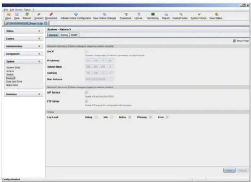
text_image
File Edit Device System Open Save Network Connect Document Activate Online Configuration Save Online Changes Download Upload Monitoring Report Device Finder System Check Save Status 2010/09/2010_Report13a Status Control Administration Assignment System System Data Address Switch Database Data and Time Matrix Grid Definition System - Network General Ending SNMP Show Help Network Interface (Online change, replace a matrix element) DHCP IP Address System configuration of network parameters on DHCP server- Submit Mask 2011.2011.2011.2011.2011.2011.2011.2011.2011.2011.2011.2011.2011.2011.2011.2011.2011.2011.2011.2011.2011 Gateway Mac Address 2011.2011.2011.2011.2011.2011.2011.2011.2011.2011.2011.2011.2011.2011.2011.2011.2011.2011.2011.201 Network Services (Online change, replace a matrix element) API Service Update API service after 2005 FTP Server Update FTP service for configuration to switches Access Log Level Debug Info Notice Warning Error Cancel Config reloadedFIGURE 4-20. SYSTEM-NETWORK
CHAPTER 4: CONFIGURATION
NEED HELP? LE AVE THE TECH TO US
LIVE 24/7 TECHNICAL SUPPORT
1.8 7 7.87 7.2269
4.4.6 DATE AND TIME
Date and Time are set in this menu, based on Simple Network Time Protocol (SNTP).
You have the following options to access the menu.


You can select the following settings.
TABLE 4-22. DATE AND TIME SETTINGS
| FIELD SELECTION DESCRIPTION | ||
| SNTP Client | activated Enable network time server synchronization | |
| deactivated Function not active (default) | ||
| SNTP Server | Byte | Input of the SNTP server IP address (default: 000.000.000.000) |
| Time Zone | Region | Set your specific time zone |
| Month 1-12 | Enter month | |
| Date | 1-31 | Enter date |
| Year | 1-99 | Enter year |
| Day | 1-7 Enter day of week | |
| Hours | 0-23 | Enter hour |
| Minutes | 0-59 | Enter minutes |
| Seconds | 0-59 | Enter seconds |
NOTE: This is date format according to the English notation.
CHAPTER 4: CONFIGURATION
NEED HELP? LE AVE THE TECH TO US
LIVE 24/7 TECHNICAL SUPPORT
1.8 7 7.87 7.2269
OSD
- Select Configuration > Date + Time in the main menu.

text_image
admin@CON_010125349 Multi-Screen Control ESC Arrangement * Switching Screens : 1 x 4 Use rows with four screens or two rows with two screens each Manual : N Reduce switching to manual switching with breakups Disable automatic switching with mouse for millibond PSIs Screen #1 CON_010125349 Enabled : V Control : N Owner : shared Frame : 0 sec Screen #2 screen not available Enabled : H Control : H Owner : Frame : sec Screen #3 screen not available Enabled : H Control : H Owner : Frame : sec Screen #4 screen not available Enabled : H Control : H Owner : Frame : sec Cancel Okay SWITCH #1FIGURE 4-21. CONFIGURATION-DATE + TIME
To configure a time server, follow these steps:
- Set the SNTP Client option to Y (Yes).
- Enter the IP address of your SNTP server in the SNTP Server field.
- Select your time zone in the Time Zone field.
- Press the Okay button to confirm your settings.
- Restart the matrix. The system time will be now provided by the SNTP server.
To set the real time clock without using SNTP, follow these steps:
- Set the current date in the Date field.
- Set the current Day in the Day field.
- Set the current time in the Time field.
- Press the RTC button to confirm your settings.
CHAPTER 4: CONFIGURATION
NEED HELP? LE AVE THE TECH TO US
LIVE 24/7 TECHNICAL SUPPORT
1.8 7 7.87 7.2269
JAVA TOOL
- Select System > Date + Time in the main menu.
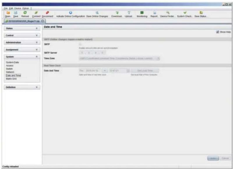
text_image
Date & Time SOTP (online changes requests a matching request) SOTP SOTP Server Time Zone Spread Time Clock Date And Time Data and time of next time value Set based time of risk components Status Control Administration Assignment System System Data Access Switch Networks Data and Time Matrix Grid Definition Show Help Show Time Show Time Show Time Show Time Show Time Show Time Show Time Show Time Show Time Show Time Show Time Show Time Show Time Show Time Show Time Show Time Show Time Show Time Show Time Show Time Show Time Show Time Show Time Show Time Show Time Show Time Show Time Show Time Show Time Show Time Show Time Show Time Show Time Show TimeFIGURE 4-22. CONFIGURATION-DATE + TIME
To configure a time server, follow these steps:
- Enable SNTP option.
- Enter the IP address of your SNTP server in the SNTP Server field.
- Select your time zone in the Time Zone field.
- Press the Apply button to confirm your settings.
- Restart the matrix. The system time will be now provided by the SNTP server.
To set the real time clock without using SNTP, follow these steps:
- Set the current date in the Date and Time field.
- Set the current time in the Day and Time field.
- Press the Apply button to set the system time.
- Option: If you want to receive the time from your currently used computer, press the Get Local Time button.
CHAPTER 4: CONFIGURATION
4.5 USER SETTINGS
You have the option to configure the following user settings.
4.5.1 USER
New users and their user settings and permissions are set in this menu.
You have the following options to access the menu.


You can select the following settings.
TABLE 4-23. USER SETTINGS
| FIELD SELECTION DESCRIPTION | ||
| Name Text User name (case-sensitive) | ||
| Password Text User password (case-sensitive) | ||
| Repeat Password Text Repeat user password (case-sensitive) | ||
| FTP | activated | Access permission via FTP. This setting is necessary for file access from the Java tool or any web browser. |
| desactivated Function not active (default). | ||
| Power User | activated | User has user rightsPermission to switch consoles to CPUs in Extended Switching according to the CON or User ACL |
| desactivated Function not active | ||
| Super User | activated | Permission to switch any console to any CPU in Extended Switching. |
| desactivated Function not active | ||
| Administrator | activated | Permission for system configuration and all switching operationsUser has administrator rightsThis setting is required for an online connection with the Java tool |
| desactivated Function not active | ||
| LDAP User | activated | Permission to login via domain user |
| desactivated Function not active | ||
CHAPTER 4: CONFIGURATION
NEED HELP?
LE AVE THE TECH TO US
LIVE 24/7
TECHNICAL
SUPPORT
1.8 7 7.87 7.2269
OSD
- Select Configuration > User in the main menu.

text_image
admin@RCON_018167832 Configuration F1:10 F2:Name F3:Next F4:Previous FS:Refresh F5:Find ESC User List ID : 1 Login Name : admin Full Name : Password : ****** Repeat Password : ****** Administrator : V HTTP Access : V Super User : V FTP Access : V Power User : V Telnet Access : V LOOP User : N CPU Access Control List Full access 01002 CPU_010135668 01003 CPU_010207794 01001 CPU_016090185 01004 CPU_040011492 Video access No access New Edit Enter a name to find an item SWITCH_01FIGURE 4-23. CONFIGURATION—USER
You can select the following buttons.
TABLE 4-24. BUTTONS
| BUTTON FUNCTION |
| New Create a new user |
| Edit Edit an existing user |
| Delete Delete an existing user |
| Cancel Reject changes |
| Save Save changes |
CHAPTER 4: CONFIGURATION
NEED HELP? LE AVE THE TECH TO US
LIVE 24/7 TECHNICAL SUPPORT
1.8 7 7.87 7.2269
JAVA TOOL
- Select Definition > User in the task area.
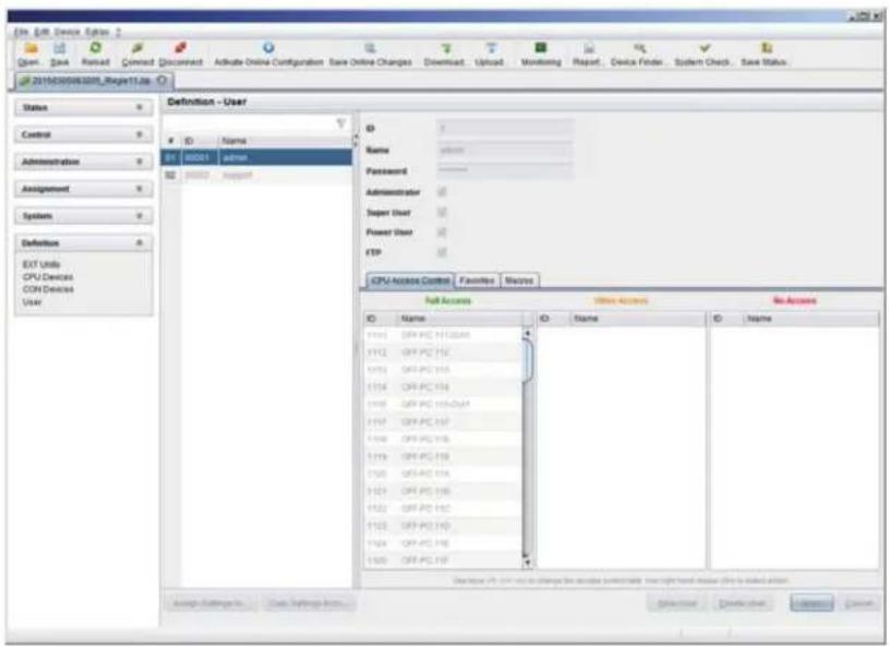
text_image
File Edit Device Options 2 Open Save Next Connect Document Activate Online Configuration Base Online Changes Download Upload Monitoring Report Device Finder System Check Save Status 201503056208_RegPTLIs Status Control Administration Assignment Systems Definition EXIT Units CPU Devices CON Devices User Definition - User ID Name S1 00001 user S2 00002 support Name Password Administrator Super User Power User FTP CPU NAME CO/THE Favorites Features No Access Full Access Name Name Name Description: Off User to change the active partitioning tool right touch user code is enabled action Assign Settings to Create Settings from Browse Create View InsertFIGURE 4-24. DEFINITION—USER
You can select the following buttons.
TABLE 4-25. BUTTONS
| BUTTON FUNCTION |
| New Open a new user configuration |
| Delete Delete an existing user |
| Apply Create a new user account |
| Cancel Reject changes |
To configure user access rights for CPUs, follow these steps.
-
Select a user in the User list.
-
Click the right mouse button once on a CPU in one of the respective access lists (Full Access, Video Access and No Access). Two lists for selection will appear in which you can move the respective CPU and change the access rights.
-
Confirm the configuration with the Apply button.
To create a new user, follow these steps.
- Press the New button.
- Select a template of an existing user if applicable (Choose template).
- Press the OK button.
CHAPTER 4: CONFIGURATION
NEED HELP?
LE AVE THE TECH TO US
LIVE 24/7
TECHNICAL
SUPPORT
1.8 7 7.87 7.2269
- Set a user name.
- Set a password.
- Set general access permissions.
- Set user permissions for CPU access (paste function).
- Set user favorites for OSD access.
- Press the Apply button to save the new user settings.
You can select the following keyboard commands.
TABLE 4-26. KEYBOARD COMMANDS
| FUNCTION KEYBOARD COMMAND |
| Add CPU to Full Access list |
| Add CPU to Video Access list |
| Add CPU to No Access list |
4.5.2 FAVORITE LIST USERS
Individual favorite lists of CPUs that will be switched frequently can be created for different users in this menu. A favorite list can contain up to 16 different CPUs.
The switching of the favorites is done via hotkey using the keyboard (see Section 5.1.1).
You have the following options to access the menu.


CHAPTER 4: CONFIGURATION
NEED HELP? LE AVE THE TECH TO US
LIVE 24/7 TECHNICAL SUPPORT
1.8 7 7.87 7.2269
OSD
- Select Assignments > User Favorites in the main menu.
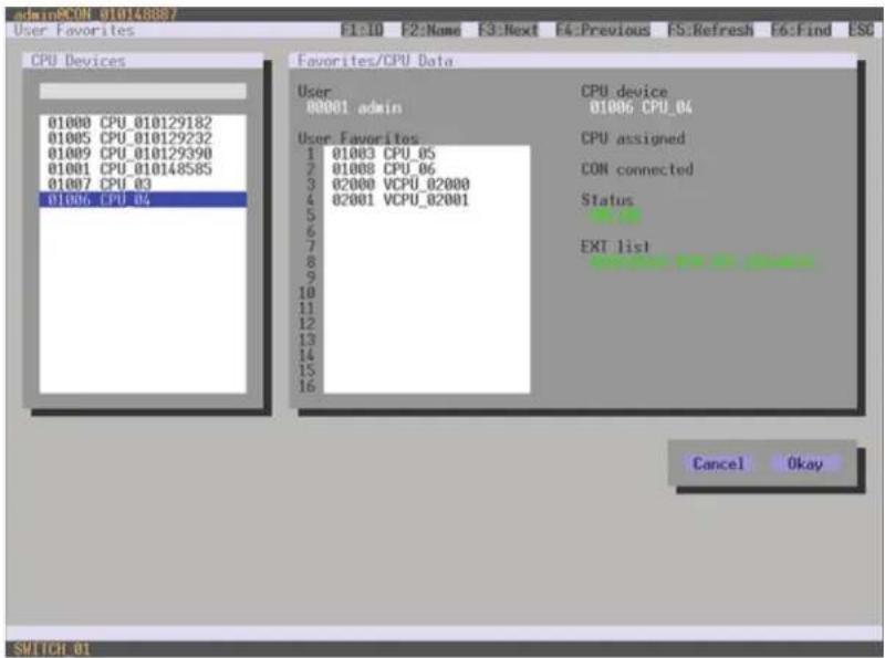
text_image
admin@CON_01014808/ User Favorites F1:10 F2:Name F3:Next F4:Previous FS:Refresh F5:Find ESC CPU Devices 01000 CPU_010129182 01005 CPU_010129232 01009 CPU_010129390 01001 CPU_010148585 01007 CPU_03 01006 CPU_04 Favorites/CPU Data User 00001 admin CPU device 01006 CPU_04 User Favorites 1 01003 CPU_05 2 01008 CPU_06 3 02000 VCPU_02000 4 02001 VCPU_02001 5 6 7 8 9 10 11 12 13 14 15 16 CPU assigned CON connected Status EXT list Cancel Okay SWITCH 01FIGURE 4-25. ASSIGNMENTS—USER FAVORITES
To create a favorite list for your user, proceed as follows:
- Select a CPU to be moved to the favorite list on the CPU Devices list. Press to move a CPU Device to the favorite list. Press
to remove a CPU. - The order of the CPU Devices within the favorite list can be changed by pressing <+> and <->.
- Press the Save button to save the settings.
CHAPTER 4: CONFIGURATION
JAVA TOOL
Select the respective user in the working area of the User menu for the favorite list and open the Favorites tab.
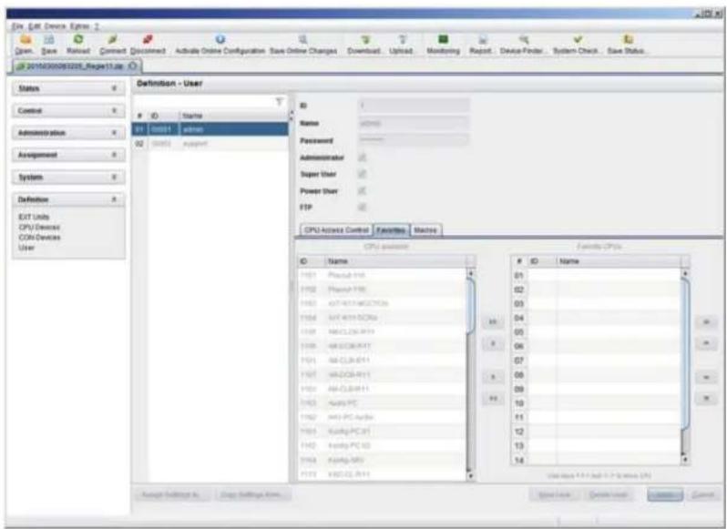
text_image
File Edit Devices Options Open, Save, Reload, Connect, Disconnect, Active Online Configuration, Save Online Changes, Download, Upload, Monitoring, Report, Device Finder, System Check, Save Status... 2016430060205_RegPage11.de Status Control Administration Assignment System Definition EQT Units CPU/Device CON-Devices User Definition - UserStart
01 00001 00002 02 00001 support ID Name Password Administrator Super User Power User FTP CPU Access Control Favorites Machine CPU access ID Name 01 02 03 04 05 06 07 08 09 10 11 12 13 14 Save Settings As Copy Settings Arm Save Value Create User Customize CancelFIGURE 4-26. DEFINITION-USER
To create a favorite list for any user, proceed as follows:
- Select the CPUs in the CPU available list that should be added to the favorite list (CPU assigned). By pressing the
at the same time, more than one CPU Device can be marked. - Press the > button to move the marked CPU Devices to the favorite list. If you press the >> button, the first eight CPU Devices from the CPU available list will be moved to the favorite list (CPU assigned).
- The order of marked CPU Devices within the favorite list can be changed by pressing <+> and <->.
- To remove marked CPU Devices from the favorite list, press the < button. If you press the << button, all CPU Devices will be removed from the favorite list.
4.5.3 USER MACROS
In this menu, macro commands for switching, disconnection or user administration can be created. Macro commands are created for each user separately.
A macro can execute up to 16 switching commands successively.
The execution of the macros is done via hotkey and the
To execute user macros, the user has to be logged in to the matrix.
CHAPTER 4: CONFIGURATION
NEED HELP? LE AVE THE TECH TO US
LIVE 24/7 TECHNICAL SUPPORT
1.8 7 7.87 7.2269
You can select the following settings.
TABLE 4-27. USER MACROS SETTINGS
| FIELD SELECTION DESCRIPTION | ||
| Function (01-16) | Connect(P1=CON, P2=CPU) | Set bidirectional connection from console P1 to CPU P2 |
| Connect Video(P1=CON, P2=CPU) | Set video connection from console P1 to CPU P2 | |
| Disconnect (P1=CON) Disconnect console P1 | ||
| Logout User Logout current user | ||
| Set Real CPU(P1=VCPU, P2=RCPU) | Assign a virtual CPU to a real CPU | |
| Set Virtual CON(P1=RCON, P2=VCON) | Assign a real console to a virtual console | |
| Push (P1=CON) | The user's KVM connection is forwarded to console P1 and is changed to a video only connection. | |
| Push Video (P1=CON) | The video signal of the current connection (KVM or video only) is forwarded to console P1. The user's connection remains unchanged (KVM or video only). | |
| Get (P1=CON) | The user's console gets a KVM connection to the CPU that is currently connected to console P1. The connection of console P1 is changed into a video only connection. | |
| Get Video (P1=CON) | The user's console gets a video only connection to the CPU that is currently connected to console P1. The connection of console P1 remains unchanged (KVM or video only). | |
| Login User console P2 Login a certain user P1 at console P2 | ||
| P1 CON or CPU Device Name of CON or CPU Device | ||
| P2 CPU or CPU Device | Name of CPU or CPU Device | |
You have the following options to access the menu.


CHAPTER 4: CONFIGURATION
NEED HELP? LE AVE THE TECH TO US
LIVE 24/7 TECHNICAL SUPPORT
1.8 7 7.87 7.2269
OSD
- Select Configuration > User Macros in the main menu and select the user for which a user macro will be created.

text_image
03000 CON 010125349 -- admin Configuration E1:10 E2:Name E3:Next EA:Previous ES:Refresh F6:Find ESC User List User Macros Key : F01 Parameter #1 Parameter #2 Connect 03000 CON 010125349 01000 CPU 010129258 Connect Video Actual CON device Disconnect CON Macro Data Function CON Devices CPU Devices Apply Parameter #1 Actual CON device Parameter #2 Disconnect CON SUPPORT 01FIGURE 4-27. CONFIGURATION—USER MACROS
To create a macro for the selected user, proceed as follows:
- Select in the Key field the function key (F1-F16) for which a macro has to be created.
- Select the position in the Key list where a macro command is to be inserted.
- Select a macro command in the Macro Data field.
- Set the necessary parameters P1 and P2 (e.g., CON Devices or CPU Devices) for the selected macro command.
- Confirm your selection by pressing
and repeat the process for further macro commands, if necessary.
CHAPTER 4: CONFIGURATION
JAVA TOOL
Select in the working area of the Definition > User menu the user for which macros are to be created and open the Macros tab.
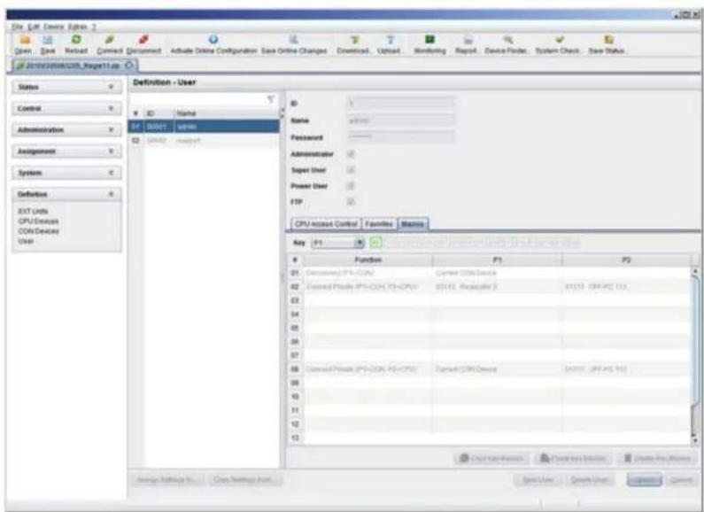
text_image
File Edit Device Options 1 Open - Save - Reload - Command - Discontinued - Admable Online Configuration - Save Online Changes - Download - Upload - Monitoring - Report - Device Finder - System Check - Save Status 201032010320103201032010320103201032010320103201032010320103201032010320103201032010320103201032010320104 Status Control Administration Assignment System Definition EXIT Units CPU/Device COM/Device User Definition - User ID Name ID Address admin WINAD support Name Address Passwd Administrator Super User Power User FTP CPU access Control Favorites Statistics Key F1 Function F1 F2 21 Discontinued: IPI+COSI Current OSOS Device 22 Discontinued: Phase IPI+COSI PS+CPU 8311E, Requestor 3 8311E (SW-PC 156) 23 24 25 26 27 28 Discontinued: Phase IPI+COSI PS+CPU 8311E, Requestor 3 8311E (SW-PC 156) 29 30 31 32 33 Start operations Function Service Create Key Window Save User Create User CancelFIGURE 4-28. DEFINITION-USER
To create a macro for the selected user, proceed as follows:
- Select in the Key field the function key (F1-F16) for which a macro has to be created.
- Select in the Function column the commands that should be part of the macro. The selection list is opened by a double-click on the empty fields.
- Select in the P1 and P2 columns the respective parameters for the macro functions (e.g. corresponding consoles and CPUs).
- Confirm your selections by pressing the Apply button.
For an efficient macro configuration, the following context functions are available:
- Via right-click on the Macros tab, macros can be assigned to other users by using the Assign Macros to ... function and can be copied from other users by using the Copy Macros from ... function.
- Via right-click on the macro list, macros of the selected key can be copied into the cache by using the Copy Key Macros function. You can paste the macros from the cache into a key by using the Paste Key Macros function and you can reset all macros of the selected key by using the Reset Key Macros function.
CHAPTER 4: CONFIGURATION
NEED HELP?
LE AVE THE TECH TO US
LIVE 24/7
TECHNICAL
SUPPORT
1.8 7 7.8 77.2 26 9
4.6 EXTENDER SETTINGS
All extender units are managed in this menu. This includes the creation of new extender units and the deletion of existing extender units.
The extender unit describes the connection of an physical extender to the matrix. Every extender board with a direct cable connection to the matrix is recognized as an extender unit. Dual-Head KVM extenders will be recognized as two independent extender units.
NOTE: KVM Extenders automatically create extender units inside the matrix.
You have the following options to access the menu.


You can select the following settings.
TABLE 4-28. EXTENDER SETTINGS
| FIELD SELECTION DESCRIPTION | ||
| ID Text | Numerical value of the extender ID (KVM extenders: ID is provided by extender unit [Serial No.] and cannot be changed) | |
| Name Text Name of the extender unit | ||
| Fixed | activated Create an extender unit with a fixed port assignment (default) | |
| deactivated Function not active. | ||
| Port 1-288 (depending on the matrix) Port number of the extender unit | ||
CHAPTER 4: CONFIGURATION
NEED HELP?
LE AVE THE TECH TO US
LIVE 24/7
TECHNICAL
SUPPORT
1.8 7 7.87 7.2269
OSD
- Select Configuration > EXT Units in the main menu.
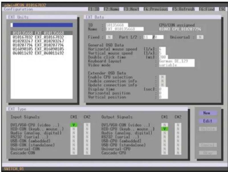
text_image
admin:RCON 010167832 Configuration F1: ID F2: Name F3: Next F4: Previous F5: Refresh F6: Find ESC EXT Units ID : 10135668 CPU/CON assigned Name : EXI_010135668 01003 CPU_010207794 Fixed : N Port 1/2 : 11 20 Universal : N General OSD Data Horizontal mouse speed [1/x]: 4 Vertical mouse speed [1/x]: 5 Double click time [ms]: 200 Keyboard layout : German DE.129 Video mode : variable Extender OSD Data Enable CPU selection : N Enable connection info : N Update connection info : N Display time [sec]: 0 Horizontal position : 0 Vertical position : 0 EXT Type Input Signals CN1 CN2 Output Signals CN1 CN2 DV1/VGA-CPU (video ..) V H DVI/VGA-CON (video ..) N H HID-CON (keyb..mouse.) N H HID-CPU (keyb..mouse.) V H Audio (analog,digital) N H Audio (analog,digital) N H RS232 (serial ..) N H RS232 (serial ..) N H USB-CON (embedded) N H USB-CPU (embedded) N H USB-CON (standalone) N H USB-CPU (standalone) N H Universal-CON N H Universal-CPU N H Cascade-CON N H Cascade-CPU N H New Edit Switch 01FIGURE 4-29. CONFIGURATION—EXT UNITS
You can select the following buttons.
TABLE 4-29. BUTTONS
| BUTTON FUNCTION |
| New Create a new extender unit |
| Edit Edit an existing extender unit |
| Delete Delete an existing extender unit |
| Cancel Reject changes |
| Save Save changes |
The settings fo the OSD Data are described in Section 4.11.2.
CHAPTER 4: CONFIGURATION
NEED HELP? LE AVE THE TECH TO US
LIVE 24/7 TECHNICAL SUPPORT
1.8 7 7.87 7.226 9
JAVA TOOL
- Select Definition >EXT Units in the task area.

text_image
File Edit Device Options 1 Open Save Renew Connect Disconnect Active Online Configuration Save Online Changes Download Uploaded Monitoring Report Device Finder System Check Save Status 20100000000_ReportTitle Status Control Administration Assignment System Definition EXT Units CPU Devices CDH Devices User Definition - EXT Units ID Name Port Type ST I50229682 RL-89111.2011 1 CPU ST I50229683 RL-89211.2011 2 CPU ST I50229670 RL-89211.2011 3 CPU ST I50229684 RL-89311.2012 4 CPU ST I50229689 RL-89311.2012 5 CPU ST I50229671 RL-89311.2012 7 CPU ST I50229673 RL-89311.2012 8 CPU ST I50229674 RL-89311.2012 9 CPU ST I50229675 RL-89311.2012 10 CPU ST I50229676 RL-89311.2012 11 CPU ST I50229677 RL-89311.2012 12 CPU ST I50229678 RL-89311.2012 13 CPU ST I50229679 RL-89311.2012 14 CPU ST I50229680 RL-89311.2012 15 CPU ST I50229681 RL-89311.2012 16 CPU ST I50229682 RL-89311.2012 17 CPU ST I50229683 RL-89311.2012 18 CPU ST I50229684 RL-89311.2012 19 CPU ST I50229685 RL-89311.2012 20 CPU ST I50229686 RL-89311.2012 21 CPU ST I50229687 RL-89311.2012 22 CPU ST I50229688 RL-89311.2012 23 CPU ST I50229689 RL-89311.2012 24 CPU ST I50229690 RL-89311.2012 25 CPU ST I50229691 RL-89311.2012 26 CPU ST I50229692 RL-89311.2012 27 CPU ST I50229693 RL-89311.2012 28 CPU ST I50229694 RL-89311.2012 29 CPU ST I50229695 RL-89311.2012 30 CPU ST I50229696 RL-89311.2012 31 CPU ST I50229697 RL-89311.2012 32 CPU ST I50229698 RL-89311.2012 33 CPU ST I50229699 RL-89311.2012 34 CPU Estimate Type Hardware Version Type CPU Standard here Expert View Name Basic Mod A Mod B Current Digital Audio: HD (system) Camera: Nesting Audio: Digital Audio: USB (CPU subnetwork) USB (CPU subnetwork) Unrealized CPU: Calculator CPU: Design Tools In Data Settings Areas Save and Cancel User Window CancelFIGURE 4-30. DEFINITION—EXT UNITS
You can select the following buttons.
TABLE 4-30. BUTTONS
| BUTTON FUNCTION |
| New Create a new extender unit |
| Delete Delete an existing extender unit |
| Apply Confirm changes of an extender unit |
| Cancel Reject changes |
FLEXIBLE PORT EXTENDER UNITS
Extenders with auto-ID functionality are automatically recognized and cannot be created manually. This is the Flex Port function of the matrix.
CAUTION: The connection of a fixed port extender unit (e.g., USB 2.0) to a Flex-Port can cause unintended results.
CHAPTER 4: CONFIGURATION
4.7 USB 2.0 EXTENDER
This section helps you to configure and use your USB 2.0 extenders. These extenders will have to be connected to standard I/O boards in this case. USB 2.0 extenders can be configured for independent switching or can be assigned to already existing KVM extenders.
You have the following options to access the menu.


OSD
- Select Configuration >EXT Units in the main menu.
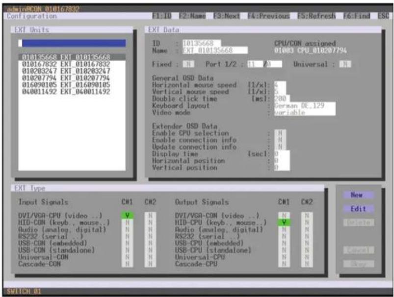
text_image
admiRCON 010167832 Configuration F1:10 F2:Name F3:Next F4:Previous F5:Refresh F6:Find ESC EXT Units 010165658 EXT_010165658 010167832 EXT_010167832 010203247 EXT_010203247 010207794 EXT_010207794 016090105 EXT_016090105 040011492 EXT_040011492 EXT Data ID : 10135668 CPU/CON assigned Name : EXT_010135668 01083 CPU_010207794 Fixed : N Port 1/2 : 11 A Universal : N General OSD Data Horizontal mouse speed [1/x]: 4 Vertical mouse speed [1/x]: 5 Double click time [ms]: 200 Keyboard layout : German OE.129 Video mode : variable Extender OSD Data Enable CPU selection : N Enable connection info : N Update connection info : N Display time [sec]: 0 Horizontal position : 0 Vertical position : 0 EXT Type Input Signals CW1 CW2 Output Signals CW1 CW2 DVI/VGA-CPU [video ..] V N DVI/VGA-CON [video ..] N N HIO-CON [keyb., mouse..] N N HID-CPU [keyb., mouse..] V N Audio (analog, digital) N N Audio (analog, digital) N N RS232 (serial .) N N RS232 (serial .) N N USB-CON (embedded) N N USB-CPU (embedded) N N USB-CON (standalone) N N USB-CPU (standalone) N N Universal-CON N N Universal-CPU N N Cascade-CON N N Cascade-CPU N N New Edit Switch 01FIGURE 4-31. CONFIGURATION—EXT UNITS
- To configure a USB 2.0 extender unit, press the New button. An extender with an eight-digit ID will be created, starting with digit 9.
- Assign an appropriate name to the extender in the Name field.
- Enter the port number of the matrix physically connected to the USB 2.0 extender unit into the Port field.
- To configure the created extender as a CON Unit, set the USB-CON (standalone) option to Y (C#1 in the Input Signals column) and confirm by pressing the Okay button.
- To configure the created extender as a CON Unit, set the USB-CPU (standalone) option to Y (C#1 in the Output Signals column) and confirm by pressing the Okay button.
CHAPTER 4: CONFIGURATION
- To create an individually switchable Device for the USB 2.0 CON extender, select Configuration > CON Devices and press the New R button. Alternatively, you can assign the USB 2.0 CON extender to an already existing CON Device. For this purpose, select the Device and move the USB 2.0 CON extender from the EXT available field into the EXT assigned field.
- Give an appropriate name to the new Device in the Name field.
- Repeat steps 6 and 7 for all USB 2.0 CPU extenders in the Configuration > CPU Devices menu.
- If you use parallel operation within the matrix, set the Release Time in the Configuration > Switch menu to 10 seconds or more (see Section 4.11.6).
- Restart all I/O boards on which USB 2.0 extenders have been configured or alternatively restart the matrix.
The USB 2.0 extenders are now configured and can be used.
JAVA TOOL
- Select Definition > EXT Units in the task area.

text_image
File Edit Device Options Green Save Reset Connect Document Activate Online Configuration Save Online Changes Download Upload Monitoring Report Device Finder System Check Save Status 201800000000_Report13a Status Control Administration Assignment System Definition EXT Units CPU/Devices CON/Devices User Definition - EXT Units ID Name CPU Assigned CPU 1.00 (1.00) Port Fixed Ext Unit CPU Devices CON Devices User 01:05224962 75-101 (1-201) 1 CPU 02:05224963 75-102 (1-201) 2 CPU 03:05224964 75-103 (1-201) 3 CPU 04:05224965 75-104 (1-201) 4 CPU 05:05224966 75-105 (1-201) 5 CPU 06:05224971 75-107 (1-201) 6 CPU 07:05224973 75-108 (1-201) 7 CPU 08:05224974 75-109 (1-201) 8 CPU 09:05224975 75-110 (1-201) 9 CPU 10:05224976 75-111 (1-201) 10 CPU 11:05224977 75-112 (1-201) 11 CPU 12:05224978 75-113 (1-201) 12 CPU 13:05224979 75-114 (1-201) 13 CPU 14:05224980 75-115 (1-201) 14 CPU 15:05224981 75-116 (1-201) 15 CPU 16:05224982 75-117 (1-201) 16 CPU 17:05224983 75-118 (1-201) 17 CPU 18:05224984 75-119 (1-201) 18 CPU 19:05224985 75-120 (1-201) 19 CPU 20:05224986 75-121 (1-201) 20 CPU 21:05224987 75-122 (1-201) 21 CPU 22:05224988 75-123 (1-201) 22 CPU 23:05224989 75-124 (1-201) 23 CPU 24:05224990 75-125 (1-201) 24 CPU 25:05224991 75-126 (1-201) 25 CPU Encoder Settings: Close Settings Form: Name Basic Mod A Mid B USB drive unit : USB drive unit : Digital mode : USB CPU command : USB CPU command : Used in CPUs : Cascade CPUs : Standard View Export View Basic Mod A Mid B OK OK OK ADD / download / mouse : Add mode : Add mode : Add mode : Add mode : Add mode : Add mode : Add mode : Add mode : Add mode : Add mode : Add mode : Add mode : Add mode : Add mode : Add mode : Add mode : Add mode : Add mode : Add mode : Add mode : Add mode : Add mode : Add mode : Add mode : Add mode : Add modes : Add modes : Add modes : Add modes : Add modes : Add modes : Add modes : Add modes : Add modes : Add modes : Add modes : Add modes : Add modes : Add modes : Add modes : Add modes : Add modes : Add modes : Add modes : Add modes : Add modes : Add modes : Add modes : Add modes : Add modes : Add mode : Add mode : Add mode : Add mode : Add mode : Add mode : Add mode : Add mode : Add mode : Add mode : Add mode : Add mode : Add mode : Add mode : Add mode : Add mode : Add mode : Add mode : Add mode : Add mode : Add mode : Add mode : Add mode : Add mode : Add Mode : Add Mode : Add Mode : Add Mode : Add Mode : Add Mode : Add Mode : Add Mode : Add Mode : Add Mode : Add Mode : Add Mode : Add Mode : Add Mode : Add Mode : Add Mode : Add Mode : Add Mode : Add Mode : Add Mode : Add Mode : Add Mode : Add Mode : Add Mode : Add Mode : Add mode : Add mode : Add mode : Add mode : Add mode : Add mode : Add mode : Add mode : Add mode : Add mode : Add mode : Add mode : Add mode : Add mode : Add mode : Add mode : Add mode : Add mode : Add mode : Add mode : Add mode : Add mode : Add mode : Add mode : Add-mode : Show unit: Show Units Cancel: CancelFIGURE 4-32. DEFINITION—EXT UNITS
- Press the New button. A popup window opens.
- Select (Templates) in the selection box, if you want to use a template for a USB 2.0 CON Unit (USB CON Unit) or a USB 2.0 CPU Unit (USB CPU Unit). An extender with an eight-digit ID will be created, starting with digit 9.
- Give an appropriate name to the extender in the Name field.
- Enter the port number of the matrix physically connected to the USB 2.0 extender unit into the Port field.
- Confirm your settings by pressing the Apply button.
- The USB 2.0 CON extender now has to be either assigned to an existing CON Device in the menu Definition > CON Devices or a new CON Device has to be created for the assignment by pressing the New button.
CHAPTER 4: CONFIGURATION
- The USB 2.0 CPU extender now has to be either assigned to an existing CON Device in the Definition > CPU Devices menu or a new CON Device has to be created for the assignment by pressing the New button.
- If you use parallel operation within the matrix, set the Release Time in the Configuration > Switch menu to 10 seconds or more (see Section 4.11.6).
- Restart all I/O boards on which USB 2.0 extenders have been configured or alternatively restart the matrix.
The USB 2.0 extenders are now configured and can be used.
NOTE: Created extender units are always set as fixed-port extenders. This configuration is necessary if you want to switch, e.g. USB 2.0 connections via the matrix.
NOTE: To make a fixed port available again for Flex-Port extender units after deleting a fixed-port extender unit, you must restart the I/O board.
4.8 EXTENDERS FOR UNI I/O BOARDS (USB 2.0/USB 3.0)
This section will help you to configure and use your USB 2.0/3.0 extenders. To use USB 3.0 extenders, you need at least one UNI I/O board and SFP modules based on 6.25 Gbit/s for the matrix.
You have the following options to configure the system:


CHAPTER 4: CONFIGURATION
OSD
- Select Configuration > EXT Units in the main menu.

text_image
SIDIOMCON 010167832 Configuration F1:ID F2:Name F3:Next F4:Previous F5:Refresh F6:Find ESC EXT Units 010135668 EXT 010155668 010167832 EXT 010167832 010203247 EXT 010203247 010207794 EXT 010207794 016890105 EXT 016090105 040011492 EXT_040011492 EXT Data ID : 10135668 CPU/CON assigned Name : IXI 010135668 01008 CPU 010207794 Fixed : N Port 1/2 : 11 A Universal : N General OSD Data Horizontal mouse speed [1/xl] : 4 Vertical mouse speed [1/xl] : 5 Double click time [ms] : 200 Keyboard layout German DE_129 Video mode variable Extender OSD Data Enable CPU selection : N Enable connection info : N Update connection info : N Display time [sec] : 0 Horizontal position : 0 Vertical position : 0 EXT Type Input Signals CM1 CM2 Output Signals CM1 CM2 DVI/VGA-CPU [video ..] V H DVI/VGA-CON [video ..] H N HID-CON [kevb..mouse..] H HID-CPU [kevb..mouse..] V N Audio (analog, digital) H H IIO (analog, digital) H N RS232 (serial ..) H RS232 (serial ..) H N USB-CON (embedded) H USB-CPU (embedded) H N USB-CON (standalone) H USB-CPU (standalone) H N Universal-CON H Universal-CPU H N Cascade-CON H Cascade-CPU H N New Edit SWITCH 01FIGURE 4-33. CONFIGURATION—EXT UNITS
- Insert the SFP modules into the matrix and connect the extenders according to the required application.
One extender will be created for each SFP module in the EXT Units list. The appropriate names always start with "UNI." - To configure a CON Unit, select one of the extenders in the EXT Units list that are physically connected to a USB CON Unit.
- Edit the extender by setting the USB-CON (standalone) option in the Input Signals field to Y for C#1. Set also the Universal-CPU option in the Output Signals field to N for C#1.
- To configure a CPU Unit, select one of the extenders in the Ext Units list that are physically connected to a USB CPU Unit.
- Edit the extender by setting the USB-CPU (standalone) option in the Output Signals field to Y for C#1. Set also the Universal-CPU option in the Input Signals field to N for C#1.
- The edited EXT Units for the respective USB CON Units now have to be either assigned to an existing CON Device or you have to create a new CON Device by using the New R. button for an assignment in the Configuration > CON Devices menu
- The edited EXT Units for the respective USB CPU Units now have to be either assigned to an existing CPU Device or you have to create a new CPU Device by using the New R. button for an assignment in the Configuration > CPU Devices menu.
- If you use parallel operation within the matrix, set the Release Time in the Configuration > Switch menu to 10 seconds or more.
- Restart the matrix.
The USB extenders are completely configured now and can be used.
CHAPTER 4: CONFIGURATION
JAVA TOOL
- Select Definition >EXT Units in the task area.

text_image
File Edit Device Options Gmail - Save Refresh Comment Adjust Active Online Configuration Save Online Changes Download Update Monitoring Report Device Finder System Check Save Status 2019/03/06/2019_Ragv11篇 - 01 Status Control Administration Assignment System Definition EXT Units CPU Devices CON Devices User Definition - EXT UnitsID
Name Port Type ID HKEYNOTE CPU Assigned 2019.03.06/2019.03.07 Name Port: Fixed Encoder Type Hardware Version Type CPU Standard View Export View Name Basic Mod A Mod B COMEXOMICA version 1 COMEXOMICA version 2 AMD Interface Version 1 Analog Inbit 1 Digital Audio 1 WSDI/PADJ Service 1 COM CPU Services 1 USB CPU Services 1 Universe CPU 1 Cascade CPU 1 Import Settings 5 Copy Settings 50000000000000000000000000000000000000000000000000000000000000000000000000000000000000000000000000000FIGURE 4-34. DEFINITION—EXT UNITS
- Insert the SFP modules into the matrix and connect the extender according to the required application.
One extender will be created for each SFP module in the Ext Units list. The appropriate names always start with "UNI." - To configure a CON Unit, select one of the extenders in the Ext Units list that are physically connected to a USB CON Unit.
- Select the item UNI CON USB in the Type selection box of the Extender Type tab and confirm your settings by pressing the Apply button.
- Restart the I/O board upon request in the popup window by pressing the Yes button.
- To configure a CPU Unit, select one of the extenders in the Ext Units list that are physically connected to a USB CPU Unit.
- Select the item UNI CPU USB in the Type selection box of the Extender Type tab and confirm your settings by pressing the Apply button.
- Restart the I/O board upon request in the popup window by pressing the Yes button.
- The edited EXT Units for the respecting USB CON Units now have to be either assigned to an existing CON Device or you have to create a new CON Device by using the New button for an assignment in the Definition >CON Devices menu.
- The edited EXT Units for the respecting USB CPU Units now have to be either assigned to an existing CPU Device or you have to create a new CPU Device by using the New button for an assignment in the Definition >CPU Devices menu.
- If you use parallel operation within the matrix, set the Release Time in the System > Switch menu to 10 s or more (). The USB extenders are completely configured now and can be used.
CHAPTER 4: CONFIGURATION
4.9 CONFIGURATION OF SDI
This section will help you to configure the matrix for the use of SDI. Using SDI requires at least one I/O board and appropriate SFP modules according to the SDI video signal to be used.


OSD
- Select Configuration >EXT Units in the main menu.
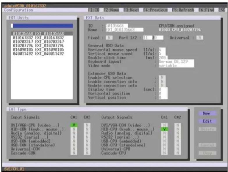
text_image
admin:PCON 010167832 Configuration F1:10 F2:Name E3:Next F4:Previous FS:Refresh F5:Find ESG EXT Units ID : 10135668 CPU/CON assigned Name : EXT_010135668 01003 CPU_01020794 Fixed : N Port 1/2 : (1 A) Universal : N General OSD Data Horizontal mouse speed [1/x]: 4 Vertical mouse speed [1/x]: 5 Double click time [ms]: 200 Keyboard layout German DE_129 Video mode variable Extender OSD Data Enable CPU selection : N Enable connection info : N Update connection info : N Display time [sec]: 0 Horizontal position : 0 Vertical position : 0 EXT Type Input Signals CW1 CW2 Output Signals CW1 CW2 DVI/VGA-CPU [video ..] V N DVI/VGA-CON [video ..] N N HID-CON [keyb.. mouse..] N HID-CPU [keyb.. mouse..] V N Audio [analog. digital] N HAudio [analog. digital] N N RS232 (serial ..) N HRS232 (serial ..) N N USB-CON (embedded) N HUSB-CPU (embedded) N N USB-CON (standalone) N HUSB-CPU (standalone) N N Universal-CON N HUniversal-CPU N N Cascade-CON N H Cascade-CPU N N New Edit Switch_01FIGURE 4-35. CONFIGURATION—EXT UNITS
- Insert the SFP modules into the matrix. One extender will be created for each SFP module in the EXT Units list. The appropriate names always start with "UNI."
- To configure an SDI input, select one of the extenders in the EXT Units list that corresponds to the respective SFP and is intended to be used as input.
- Edit the extender by setting the Universal-CPU option in the Output Signals field to Y for C#1. Set also the Universal-CON option in the Input Signals field to N for C#1.
- To configure an SDI output, select one of the extenders in the EXT Units list that corresponds to the respective SFP and is intended to be used as output.
- Edit the extender by setting the Universal-CON option in the Input Signals field to Y for C#1. Set also the Universal-CPU option in the Output Signals field to N for C#1.
CHAPTER 4: CONFIGURATION
-
The edited EXT Units for the SDI inputs now have to be either assigned to an existing CPU Device or you have to create a new CPU Device by using the New R. button for an assignment in the Configuration > CPU Devices menu.
-
The edited EXT Units for the SDI outputs now have to be either assigned to an existing CON Device or you have to create a new CON Device by using the New R. button for an assignment in the Configuration > CON Devices menu.
-
Restart the Matrix.
The SDI inputs and outputs are completely configured now and can be used.
JAVA TOOL
- Select Definition > EXT Units in the task area.

text_image
File Edit Device Euts Open Save Relaid Connect Disconnect Activate Online Configuration Save Online Changes Download Upload Working Report Device Finder System Check Save Status 2019/03/08/16:05, Report 11.14 - 0 Status Control Administration Assignment System Definition EXT Unit CPU Device COR Devices User Definition - EXT Units ID Name Port Type 01 010220002 75-551+/-250 1 CPU 02 010220003 75-552+/-250 2 CPU 03 010220003 75-553+/-250 3 CPU 04 010220003 75-554+/-250 4 CPU 05 010220003 75-555+/-250 5 CPU 06 010220003 75-556+/-250 6 CPU 07 010220003 75-557+/-250 7 CPU 08 010220003 75-558+/-250 8 CPU 09 010220003 75-559+/-250 9 CPU 10 010220003 75-560+/-250 10 CPU 11 010220003 75-561+/-250 11 CPU 12 010220003 75-562+/-250 12 CPU 13 010220003 75-563+/-250 13 CPU 14 010220003 75-564+/-250 14 CPU 15 010220003 75-565+/-250 15 CPU 16 010220003 75-566+/-250 16 CPU 17 010220003 75-567+/-250 17 CPU 18 010220003 75-568+/-250 18 CPU 19 010220003 75-569+/-250 19 CPU 20 010220003 75-570+/-250 20 CPU 21 010220003 75-571+/-250 21 CPU 22 010220003 75-572+/-250 22 CPU 23 010220003 75-573+/-250 23 CPU 24 010220003 75-574+/-250 24 CPU 25 010220003 75-575+/-250 25 CPU 26 010220003 75-576+/-250 26 CPU END Subnet Version CPU Assigned SMM A SMM B Name SMM A SMM B Port Fload Editor Type Fromset Version Type Standard View Export View Name Break Mid-A Mid-S Continuous name : C# D# D# NCC (constant name) : C# D# SIP (Auto) : C# Digital Audio : C# RSD (RSD) (current): C# USB-CPU (seconds): C# Universe-CPU : C# Código-CPU : C# Design Link Complete Link ControlFIGURE 4-36. DEFINITION—EXT UNITS
- Insert the SFP modules into the matrix.
One extender will be created for each SFP module in the EXT Units list. The appropriate names always start with "UNI." - To configure an SDI input, select one of the extenders in the EXT Units list that corresponds to the respective SFP and is intended to be used as input.
- Select the item UNI CPU in the Type selection box of the Extender Type tab and confirm your settings by pressing the Apply button.
- Restart the I/O board upon request in the popup window by pressing the Yes button.
- To configure an SDI output, select one of the extenders in the EXT Units list that corresponds to the respective SFP and is intended to be used as output.
- Select the item UNI CON in the Type selection box of the Extender Type tab and confirm your settings by pressing the Apply button.
- Restart the I/O board upon request in the popup window by pressing the Yes button.
- The edited EXT Units for the SDI inputs now have to be either assigned to an existing CPU Device or you have to create a new CPU Device by using the New R. button for an assignment in the Configuration > CPU Devices menu.
- The edited EXT Units for the SDI outputs now have to be either assigned to an existing CON Device or you have to create a new CON Device by using the New R. button for an assignment in the Configuration > CON Devices menu.
CHAPTER 4: CONFIGURATION
The SDI inputs and outputs are completely configured now and can be used.
4.10 CPU SETTINGS
New CPU Devices are configured in this menu including their assignment to extenders.
The assignment helps to describe and switch more complex computer configurations (e.g. Quad-Head with USB 2.0) in the matrix.
You have the following options to access the menu.


You can select the following settings.
TABLE 4-31. CPU SETTINGS
| FIELD SELECTION DESCRIPTION | |
| ID Text ID of the CPU Unit (see Section 4.4.2) | |
| Name Text Name of the CPU Device | |
| Virtual Device | activated Create new CPU Device as a virtual one |
| deactivated Function not active (default) | |
| Allow Private | activated Allow switching to the respective CPU Device in Private Mode |
| deactivated Function not active (default) | |
| Force Private | activated Force switching to the respective CPU only in Private Mode |
| deactivated Function not active (default) | |
| Fix Frame | activated Force showing a red frame when switching to the respective CPU |
| deactivated Function not active (default) | |
CHAPTER 4: CONFIGURATION
NEED HELP?
LE AVE THE TECH TO US
LIVE 24/7
TECHNICAL
SUPPORT
1.8 7 7.87 7.2269
OSD
- Select Configuration > CPU Units in the main menu.

text_image
01000 @ 03000 CON 010125369 - admin Configuration F1:ID F2:Name F3:Next F4:Previous F5:Refresh F6:Find ESC CPU Devices 01000 CPU 010124911 01001 CPU_010129232 01002 CPU_010129250 01003 CPU_010144317 02000 VCPU_02000 CPU Data ID : 1000 CPU assigned Name : CPU_010124911 Virtual Device : N CON connected Allow Private : N Force Private : N FIX Frame : N EXT available EXT assigned 010124911 044 EXT_10124911 New R. New V. Edit Delete Forward Copy Enter a name to find an item SUPPORTFIGURE 4-37. CONFIGURATION—CPU DEVICES
You can select the following buttons.
TABLE 4-32. BUTTONS
| BUTTON FUNCTION | |
| New R. Create a new real CPU device | |
| New V. Create a new virtual CPU device | |
| Edit Edit an existing CPU device | |
| Delete Delete an existing CPU device | |
| Cancel Reject changes | |
| Save | Save changes |
CHAPTER 4: CONFIGURATION
NEED HELP? LE AVE THE TECH TO US
LIVE 24/7 TECHNICAL SUPPORT
1.8 7 7.87 7.2269
JAVA TOOL
- Select Definition > CPU Devices in the task area.
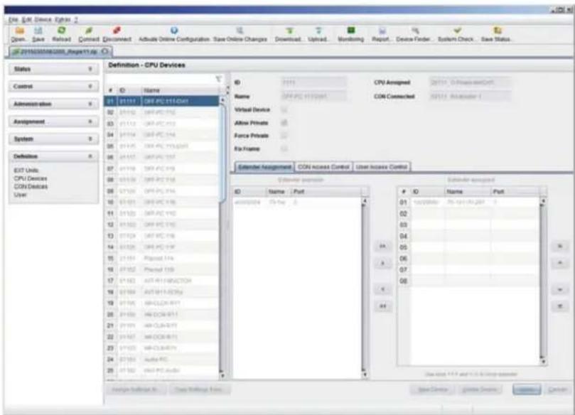
text_image
File Edit Device Options 2 Open Save Reload Connect Discount Active Online Configuration Save Online Changes Download Upload Monitoring Report Device Finder System Check Save Status 2016308888888888888888888888888888888888888888888888888888888888888888888888 Status Control Administration Assignment System Definition EAST Units CPU Devices CON Devices User Definition - CPU Devices ID Name 01 P1111 OR PC 911-Def 02 P1112 OR PC 912 03 P1113 OR PC 913 04 P1114 OR PC 914 05 P1115 OR PC 915-0205 06 P1117 OR PC 916 07 P1119 OR PC 919 08 P1120 OR PC 916 09 P1123 OR PC 916 10 P1125 OR PC 916 11 P1127 OR PC 916 12 P1129 OR PC 916 13 P1130 OR PC 916 14 P1132 OR PC 916 15 P1134 PIased 916 16 P1136 PIased 916 17 P1139 ATR RCL#N/CCT04 18 P1140 ATR RCL#N/C76a 19 P1145 ATR CCL#N/RIT 20 P1146 ATR CCL#N/RIT 21 P1147 ATR CCL#N/RIT 22 P1149 ATR CCL#N/RIT 23 P1150 ATR CCL#N/RIT 24 P1152 Audio PC 25 P1153 Audio PC Audio ID Name / Port Name / Port Virtual Device Allow Private Force Private Ris Frame Calendar Assignment CON Access Control User Interface Control Operator: http://www.elsevier.com/ Calendar assignment ID Name / Port 01 T5-mp 3 02 03 04 05 06 07 08 09 Sub-List: 1/3 and 2/3 in the operatorFIGURE 4-38. DEFINITION—CPU DEVICES
You can select the following buttons.
TABLE 4-33. BUTTONS
| BUTTON FUNCTION | |
| New Open a new CPU device | |
| Delete Delete a new CPU device | |
| Apply Confirm a created CPU device | |
| Cancel Reject changes | |
| > Assign selected extender units | |
| >> | Assign all available extender units |
| < Remove selected extender units | |
| << | Remove all extender units |
You can select the following keyboard commands.
TABLE 4-34. KEYBOARD COMMANDS
| FUNCTION | KEYBOARD COMMAND |
| Change assignment number of EXT unit upwards | <++> |
| Change assignment number of EXT unit downwards | <--> |
CHAPTER 4: CONFIGURATION
NEED HELP?
LE AVE THE TECH TO US
LIVE 24/7
TECHNICAL
SUPPORT
1.87 7.87 7.2 269
To create a new CPU Device, proceed as follows:
- Press the New button.
- Select a real CPU (Create a real CPU) or a virtual CPU (Create a virtual CPU) or a template of an existing CPU (Choose template). NOTE: A template can only be used if there is at least one existing CPU Device.
- Press the OK button.
- Determine all parameters that are relevant for the CPU.
- To confirm the new CPU, press the Apply button.
To access a new CPU via matrix, an assignment of one or more CPU type extender units is required. Proceed as follows:
- Select the new CPU in the CPU Devices list.
- Select one or more extenders in the Extender available list.
- Perform the assignment by pressing the > button. To assign all available extenders to the CPU, press the >> button.
The assignments are displayed in the Extender assigned list. - Confirm the assignment by pressing the Apply button.
To remove an extender assignment, proceed as follows:
- Select a CPU in the CPU Devices list.
- Select one or more extenders in the Extender assigned list.
- Remove the assignment with the < button. To remove all existing assignments, press the << button.
- Confirm the removal with the Apply button.
4.11 CONSOLE SETTINGS
You have the option to perform the following console settings.
4.11.1 CON DEVICES
New CON Devices are created in this menu including access rights and assignment to extenders.
You have the following options to access the menu.


CHAPTER 4: CONFIGURATION
You can select the following settings.
TABLE 4-35. CON DEVICES SETTINGS
| FIELD SELECTION DESCRIPTION | ||
| ID Text ID of the CON Unit (see Section 4.4.2) | ||
| Name Text Name of the CON Device | ||
| Virtual Device | activated Create new CON Device as a virtual one | |
| deactivated Function not active (default) | ||
| Allow User ACL | activated Allow activation of the User ACL at the local console | |
| deactivated Function not active (default) | ||
| Force Login | activated Force user login at this CON Device | |
| deactivated Function not active (default) | ||
| LOS Frame | activated | When the video signal between source (computer, CPU) and the CPU Unit or the connection between matrix and the CON Unit is lost, an orange frame will be displayed.When switching to a CPU without video signal, a blank screen will appear surrounded by an orange frame. |
| deactivated Function not active (default) | ||
| Allow CPU Scan | activated | Allow a scan mode with an automatic change of the video signal for the favorite list (CPU Devices) of the respective console or a logged in user |
| deactivated Function not active (default) | ||
| Force CPU scan | activated | Force a scan mode with an automatic change of the video signal for the favorite list (CPU Devices) of the respective console or a logged in user |
| deactivated Function not active (default) | ||
| Scan Time | 0-99 seconds | Retention period until switching to the next CPU Device |
| Port Mode | activated | The favorite list will be replaced by a port list where the ports from 1-99 can be directly selected at each matrix.NOTE: The selection only works for CPU Devices and has to be made according to the switching of favorites.When using the Port Mode, CON and User favorites will be deactivated |
| deactivated Function not active (default) | ||
| Redundancy OFF | activated Function not active | |
| deactivated | Automatically switch to the second link of a connected redundant CON Unit when losing the primary link of a CPU Unit (default) | |
CHAPTER 4: CONFIGURATION
NEED HELP?
LE AVE THE TECH TO US
LIVE 24/7
TECHNICAL
SUPPORT
1.8 7 7.87 7.2269
OSD
- Select Configuration > CON Devices in the main menu.

text_image
adiraACON 010167832 Configuration F1: ID F2: Name F3: Next F4: Previous F5: Refresh F6: Find ESC CON Devices 03002 CON 010167832 03001 CON_010203247 CON Data ID : 0002 Name : CON 010167832 Virtual Device : N Allow User RCL : N Force Login : N LOS Frame : N EXT available CON assigned Allow CPU Scan : N Force CPU Scan : N Scan Time Isec1: 0 Port Mode : N Redundancy Off : N EXT assigned 010167832 033 EXT_010167832 010203247 034 EXT_010203247 CPU Access Control List Full access Video access No access 01002 CPU_010135668 01003 CPU_010207794 01001 CPU_016898105 01004 CPU_040011492 New R. New V. Edit Delete Switch 01FIGURE 4-39. CONFIGURATION—CON DEVICES
You can select the following buttons.
TABLE 4-36. BUTTONS
| BUTTON FUNCTION | |
| New R. Create a real console | |
| New V. Create a virtual console | |
| Edit Edit an existing console | |
| Delete Delete an existing console | |
| Cancel Reject changes | |
| Save | Save changes |
CHAPTER 4: CONFIGURATION
NEED HELP? LE AVE THE TECH TO US
LIVE 24/7 TECHNICAL SUPPORT
1.8 7 7.87 7.2269
JAVA TOOL
- Select Definition > CON Devices in the task area.
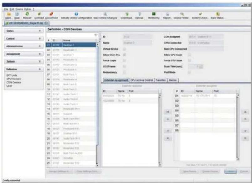
text_image
File Edit Device Options 1 Open Save Reset Command Discontinued Activate Online Configuration Save Online Changes Download Upload Monitoring Report. Device Finder System Check... Save Status 201530584201_Reporting Status Control Administration Assignment Systems Definition EVI Units CPU Devices ODN Devices User Definition - OON Devices ID Name 01 01/12 Grafer 2 02 01/14 Realizer 1 03 01/21 Grafer 1 04 01/13 Realizer 3 05 01/12 Analog 2 06 01/21 Prolactor 1 07 01/14 Multi Tech 1 08 01/14 Realizer 4 09 01/42 Multi Tech 2 10 01/43 Multi Tech 3 11 01/47 Audio Tech 1 12 01/42 Audio Tech 2 13 01/43 Audio Tech 3 14 01/11 Realizer 9/11 15 04/15 Supplint 16 01/34 Multi Tech 9/31 17 04/30 Multi Tech 9/11 18 04/25 Prolactor 9/11 19 04/37 Grafer 9/11 20 04/43 Audio Tech 9/11 21 04/34 Monotonic 9/37 22 04/43 Monotonic 9/37 23 04/38 Multi Tech 4x2(4) 24 03/43 Extricate 25 03/43 Monotonic 9/37 CON Assigned 01:57, Status: 8.5.1 CPU Connected: 01:58, Connection: Red. CPU Connected: Allow User ACL Allow CPU Scan: Force Logic: Force CPU Scan: LED Frame: Scas New [sec] Redundancy: Port Mode: Extension Assignment: CPU Access Control: Favorites: Statistics Extension assessor: ID Name Post ID Name Post ID Name Post ID Name Post ID Name Post ID Name Post ID Name Post ID Name Post ID Name Post ID Name Post ID Name Post ID Name Post ID Name Post ID Name Post ID Name Post ID Name Post ID Name Post ID Name Post ID Name Post ID Name Post ID Name Post ID Name Post ID Name Post ID Name Post ID Name Post ID Name Post ID Name Post ID Name Post ID Name Post ID Name Post ID Name Post ID Name Post ID Name Post ID Name Post ID No Config returnedFIGURE 4-40. DEFINITION—CON DEVICES
You can select the following buttons.
TABLE 4-37. BUTTONS
| BUTTON FUNCTION | |
| New Open a new CON device | |
| Delete Delete a new CON device | |
| Apply Confirm a created CON device | |
| Cancel Reject changes | |
| > Assign selected extender units | |
| >> | Assign all available extender units |
| < Remove the selected extender units | |
| << | Remove all extender units |
You can select the following keyboard commands.
TABLE 4-38. KEYBOARD COMMANDS
| FUNCTION | KEYBOARD COMMAND |
| Decrease assignment number of EXT unit | <-> |
| Increase assignment number of EXT unit | <-> |
CHAPTER 4: CONFIGURATION
To create a new console, proceed as follows:
- Press the New button.
- Select a real console (Create a real Console) or a virtual console (Create a virtual Console) or a template of an existing console (Choose template).
NOTE: A template can only be used if there is at least one existing CON Device.
- Press the OK button.
- Determine all parameters that are relevant for the console.
- To confirm a created console, press the Apply button.
To run a CPU via a matrix, one or more CON Units (extender) must be assigned. To place an assignment, proceed as follows:
- Select the console in the CON Devices list that has to be assigned to an extender.
- Select the extender in the Extender available list that should be assigned to the CON.
- Perform the assignment by pressing the > button. To assign all available extenders to the console, press the >> button. The assignments are displayed in the Extender assigned list.
- Confirm the assignment by pressing the Apply button.
To remove an extender assignment, proceed as follows:
- Select the console in the CON Devices list to be modified.
- Select the extender(s) in the Extender assigned list to be removed.
- Remove the assignment with the < button. To remove all existing assignments, press the << button.
- Confirm the changes by pressing the Apply button.
To configure CPU access rights of consoles, proceed as follows:
- Select a console in the CON Devices list.
- Open the CPU Access Control tab.
- Assign new access rights by using the right mouse button or the respective keyboard commands.
- Confirm the configuration by pressing the Apply button.
You can select the following keyboard commands.
TABLE 4-39. KEYBOARD COMMANDS
| FUNCTION KEYBOARD COMMAND |
| Add CPU to Full Access list |
| Add CPU to Video Access list |
| Add CPU to No Access list |
CHAPTER 4: CONFIGURATION
NEED HELP?
LE AVE THE TECH TO US
LIVE 24/7
TECHNICAL
SUPPORT
1.87 7.87 7.2 26 9
4.11.2 MOUSE AND KEYBOARD
The OSD configuration for mouse and keyboard is made in this menu.
You have the following options to access the menu.


You can select the following settings.
TABLE 4-40. MOUSE AND KEYBOARD SETTINGS
| FIELD SELECTION DESCRIPTION | ||
| Hor. Speed 1/x | 1-9 | Adjustment of the horizontal mouse speed, 1 = slow, 9 = fast (default value: 4) |
| Ver. Speed 1/x | 1-9 | Adjustment of the vertical mouse speed, 1 = slow, 9 = fast (default value: 5) |
| Double Click | 100-800 | Adjustment of the time slot for a double click (default value: 200 ms) |
| Keyboard layout | Region | Set the OSD keyboard layout according to the used keyboard (default: German [DE]) |
| Video Mode | Variable or specific resolution | Resolution that is used when opening OSD |
NOTE: The mouse and keyboard settings are console specific and can be set separately for each console.
CHAPTER 4: CONFIGURATION
NEED HELP?
LE AVE THE TECH TO US
LIVE 24/7
TECHNICAL
SUPPORT
1.8 7 7.87 7.2269
OSD
- Select Configuration > EXT Units in the main menu.

text_image
admin#CON_010167832 Configuration F1:ID F2:Name F3:Next F4:Previous ES:Refresh F5:Find ESC EXI Units 010135668 EXT_010135668 010167832 EXT_010167832 010203247 EXT_010203247 010207794 EXT_010207794 016090105 EXT_016090105 040011492 EXT_040011492 EXI Data ID : 10135668 CPU/CON assignments Name : EXT_010135668 01003 CPU_010207794 Fixed : N Port 1/2 : 11 /3 Universal : N General OSD Data Horizontal mouse speed [1/x]: 4 Vertical mouse speed [1/x]: 5 Double click time [sec]: 200 Keyboard layout : German DE.129 Video mode : variable Extender OSD Data Enable CPU selection : N Enable connection info : N Update connection info : N Display time [sec]: 0 Horizontal position : 0 Vertical position : 0 EXI Type Input Signals CM1 CM2 Output Signals CM1 CM2 DVI/VGA-CON (video ..) V N DVI/VGA-CON (video ..) HND-CPU (keyb.. mouse..) V N HID-CON (keyb.. mouse..) N N HID-CON (keyb.. mouse..) RSD-CPU (serial ..) N N RS232 (serial ..) N N Audio (analog, digital) N N Radio (analog, digital) N N RS232 (serial ..) N N RS232 (serial ..) N N USB-CON (embedded) N N USB-CPU (embedded) N N USB-CON (standalone) N N USB-CPU (standalone) N N Universal-CON N N Universal-CPU N N Cascade-CON N N Cascade-CPU N N New Edit Next > Cancel Next SUPPORT ONFIGURE 4-41. DEFINITION—EXT UNITS
You can select the following buttons.
TABLE 4-41. BUTTONS
| BUTTON FUNCTION |
| Cancel Reject changes |
| Save Save changes |
CHAPTER 4: CONFIGURATION
NEED HELP?
LE AVE THE TECH TO US
LIVE 24/7
TECHNICAL
SUPPORT
1.877.877.2269
JAVA TOOL
- Select Configuration > EXT Units in the task area.
NOTE: Mouse and keyboard settings are made in the OSD Data tab.

text_image
COM Engine User GO: 01.01.01.01.01 Open, Save - Reload, Connect, Unconnect - Active Online Configuration Save Online Changes Download, Upload, Monitoring, Report, Device Finder, System Check, Save Status... ServiceCount/Unit_Reported up Status Control Administration Assignment System Definition EXT Units CPU/Device COM/Device User Definition - EXT Units ID Name Port Type 25 25 25 25 25 25 25 25 25 25 25 25 25 25 25 25 25 25 25 25 25 25 25 25 25 25 25 25 25 25 25 25 25 25 ID Name Port Fixed Encoder Type Firmware Version General CMD Data External CMD Data Horizontal Mouse Speed (Hz) Vertical Mouse Speed (Hz) Disable Click Time (ms) Keyboard Layout Video Mode 40 40 40 40 40 40 40 40 40 40 40 40 40 40 40 40 40 40 40 40 40 40 40 40 40 40 40 40 40 40 40 40 40 40 38 COM 16.671.01.01.01.01.01.01.01.01.01.01.01.01.01.01.01.01.01.01.01.01.01.01.01.01.01.01.01.01.01.01.01.01.01.03 COM Assigned COM Assigned Service, Software Tools 2 Horizontal Mouse Speed (Hz) Vertical Mouse Speed (Hz) Disable Click Time (ms) Keyboard Layout: Video Mode COM Assigned Service Unit 3 COM Assigned Service Unit 3 COM Assigned Service Unit 3 COM Assigned Service Unit 3 COM Assigned Service Unit 3 COM Assigned Service Unit 3 COM Assigned Service Unit 3 COM Assigned Service Unit 3 COM Assigned Service Unit 3 COM Assigned Service Unit 3 COM Assigned Service Unit 3 COM Assigned Service Unit 3 COM Assigned Service Unit 3 COM Assigned Service Unit 3 COM Assigned Service Unit 3 COGS Default Rate Crip Default Rate Select CDS: 1.9% CancelFIGURE 4-42. DEFINITION—EXT UNITS
CHAPTER 4: CONFIGURATION
4.11.3 EXTENDER OSD
In this menu, the settings for the Extender OSD can be adjusted. These are local settings that can be made individually for each console.
You can select the following Extender OSD settings.
TABLE 4-42. EXTENDER OSD SETTINGS
| FIELD SELECTION DESCRIPTION | ||
| Enable CPU Selection List | activated | When executing the key sequence for opening the OSD, a selection list for switching CPU Devices will be displayed in the center of the monitor. Pressing thebutton within the selection list opens the standard OSD. |
| deactivated Function not active (default) | ||
| Enable Connection Info | activated Enable Extender OSD (default: YES) | |
| deactivated Function not active | ||
| Update Connection Info | activated Update connection changes during fade-in of Extender OSD (default: YES) | |
| deactivated Function not active | ||
| Display Time | 0–999 seconds | Duration of OSD fade-in (default: 10) |
| Horizontal Position | 10 pixels | Horizontal OSD position (default: -2) |
| Vertical Position | 10 pixels | Vertical OSD position (default: 2) |
NOTE: When setting the horizontal OSD position, a prefixed minus describes the orientation to the right edge of the monitor, e.g. -2 means 2 × 10 = 20 pixels to this edge. When setting a vertical position, a prefixed minus describes the orientation to the bottom edge of the monitor.
If the Update Connections function is deactivated, the Extender OSD only appears when switching via OSD.
You have the following options to access the menu.


CHAPTER 4: CONFIGURATION
NEED HELP? LE AVE THE TECH TO US
LIVE 24/7 TECHNICAL SUPPORT
1.8 7 7.8 77.2 26 9
OSD
- Select Configuration > EXT Units in the main menu.
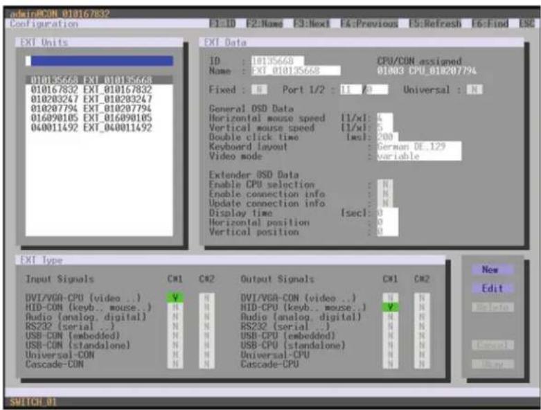
text_image
adminRCON 010167832 Configuration F1: ID F2: Name F3: Next F4: Previous F5: Refresh F6: Find ESC EXI Units ID : 10135668 Name : EXI_010135668 CPU/CON assigned 01003 CPU_010207794 Fixed : N Port 1/2 : 11 A Universal : N General OSD Data Horizontal mouse speed [1/xl] : 4 Vertical mouse speed [1/xl] : 5 Double click time [sec] : 200 Keyboard Layout German OE_129 Video mode variable Extender OSD Data Enable CPU selection : N Enable connection info : N Update connection info : N Display time [sec] : 0 Horizontal position : 0 Vertical position : 0 EXT Type Input Signals CM1 CM2 Output Signals CM1 CM2 DVI/VGA-CPU [video ..] V H DVI/VGA-CON [video ..] N N HID-CON [keyb.. mouse..] H HID-CPU [keyb.. mouse..] V H Audio [analog, digital] N H Audio [analog, digital] N H RS232 (serial ..) N H RS232 (serial ..) N H USB-CON [embedded] N H USB-CPU [embedded] N H USB-CON (standalone) N H USB-CPU (standalone) N H Universal-CON N H Universal-CPU N H Cascade-CON N H Cascade-CPU N H New Edit Edit Date New Switch 01FIGURE 4-43. CONFIGURATION—EXT UNITS
To change the Extender OSD settings, proceed as follows:
- Select the console extender in the EXT Units list whose Extender OSD settings has to be adjusted.
- When confirming the selection by pressing
, the respective console extender will be enabled for editing.
CHAPTER 4: CONFIGURATION
NEED HELP? LE AVE THE TECH TO US
LIVE 24/7 TECHNICAL SUPPORT
1.8 77.8 77.2 26 9
JAVA TOOL
- Select Definition >EXT Units in the task area.
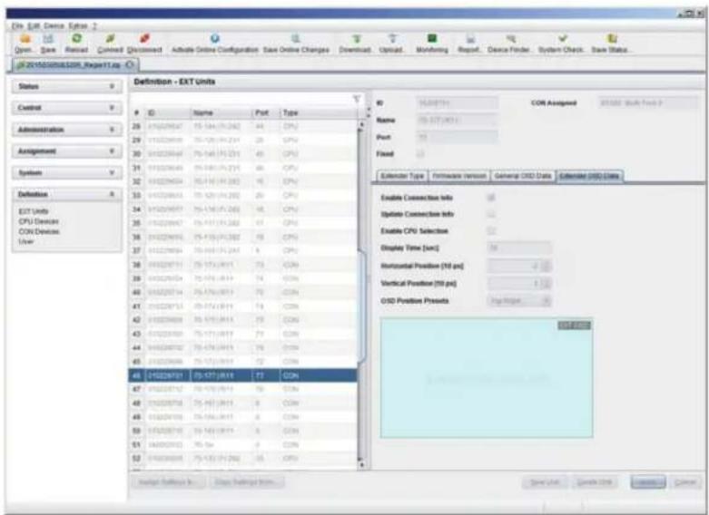
text_image
File Edit Device Options 2 Open... Save Next Reset Cancel Discount Admable Online Configuration Save Online Changes Download. Upload: Monitoring Report Device Finder System Check Save Status... #201503008/03208_Report1.jpg Status Control Administration Assignment System Definition EXT Units CPU Devens CON Devices User ID Name COM Assigned COM Assignment 05.05.07.041 Port: Fixed Exclender Type Firmware Version General OIS Data Extended OIS Data Enable Connection Info Update Connection Info Enable CPU Selection Display Time [arc] Horizontal Position [70 pc] Vertical Position [70 pc] OIS Positive Results OK OK OK OK OK OK OK OK OK OK OK OK OK OK OK OK OK OK OK OK OK OK OK OK OK OK OK OK OK OK OK OK OK OK OK OK OK OK OK OK OK OK OK OK OK OK OK OK OK OK OK OK OK OK OK OK OK OK OK OK OK OK OK OK OK OK OK OK OK OK OK OK OK OK OK OK OK OK Okn OK Okn OK Okn OK Okn OK Okn OK Okn OK Okn OK Okn OK Okn OK Okn OK Okn OK Okn OK Okn OK Okn OK Okn OK Okn OK Okn OK Okn OK Okn OK Okn OK Okn OK Okn OK Okn OK Okn OK Okn OK Okn ON/OIS/OIS/OIS/OIS/OIS/OIS/OIS/OIS/OIS/OIS/OIS/OIS/OIS/OIS/OIS/OIS/OIS/OIS/OIS/OIS/OIS/OIS/OIS/OIS/OIS/OIS/OIS/OIS/OIS/OIS/OIS/OIS/OIS/Ois OK Okn OK Okn OK Okn OK Okn OK Okn OK Okn OK Okn OK Okn OK Okn OK Okn OK Okn OK Okn OK Okn OK Okn OK Okn OK Okn OK Okn OK Okn OK Okn OK Okn OK Okn OK Okn OK Okn OK Okn OK Okn OK Okn OK Okn OK Okn OK Okn OK Okn OK Okn OK Okn OK Okn OK Okn OKFIGURE 4-44. DEFINITION—EXT UNITS
To change the Extender OSD settings, proceed as follows:
- Select the console extender in the EXT Units list for which the Extender OSD settings are to be adjusted.
- Open the Extender OSD Data tab.
- Adjust the desired settings and confirm your changes by pressing the Apply button.
4.11.4 FAVORITE LIST CONSOLES
Individual favorite lists of CPUs to be switched frequently can be created for all consoles in this menu. A favorite list can contain up to 16 different CPUs.
The switching of the favorites is done via hotkey using the keyboard (see Section 5.1.1).
You have the following options to access the menu.


CHAPTER 4: CONFIGURATION
NEED HELP? LE AVE THE TECH TO US
LIVE 24/7 TECHNICAL SUPPORT
1.87 7.87 7.22 6 9
OSD
- Select Assignments > CON Favorites in the main menu.
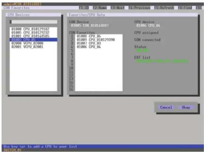
text_image
admin@CON_010148837 CON Favorites F1:ID F2:Name F3:Next F4:Previous F5:Refresh F6:Find ESC CPU Devices 01000 CPU_010129182 01005 CPU_010129232 01001 CPU_010148585 01001 CPU_05 02000 VCPU_02000 02001 VCPU_02001 Favorites/CPU Data CON_Device 0900S CON_010148887 CON_Favorites 1 01008 CPU_06 2 01009 CPU_010129390 3 01007 CPU_03 4 01006 CPU_04 5 6 7 8 9 10 11 12 13 14 15 16 CPU_device 01006 CPU_04 CPU assigned CON connected Status EXT list Cancel Okay Use key to add a CPU to your list SWITCH 01FIGURE 4-45. ASSIGNMENTS—CON FAVORITES
To create a favorite list for your own console, proceed as follows:
- Select a CPU to be moved to the favorite list on the CPU Devices list. Press to move a CPU Device to the favorite list. Press
to remove a CPU from the favorite list. - The order of the CPU devices within the favorite list can be changed by pressing <+> and <->.
- Press the Save button to save the settings.
CHAPTER 4: CONFIGURATION
NEED HELP? LE AVE THE TECH TO US
LIVE 24/7 TECHNICAL SUPPORT
1.87 7.87 7.226 9
JAVA TOOL
♦ Select the user in the working area of the CON Devices menu for the favorite list and open the Favorites tab.
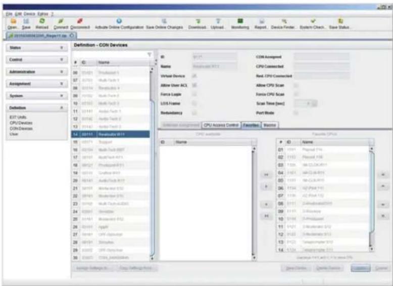
text_image
COM - COM Devices Definition - COM Devices Status Control Administration Assignment System Definition EET Units CPU/Devices COM Devices User 01 02 03 04 05 06 07 08 09 10 11 12 13 14 15 16 17 18 19 20 21 22 23 24 25 26 27 28 29 30 31 32 33 34 35 36 37 38 39 40 41 42 43 44 45 46 47 48 49 50 51 52 53 54 55 56 57 58 59 60 61 62 63 64 65 66 67 68 69 70 71 72 73 74 75 76 77 78 79 80 81 82 83 84 85 86 87 88 89 90 91 92 93 94 95 96 97 98 99 00 01 02 03 04 05 06 07 08 09 10 11 12 13 14 15 16 17 18 19 20 21 22 23 24 25 26 27 28 29 30 31 32 33 34 35 36 37 38 39 40 41 42 43 44 45 46 47 48 49 50 51 52 53 54 55 56 57 58 59 60 61 62 63 64 65 66 67 68 69 70 71 72 73 74 75 76 77 78 79 80 81 82 83 84 85 86 87 88 89 90 91 92 93 94 95 96 97 98 99 100FIGURE 4-46. DEFINITION—CON DEVICES
To create a favorite list for any console, proceed as follows:
- Select the CPUs in the CPU available list that should be added to the favorite list (CPU assigned). At the same time, multiple CPU Devices can be marked by pressing and holding
. - Press the > button to move the marked CPU Devices to the favorite list. If you press the >> button, the first eight CPU Devices from the list will be moved to the favorite list (CPU assigned).
- To change the order of marked CPU Devices within the favorite list, press <+> and <->.
- To remove marked CPU Devices from the favorite list, press the < button. If you press the << button, all CPU Devices will be removed from the favorite list.
CHAPTER 4: CONFIGURATION
4.11.5 CONSOLE MACROS
In this menu, macro commands for switching, disconnection or user administration can be created. The macro commands are created for each console separately.
A macro can execute up to 16 switching commands successively.
The execution of the macros is done via hotkey and the function keys
You can select the following settings.
TABLE 4-43. CONSOLE MACROS SETTINGS
| FIELD SELECTION DESCRIPTION | ||
| Function (01-16) | Connect(P1=CON, P2=CPU) | Set bidirectional connection from console P1 to CPU P2 |
| Connect Video(P1=CON, P2=CPU) | Set video connection from console P1 to CPU P2 | |
| Disconnect (P1=CON) Disconnect console P1 | ||
| Logout User Logout current user | ||
| Set Real CPU(P1=VCPU, P2=RCPU) | Assign a virtual CPU to a real CPU | |
| Set Virtual CON(P1=RCON, P2=VCON) | Assign a real console to a virtual console | |
| Push (P1=CON) | The user's KVM connection is forwarded to console P1 and is changed to a video only connection. | |
| Push Video (P1=CON) | The video signal of the current connection (KVM or video only) is forwarded to console P1. The user's connection remains unchanged (KVM or video only). | |
| Get (P1=CON) | The console gets a KVM connection to the CPU that is currently connected to console P1. The connection of console P1 is changed into a video only connection. | |
| Get Video (P1=CON) | The console gets a video only connection to the CPU that is currently connected to console P1. The connection of console P1 remains unchanged (KVM or video only). | |
| Login User Login a certain user P1 at console P2 | ||
| P1 CON or CPU Device Name of CON or CPU Device | ||
| P2 | CPU or CPU Device | Name of CPU or CPU Device |
You have the following options to access the menu.


CHAPTER 4: CONFIGURATION
NEED HELP? LE AVE THE TECH TO US
LIVE 24/7 TECHNICAL SUPPORT
1.87 7.87 7.22 6 9
OSD
- Select via Configuration > CON Macros in the main menu the console for which a console macro is to be created.

text_image
03000 CON_010125349 - admin Configuration F1:10 F2:Name F3:Next F4:Previous F5:Refresh F6:Find ESC CON devices 03000 CON_010125349 CON Macros Key : F01 Parameter #1 Parameter #2 Connect 03000 CON_010125349 01001 CPU_010135060 Disconnect 03000 CON_010125349 Macro Data Function CON Devices not used Disconnect Actual CON device Parameter #1 03000 CON_010125349 Parameter #2 Edit Delete Save Switch 01FIGURE 4-47. CONFIGURATION—CON MACROS
To create a macro for the selected console, proceed as follows:
- Select in the Key field the function key (F1-F16) for which a macro should be created.
- Select the respective place on the list (1-16) the key that should be set with a macro key.
- Select for the highlighted position on the list a macro command in the Macro Data field.
- Set the necessary parameters P1 and P2 (e.g. CON Devices or CPU Devices) for the selected macro command.
- Confirm your inputs by pressing
and repeat the process for further macro commands, if necessary.
CHAPTER 4: CONFIGURATION
JAVA TOOL
- Select the console in the working area of the Definition > CON Devices menu for which a macro has to be created and open the Macros lab.

text_image
COM Device Options Start - Save Forward Connect Document Activate Online Configuration Save Online Changes Download Upload Monitoring Report Device Provider System Options... Save Status Definition - COM Devices Status Control Administration Assignment System Definition EXT Units CPU Devices COM Devices User ID Name 01 02 03 04 05 06 07 08 09 10 11 12 13 14 15 16 17 18 19 20 21 22 23 24 25 26 27 28 29 30 31 32 33 34 35 36 37 38 39 40 41 42 43 44 45 46 47 48 49 50 51 52 53 54 55 56 57 58 59 60 61 62 63 64 65 66 67 68 69 70 71 72 73 74 75 76 77 78 79 80 81 82 83 84 85 86 87 88 89 90 91 92 93 94 95 96 97 98 99 100 Key: P1 Function: P1 P2 Connect P1@COM, P2@CPU: P2@COM: 1: 2012 (OP-PC-16) Connect P2@COM, P2@CPU: P2@COM: 2: 2012 (OP-PC-15) Connect P2@COM, P2@CPU: P2@COM: 3: 2012 (OP-PC-14) Connect P2@COM, P2@CPU: P2@COM: 4: 2012 (OP-PC-13) Connections: P1 Cancel: Cancel: Cancel:FIGURE 4-48. DEFINITION—CON DEVICES
To create a macro for the selected console, proceed as follows:
- Select in the Key field the function key (F1-F16) for which a macro has to be created.
- Select in the Function column the commands that should be part of the macro. The selection list will be opened by a double-click on the empty fields.
- Select the respective parameters for the macro functions (e.g. corresponding consoles and CPUs) in the P1 and P2 columns.
- Confirm your inputs by pressing the Apply button.
For an efficient macro configuration, the following context functions are available:
When clicking on the Macros tab, macros can be assigned to other consoles by using the Assign Macros to ... function and can be copied from other consoles by using the Copy Macros from ... function.
- When clicking on the macro list, macros of the selected key can be copied into the cache by using the Copy Key Macros function. You can paste the macros from the cache into a key by using the Paste Key Macros function and you can reset all macros of the selected key by using the Reset Key Macros function.
CHAPTER 4: CONFIGURATION
This menu enables shared operation of a CPU Device by two or more CON Devices. A CPU Device can be controlled by only one CON Device at a time but can be taken over successively by other CON Devices. Control of a CPU Unit by a CON Unit is relinquished after the expiration of an inactivity timer associated with the controlling CON Device. The mouse or keyboard may also be used to take control.
To allow a smooth and accurate function of the shared operation, you should use identical mice and keyboards.
They should be connected to the same USB-HID ports of each CON Unit.
The alternative is using USB-HID Ghosting (see Section 5.11).
When taking over control within 10 seconds, any assigned USB 2.0 / 3.0 extenders, if available, will not be switched because of security and stability aspects.
You have the following options to configure shared operation.


OSD
- Select via Configuration > Switch in the main menu.
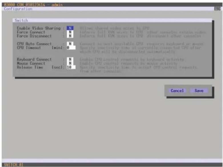
text_image
03008 CON 010123614 -- admin Configuration ESC Switch Enable Video Sharing : N Force Connect : N Force Disconnect : N CPU Auto Connect : N CPU Timeout [min] : 0 Keyboard Connect : N Mouse Connect : N Release Time [sec] : 10 8) Now shared video access to CPU. Inferes full XVM access to CPU other comments, retain video. Inferes full XVM access to CPU distinguished other comments Connect to next available CPU resources explored or more. Specify effectively time at currently completed CPU after which CPU will be disconnected automatically Enable CPU control requests by onboard activity. Enable CPU control requests by mouse activity. Specify effectively time to accept CPU control requests. From other comments. Cancel Save SHUTCH 01FIGURE 4-49. CONFIGURATION-SWITCH
CHAPTER 4: CONFIGURATION
NEED HELP? LE AVE THE TECH TO US
LIVE 24/7 TECHNICAL SUPPORT
1.8 7 7.8 77.2 26 9
To configure shared operation, proceed as follows:
- Activate the Enable Video Sharing function.
- Activate the Force Connect function.
- Activate the Keyboard Connect function, if taking over control by a keyboard event should be possible.
- Activate the Mouse Connect function, if taking over control by a keyboard movement should be possible.
- Define a Release Time of inactivity (0–999 sec.) after which control can be taken over.
JAVA TOOL
- Select via System > Switch in the task area.

text_image
File Edit Device Options Open Save Reload Connect Clear/Activate Online Configuration Save Online Changes Download Upload Monitoring Report Device Finder System Check Save Status System - Switch Switch Settings Enable Video Sharing Index shared index accessed to CPU Force Connect Enclose NVIDIA access to CPU, other computer read value Force Disconnect Enclose NVIDIA access to CPU, other computer are recommended CPU Auto Connect Connect to next available CPU, alternative broadband or remote CPU Temporal [msx] Specify connectivity: percent at currently connected (CPC) after which (CPC) will be disconnected automatically (if = downloaded) Keyboard Connect Enable (CPC) control requested by keyboard activity Mouse Connect Enable (CPC) control requested by mouse activity Release Time [set2] Specify connectivity that is accepted (CPC) comes requested from another occurrence Show Help Config rebootedFIGURE 4-50. SYSTEM-SWITCH
To configure shared operation, proceed as follows:
- Activate the Enable Video Sharing function.
- Activate the Force Connect function.
- Activate the Keyboard Connect function, if taking over control by a keyboard event is to be permitted.
- Activate the Mouse Connect function, if taking over control by a keyboard movement should be possible.
- Define a Release Time of inactivity (0 - 999 sec.) after which control can be taken over.
CHAPTER 4: CONFIGURATION
4.11.7 MULTI-SCREEN CONTROL
This menu configures the USB-HID switching operation, allowing a CON Device with several monitors to control several connected sources (computers, CPUs). Smooth switching can be performed for up to four connected sources by dragging the mouse pointer beyond the respective monitor to an adjacent one.
Monitors can be arranged side-by-side or in a grid layout.
CAUTION: When using sources (computers, CPUs) in multi-head operation (e.g. dual-head), switching only works manually via keyboard commands. Noncompliance may have a negative influence on the stability of the system.
When using CON Units with the possibility to connect a local source (computer, CPU) in a Multi-Screen Control environment, the local switching will be disabled.
NOTE: To enable Multi-Screen Control, all Extender Units assigned to the related CON Device, must be physically connected to the same block of 4 ports on the I/O board of the matrix.
CON Units that have been already configured for Multi-Screen Control can be connected together to other blocks of 4 ports. In this case, any further configuration is not necessary; their functionality will remain as set previously.
You have the following options to access the menu.


CHAPTER 4: CONFIGURATION
NEED HELP? LE AVE THE TECH TO US
LIVE 24/7 TECHNICAL SUPPORT
1.87 7.87 7.226 9
OSD
- Select Assignments > Multi-Screen Control in the main menu.

text_image
adminPCON 010125349 Multi-Screen Control ESC Arrangement • Switching Screens : 1 x 4 Manual : N Done with four screens or less goes with the screens web Reduce switching to manual selections with helixes Disable automatic selection with name for wholehead Dtb Screen #1 CON_010125349 Enabled : V Control : N Owner : shared Frame : 0 SEC Screen #2 screen not available Enabled : N Control : N Owner : SEC Frame : SEC Screen #3 screen not available Enabled : N Control : N Owner : SEC Frame : SEC Screen #4 screen not available Enabled : N Control : N Owner : SEC Frame : SEC Cancel Okay SWITCH #1FIGURE 4-51. ASSIGNMENTS—MULTI-SCREEN CONTROL
To configure the Multi-Screen Control, proceed as follows:
- In the Arrangement field, select the layout for the CON Device you want to configure (1 x 4 or 2 x 2). The fields for the configuration of the individual displays will be arranged accordingly.
- Activate Manual option, if USB-HID switching is to be restricted to keyboard commands (see Section 5.6). Manual switching allows the use of multi-head consoles.
- Ensure that the Enabled option is set to Y on all displays in order to activate the respective display for Multi-Screen Control.
- Select one or more control displays within the CON Device by setting the Control function to Y in the display field. Control displays are referred to the extender units within the Multi-Screen Control that are connected to keyboard and mouse.
- When using the Owner function, you can determine which control display is permitted for USB-HID switching to the different displays. Select that display from the list. To make a display accessible to all neighboring control displays, set the Owner function to shared.
- Use the Frame function to configure a red frame that shows the current display with mouse control after the expiration of a selectable timer. The frame to fade in can be individually activated by using a timer >0 seconds.
CHAPTER 4: CONFIGURATION
JAVA TOOL
- Select Assignment > Multi-Screen Control in the task area.
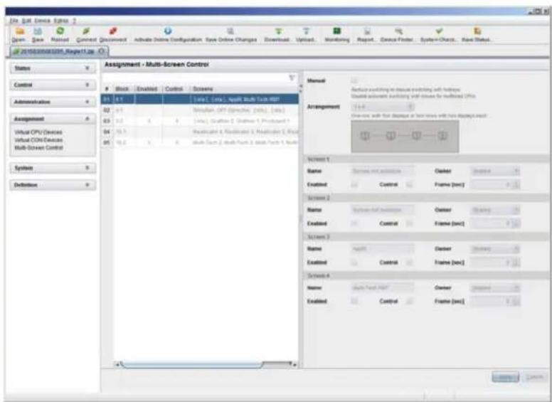
text_image
File Edit Device Options 2 Drawn Save Rated Correct Document Active Online Configuration Save Online Changes Download Upload Monitoring Report Device Finder System Check Real Status 2016/03/2016/03/2016/03/2016/03/2016/03/2016/03/2016/03/2016/03/2016/03/2016/03/2016/03/2016/03/2016/03/2017 Assignment - Multi-Screen Control Status Control Administration Assignment Virtual CPV Devices Virtual COM Devices Mult-Screen Control System Definition Assignment - Multi-Screen Control Block -Enabled Control Screens 01 0.7 [sys1, [sys], split Multi Tech HSD] 02 4.1 Simulation OPT Directive (sys1, [sys]) 03 5.2 [sys1, Gathion 1, Gathion 1, Protagard 1] 04 5.3 Reconstructed & Reconstructed & Reconstructed 1, Real 05 5.4 Multi Span 2 Multi Span 3 Multi Span 4, Real Manual Arrangement Name Training and Extension Builder Enabled Control Frame (sec) Screen 1 Name Training and Extension Builder Enabled Control Frame (sec) Screen 2 Name Training and Extension Builder Enabled Control Frame (sec) Screen 3 Name Training Builder Enabled Control Frame (sec) Screen 4 Name Multi Span HSD Builder Enabled Control Frame (sec) 确定 CancelFIGURE 4-52. ASSIGNMENTS—MULTI-SCREEN CONTROL
To configure the Multi-Screen Control, proceed as follows:
- Select the block of four ports in the list of the working area that should be configured for Multi-Screen Control. Only blocks of four ports that contain at least one CON Unit are shown.
- Activate Manual option, if the USB-HID switching is to be restricted to keyboard commands (see Section 5.6). Manual switching allows the use of multi-head consoles.
- In the Arrangement field, select the layout for the CON Devices you want to configure (1 x 4 or 2 x 2). The fields for the configuration of the individual displays will be arranged accordingly.
- Select one or more control displays within the CON Device by setting the Control function to Y in the respective display field. Control displays are referred to the extender units within the Multi-Screen Control that are connected to keyboard and mouse.
- When using the Owner function, you can determine which control display is permitted for USB-HID switching to the different displays. Select that display from the list. To make a display accessible for all neighboring control displays, set the Owner function to shared.
- Use the Frame function to configure a red frame that shows the current display with mouse control after the expiration of a selectable timer. The frame to fade-in can be individually activated by using a timer >0 seconds.
4.12 SAVING AND LOADING CONFIGURATIONS
You have the option to set the following administration of configurations.
4.12.1 ACTIVE CONFIGURATION
You have the following option to access the menu.

- Select Configuration > Save in the main menu.
By selecting this menu item, the active configuration of the matrix is saved to the permanent matrix memory. By default, the last configuration that has been saved in this way will be restored after a restart of the matrix.
NOTE: Changing or saving configurations blocks the matrix memory and leads to a freeze of all OSD menus for a few seconds.
The switching connections are not affected by this freeze.
If you select Auto Save within the system settings, an additional automatic saving of the configuration will be periodically performed (see Secton 4.3.2).
4.12.2 SAVING CONFIGURATION (INTERNAL)
In this menu, the current matrix configuration is saved to predefined storage locations. However, it does not replace the buffering of configuration (see Section 4.12.1).
You have the following options to access the menu.


In Active, the name and detailed information of the current configuration are shown. This configuration can be saved.
In Default and File #1 to File #8, the name and detailed information of the respective saved configuration are shown. These storage locations can be overwritten.
The storage location to be overwritten by the current configuration must be selected explicitly.
The current configuration will be saved to this storage location and will be shown immediately in the menu. The previously saved configuration saved to this storage location is deleted.
CHAPTER 4: CONFIGURATION
NEED HELP? LE AVE THE TECH TO US
LIVE 24/7 TECHNICAL SUPPORT
1.8 7 7.87 7.2269
OSD
You have the possibility to save the created configuration within eight storage locations in the matrix (File #1 - File #8). Additionally, a configuration can also be saved as default configuration.
-
Select Configuration > Save As... in the main menu.
-
Select the required storage location (File #1 - File #8) or Default.

text_image
03000 0701 010123614 - admin Configuration Save as... Active : Default File #1 File #2 File #3 File #4 File #5 File #6 File #7 File #8FIGURE 4-53. CONFIGURATION—SAVE AS
JAVA TOOL
- Select via Assignment > Multi-Screen Control in the task area.
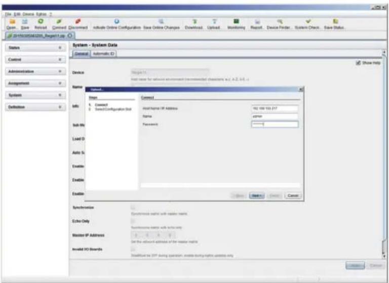
text_image
System - System Data General Automatic ID Device Name Connect 1. Connect 2. Select Configuration Sub Host Name: IP Address 902 100 100 117 Name 24766 Password Sub-Me Load D Auto S Enable Enable Enable Syncerionix Echo Only Master IP Address Set the relevant address of the reader matrix Enable ISO Boards Select the TCP during operation, create using a data source only Show HelpFIGURE 4-54. FILE—UPLOAD
CHAPTER 4: CONFIGURATION
NEED HELP? LE AVE THE TECH TO US
LIVE 24/7 TECHNICAL SUPPORT
1.877.877.2269
4.12.3 LOADING CONFIGURATION (INTERNAL)
Previously saved configurations are loaded in this menu.
You have the following options to load configurations from files.

text_image
OSD JAVAIn Active, the currently loaded configuration is displayed.
In addition to the default configuration, up to eight further configurations can be loaded.
The selection of the configuration to be loaded can be made between eight personalizable configurations and the default settings.
The selected configuration is immediately loaded and displayed in the menu as Active. The previously active configuration is deleted.
OSD
- Select Configuration > Open in the main menu.
- Select the desired configuration.
- Load the configuration by pressing
.
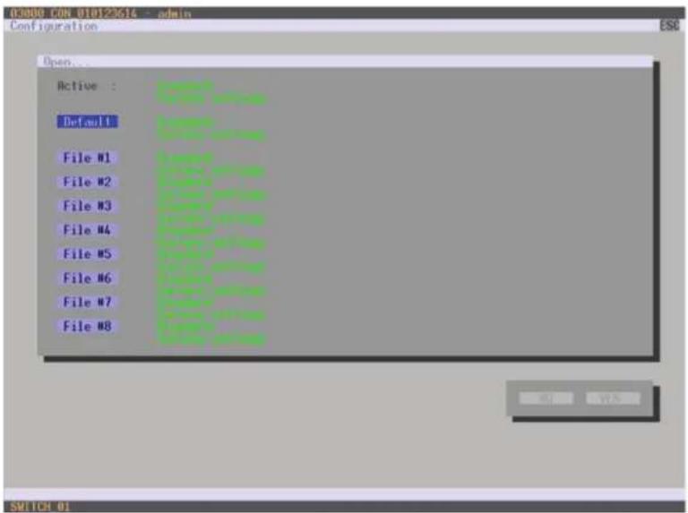
text_image
03000 CEN 010123614 admin Configuration Open... Active : Default File #1 File #2 File #3 File #4 File #5 File #6 File #7 File #8FIGURE 4-55. CONFIGURATION—OPEN
CHAPTER 4: CONFIGURATION
NEED HELP? LE AVE THE TECH TO US
LIVE 24/7 TECHNICAL SUPPORT
1.877.877.2269
JAVA TOOL
- Select Administration > Activate Configuration during online mode in the task area.
- Select the desired configuration.
- Load the configuration by pressing the Activate button.
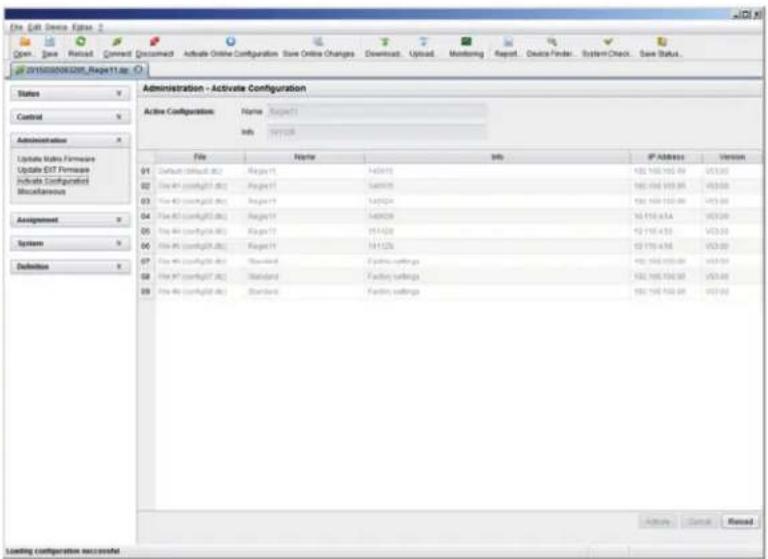
text_image
File Edit Device Options 2 Open Save Reset Next Document Activate Online Configuration Save Online Changes Download Upload Monitoring Report Device Finder System Check Save Status... 0110300000000000000000000000000000000000000000000000000000000000000000000000000000000 Administration - Activate Configuration Active Configuration Name Target1 Info: 997268 File Name Info IP Address Version Default (default) No. Range 14/24/25 182 182 182 99 V33.69 File No (config)(1) No. Range 14/24/25 182 182 182 99 V33.69 File No (config)(2) No. Range 14/24/25 182 182 182 99 V33.69 File No (config)(3) No. Range 14/24/25 182 182 182 99 V33.69 File No (config)(4) No. Range 14/24/25 182 182 182 99 V33.69 File No (config)(5) No. Range 14/24/25 182 182 182 99 V33.69 File No (config)(6) No. Range 14/24/25 182 182 182 99 V33.69 File No (config)(7) No. Range 14/24/25 182 182 182 99 V33.69 File No (config)(8) No. Range 14/24/25 182 182 182 99 V33.69 Loading configuration successful Active Cancel ResetFIGURE 4-56. ADMINISTRATION—ACTIVATE CONFIGURATION
4.12.4 SAVING CONFIGURATIONS (EXTERNAL)
Configurations can be saved as files that can be stored independent of the matrix.
You have the following option to access the menu.

- Select File > Save As in the menu bar.
- Enter a name for the configuration.
- Select the directory of the configuration on your storage medium where it is to be saved.
NOTE: Configurations are always saved in a file with the ending dtc.
CHAPTER 4: CONFIGURATION
NEED HELP? LE AVE THE TECH TO US
LIVE 24/7 TECHNICAL SUPPORT
1.877.877.2269
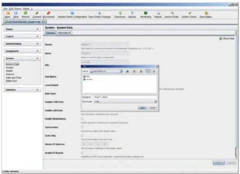
text_image
File Edit Device Options 2 Open... Save Recancel Connect Document Activate Online Configuration Save Online Changes Download... Upload... Monitoring Report... Device Finder... System Check... Save Status... GO /\SYSTEM\system\Request\Lab System - System Data General Automatic ID Show Help Device Name Info Sub Matrix: Load Default Auto Save Enable COM Echo Enable LAB Echo Enable Redundancy Syncronvise Echo Only Monitor IP Address Install IO Board MakeUp or IPT during session, enable running remote progress via if all the attempts achieved Get up to action comments on Lab groups Enable automatic triggering for continued sessions Syncronvise rights with remote wins. Syncronvise rights with active win Set the network addresses of the master team's Install IO Board InstallUp or IPT during session, enable running remote progress via CancelFIGURE 4-57. FILE—SAVE AS
4.12.5 LOADING CONFIGURATIONS (EXTERNAL)
Externally saved configurations are opened and activated in this menu.
You have the following option to load configurations from files.

- Select File > Open... during offline mode and select the storage location of the configuration file that has to be opened.
- Open the configuration by pressing the Open button.
- Select File > Upload in the menu bar to transfer the opened configuration to the matrix. Enter the necessary parameters.
- Select Matrix > Connect in the menu bar to make a connection between the matrix and the Java tool. Enter the necessary parameters.
- Select Administration > Activate Configuration and select the configuration to be activated.
- Confirm the process with the Activate button.
The opened configuration is activated.
CHAPTER 4: CONFIGURATION
NEED HELP? LE AVE THE TECH TO US
LIVE 24/7 TECHNICAL SUPPORT
1.8 7 7.87 7.2269
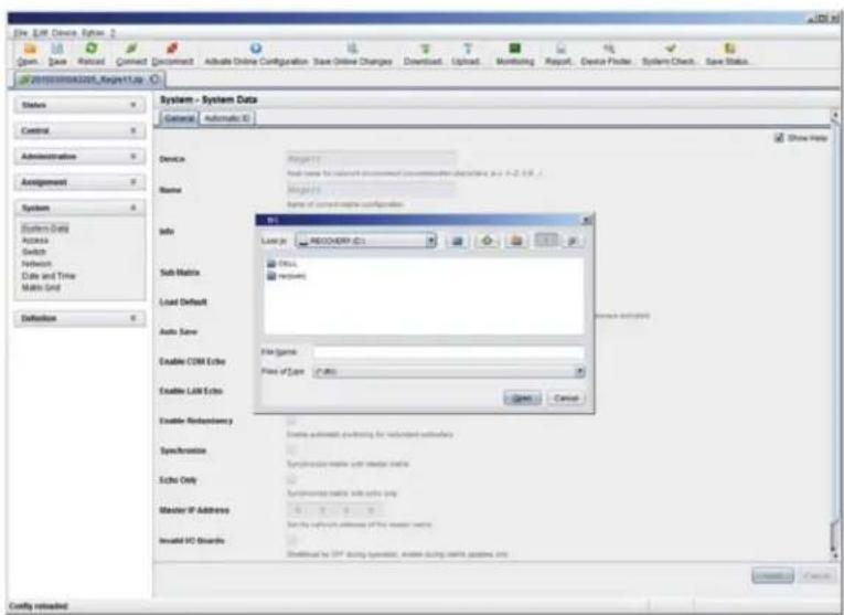
text_image
File Edit Device System 2 Open. Save Process Connect Document Active Online Configuration Save Online Changes Download Upload Monitoring Report Device Prefix System Check Save Status System - System Data Context Automatic ID Device Project1 Host name for network processing parameters configuration in p.4-2.0.1 Name Project1 Name of current data configuration Info Local jr RECOCORRY ID:1 Dots Executs Sub Matrix Load Default Auto Save File Game File of Type: IP365 Enable COM Echo Enable Lark Echo Cancel Enable Redoability Enable automatic filtering for randomized networks Syncronics Syncronics matrix with master mode Echo Only Syncronics matrix with echo key Master IP Address Set the network address of the master mode. Invalid ISO Boards Default to LP* during operation, create during matrix passes into Configure reloadedFIGURE 4-58. FILE-OPEN
4.13 EXPORT AND IMPORT OPTIONS
The Compact KVM Matrix Switch offers the ability to read out available configuration lists (extender, CPUs, consoles and users) for export and import again via Java tool. You have the following option to handle configuration lists.
Exported configuration lists are always saved in .csv format that allows offline editing with common spreadsheet applications.
You have the following option to export or import configuration lists:

4.13.1 EXPORT OPTIONS
Configuration lists are exported in this menu. In order to export, proceed as follows:
- Select File > Export in the menu bar.
- After opening the menu, select the list to export (Extender, CPU, Console or User).
- Select the storage location for the export file.
- Confirm the export with the Finish button.
CHAPTER 4: CONFIGURATION
NEED HELP? LE AVE THE TECH TO US
LIVE 24/7 TECHNICAL SUPPORT
1.8 77.8 77.2 26 9

text_image
File Edit Device Options Open Save Next Reset Connect Document Annulate Online Configuration Save Online Changes Download Upload Monitoring Request Data Finder System Check Save Status 2016-03-2020/03_Report data System - System Data Commerce Automatic ID Show Help Device Name Export... Steps Select Type 1. Select Type 2. Export Configuration to Ctrl+Fix Sub Matrix Extractor CPU Console User Load Default Auto Save Enable COM Echo Enable LAK Echo Enable Randomistic Options Next > Back Cancel Cancel Syncronics Syncronics lists with reader details Extra Only Syncronics lists with auto-reds Marker IP Address 4.4.4.8 Define network address of the local matrix Install IO Boards Install as (PT) being chosen, enable using matrix suitable only Config installedFIGURE 4-59. FILE-EXPORT
4.13.2 IMPORT OPTIONS
Configuration lists are imported in this menu. To import, proceed as follows:
- Select File > Import in the menu bar of an offline configuration.
- After opening the menu, select the list to import (Extender, CPU, Console or User).
- Select the directory of the list to import.
- Confirm the import with the Finish button.
NOTE: Importing configuration lists is only possible in offline configurations.
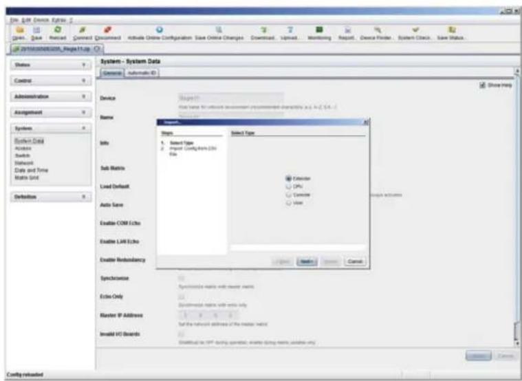
text_image
System - System Data General Automatic ID Device Name Type Select Type 1. Select Type 2. import Comptnion 0.05 File Sub Matrix Encoder CPU Controller View Load Default Auto Save Enable COM Echo Enable LAR Echo Enable Redundancy Syncrance Systeresize matrix with master matrix Echo Only Experimental matrix with row info Master IP Address Set the network address of the master matrix Insolid IO Board Default to CPN during operation, shift during matrix, update only System-System-Computer-Computer-Computer-Computer-Computer-Computer-Computer-Computer-Computer-Computer-Computer-Computer-Computer-Computer-Computer-Computer-Computer-Computer-Computer-Computer-Computer-Computer-Computer-Computer-Computer-Computer-Computer-Computer-Computer-Computer-Computer-Computer-Computer-Computer-Computer-Computer-Computer-Computer-Computer-Computer-Computer-Computer-Computer-Computer-Computer-Computer-Computer-Computer-Computer-Computer-PCN System - System Data Command Automatic ID System - System Data Command Automatic ID System - System Data Command Automatic ID System - System Data Command Automatic ID System - System Data Command Automatic ID System - System Data Command Automatic ID System - System Data Command Automatic ID System - System Data Command Automatic ID System - System Data Command Automatic ID System - System Data Command Automatic ID System - System Data Command AutomaticIDFIGURE 4-60. FILE-IMPORT
CHAPTER 4: CONFIGURATION
4.14 MATRIX CASCADING
This simple method of cascading allows a switchable connection between two matrices via Tie Lines.
The Matrix Cascading does not require Bundle 4.
This kind of configuration may become necessary if the number of ports in the entire system has to be increased or if certain important connections should be distributed to several matrices because of redundancy.
The Tie Lines are unidirectional and can only be used in one direction according to their configuration. For bidirectional use of cascading, you have to configure opposite Tie Lines.
To connect Tie Lines to the matrices, you have to create intended Master/Slave CON and Master/Slave CPU Devices that have to be switched within the cascaded environment.
You have the following options to configure Matrix Cascading:

text_image
OSD JAVAGENERAL PREPARATION
- Define a Master Matrix. All further matrices will be configured as Sub Matrices in the configuration process.
- Ensure that the Tie Lines will only be connected after finishing the configuration.
OSD
- Select Configuration >EXT Units in the main menu of the master matrix.

text_image
admin:CCON_010167832 Configuration F1:10 F2:Name F3:Next F4:Previous S:Refresh F5:Find ESC EXI Units 010195668 EXT 010135668 010167832 EXT_010167832 010203247 EXT_010203247 010207794 EXT_010207794 016090105 EXT_016090105 040011492 EXT_040011492 EXI Data ID : 10135668 CPU/CON assigned Name : EXI_010135668 0100S CPU_010207794 Fixed : N Port 1/2 : I A Universal : N General OSD Data Horizontal mouse speed [I/I]: A Vertical mouse speed [I/I]: S Double click time [sec]: 200 Keyboard layout : German DE.129 Video mode : variable Extender OSD Data Enable CPU selection : N Enable connection info : N Update connection info : N Display time [sec]: 0 Horizontal position : U Vertical position : U EXT Type Input Signals C#1 C#2 Output Signals C#1 C#2 DVI/VGA-CPU (video ..) V N DVI/VGA-CON (video ..) H N HID-CON (keyb.. mouse ..) N N HID-CPU (keyb.. mouse ..) V N Audio (analog, digital) N N Audio (analog, digital) H N RS232 (serial ..) N N RS232 (serial ..) N USB-CON (embedded) N N USB-CPU (embedded) H N USB-CON (standalone) N N USB-CPU (standalone) H N Universal-CON N N Universal-CPU H N Cascade-CON H N Cascade-CPU H N Switch OKFIGURE 4-61. CONFIGURATION—EXT UNITS
CHAPTER 4: CONFIGURATION
- Press the New button. A new Extender Unit will be created that is needed for the connection of Tie Lines.
- Enter an appropriate extender name into the Name field.
- Enter a port number into the Port field according to the required connection of the Tie Line.
- If the Tie Line should be directed from the Sub to the Master, set the Cascade-CON option to Y (C#1) in the Input Signals column. If the Tie Line should be directed from the Master to the Sub, set the Cascade-CPU option to Y (C#1) in the Output Signals column.
- Save your settings by pressing the Okay button.
- If you have created a Master/Slave CON Unit, select Configuration > CON Devices in the main menu of the master matrix and press the New R button. A switchable CON Device will be created.
- If you have created a Master/Slave CPU Unit, select Configuration > CPU Devices in the main menu of the master matrix and press the New R button. A switchable CPU Device will be created.
- Enter an appropriate Device name into the Name field.
- Assign the previously configured Extender Unit to the just created Device by moving the Extender Unit from the Ext available field into the Ext assigned field and save your settings.
- Repeat steps 1 to 9 for the Sub Matrix.
- Select Configuration > System in the main menu of the Sub Matrix and set the Sub Matrix option to Y.
The OSD of the Sub Matrix will immediately freeze and will be only accessible by using the keyboard command, ,. - Restart all I/O boards on which any Master/Slave CON or CPU Units have been configured or alternatively restart the matrix.
- Connect the Tie Lines to the matrices. Ensure that each Master/Slave CON on one matrix is connected to Master/Slave CPU on the other matrix to achieve switchability between two matrices.
The Matrix Casacading is now configured and can be used. Additional Tie Lines are configured accordingly. The use of cascading is described in Section 5.1.4.
JAVA TOOL
- Connect to the Master Matrix and activate the Online Configuration Mode.
- Select the menu Definition > EXT Units in the task area and press the New button. A popup window opens.

text_image
File Edit Device Options 2 Open, Save, Retired, Connect, Connect, Activate Online Configuration Save Online Changes Downloads Upload, Monitoring Report, Device Finder, System Check, Save Status... © 2019/03/06/2019_Report1.htm Status Control Administration Assignment Systems Definition EKT Units CPU Devens OSI Devens User Definition - EXT Units ID Name CPU Assigned Type CPU Assigned Name CPU Assigned Type CPU Assigned Name CPU Assigned Name CPU Assigned Name CPU Assigned Name CPU Assigned Name CPU Assigned Name CPU Assigned Name CPU Assigned Name CPU Assigned Name CPU Assigned Name CPU Assigned Name CPU Assigned Name CPU Assigned Name CPU Assigned Name CPU Assigned Name CPU Assigned Name CPU Assigned Name CPU Assigned Name CPU Assigned Name CPU Assigned Name CPU Assigned None CNC10000000000000000000000000000000000000000000000000000000000000000000000000000000000000000000000000000ID
Name Prtt Type B1: B1B2B4B4B4B4B4B4B4B4B4B4B4B4B4B4B4B4B4B4B4B4B4B4B4B4B4B4B4B4B4B4B4B4B4B4B4B4B4B4B4B4B4B4B4B4B4B4B4B4B4B4B8A1A1A1A1A1A1A1A1A1A1A1A1A1A1A1A1A1A1A1A1A1A1A1A1A1A1A1A1A1A1A1A1A1A1A1A1A1A1A1A1A1A1A1A1A1A1A1A1A1A1A2A2A2A2A2A2A2A2A2A2A2A2A2A2A2A2A2A2A2A2A2A2A2A2A2A2A2A2A2A2A2A2A2A2A2A2A2A2A2A2A2A2A2A2A2A2A2A2A2A2A3D3D3D3D3D3D3D3D3D3D3D3D3D3D3D3D3D3D3D3D3D3D3D3D3D3D3D3D3D3D3D3D3D3D3D3D3D3D3D3D3D3D3D3D3D3D3D3D3D3D3C5C5C5C5C5C5C5C5C5C5C5C5C5C5C5C5C5C5C5C5C5C5C5C5C5C5C5C5C5C5C5C5C5C5C5C5C5C5C5C5C5C5C5C5C5C5C5C5C5C5C7E7E7E7E7E7E7E7E7E7E7E7E7E7E7E7E7E7E7E7E7E7E7E7E7E7E7E7E7E7E7E7E7E7E7E7E7E7E7E7E7E7E7E7E7E7E7E7E7E7E7F8F8F8F8F8F8F8F8F8F8F8F8F8F8F8F8F8F8F8F8F8F8F8F8F8F8F8F8F8F8F8F8F8F8F8F8F8F8F8F8F8F8F8F8F8F8F8F8F8F8F6G6G6G6G6G6G6G6G6G6G6G6G6G6G6G6G6G6G6G6G6G6G6G6G6G6G6G6G6G6G6G6G6G6G6G6G6G6G6G6G6G6G6G6G6G6G6G6G6G6G6 G6G6G6G6G6G6G6G6G6G6G6G6G6G6G6G6G6G6G6G6G6G6G6G6G6G6G6G6G6G6G6G6G6 G6 G6 G6 G6 G6 G6 G6 G6 G6 G6 G6 G6 G6 G6 G6 G6 G6 G6 G6 G6 G6 G6 G6 G6 G6 G6 G6 G6 G6 G6 G6 G6 G6 G6 G6 G6 G6 G6 G6 G6 G6 G6 G6 G6 G6 G6 G 8 A 8 B 8 C 8 D 8 E 8 F 8 G 8 H 8 I 8 J 8 K 8 L 8 M 8 N 8 O 8 P 8 Q 8 R 8 S 8 T 8 U 8 V 8 W 8 X 8 Y 8 Z 8 A 8 B 8 C 8 D 8 E 8 F 8 G 8 H 8 I 8 J 8 K 8 L 8 M 8 N 8 O 8 P 8 Q 8 R 8 S 8 T 8 U 8 V 8 W 8 X 8 Y 8 Z 8 A 8 B 8 C 8 D 8 E 8 F 8 GFIGURE 4-62. DEFINITION—EXT UNITS
CHAPTER 4: CONFIGURATION
- If the Tie Line should be directed from the Sub to the Master, select Master/Slave CON Unit in the Choose Extender Type selection box. If the Tie Line should be directed from the Sub to the Master, select Master/Slave CPU Unit in the Choose Extender Type selection box.
- Enter an appropriate extender name into the Name field.
- Enter a port number into the Port field according to the required connection of the Tie Line.
- Confirm your settings by pressing the Apply button.
- If you have created a Master/Slave CON Unit, select Definition > CON Devices in the task area of the master matrix and press the New button. A switchable CON Device will be created.
- If you have created a Master/Slave CPU Unit, select Definition > CPU Devices in the task area of the Master Matrix and press the New button. A switchable CPU Device will be created.
- Enter an appropriate extender name into the Name field.
- Assign the previously configured Extender Unit to the just created Device by moving the Extender Unit from the Extender available field into the Extender assigned field and save your settings by pressing the Apply button.
- Connect to the Sub Matrix and repeat steps 1 to 10.
- Select System > System Data in the task area of the Sub Matrix and activate the Sub Matrix option.
The OSD of the Sub Matrix will immediately freeze and will be only accessible by using the keyboard command, ,. - Restart all I/O boards on which any Master/Slave CON or CPU Units have been configured or alternatively restart the matrix.
- Connect the Tie Lines to the matrices. Ensure that each Master/Slave CON on one matrix is connected to Master/Slave CPU on the other matrix in order to achieve switchability between two matrices.
The Matrix Cascading is now configured and can be used. Additional Tie Lines are configured accordingly. The use of cascading is described in Section 5.1.4.
4.15 MATRIX GRID
In this menu, you can configure a Matrix Grid to connect two or more matrices. This kind of configuration may be necessary if the number of ports in the entire system has to be increased or if certain important connections should be distributed to several matrices because of redundancy.
The connections between two matrices have to be established by Grid Lines that are connected between particular I/O ports as connecting links. The Grid Lines can be used bidirectionally and can respectively handle a full access connection of a CON Device to a CPU Device.
The number of Grid Lines in the system specifies if a CON Device can be switched to a CPU Device in Non-Blocking Access or in Blocking Access and has to be separately determined for each Grid environment.
In this case, Non-Blocking Access means that a Grid Line for a cross-matrix switching operation of a CON Device to a CPU Device is available at any time.
Blocking Access means that for a certain switching operation no Grid Line may be available according to the switching status within the Grid. As a result, no cross-matrix switching will be possible.
CHAPTER 4: CONFIGURATION
NEED HELP? LE AVE THE TECH TO US
LIVE 24/7 TECHNICAL SUPPORT
1.8 77.8 77.2269
You have the following options to configure Matrix Grid:


ADMINISTRATION OF SETTINGS
Within a Matrix Grid, you have to differ between settings that have to be made locally for each matrix and settings that can be made globally so that they are valid for the whole Matrix Grid.
The settings in the following menus have to be made separately for each matrix or within the master matrix to affect all matrices in the Grid:
System, Access, Switch, Network, Date + Time, SNMP, Matrix Grid, Multi-Screen Control
The settings in the following menus have to be made globally and only once within the Matrix Grid:
EXT Units, CPU Devices, CON Devices, User, CON Macros, User Macros, CON Favorites, User Favorites, Virtual CPU Devices, Virtual CON Devices
NOTE: If global settings are made in the respective menus, they will be immediately available on each matrix within the Matrix Grid.
GENERAL PREPARATION
The following requirements have to be fulfilled before starting the Matrix Grid configuration:
- The Matrix Grid function (Bundle 4) must be activated on all matrices to be connected to the Grid by a license key (see Section 4.17).
- Firmware V03.10 must be installed on all matrices to be connected to the Grid.
- All matrices to be connected to the Grid must be within the same TCP/IP network (see Section 4.4.5).
- The port 5556 needed for network communication must not be blocked by a firewall.
CHAPTER 4: CONFIGURATION
NEED HELP? LE AVE THE TECH TO US
LIVE 24/7 TECHNICAL SUPPORT
1.8 77.8 77.2 26 9
OSD
To configure a Matrix Grid, proceed as follows. The following configuration steps have to be repeated for each matrix separately:
- Select Configuration > System in the main menu.
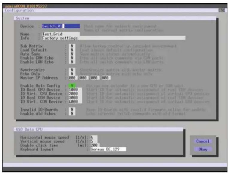
text_image
admiAICON 010195237 Configuration ESC System Device: Switch 01 Name: Test_Grid Info: Factory settings Sub Matrix: Load Default: Auto Save: Enable CON Echo: Enable CON Echo: Synchronize Echo Only: Master IP Address: Enable Auto Config: ID Real CPU Device: ID Virt CPU Device: ID Real CON Device: ID Virt CON Device: Invalid ID-Boards: Enable old Echoes: Do not switch the network environment. Name of external matrix configuration. Allow Hotkey control in cascaded measurement. Load always default configuration. Show matrix status automatically. Echo all click commands via CPU ports. Show all switch commands via LAN ports. Synchronize matrix with other matrices. Synchronize matrix with echo only. 800 000 000 000 Enable new extender to a new CPU or CPU slot. Start ID for automatic arrangement of real CPU devices. Start ID for automatic arrangement of virtual CPU devices. Start ID for automatic arrangement of real CPU devices. Start ID for automatic movement of virtual CPU devices. Even ID-Boards with modified hardware write for update else internal switch commands with aid format. OSO Data CPU Horizontal mouse speed [1/x]: 4 Vertical mouse speed [1/x]: 5 Double click time [ms]: 200 Keyboard layout : German DE.129 Cancel OkayFIGURE 4-63. CONFIGURATION—SYSTEM
- Enter a unique name for each matrix into the Device field. Each name only may exist once within the Matrix Grid.
- Enter a unique Grid name into the Name field. The Grid name has to be same within all Grid matrices.
- Select Configuration > Matrix Grid in the main menu.
CHAPTER 4: CONFIGURATION
NEED HELP? LE AVE THE TECH TO US
LIVE 24/7 TECHNICAL SUPPORT
1.8 77.8 77.2 26 9
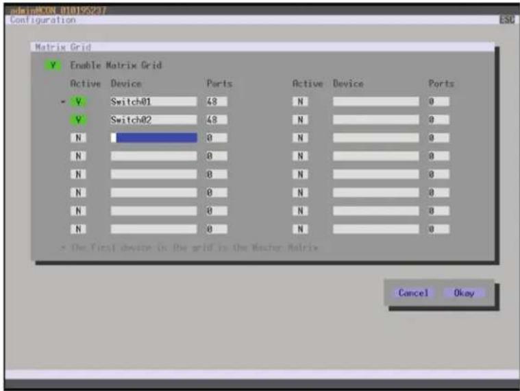
text_image
Matrix Grid Enable Matrix Grid Active Device Ports Active Device Ports V Switch01 48 N 0 V Switch02 48 N 0 N 0 N 0 N 0 N 0 N 0 N 0 N 0 N 0 N 0 N 0 N 0 N 0 * The first device in the grid is the Vector Matrix Cancel OkayFIGURE 4-64. CONFIGURATION—MATRIX GRID
- Activate the Enable Matrix Grid function.
- Write all device names of the Grid matrices into the Matrix Grid list, starting in the left column. Based on the listings, a Grid master will be automatically determined for the Matrix-Grid. The more on the top a matrix is listed in the matrix Grid list, the more likely the matrix is considered in the automatic master selection, provided that certain criteria like system availability are fulfilled.
- Activate the single matrices in the Matrix Grid list by enabling the Y (YES) function.
- Enter the number of chassis ports for each matrix (8, 16, 32, 48, 64, 80, 160 or 288).
- Restart all matrices, beginning with the master matrix.
The Matrix Grid can be used now and offers the possibility for a cross-matrix switching of CON Devices to CPU Devices.
CHAPTER 4: CONFIGURATION
NEED HELP? LE AVE THE TECH TO US
LIVE 24/7 TECHNICAL SUPPORT
1.87 7.87 7.2 26 9
JAVA TOOL
To use the Matrix Grid, execute the configuration wizard in the menu System >Matrix Grid. It guides you through the configuration of Matrix Grids.

text_image
Matrix Grid Matrix Grid Configuration Matrix Grid Enabled Active Device IP address/Hostname Ports Master Connect to Matrix Matrix 51 0.000 0 Matrix 52 0.000 0 Matrix 53 0.000 0 Matrix 54 0.000 0 Matrix 55 0.000 0 Matrix 56 0.000 0 Matrix 57 0.000 0 Matrix 58 0.000 0 Matrix 59 0.000 0 Matrix 60 0.000 0 Matrix 61 0.000 0 Matrix 62 0.000 0 Matrix 63 0.000 0 Matrix 64 0.000 0 Matrix 65 0.000 0 Matrix 66 0.000 0 Matrix 67 0.000 0 Matrix 68 0.000 0 Matrix 69 0.000 0 Matrix 70 0.000 0 Matrix 71 0.000 0 Matrix 72 0.000 0 Matrix 73 0.000 0 Matrix 74 0.000 0 Matrix 75 0.000 0 Matrix 76 0.000 0 Config installed4.16.1 M A T R I X U P D A T E
The firmware of the matrix can be updated in this menu.
You have the following option to access the menu:

JAVA TOOL
NOTE: To update the matrix, only use computers that are not integrated into the KVM extender / matrix setup.
Ensure that the computer used for the update is not set into standby mode or sleep mode during the update.
Ensure that your configuration has been saved externally before you start the update.
For network stability, we do NOT recommend updating via a WLAN.
CHAPTER 4: CONFIGURATION
PREPARATION
Take the following steps to prepare for the matrix update:
- Save the matrix configuration externally (see Section 4.12.4).
- Open Extras > Options in the menu bar and insert in the setting Firmware Directory the directory from which the update files should be standardly sourced.
- Put all hot spare boards into the matrix.
- Activate the Syslog function (see Section 4.12.4) for the monitoring of the update, if unlocked via license key.
NOTE: Ensure that all USB 2.0 extenders are only connected to the provided ports (fixed ports) before you start the matrix update. Non-compliance may affect the stability of the update.
PERFORMING THE UPDATE
Take the following steps in order to be prepared for the matrix update:
- Select Administration > Update Matrix Firmware in the task area.
All components of the matrix that can be updated will be automatically selected and highlighted in green.
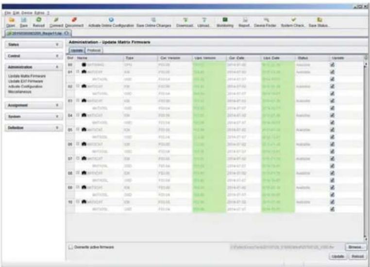
text_image
Edit Edit Device Agree 2 Open Save Refresh Connect Document Activate Online Configuration Save Online Changes Download... Upload... Monitoring Repeat... Data Filter System Check... Save Status... UPR10000000000_Respective Administration - Update Matrix Firmware Parameters Pre Slovenia Sort Name Type Cat Version Use Version Car Date List Date Status Update 80 https://www.10000000000/ 81 https://www.10000000000/ 82 https://www.10000000000/ 83 https://www.10000000000/ 84 https://www.10000000000/ 85 https://www.10000000000/ 86 https://www.10000000000/ 87 https://www.10000000000/ 88 https://www.10000000000/ 89 https://www.10000000000/ 90 https://www.10000000000/ 91 https://www.10000000000/ 92 https://www.10000000000/ 93 https://www.10000000000/ 94 https://www.10000000000/ 95 https://www.10000000000/ 96 https://www.10000000000/ 97 https://www.1000000000 98 https://www.10000-1-1-1/2/2/2/2/2/2/2/2/2/2/2/2/2/2/2/2/2/2/2/2/2/2/2/2/2/2/2/2/2/2/2/2/2/2/2/2/2/2/2/2/2/2/2/2/2/2/2/2/2/2/4 99 https://www.1.1.1.1.1.1.1.1.1.1.1.1.1.1.1.1.1.1.1.1.1.1.1.1.1.1.1.1.1.1.1.1.1.1.1.1.1.1.1.1.1.1.1.1.1.1.1.1.1.1.4 Software active network Update Next: www.mim.com, www.mim.com, www.mim.com, www.mim.com, www.mim.com, www.mim.com, www.mim.com, www.mim.com, www.mim.com, www.mim.com, www.mim.com, www.mim.com, www.mim.com, www.mim.com, www.mim.com, www.mim.com, www.mim.com, www.mim.com, www.mim.com, www.mim.com, www.mim.comFIGURE 4-66. ADMINISTRATION—UPDATE MATRIX FIRMWARE
- Start the update by pressing the Update button in the appearing pop up window.
- Restart the Matrix after the update by pressing the Restart matrix button in the lower part of the working area.
For a safe initialization of the matrix, we recommend a cold start (power cycle).
CHAPTER 4: CONFIGURATION
NEED HELP? LE AVE THE TECH TO US
LIVE 24/7 TECHNICAL SUPPORT
1.8 7 7.87 7.2269
4.16.2 EXTENDER UPDATE
The firmware of the extenders connected to the matrix can be updated in this menu.
You have the following option to access the menu:

PREPARATION
Take the following steps in order to be prepared for the extender update:
-
Save the matrix configuration externally (see Section 2.9). Open Extras > Options in the menu bar and insert the name of the directory from which the update files should be sourced in Firmware Directory.
-
Connect all hot spare extenders to the matrix.
CAUTION: For network stability, an update via WLAN is not recommended.
PERFORMING THE UPDATE IN STANDARD MODE (PARALLEL UPDATE)
- Select Administration > Update EXT Firmware in the task area. The standard mode for the parallel update will be selected by default and the Upload Firmware tab will be opened.

text_image
Edit - Edit Device Format Gross: Gare Reload: Reload Comment: Document Activate Online Configuration Raw Online Changes Download: Upload Monitoring Report Device Finder System Check Save Status 20180000000000000000000000000000000000000000000000000000000000000000000000000000000000000000000000000000 2018000000000000000 Administration - Update EXT Firmware Parallel Mode (recommended) Parallel update of inverters, executed separately on each ID bound Sequential Mode Sequential update mode in order to update specific inverters Step 3 Update Firmware Step 3 Update Firmware Hardware File EXT-PCPU 2.57 F12.41 2018-12-29 2 E12C1CM 2.57 F13.65 2019-12-14 2 E13C2CPV 2.69 F14.33 2019-12-23 2 E13C3CM 2.69 F15.96 2019-12-27 2 E13C4PV 2.69 F16.54 2019-12-34 2 E13C5CM 2.67 F16.58 2019-12-35 2 E13C6CM 2.67 F16.58 2019-12-35 2 Upload Progress 8% Upload Messages Save ProtocolFIGURE 4-67. ADMINISTRATION—UPDATE EXT FIRMWARE
CHAPTER 4: CONFIGURATION
- Before the actual update process, all firmware files have to be uploaded to the respective I/O boards on that extenders will have to be updated. If a newer firmware is available, appropriate I/O boards will be automatically selected for the upload in the Selected column and highlighted in green.
- Start the upload and distribution of the update files by pressing the Upload button.
NOTE: By performing the upload process, no update files will be installed. The update process can be performed at a later time.
If all I/O cards are not selected, the upload of the update files will be performed in sequence.
- After finishing the upload process, successful completion will be confirmed by a popup message. If you want to directly start the actual update process, you will have to confirm this by pressing the Yes button. You will be immediately forwarded to the Update Firmware tab.
NOTE: When updating an identical or an older firmware version than the version currently installed, the Force Update option in the lower part of the working area must be enabled.
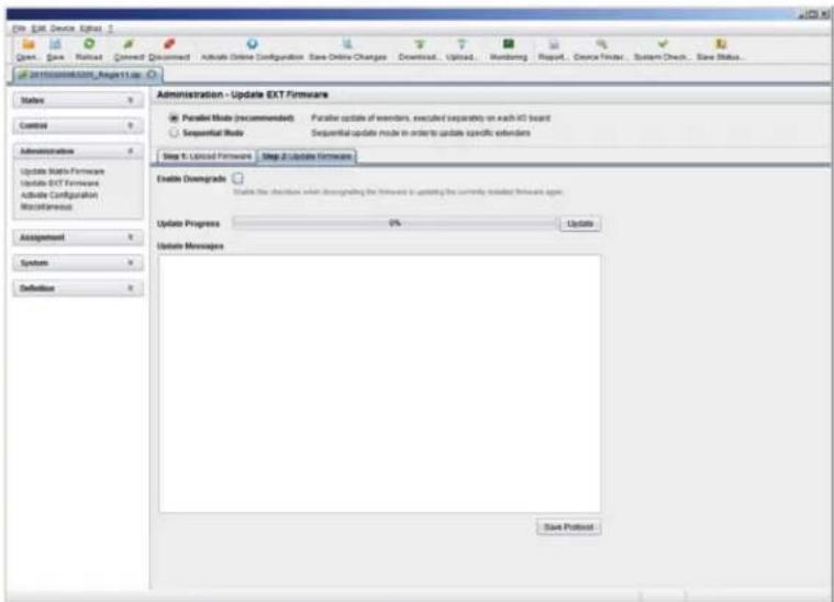
text_image
Edit Edit Device Options Open... Save... Print... Connect Document Active Online Configuration Save Online Changes Download... Upload... Monitoring Request... Device Finder... System Check... Save Status... Edit Edit Device Options Help... Name Control Administration Update Matrix Firmware Update EXT Firmware Activate Configuration Miscellaneous Assignment System Definition Administration - Update EXT Firmware Parallel Mode (recommended) Further update of reminders executed separately on each iOS board Sequential Mode Sequential update mode in order to update specific reminders Step 1: Upload Firmware Step 2: Update firmware Enable Downgrade Enable the checkbox when delivering the firmware to updating the currently installed firmware ages. Update Progress 0% Update Update Messages Save ProtocolFIGURE 4-68. ADMINISTRATION—UPDATE EXT FIRMWARE
- Start the actual update process by pressing the Update button.
NOTE: Just before the update process, all affected I/O boards will be set into Service Mode and retrieved gradually after finishing the respective updates.
PERFORMING THE UPDATE IN EXPERT MODE (SEQUENTIAL UPDATE)
Take the following steps in order to be prepared for the extender update:
- Select Administration > Update EXT Firmware and select Expert Mode in the upper part of the working area. All extenders that can be updated will be automatically selected and highlighted in green.
CHAPTER 4: CONFIGURATION
NEED HELP? LE AVE THE TECH TO US
LIVE 24/7 TECHNICAL SUPPORT
1.8 7 7.87 7.2269
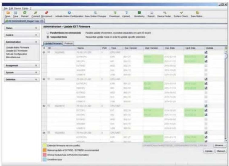
text_image
Edit Exit Device Options 2 Open, Save, Retired, Connect, Document, Activate Online Configuration, Save Online Changes, Download, Upload, Monitoring, Report, Device Finder, System Check, Save Status 2010-03-01/2010-03-01/2010 Administration - Update EXIT Firmware Parallel Note (recommended) Parallel update of members, executed separately on each ID board Sequential Note Sequential update mode in order to update specific elements Update Hardware 输出 ID Name Part Type Cut Version Up/ Version Cut Date Up/ Date Update 01 10000000 75-142 (19:28) 1 CPU UNIT 0.076CPG 0.06 001.27 2014-02-19 2014-03-13 0.076CPG WD 0.02 001.27 2014-03-13 0.75WBD WD 0.02 001.24 2014-04-07 0.062DP 0.02 001.15 2014-05-25 0.062DP WD WD WD WD WD WD WD WD WD WD WD WD WD WD WD WD WD WD WD WD WD WD WD WD WD WD WD WD WD WD WD WD WD WD WD WD WD WD WD WD WD WD WD WD WD WD WD WD WD WD WD WD WD WD WD WD WD WD WD WD WD WD WD WD WD WD WD WD WD WD WD WD WD WD WD WD WD WD WD WD WD WD WD WD WD WD WD WD WD WD WD WD WD WD WD WD WD WD WD WD W 02 10000000 75-142 (19:28) 1 CPU UNIT 0.75CPG 0.06 001.27 2014-03-19 2014-04-13 0.75CPG WD 0.02 001.27 2014-05-25 0.75WBD WD 0.02 001.24 2014-06-07 0.62DP 0.02 001.15 2014-07-29 0.62DP WD WD WD WD WD WD WD WD WD WD WD WD WD WD WD WD WD WD WD WD WD WD WD WT 0.62CPG 0.06 001.24 2014-08-29 0.62CPG WD WD WD WD WD WD WD WD WD WD WD WD WD WT 0.62CPG 0.06 001.24 2014-09-29 0.62CPG 0.06 001.24 2014-10-29 0.62CPG 0.06 001.24 2014-11-29 0.62CPG 75-142 (19:28) 1 CPU UNIT 0.75CPG 75-142 (19:28) 1 CPU UNIT 0.75CPG WD 75-142 (19:28) 1 CPU UNIT 0.75CPG WD 75-142 (19:28) 1 CPU UNIT A3 15 3533673 75-142 (19:28) 1 CPU UNIT A3 3533673 75-142 (19:28) 1 CPU UNIT A3 3533673 75-142 (19:28) 1 CPU UNIT A3 3533673 75-142 (19:28) 1 CPU UNIT A3 3533673 75-4533673 75-4533673 A3 3533673 75-4533673 A3 3533673 75-4533673 A3 3533673 75-4533673 A3 3533673 75-4533673 A3 3533673 75-4633673 A3 3533673 75-4633673 A3 3533673 75-4633673 A3 3533673 75-4633673 Calendar software version conflict Varical update of EXITWD / EXITMSD recommended Timing module type (CPU/CPU/MOSM) Unidentified typesFIGURE 4-69. ADMINISTRATION—UPDATE EXT FIRMWARE
- Set the matrix into Service Mode upon request in the popup window or via Matrix > Activate Service Mode in the menu bar. During activation, all matrix functions are disabled on the I/O boards on which an update is currently performed. An OSD picture indicates the activation of the Service Mode and is displayed on all monitors that are connected to the matrix via a CON device. In addition, the Service Mode is indicated by a red tool icon in the lower part of the working area.
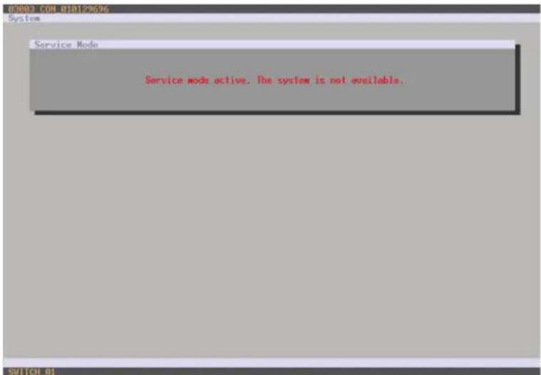
text_image
IC0002 CON 010129696 System Service Mode Service mode active. The system is not available.FIGURE 4-70. OSD VIEW—SERVICE MODE
- Start the update by pressing the Update button in the lower part of the working area.
CHAPTER 4: CONFIGURATION
- Quit Service Mode after updating after responding to the confirmation request in the popup window or via Matrix > Deactivate Service Mode in the task area.
- Verify after the update in the Java tool via Administration > Update EXT Firmware in the Protocol tab of the Expert Mode that the updates for all extenders have been installed correctly.
4.17 LICENSE MANAGEMENT
In this menu, the matrix can be upgraded with new function bundles by installation of license keys.
To obtain license keys to upgrade matrix functions, contact Black Box Technical Support at 877-877-2269 or info@blackbox.com. You have the following option to access the menu.

JAVA TOOL
To activate a function bundle, proceed as follows:
- Select Administration > Miscellaneous > License Management in the task area.
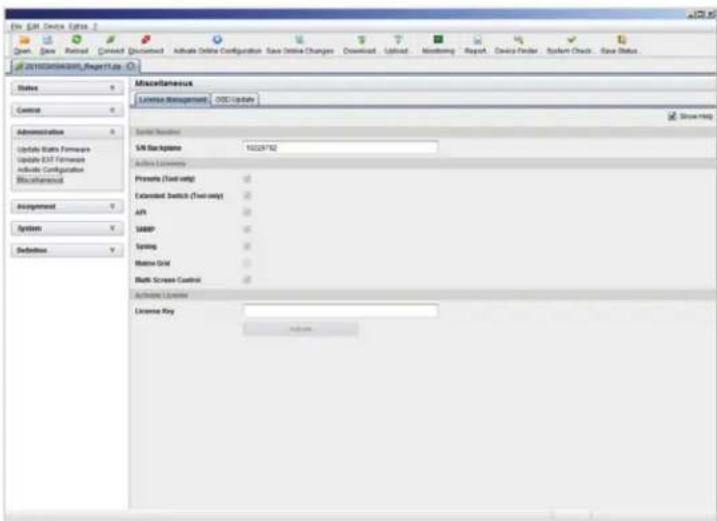
text_image
File: SIR Device Options Open Save Reset Cancel Document Active Online Configuration Save Online Changes Download Upload Monitoring Report Device Finder System Check Save Status all SIR Device Options Help Use Status Control Administration Update Data Features Update EXT Features Include Configuration Miscellaneous Assignment System Definitions Miscellaneous License Management OBC Update Start Menu SIR Background 10228762 Active Listeners Promote (Tool only) Extended Switch (Tool only) API SABP Spring Matrix Grid Both Screen Control Active License License Key Add toFIGURE 4-71. ADMINISTRATION—MISCELLANEOUS—LICENSE MANAGEMENT
- Enter your license key in the working area under Activate Bundles in the License Key field.
- To activate the license key, press the Activate button. The new functions will be immediately enabled; a restart of the matrix will not be necessary.
The Compact KVM Matrix Switches can be operated in three different ways.
1. Direct Switching
- via a keyboard connected to a CON port and the favorites
- by a macro keyboard connected to a console port
2. OSD
- via keyboard/mouse directly connected to the CPU board of the matrix
- via keyboard/mouse connected to a CON Unit and the OSD
3. External Switching Commands
- via an external computer via Java tool (network connection required)
- via a media control (network or serial connection required)
5.1 OPERATION VIA HOTKEYS
5.1.1 DIRECT SWITCHING
Direct switching by favorites on a keyboard is the fastest way for a user to switch at his console between different CPUs. This offers the option to switch video, keyboard and mouse or video only.
DIRECT SWITCHING OF VIDEO, KEYBOARD AND MOUSE
- Start Command Mode with the hotkey. Shift and Scroll LEDs on the keyboard will flash if Command Mode is activated.
- Enter the index number of the new CPU from the list of favorites and confirm with
.
At the same time, the Command Mode is closed and the console is connected to the new CPU, which takes over complete control.
Example: Switching to favorite CPU 7 with video, keyboard and mouse
NOTE: Fastest switching time can be achieved by using identical mice, keyboards and monitors. This contributes to a smooth and seamless direct switching of the matrix.
SWITCHING IN PRIVATE MODE
- Start Command Mode with the hotkey. Shift and Scroll LEDs on the keyboard will flash if command mode is activated.
- Enter the index number of the new CPU from the list of favorites and confirm with
, pressed at the same time.
At the same time, the Command Mode is closed and the console is connected to the new CPU with complete control in Private Mode.
Example: Switching to favorite CPU 3 in Private Mode
DIRECT SWITCHING OF VIDEO
- Start Command Mode with the hotkey.
Shift and Scroll LEDs on the keyboard will flash if command mode is activated. - Enter the index number of the new CPU from the list of favorites and confirm with
.
At the same time, Command Mode is closed and the console is connected to the new CPU with video only.
Example: Switching to favorite CPU 1 with video only
SWITCH TO PREVIOUS CPU
- Start Command Mode with the hotkey. Shift and Scroll LEDs on the keyboard will flash if Command Mode is activated.
- Press the key
of your keyboard.
At the same time, Command Mode is closed and the console is connected to the previous CPU with complete control.
NOTE: If you switch to a CPU that was previously connected with Video Access only, you will be connected to this CPU with full KVM access.
NOTE: You can only switch to valid, unused CPUs using hotkeys. The options Force Connect and Force Disconnect as well as the restrictions of the User ACL and CON ACL are taken into account.
Hotkeys are only supported if neither Enable User Login nor the Enable User ACL is selected and the user is logged in the OSD.
DISCONNECT CURRENT CONNECTION
- Start Command Mode with the hotkey. Shift and Scroll LEDs on the keyboard will flash if Command Mode is activated.
- Press the
key on your keyboard.
The Command Mode is closed and the console is disconnected from the previous connected CPU.
5.1.2 SCAN MODE
Scan Mode enables fast switching between video signals from different CPUs registered as favorites without continuously using the hotkey.
Switching between two video signals can even take place within one frame.
- Start command mode with the hotkey. Shift and Scroll LEDs on the keyboard will flash if command mode is activated.
- Press the key
and hold it down. You can now enter the index numbers of the various CPUs from the list of favorites with the keyboard and immediately switch to the video signal of the respective CPU after entering the index number. - Leave Scan Mode by pressing
+ .
NOTE: Optimal results can be achieved by the use of as identical resolutions as possible. This contributes to a smooth and seamless function of the scan mode.
5.1.3 FUNCTION KEYS -
In Command Mode, you can retrieve the macros 1–16 with the function keys
The stored command sequence for the appropriate function key is executed and Command Mode is left immediately.
NOTE: It is not necessary to use
5.1.4 ADDRESSING OF MAIN AND SUB MATRICES
The Compact KVM Matrix Switch can be cascaded over two levels. You can send the commands (including opening the OSD) to either the main or the sub matrix.
When in command mode, you can select whether commands should be handled in the main or the sub matrix.
OSD Access
- OSD access to the main matrix:
, , (optional),
♦ OSD access to the sub matrix:, , ,
To do a cross-matrix switching, proceed as follows:
- Open the OSD of the master matrix with the following keyboard sequence:
, - Select the CPU device configured as Tie Line in the CPU selection list and press
to switch. - Open the OSD of the sub matrix with the following keyboard command:
, , - Select your target CPU in the CPU selection list of the sub matrix.
NOTE: The selected master matrix / sub matrix mode is permanently activated until the other mode will be manually activated. This means that if you select , all prospective commands will be sent to the sub matrix, but not if the Command Mode is left in the meantime.
You have the following option to perform switching operations with the Compact KVM Matrix Switch.

OSD
- Select Switch in the main menu.
Press

text_image
CON/CPU Data CON device 03002 CON_010167832 CPU device 01004 CPU_040011492 CON assigned CPU assigned CPU connected 01004 CPU_040011492 CON connected 03002 CON_010167832 Status EXI list EXI listFIGURE 5-1. SWITCH MENU
To switch the console to any available CPU, proceed as follows:
- Select in the CPU Devices list on the left hand side that one that should be connected to the CON Device.
- Confirm desired connection type with the appropriate keyboard command.
Switching operations from the own CON Device can only be performed on CPU Devices that are available in the CPU Devices list.
NOTE: Listed CPU Devices highlighted in red color are currently connected in Private Mode and are blocked by the connected CON Device.
The matrix offers the ability to execute KVM switching operations via a selection list for CPU Devices next to the OSD in full screen.
To use the selection list for CPU Devices, proceed as follows:
-
Activate the Enable CPU Selection List option in the Configuration menu for those consoles where the selection list for CPU Devices should be available.
-
Execute the key sequence for opening the OSD. The selection list immediately appears in the preset position of the extender OSD.
NOTE: Pressing
- Execute the desired switching operation by pressing the respective key (see Section 5.3). To prevent a switching operation and access OSD, press
. To close the selection list, press .

text_image
CON_01014888/ Switch 01001_CPU_010135823 01000_CPU_010144317 01002_CPU_010148543 01004_CPU_010182323 01003_CPU_010182324FIGURE 5-2. SELECTION LIST CPU DEVICES
ACTIVATING THE AUTOMATIC SCAN MODE FOR CPU DEVICES
The matrix offers the ability to use a scan mode based on the favorite list of each console or user. Scan mode allows the matrix to switch in sequence between the CPU Devices in the favorite list within a predefined time. All scans are performed in video only mode.
To configure scan mode, refer to Section 4.11.1.
You have the following option to activate the scan mode:

To activate scan mode, proceed as follows:
- Define a favorite list for the respective CON Device or user (see Section 4.11.4 for CON Devices or see Section 4.5.2 for users).
- Start Command Mode with the hotkey and press
to open OSD. - Select one of the CPU Devices in the CPU selection list that are defined in your favorite list.
- Confirm your selection by pressing the CPU Scanner button. The scan will automatically start.
- If you have enabled the Force CPU Scan option, the scan will automatically start after switching the respective CON Device to any CPU Device from the favorite list without the need to press the CPU Scanner button.
5.3 EXTENDED SWITCHING
You have the following option to perform switching operations with the Compact KVM Matrix Switch.

text_image
OSD JAVAOSD
To switch any console to any available CPU, proceed as follows:
- Select Extended Switch in the main menu.
NOTE: Pressing

text_image
03001 CON_010125430 -- admin Extended Switch F1:10 F2:Name F3:Next F4:Previous FS:Refresh F6:Find ESC CON Devices 03007 CON_010123467 03005 CON_010123672 03004 CON_010124381 03002 CON_010125062 03008 CON_010125321 03001 CON_010125430 03003 CON_010129653 03006 CON_010129696 CON/CPU Data CON device CPU device 03007 CON_010123467 CON assigned CPU assigned CPU connected CON connected Status Status EXG list EXT listFIGURE 5-3. EXTENDED SWITCH MENU
- Select in the CON Devices list on the left hand side the one that should be switched to a CPU Device and open it by pressing
. - Select in the CPU Devices list on the left hand side that one that should be connected to the open CON Device.
- Confirm the desired connection type with the respective keyboard command.
Switching operations from the user's CON Device can only be performed on CPU Devices that are available in the CPU Devices list.
The following information is shown in this menu.
TABLE 5-1. EXTENDED SWITCH MENU OPTIONS
| FIELD DESCRIPTION | |
| CON device Assigned physical extender unit (CON Unit) | |
| CON assigned Virtual CON Device that is assigned to the real CON Device | |
| CPU connected Currently connected CPU Device | |
| CON status Current connection status (CON Device) | |
| EXT list List of all available physical extender units (CON Units) | |
| CPU device Assigned physical extender unit (CPU Unit) | |
| CPU assigned | Real CPU Device that is assigned to a virtual CPU Device |
| CON connected | Currently connected CON Device |
| CPU status | Current connection status (CPU Device) |
| EXT list List of all available physical extender units (CPU Units) | |
You can select the following switching functions.
TABLE 5-2. SWITCHING FUNCTIONS
| FUNCTION | KEYBOARD COMMAND |
| Set a video only connection | |
| Set a KVM connection | |
| Set a KVM connection in private mode (video sharing disabled). | + |
| Disconnect a CON Device from a CPU Device. |
You have two options to perform switching operations for the Compact KVM Matrix Switch via Java tool.
Possibility 1:
- Select Switch in the main menu.
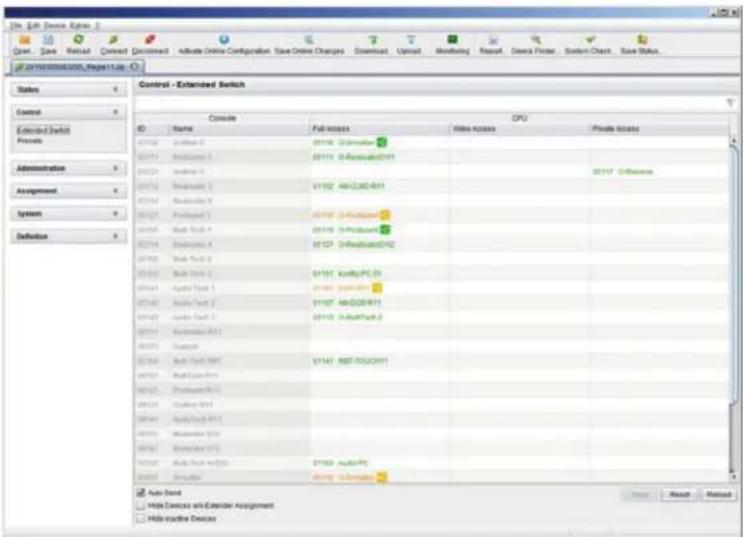
text_image
Control - Extended Switch Console CPU Name Full access Video access Private access 01712 2ndhand 2 01713 2ndhand 3 01714 2ndhand 4 01715 2ndhand 5 01716 2ndhand 6 01717 2ndhand 7 01718 2ndhand 8 01719 2ndhand 9 01720 2ndhand 10 01721 2ndhand 11 01722 2ndhand 12 01723 2ndhand 13 01724 2ndhand 14 01725 2ndhand 15 01726 2ndhand 16 01727 2ndhand 17 01728 2ndhand 18 01729 2ndhand 19 01730 2ndhand 20 01731 2ndhand 21 01732 2ndhand 22 01733 2ndhand 23 01734 2ndhand 24 01735 2ndhand 25 01736 2ndhand 26 01737 2ndhand 27 01738 2ndhand 28 01739 2ndhand 29 01740 2ndhand 30 01741 2ndhand 31 01742 2ndhand 32 01743 2ndhand 33 01744 2ndhand 34 01745 2ndhand 35 01746 2ndhand 36 01747 2ndhand 37 01748 2ndhand 38 01749 2ndhand 39 01750 2ndhand 40 01751 2ndhand 41 01752 2ndhand 42 01753 2ndhand 43 01754 2ndhand 44 01755 2ndhand 45 01756 2ndhand 46 01757 2ndhand 47 01758 2ndhand 48 01759 2ndhand 49 01760 2ndhand 50 01761 2ndhand 51 01762 2ndhand 52 01763 2ndhand 53 01764 2ndhand 54 01765 2ndhand 55 01766 2ndhand 56 01767 2ndhand 57 01768 2ndhand 58 01769 2ndhand 59 01770 2ndhand 60 01771 2ndhand 61 01772 2ndhand 62 01773 2ndhand 63 01774 2ndhand 64 01775 2ndhand 65 01776 2ndhand 66 01777 2ndhand 67 01778 2ndhand 68 01779 2ndhand 69 01780 2ndhand 70 01781 2ndhand 71 01782 2ndhand 72 01783 2ndhand 73 01784 2ndhand 74 01785 2ndhand 75 01786 2ndhand 76 01787 2ndhand 77 01788 2ndhand 78 01789 2ndhand 79 01790 2ndhand 80 Auto Send Hide Devices with Calendar Assignment Hide Active DeviceFIGURE 5-4. CONTROL—EXTENDED SWITCH
All connected consoles and the associated CPU connections are shown in columns in the working area in this menu.
NOTE: Switching operations can only be performed in online mode. That means an active network connection is required between the matrix and the Java Tool.
To set a KVM connection between a console and a CPU, double-click on the corresponding selection box within the Full Access column and select the requested CPU.
To set a video connection between a console and a CPU, double-click on the corresponding selection box within the Video Only column and select the requested CPU.
To set a Private Mode connection between a console and a CPU, double-click on the corresponding selection box within the Private Mode column and select the requested CPU.
NOTE: If a CPU console does not have access rights, it will not appear in the list.
The following symbols are shown in the connection overview.
TABLE 5-3. SYMBOLS
| SYMBOL DESCRIPTION | |
 | CON Device is connected via Shared Access with at least one further console to the same CPU. The CON Device has Full Access at the moment. |
 | CON Device is connected via Shared Access with at least one further console to the same CPU. The CON Device has a Video Access connection at the moment. |
You can use the following buttons to perform a switching operation.
TABLE 5-4. SWITCHING BUTTONS
| BUTTON FUNCTION |
| Send Send switching operations to the matrix |
| Reset Disconnect all existing connections within the matrix |
| Reload Reload switching status |
NOTE: When the Auto Send function in the left lower corner of the work area is ticked, switching operations will be completed immediately without user confirmation via the Send button.
When the Hide Devices w/o Extender Assignment function in the left lower corner of the work area is ticked, only CON and CPU Devices that are assigned to extenders are shown.
- Select Status > Matrix View in the task area or select Status > Grid Port View when using a Matrix Grid.

text_image
File Edit Device Options Open Save Retired Connect Document Active Online Configuration Save Online Changes Download Upload Membering Report Device Finder Scroll Check Save Status all in recontext, Report Use Status - Matrix View Radio View Grid Port New Radio Features EXT Networks Control Administration Assignment System Definition Actions Automatic Reset Show Port Numbers Switch Show Mode Show Multi-System Control Show Substandard Line 1.0 (1.2) To Port Color Ending Full Access Video Access Grid Line Sound Port No Access Fixed Port To Port Sequence Multi-System Function Reconfiguration Switch OFF Sprecher @ CRT Sprecher to Working PC 62FIGURE 5-5. STATUS—MATRIX VIEW
To perform switching operations between CON and CPU Devices, proceed as follows:
- Move the mouse cursor to the port that has to be switched.
- Hold down the left mouse button and move the cursor to the port that has to be connected to the initial port. The current cursor movement will be displayed by a black auxiliary line.
- Release the left mouse button. A popup to select the available switching type (Full Access, Video Access or Private Mode) will be opened.
- Select the desired switching type. The switching operation will be immediately executed. At the same time all extender units that are assigned to the involved devices will be switched.
NOTE: If a port is shown with a red cross on Matrix View, the console does not have access rights to the CPU connected to that port.
To disconnect an existing connection between CON and CPU Devices, proceed as follows:
- Click on the port that is to be disconnected by using the right mouse button.
- Select the Disconnect function in the popup that appears. The connected ports will be immediately disconnected. At the same time, all further connections of the extenders assigned to the involved devices will be disconnected.
You can independently switch single extenders within configurations consisting of CON and CPU devices with multiple extenders. You have the following option to switch single extenders.

OSD
To switch a single extender a device with multiple extender, proceed as follows:
- Select Switch in the main menu.

text_image
CON 010157832 Switch CPU Devices 01003 CPU 010207794 01001 CPU_016090105 01004 CPU_040011492 CON/CPU Data CON device 03002 CON_010167832 CON assigned CPU connected 01004 CPU_040011492 Status EXI list 010167832 0301 EXI 010167832 010205247 034 EXI_010203247 CPU device 01003 CPU_010207794 CPU assigned CON connected Status EXI list 010135668 011 EXI 010135668 010207794 011 EXI 010207794 Video only access with video set & screen disabled COM access in standard mode with video sharing enabled COM access in private mode with video sharing enabled EXI access in your CPU device COM access in the CPU compare to non-user featuresFIGURE 5-6. SWITCH MENU
- Select the respective CPU Device in the CPU selection list containing the extender you want to have access to.
- Press the function key
on the keyboard. The standard will change into the switching mode for single extenders. - Select the extender you want to switch within your CON Device.
- Access the extender list of the selected CPU Device by pressng the key
. - Select the CPU extender you want to switch to and press the key
to execute the switching operation.
NOTE: Switching of single extenders from a Device is only possible in video only mode. Single exenders of a Device that are already switched will be highlighted with "!".
KVM extender CON Units connected to a local source (computer, CPU) can be locally switched via the matrix. Switching is performed between the local source and the KVM connection and can be executed via hotkeys or via OSD.
If you switch to the local source, the KVM connection will be automatically disconnected.
NOTE: When using CON Units with the possibility to connect a local source (computer, CPU) in a Multi-Screen Control environment, the local switching will be disabled.
You have the following option to switch to the local source.

OSD
- Select Switch in the main menu.

text_image
CON 01018245 Switch F1:ID F2:Name E3:Next E4:Previous FS:Refresh F5:Find ESC CPU Devices Local CPU 01002 CPU_01 01003 CPU_02 01006 CPU_03 01007 CPU_04 01008 CPU_05 01001 CPU_06 01006 CPU_07 01004 CPU_08 CON/CPU Data CON device CPU device 08004 CON_01018245 01005 CPU_07 CON assigned CPU assigned CPU connected CON connected Status Status EXT list EXT listFIGURE 5-7. CON SWITCH
To switch to a local source, proceed as follows:
- If you are not in the Switch menu of the OSD, start Command Mode with the hotkey (see Section 4.1).
- Press
to open OSD. You will see a list of all available CPUs as a start menu. - Switch to the CPU in the Local CPU list. The switching operation to the local source will be performed immediately.
NOTE: The local source (computer, CPU) will be only shown in the OSD if the connected CON Unit includes the option for a local connection.
As an alternative, the following keyboard commands are available to switch to the local source.
TABLE 5-5. KEYBOARD COMMANDS TO SWITCH TO A LOCAL SOURCE
| FUNCTION KEYBOARD COMMAND |
| Switching to extender connection,,<1>,, |
| Switching to extender connection 2 (only with redundant CON Units),<k>,<2>,, |
| Switching to the local source (computer, CPU),<|>,, |
5.6 MULTI-SCREEN CONTROL
The Multi-Screen function contains a switching of the USB-HID signal between different statically connected sources (computer, CPU) within a CON Device and can be performed in two different ways:
SWITCHING VIA MOUSE
The switching of the USB-HID signal can be made by a movement of the mouse pointer beyond the edge of the current display to a neighboring display (see Section 4.11.7).
To perform a switching operation by movement of the mouse pointer, proceed as follows:
- Move the mouse pointer to the edge of the display that borders the neighboring display vertically or horizontally.
- Move the mouse pointer beyond the edge of the display. The mouse pointer will appear on the adjacent display. The switching operation has been performed and the USB-HID signal will now be available at the target display.
SWITCHING VIA KEYBOARD
Switching of the USB-HID signal can also be achieved using the keyboard (for configuration, see Section 4.11.7).
To perform a switching operation via keyboard command, proceed as follows:
- Start Command Mode with the hotkey (see Section 4.1).
- Select the target display by pressing the respective key on the numeric pad of the keyboard. The switching operation will be performed and the USB-HID signal will be available at the target display.
You can select the following switching operations.
TABLE 5-6. SWITCHING OPERATIONS
| KEYBOARD COMMAND FUNCTION |
| Switching of the USB-HID signal to the display (CON Unit with keyboard and mouse) |
| Switching of the USB-HID signals to display #1 |
| Switching of the USB-HID signals to display #2 |
| Switching of the USB-HID signals to display #3 |
| Switching of the USB-HID signals to display #4 |
5.7 USB 2.0 SWITCHING
Switching USB 2.0 extenders basically works like switching KVM extenders. The following scenarios to switch USB 2.0 extenders are possible.
- An extender unit with USB 2.0 will be created and assigned to an already existing device with existing KVM extender units (see Section 4.10 or Section 4.11.1).
- A separate device for the extender unit with USB 2.0 will be created without assigning a KVM extender unit to that device.
This possibility offers separate switching of the USB 2.0 signal (see Section 4.10 or Section 4.11.1).
NOTE: Switching USB 2.0 signals uses Extended Switching functionality (see Section 5.3).
When using parallel operation within the matrix, set the Release Time in the Configuration > Switch menu to 10 seconds or more (see Section 4.11.6). Otherwise, the connection of the USB 2.0 extender will not be established for security and stability reasons.
5.8 PRESETS
Predefined macros to switch the matrix without loading a new configuration can be created and activated in this menu.
You have the following option to access the menu.

- Select Control > Presets in the task area.
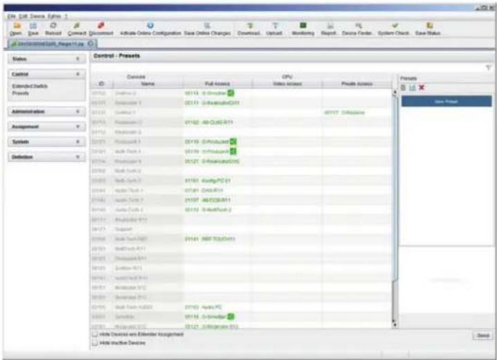
text_image
Control - Presents Control Extended Blocks Projects Administration Assignment Symbols Definitions Controls Control Name Full Access OPC Video Access Private Access New Page Hillu Digital vsn Ebbender Angrisheet Hillu Digital DisplayFIGURE 5-8. CONTROL-PRESETS
To create a new switch macro, proceed as follows:
- Open a new switch macro by clicking the New symbol in the right column of the working area.
You are asked if the existing connections should be taken over for the new switch macro. - Set the desired switching operations in the corresponding columns (Full Access, Video Only or Private Mode) by using a double click on the appropriate selection box or use the function for a disconnect (Disconnect CPU).
- Save the created switch macro by clicking the Save symbol in the right column of the working area. A save dialog will be opened.
- Enter a name or the new switch macro and confirm by pressing the Ok button in the save dialog.
- By clicking on a selected switch macro with the right mouse button, you can create a copy of the current switch macro when using the Save as... option.
- Previously saved macros can be deleted by pressing the Delete symbol.
To load a predefined switching, proceed as follows:
- Select the switch macro in the right column of the working area that has to be loaded.
- Activate the selected switch macro by pressing the Send button on the bottom right of the working area.
NOTE: A predefined switch macro can only be activated in online mode. When loading presets, only those switching operations that are compliant with the hardware and the configuration of the currently used matrix are taken into account.
5.9 SERIAL INTERFACE
Predefined macros to switch the matrix without loading a new configuration can be created and activated in this menu.
You have the following option to access the menu.

The Compact KVM Matrix Switch offers the option to switch via a serial interface (RS-232).
Detailed information for the serial interface and the corresponding switching commands are available in form of an API (application programming interface) at blackbox.com or ftp://ftp.blackbox.com/manuals/A/acx048_API_rev2.pdf.
5.10 POWER ON AND POWER DOWN FUNCTIONS
5.10.1 RESTART
You have the following options to perform a restart.


OSD
- Select Configuration > Restart Matrix or Restart IO Board in the main menu to restart either the matrix or the I/O boards.
- Confirm the selection with Okay button.
The matrix and the I/O boards will be restarted with the current settings.
JAVA TOOL
- Select Matrix > Restart Matrix in the menu bar.
The matrix will be restarted with the current settings.
NOTE: The boot process of the matrix might take longer if there is no physical network connection available.
You have the following option to perform a restart.

CAUTION: If you perform a (factory) reset, all current settings and all configurations stored in the matrix will be lost. This also applies to the network parameters (reset to DHCP) and the admin password.
NOTE: If a firmware update has been installed since the delivery, the matrix will be set to the state defined there.
OSD
- Select Configuration > Factory Reset in the main menu.
- Confirm the selection with the Okay button.
The matrix will be reset to factory settings.
5.10.3 POWER DOWN
You have the following option to shut down the system or single components.

OSD
To shut down the system, proceed as follows:
- Select Configuration > Shut down Matrix in the main menu.
- Confirm the selection with the Okay button.
The matrix will be shut down.
To shut down an I/O board, proceed as follows:
- Select Configuration > Shut Down IO Board in the main menu.
- Confirm the selection with the Okay button.
The I/O board will be shut down.
5.11 SUMMARY OF KEYBOARD COMMANDS
The following table contains a summary of keyboard commands that can activate extender and matrix functions after executing the hotkey.
TABLE 5-7. EXTENDER KEYBOARD COMMANDS
| KEYBOARD COMMAND DESCRIPTION | |
| Download of DDC information for the monitor connected to the CON Unit into the CPU Unit | |
| Switch to the KVM connection 1 (only with HDMI CON Units with available connection for a local source) | |
| Switch to the KVM connection 2 (only with HDMI CON Units with available connection for a local source and a redundant interconnection) | |
| Switch to local source (computer, CPU) (only with HDMI CON Units with available connection for a local source) | |
| USB-HID Ghosting: Write device descriptions of the input devices connected to the CON Unit into the CPU Unit. Activate the emulation in the CPU Unit. | |
| Activate the emulation of already stored device descriptions in the CPU Unit | |
| Deactivate the emulation of active device descriptions in the CPU Unit. The input devices connected to the CON Unit will be passed transparently to the source (computer, CPU) | |
| Deactivate the emulation of active device descriptions in the CPU Unit. Delete the descriptions out of the CPU Unit. The input devices connected to the CON Unit will be passed transparently to the source (computer, CPU) | |
| Switch to video channel 1 of the Dual-Head CPU Unit (dual-head series only) | |
| Switch to video channel 2 of the Dual-Head CPU Unit (dual-head series only) | |
TABLE 5-8. MATRIX KEYBOARD COMMANDS
| KEYBOARD COMMAND DESCRIPTION | |
| Open OSD | |
| Open OSD of the master matrix in a cascaded environment | |
| Open OSD of the sub matrix in a cascaded environment | |
| Set a KVM connection (keyboard, mouse and video) to the selected source (computer, CPU) | |
| Set a video only connection to the selected source (computer, CPU) | |
| Set a Private Mode connection to the selected source (computer, CPU) | |
| Close the current connection of the console | |
| Switch back to the previous connected source (computer, CPU) with a KVM connection | |
| Switch to a source (computer, CPU) stored in the Favorite List with a KVM connection (video only or Private-Mode connection) | |
| Execute a predefined macro | |
| Change the hotkey according to the predefined hotkey table | |
| Define freely selectable hotkey | |
| Change the hotkey for direct OSD access according to the predefined hotkey table | |
| Define freely selectable hotkey for direct OSD access | |
| Switch the USB-HID signal to the user's display (CON Unit with keyboard and mouse) | |
| Switching of the USB-HID signals to display #1 | |
| Switching of the USB-HID signals to display #2 | |
| KEYBOARD COMMAND DESCRIPTION |
| ,Switching of the USB-HID signals to display #3 |
| ,Switching of the USB-HID signals to display #4 |
CHAPTER 6: MAINTENANCE
NEED HELP?
LE AVE THE TECH TO US
LIVE 24/7
TECHNICAL
SUPPORT
1.87 7.8 7 7.2269
The Compact KVM Matrix Switch contains no user serviceable parts inside. If there is a fault or a problem, see Chapter 7 and/or contact Black Box Technical Support at 877-877-2269.
For the use in a 24/7 operation, we recommend that you keep a hot spare matrix available.
CHAPTER 7: TROUBLESHOOTING
NEED HELP?
LE AVE THE TECH TO US
LIVE 24/7
TECHNICAL
SUPPORT
1.87 7.8 7 7.2 26 9
In Chapters 7 and 8, support for problems with the Compact KVM Matrix Switch is provided. It is assumed that fully operational CPU and CON Devices are available, which can be tested over a peer-to-peer connection using CATx or fiber cables. Refer to the relevant manuals for assistance with this if necessary.
7.1 EXTERNAL FAILURE
TABLE 7-1. EXTERNAL FAILURE TROUBLESHOOTING TIPS
| PROBLEM POSSIBLE REASON POSSIBLE SOLUTION | |
| Matrix cannot be started anymore Fuse at the standard appliance outlet Check fuse |
7.2 VIDEO INTERFERENCE
TABLE 7-2. VIDEO INTERFERENCE TROUBLESHOOTING TIPS
| PROBLEM POSSIBLE REASON POSSIBLE SOLUTION | ||
| Cannot open the OSD No OSD jumper set | Set jumper 11 on the CON unit | |
| Incorrect video display | Cable connection disabled | Check the connection, length and quality of the interconnect cable to the units |
7.3 FAN MALFUNCTION
TABLE 7-3. FAN MALFUNCTION TROUBLESHOOTING TIPS
| PROBLEM | POSSIBLE REASON | POSSIBLE SOLUTION |
| Fans do not run, LED OK on | Fans defective | Contact Black Box Technical Support at 877-877-2269 or info@blackbox.com |
| Fans do not run, LED OK off | Power supply | Check power supply and power connection |
7.4 FAN MALFUNCTION
TABLE 7-4. POWER SUPPLY UNITS MALFUNCTION TROUBLESHOOTING TIPS
| PROBLEM | POSSIBLE REASON | POSSIBLE SOLUTION |
| Matrix does not start | No power supply available | Check if power supply cables are connected correctly |
| Power supply units are not switched on | Check switch on the power supply units |
7.5 NETWORK ERROR
TABLE 7-5. NETWORK ERROR TROUBLESHOOTING TIPS
| PROBLEM | POSSIBLE REASON | POSSIBLE SOLUTION |
| Network settings are not assumed after editing | Restart of the matrix is not yet completed | Restart the matrix |
7.6 FAILURE AT THE MATRIX
TABLE 7-6. FAILURE AT THE MATRIX TROUBLESHOOTING TIPS
| PROBLEM POSSIBLE REASON POSSIBLE SOLUTION | ||
| Serial control impossible or only restrictedly possible | CPU and matrix operating at different baud rates | Change baud rate in the matrix and CPU (see Section 4.3.2) |
| Serial control via RS-232 port not possible Wrong network cable Use a crossed network cable | ||
| Port definitions as USB 2.0 invalid | Restart of the matrix not yet completed | Restart the matrix |
7.7 BLANK SCREEN
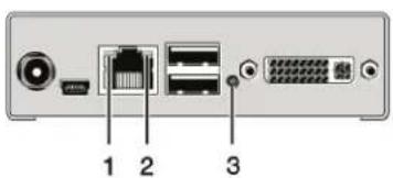
text_image
1 2 3
natural_image
Simple diagram of a rectangular object with a labeled point '3' and a small circular mark on the side (no text or symbols beyond the number)FIGURE 7-1. LEDS ON THE BACK AND FRONT.OF THE UNIT
TABLE 7-7. BLANK SCREEN TROUBLESHOOTING TIPS
| PROBLEM POSSIBLE REASON POSSIBLE SOLUTION | ||
| Monitors remain dark after switching operation | Switching to a CPU port without an active source (computer, CPU) | Switching to a CPU port with an active source (computer, CPU) |
| LED 1 ON or LED 2 OFF | Connections CON unit, matrix and CPU unit | Check connected cables and connectors. (No cable, cable break, CPU/CON unit offline, CPU/CON unit connected to the wrong port) |
| LED 3 OFF Power supply | Check power supply units and the connection to the power network | |
CHAPTER 8: TECHNICAL SUPPORT
Before contacting technical support, make sure you have read this manual and then installed and set up your Compact KVM Matrix Switch as recommended.
8.1 SUPPORT CHECKLIST
To efficiently handle your request, make sure that you have the following information available before you call:
• Company, name, phone number and email
- Type and serial number of the device (see bottom of device)
- Nature, circumstances and duration of the problem
Components included in the system (such as graphic source/CPU, OS, graphic card, monitor, USB-HID/USB 2.0 devices, interconnect cable) including manufacturer and model number
• Results from any testing you have done
Contact Black Box Technical Support at 877-877-2269 or info@blackbox
8.2 SHIPPING CHECKLIST
- To return your device, contact your Black Box Technical Support at 877-877-2269 or info@blackbox.com to obtain an RMA (Return Material Authorization) number.
- Package your devices carefully, preferably using the original box. Add all pieces that you received originally.
- Note your RMA number visibly on your shipment.
NOTE: Devices that are sent in without a RMA number cannot be accepted. The shipment will be sent back without being opened, postage unpaid.
9.1 FCC STATEMENT
This equipment has been found to comply with the limits for a Class A digital device, pursuant to Part 15 of the FCC Rules. These limits are designed to provide reasonable protection against harmful interference when the equipment is operated in a commercial environment. This equipment generates, uses, and can radiate radio frequency energy and, if not installed and used in accordance with the instruction manual, may cause harmful interference to radio communications. Operation of this equipment in a residential area is likely to cause harmful interference in which case the user will be required to correct the interference at his own expense.
Changes or modifications not expressly approved by the party responsible for compliance could void the user's authority to operate the equipment.
Shielded cables must be used with this equipment to maintain compliance with radio frequency energy emission regulations and ensure a suitably high level of immunity to electromagnetic disturbances.
All power supplies are certified to the relevant major international safety standards.
9.2 CE DECLARATION OF CONFORMITY
The Compact KVM Matrix Switch as delivered complies with the provisions of the following European Directives:
◆ 2014/30/EU Council Directive on the approximation of the laws of the Member States relating to electromagnetic compatibility
2014/35/EU Council Directive on the harmonization of the laws of the Member States relating to the making available on the market of electrical equipment designed for use within certain voltage limits.
9.3 PRODUCT SAFETY
The product safety of the devices is proven by the compliance to the following standards:
IEC 60950-1A1:2010
EN 60950-1/A12:2011/A1:2010/A11:2009
UL 60950-1-2007
CAN/CSA-C22.2 60950-1-07
9.4 WEEE
The manufacturer complies with the EU Directive 2012/19/EU on the prevention of waste electrical and electronic equipment (WEEE).
9.5 ROHS/ROHS2
This device complies with the Directive 2011/65/EU of the European Parliament and of the council of 8 June 2011 on the restriction of the use of certain hazardous substances in electrical and electronic equipment (RoHS 2, RoHS II).
10.1 VIDEO AND KVM TECHNOLOGY TERMS
AES/EBU: Digital audio standard that is officially known as AES3 and that is used for carrying digital audio signals between devices.
CATx: Any CAT5e, CAT6, CAT7 cable.
CGA: Color Graphics Adapter (CGA) is an old analog graphic standard with up to 16 displayable colors and a maximum resolution of 640 x 400 pixels.
Component Video: Component Video (YPbPr) is a high-quality video standard that consists of three independently and separately transmittable video signals, the luminance signal and two color difference signals.
Composite Video: Composite Video is also called CVBS and it is part of the PAL TV standard.
CON Unit: Component of a KVM Extender or Media Extender to connect to the console (monitor[s], keyboard and mouse; optionally also with USB 2.0 devices).
Console: Keyboard, mouse and monitor.
CPU Unit: Component of a KVM Extender or Media Extender to connect to a source (computer, CPU).
CVBS: The analog color video baseband signal (CVBS) is also called Composite Video and it is part of the PAL TV standard.
DDC: Display Data Channel (DDC) is a serial communication interface between monitor and source (computer, CPU). It allows a data exchange via a monitor cable and an automatic installation and configuration of a monitor driver by the operating system.
DisplayPort: A VESA standardized interface for an all-digital transmission of audio and video data. It is differentiated between the DisplayPort standards 1.1 and 1.2. The signals have LVDS level.
Dual Access: A system to operate a source (computer, CPU) from two consoles.
Dual Link: A DVI-D interface for resolutions up to 2560 x 2048 by signal transmission of up to 330 MPixel/s (24-bit).
Dual-Head: A system with two video connections.
DVI: Digital video standard, introduced by the Digital Display Working Group (http://www.ddwg.org). Single Link and Dual Link standards are distinguished. The signals have TMDS level.
DVI-I: A combined signal (digital and analog) that allows running a VGA monitor at a DVI-I port—in contrast to DVI-D (see DVI).
EGA: The Enhanced Graphics Adapter (EGA) is an old analog graphic standard, introduced by IBM in 1984. A DB9 connector is used for connection.
Fiber: Single-mode or multimode fiber cables.
HDMI: An interface for an all-digital transmission of audio and video data. It is differentiated between the HDMI standards 1.0 to 1.4a. The signals have TMDS level.
KVM: Keyboard, video and mouse.
Mini-XLR: Industrial standard for electrical plug connections (3-pole) for the transmission of digital audio and control signals.
Multimode: 62.5μ multimode fiber cable or 50μ multimode fiber cable.
OSD: The On-Screen Display is used to display information or to operate a device.
Quad-Head: A system with four video connections.
RCA (Cinch): A non-standard plug connection for transmission of electrical audio and video signals, especially with coaxial cables.
S/PDIF: A digital audio interconnect that is used in consumer audio equipment over relatively short distances.
SFP: SFPs (Small Form Factor Pluggable) are pluggable interface modules for Gigabit connections. SFP modules are available for CATx and fiber interconnect cables.
Single Link: A DVI-D interface for resolutions up to 1920 x 1200 by signal transmission of up to 165 MPixel/s (24-bit). Alternative frequencies are Full HD (1080p), 2K HD (2048 x 1080) and 2048 x 1152.
CHAPTER 10: GLOSSARY
Single-Head: A system with one video connection.
Single-mode: 9μ single-mode fiber cable.
S-Video (Y/C): S-Video (Y/C) is a video format transmitting luminance and chrominance signals separately. It has a higher quality standard than CVBS.
TOSLINK: Standardized fiber connection system for digital transmission of audio signals (F05 plug connection).
Triple-Head: A system with three video connections.
USB-HID: USB-HID devices (Human Interface Device) allow for data input. There is no need for a special driver during installation; "New USB-HID device found" is reported. Typical HID devices include keyboards, mice, graphics tablets and touch screens. Storage, video and audio devices are not HID.
VGA: Video Graphics Array (VGA) is a computer graphics standard with a typical resolution of 640 x 480 pixels and up to 262,144 colors. It can be seen as a follower of the graphics standards MDA, CGA and EGA.
10.2 MATRIX-SPECIFIC TERMS
Auto Disconnect: Matrix function that allows an automatic disconnect between a console and a CPU if OSD is opened via this console.
Auto Logout: Matrix function that describes the duration of inactivity after the user has been logged out from the OSD at this console.
CON Device: Logical term that summarizes several physical extenders to switch more complex console systems via matrix.
CON Timeout: Matrix function that allows an automatic disconnect of a console from the connected CPU after a predefined time.
Console ACL: Console Access Control List is a list that shows the respective switching rights for the various consoles.
CPU Auto Connect: Matrix function that allows an automatic connection establishment between a console and a random CPU that is available.
CPU Device: Logical term that summarizes several physical extenders to switch more complex CPU systems via matrix.
CPU Timeout: Matrix function that allows the user to disconnect after a predefined period of time of inactivity from the respective CPU.
EXT Unit: Part or extender board of a CON or CPU unit with a connection to the matrix. A CON or CPU unit can consist of several EXT devices.
Force Connect: Matrix function that allows you to switch a console to a CPU that is already used to take keyboard and mouse control. The console that is connected before switching loses K/M control, but keeps video.
Force Disconnect: Matrix function that allows you to switch a console to a CPU that is already used to take KVM control.
The console that is connected before switching loses complete KVM control.
Java Tool: Java based control and configuration tool for the Compact KVM Matrix Switch.
Keyboard Connect: Matrix function that allows taking over the keyboard control of an inactive console.
Macro Keys: Programmable keys that can execute a stringing together of commands to the matrix.
Mouse Connect: Matrix function that allows taking the mouse control of an inactive console.
Non-Blocking Access: Matrix configuration where no user can be disturbed by an activity of another user.
OSD Timeout: Matrix function that closes the OSD automatically after a predefined period of time of inactivity.
Release Time: Matrix function that allows a console that is connected with the same CPU to release the K/M control after a predefined time.
CHAPTER 10: GLOSSARY
NEED HELP?
LE AVE THE TECH TO US
LIVE 24/7
TECHNICAL
SUPPORT
1.8 7 7.87 7.2269
Service Mode: Defined maintenance condition that allows updating of extenders that are connected to the matrix.
Tie Line: Communication connection to and between extension modules in a network environment.
User ACL: User Access Control List is a list that shows the respective switching rights for the various users.
Video Sharing: Matrix function that allows switching from the user's console to any CPU with video.
CHAPTER 11: DISCLAIMER/TRADEMARKS
NEED HELP?
LE AVE THE TECH TO US
LIVE 24/7
TECHNICAL
SUPPORT
1.8 7 7.8 77.2 26 9
11.1 DISCLAIMER
Black Box Corporation shall not be liable for damages of any kind, including, but not limited to, punitive, consequential or cost of cover damages, resulting from any errors in the product information or specifications set forth in this document and Black Box Corporation may revise this document at any time without notice.
11.2 TRADEMARKS USED IN THIS MANUAL
Black Box and the Black Box logo type and mark are registered trademarks of Black Box Corporation.
Any other trademarks mentioned in this manual are acknowledged to be the property of the trademark owners.
NOTES
NEED HELP?
LE AVE THE TECH TO US
LIVE 24/7
TECHNICAL
SUPPORT
1.8 7 7.87 7.2269
NOTES
NEED HELP?
LE AVE THE TECH TO US
LIVE 24/7
TECHNICAL
SUPPORT
1.8 7 7.87 7.22 6 9
NOTES
NEED HELP?
LE AVE THE TECH TO US
LIVE 24/7
TECHNICAL
SUPPORT
1.8 7 7.8 77.2 26 9
NEED HELP?
LEAVE THE TECH TO US
LIVE 24/7
TECHNICAL
SUPPORT
1.87 7.8 7 7.2 269