
ME70 - Marine Radar SIMRAD - Free user manual and instructions
Find the device manual for free ME70 SIMRAD in PDF.


| Type | Scientific multibeam echo sounder system |
| Brand | Simrad |
| Model | ME70 |
| Frequency range | 70 kHz to 120 kHz |
| Number of beams | Up to 45 beams in fan plus 2 reference beams (all configurable as split beams) |
| Beam opening angles | Alongship and athwartship: selectable 2° to 20° (depending on frequency and steering) |
| Operating sector athwartship | Maximum 140° with reduced sidelobe suppression; centre angle ±45° |
| Motion compensation | Roll ±10°, Pitch ±5°, Heave |
| Sidelobe level | Less than -35 dB (configurable down to -70 dB) |
| Transducer elements | 800 individual elements |
| Transducer technology | Ceramic polymer composite |
| Transducer housing | Circular, outer diameter 677 mm, housing diameter 700 mm |
| Transceiver channels | 800 Tx and 800 Rx channels |
| Beamforming | Cluster of six computers, 1 Gb Ethernet |
| Transceiver unit dimensions | Height 1921 mm, Depth 900 mm, Width 600 mm |
| Power cabinets | 3 units, each 812 x 418 x 600 mm (HxDxW) |
| Operator station | Commercial workstation with Windows XP |
| Calibration | Included, with tungsten sphere |
| Minimum acquisition depth | Less than 1 m below transducer (depending on beam mode) |
| Data output | Continuous output of beam data for echo integration and 3D visualization |
Frequently Asked Questions - ME70 SIMRAD
User questions about ME70 SIMRAD
0 question about this device. Answer the ones you know or ask your own.
Ask a new question about this device
Download the instructions for your Marine Radar in PDF format for free! Find your manual ME70 - SIMRAD and take your electronic device back in hand. On this page are published all the documents necessary for the use of your device. ME70 by SIMRAD.
USER MANUAL ME70 SIMRAD
We are proud to introduce the world's first quantitative multibeam echo sounder for fishery research applications
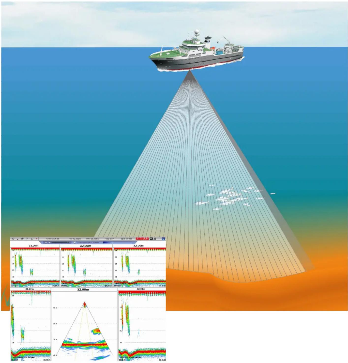
System overview
The Simrad ME70 offers quantitative data and high operational flexibility. It provides a configurable wide fan of stabilized and calibrated beams for biomass estimation, fish school characterization. and behaviour studies.
All beams can be configured as split beams providing data for single target analysis, such as target strength measurements and target tracking.
The sector of calibrated narrow split beams with low sidelobe levels and short pulse lengths allow for accurate biomass estimation very close to the bottom. The ability to adjust the athwartship centre angle of the fan enables you to use the system for studying fish close to ridges and slopes. The design also permits you to use all the beams over the full frequency range pointing in one direction for frequency comparison.
Not just an ordinary multibeam sounder
Within the bandwidth of the transducer, the limits for beam steering, and the minimum achievable beam opening, you can select the directions, frequencies, and opening angles for the beams in the Simrad ME70.
You will be able to configure the system to fit your requirements, and the system will provide you with a real-time display for quality control of the current data acquisition.
The system configuration can be tailored to any user requirements, allowing for choice of beamwidths as well as transmission modes.
Low sidelobe levels and beam interleakage
Low sidelobes are important for two reasons. The obvious one is to avoid that strong targets in side lobes are mistaken for weak targets in the main lobe. Secondly, you do not wish to see strong bottom echoes from the sidelobes. Even the vertical receiver beam may benefit from low sidelobes
Key points
- The Simrad ME70 operates in the 70 to 120 kHz frequency range.
- The Simrad ME70 provides a configurable acoustic fan containing 3 to 45 stabilized beams.
- All beams can be configured as split beams.
- Calibration software included.
- Minimum beam opening is 2^ depending on operational frequency and steering.
- 140^ maximum total swath width.
- The athwartship centre angle of the fan can be adjusted from +45^ to -45^ .
- Minimum acquisition depth is less than 1 m below the transducer depending on beam mode configuration.
- Sidelobe levels and beam interleakage are adjustable from -35 to -70 dB depending on beamwidth and frequency configuration.

natural_image
3D rendering of a red cylindrical mechanical component with bolt holes (no text or symbols)in case of a sloping bottom.
Very low two-way sidelobe levels are obtained by using two-way side lobe suppression. Very low beam interleakage is obtained by using Frequency Rotated Directional Transmission (FRDT) where the frequency band is distributed over all the beams.
Since each beam has its own frequency and the fan width is configurable, the design also allows you to use all the beams over the full frequency range pointing in one direction for frequency analysis of targets.
Calibration
A calibration utility is implemented as a special built-in function in the Simrad ME70 system. Each beam configuration of interest can be calibrated using a reference target located under the ship.
Individual gain parameters for each beam are adjusted to provide calibrated target strength and volume backscattering strength measurements.
Splitbeam configuration
All beams can be configured as split beams. In addition, two adjustable reference split beams are available. These allow you to compare ME70 data with data from other split beam systems, for example the EK60. The reference beams can for example have 7x7 degrees opening angles, and operate on 70 and 120 kHz.
The data from the individual split beams are presented in the same way as on other Simrad scientific sounders.
Data output
It is possible to set up continuous output of all beam data. This can be used for echo integration and 3D visualisation. The output data for each beam include for example:
• non-TVG compensated sample power and sample angle
• 20 log R compensated sample Sv
• 40 log R compensated sample TS
• 40 log R compensated single target detections
- Detected depth
It is also possible to output the element data for post processing and analysis purposes.
Remote operation
Remote systems, such as data loggers and external post-processing systems, can subscribe to data and parameters from the Simrad ME70. The parameters can also be queried and defined by the remote system. In this way the communication between the ME70 and the remote system can become an efficient, configurable, two-way communication.

line
| Time | Depth (m) | | ---------- | --------- | | 09:36:51 | 10 | | 09:40:16 | 10 | | 09:35:58 | 20 | | 09:40:16 | 30 | | 09:35:37 | 40 | | 09:40:16 | 10 |This capture provides a typical presentation of fish schools. You can see five of the 31 beams, as well as the fan presentation. The menu is hidden from view. (Data kindly provided by Ifremer, France.)

flowchart
graph TD
    A["Beamforming computers"] <--> B["Network controller"]
    B <--> C["TRXU Transceivers"]
    D["Operator station"] --> B
    E["Power cabinets"] --> C
    F["CD10102C"] --> G["Red cylindrical device"]
System diagram
Operator station
The operator station comprises a computer running Windows XP® operating system. It is connected to the ship's network, and can communicate with external post-processing applications.
Transceiver
The transceiver circuitry comprises three transceiver shelves, a network controller, and six beamforming computers.
Power Cabinets
Three separate power cabinets provide the operation power to the TRXU Transceivers.
Transducer
The transducer array is mounted in a circular housing. Its outer diameter is 677 mm. The array contains 800 individual elements.
System
• Scientific multibeam echo sounder
Acoustics
Frequency range
- 70 kHz to 120 kHz
Beams
- Organisation: Fan
• Total number of beams: Maximum 45 beams in fan plus two reference beams
• Number of split beams: Maximum 45 split beams in fan plus two reference beams
Beam opening angles
- Alongship: Selectable 2^ to 20^
- Athwartship: Selectable 2^ to 20^
- Opening angles depend on beam steering and frequency.
Operating sectors
- Athwartship: 60^ Maximum 140^ with reduced sidelobe suppression
- Athwartship sector centre angle: ± 45^
- Alongship sector centre angle: ± 5^
Motion compensation
- Roll: ± 10^
- Pitch: ± 5^
- Heave
Sidelobe and beam
interleakage
- Alongship: Less than -35 dB
- Athwartship: Less than -35 dB
- Configurable depending on beamwidth and frequency configuration.
Transmission
• FM with pulse duration 128 to 5120 μs
• CW with pulse duration 64 to 5120 μs
- Source level: > 225 dB (depending on beam opening and frequency)
Receiving
- Receiver dynamic range: 150 dB (instantaneous)
Calibration
• Calibration software included
• Target: Tungsten sphere
Hardware
Transducer
• Number of elements: 800
• Technology: Ceramic polymer composite
- Housing: Circular
• Housing diameter: 700 mm
Transceiver Unit
• Individual Tx channels: 800
• Individual Rx channels: 800
- Beamforming: Cluster of six computers
- Communication: 1 Gb Ethernet
• Physical dimensions:
Height: 1921 mm
Depth: 900 mm
Width: 600 mm
Power cabinets
• Quantity: Three cabinets
• Physical dimensions:
Height: 812 mm
Depth: 418 mm
Width: 600 mm
Operator Station
• Type: Commercial workstation
- Operating system: Microsoft® Windows XP®
Optional systems
- Element data logger
- Bathymetric processing system

natural_image
Yellow industrial robotic arm with red base, partially submerged in water (no visible text or symbols)The transducer array set up for test and calibration at Simrad's laboratory
Note that technical specifications can be altered without prior notification!
(855-165184 / Rev.C / November 2006)
- System overview
- Not just an ordinary multibeam sounder
- Low sidelobe levels and beam interleakage
- Key points
- Calibration
- Splitbeam configuration
- Data output
- Remote operation
- System diagram
- Operator station
- Transceiver
- Power Cabinets
- Transducer
- System
- Acoustics
- Frequency range
- Beams
- Beam opening angles
- Operating sectors
- Motion compensation
- Sidelobe and beam
- interleakage
- Transmission
- Receiving
- Hardware
- Transceiver Unit
- Optional systems
Brand : SIMRAD
Model : ME70
Category : Marine Radar