
SL35 - Marine Radar SIMRAD - Free user manual and instructions
Find the device manual for free SL35 SIMRAD in PDF.


| Product Type | Hull Mounted Mechanical Scanning Sonar |
| Model | Simrad SL35 |
| Frequency Options | 90 kHz or 160 kHz |
| Operating Range | 5 m to 1250 m (detection range: 750 m for 90 kHz, 450 m for 160 kHz) |
| Transmit Power | 1.2 kW |
| Transducer Beam | 8° x 8° cone, side lobe -25 dB |
| Tilt Range | Upward: 0° to +10°; Downward: 0° to -90° |
| Stabilization (Optional) | Pitch and roll compensation ±30° |
| Display Modes | Horizontal, Bow Up, Vertical Fan, Sounder, Horizontal with History, Horizontal with Real Time Vertical Strata |
| User Modes | 4 customizable user setups |
| Control Panel | Flush mount, backlit buttons, integrated roller ball, interface unit |
| Processor Unit | HP Compaq ruggedized, Windows XP Professional, 40 GB HDD, 2 VGA outputs, LAN, USB, RS232 |
| Power Input (Processor) | 115/240 VAC, 50/60 Hz, <5 A |
| Power Input (Control Panel) | 115/240 VAC, 50/60 Hz, <5 A |
| Power Input (Hoist Unit) | 24/32 VDC, <10 A |
| Hoist Travel | 250 mm or 400 mm stroke, hydraulic ram |
| Raising Time | 10 seconds |
| Maximum Raising Ship Speed | 15 knots |
| Sonar Dome Size | 8 inches |
| Weight (Hydraulic Actuator) | 17 lb (7.7 kg) for 250 mm stroke, 18 lb (8.2 kg) for 400 mm stroke |
| Data Input/Output | NMEA 0183 (RS232) |
| Operating System | Microsoft Windows XP Professional |
| Warranty | 12 months underwater equipment, 24 months surface equipment |
Frequently Asked Questions - SL35 SIMRAD
User questions about SL35 SIMRAD
0 question about this device. Answer the ones you know or ask your own.
Ask a new question about this device
Download the instructions for your Marine Radar in PDF format for free! Find your manual SL35 - SIMRAD and take your electronic device back in hand. On this page are published all the documents necessary for the use of your device. SL35 by SIMRAD.
USER MANUAL SL35 SIMRAD
SL 30/35 HULL SONAR OPERATORS MANUAL
974-25007001
Issue 2.0 September 2003

Kongsberg Simrad Mesotech Ltd Products Warranty Policy
Effective January 1, 2003
Kongsberg Simrad Mesotech Ltd. Warrants each new product (equipment) to be free of defects caused by faulty materials or poor workmanship for a period of twelve (12) months for underwater equipment and twenty-four (24) months for surface equipment from date of installation by an authorized Kongsberg Group Company, Simrad Distributor, Dealer or Agency. The warranty does not apply to defects caused by, force majeure events or misuse, including water damage to the surface equipment, improper maintenance and installation, including excessive wear and tear for which Kongsberg Simrad Mesotech Ltd. Is not responsible.
Underwater Equipment:
- Warranty for Underwater Equipment that is hull mounted, such as those mentioned below, will be assessed on a case-by-case basis but shall generally not be covered by the warranty:
• Hull Units, Sonar Dome Assemblies and Echo Sounder Transducers
• Transducer Units, Speed, Temperature and Depth Sensors
Note: Additional expenses connected with replacement of transducers, such as dry- docking and diving, are not covered by this warranty.
Warranty on Parts or Equipment Replacement:
- It is at the sole discretion of Kongsberg Simrad Mesotech Ltd. to either repair or replace any unit/part that fails within the limits of the Warranty Policy.
- The Warranty Policy is only valid on new equipment
- Replacement of parts, components, and/or PCB Boards during a warranty repair does not extend the original warranty period.
Consumable Materials:
- Consumable materials, such as lamps, fuses, o-rings, gaskets and batteries, shall not be replaced free of charge.
Warranty Service:
- Warranty service is available worldwide through authorized Kongsberg Group Companies, Simrad Distributors, Dealers or Agencies. When requesting warranty service, you must supply the following information:
- Proof of purchase.
- Equipment part number and serial number.
-
Fault description and all relevant vessel information.
-
Labour cost for the repair or replacement of any products/equipment and/or module/parts is the responsibility of the servicing agent or dealer.
- All customs duties, brokerage charges and local taxes, overtime, expenses for meals, tools, launch services, ferries, lodgings, normal adjustments and routine maintenance are not covered by this warranty policy.
DISCLAIMER
- Maximum liability shall not, in any case, exceed the contract price of the products claimed to be defective.
- Consequential damages including, but not limited to, any loss of profit, property damage or personal injury, are not covered by the warranty policy.
- This equipment is not certified or approved for navigation and/or safe-navigation practices, and is not to be used for navigation purposes under any circumstances.
LIST OF CONTENTS
Part 1....System Familiarization
Part 2....System Description
Part 3....Control Panel Operation and Display Modes
Part 4....Menu and Software Description
Part 5 ...... Selecting Settings
Part 6 SL 35 Installation, Start-Up and Test
Part 7 SL 30 Installation, Start-Up and Test
Part 8 Maintenance
Part 9 .... Attachments and Drawings
MODIFICATION RECORD
SL 30/35 HULL SONAR OPERATORS MANUAL
974-25007001
Issue: 2.0
September 2003
Issue
No. Date Initial Comments
1.0 05.02 L.F. First Release
2.0 09-03 L.F. Second Release
To assist us in making improvements to the product and this document, Kongsberg Simrad Mesotech welcomes comments and constructive criticisms. Please send all such comments, in writing or by e-mail, to:
Kongsberg Simrad Mesotech Ltd.
Documentation Department
1598 Kebet Way
Port Coquitlam, BC V3C 5M5
CANADA
E-mail: vancouver.sales@kongsberg-simrad.com
PART 1
The SIMRAD SL 30/35 Hull Sonar Series is a short range, mechanical scanning sonar designed for small and medium sized purse seiners and trawl fishing vessels. The system provides real time images from the sonar dome to the bridge, thus maximizing the best possible presentation on a high-resolution colour monitor, providing the operator with 6 different display modes and 4 customized user modes, giving a flexible choice for a large range of user applications.
The SL 303/35 Sonar allows the operator to monitor the complete operation, by displaying individual fish school target locations in the Horizontal Plane. In addition to the Horizontal plane, the SL 30/35 Sonar provides a Vertical Fan mode, specially made for trawling, where a complete overview of the Horizontal and Vertical Planes are presented.
The sonar beam can be horizontally trained 360° and 180° in the Vertical Plane. The automatic search features and full -90° tilt capability ensure maximum control during the tow and/or pursing. The active motion compensation for pitch and roll and the audio speaker are optional.
The SL 30/35 Sonar is a modular system. It is operated with ease through a direct access Control Panel with an integrated mouse.
1.1.1 Equipment Configuration
A complete SL 30/35 Hull Sonar consists of:
- Simrad LCD or VGA Display Monitor. (Optional)
• SL 30/35 Processor Unit.
• SL 30/35 Control Panel and Interface Module.
• SL 30 or 35 Transceiver Assembly. - SL 30 or 35 Sonar Dome Assembly, Frequency, 90kHz or 160kHz.
- SL 35 Lower and Raise unit, travel, 250 millimeters or 400 millimeters.
• SL 35 Shaft Length: 2.4m, or 3.0m,.
• SL 30/35 Motion Sensor Option.
• SL 30/35 Built-in Internal Audio Speaker, (Optional External Audio Speaker).
• SL 35 Standard Installation Materials
Important notice:
Windows, Windows NT, Windows 2000 and Windows XP are either registered trademarks or trademarks of Microsoft Corporation in the United States and/or other countries.
1.1.2 System Diagram
SL 35 Hull Mounted Sonar & SL 30 Catch Sonar Interconnection System Diagram

flowchart
graph TD
    A["LCD Monitor"] --> B["Processing Unit"]
    C["Optional LCD Monitor"] --> B
    B --> D["Com 1, RS232 Cable (2m)"]
    B --> E["PS 2 KBD/Mouse Cables (2m) each"]
    B --> F["SL 30 Interface Unit"]
    D --> G["Power Input 110/220 VAC +/- 10%"]
    E --> H["Power input 110/220 VAC +/- 10%"]
    F --> I["Power input 110/220 VAC +/- 10%"]
    G --> J["Power Input 110/220 VAC +/- 10%"]
    H --> K["Power Input 110/220 VAC +/- 10%"]
    I --> L["Power Input 110/220 VAC +/- 10%"]
    J --> M["Power Input 110/220 VAC +/- 10%"]
    K --> N["Power Input 110/220 VAC +/- 10%"]
    L --> O["Power Input 110/220 VAC +/- 10%"]
    M --> P["Power Input 110/220 VAC +/- 10%"]
    N --> Q["Power Input 110/220 VAC +/- 10%"]
    O --> R["Power Input 110/220 VAC +/- 10%"]
    P --> S["Power Input 110/220 VAC +/- 10%"]
    Q --> T["Power Input 110/220 VAC +/- 10%"]
    R --> U["Power Input 110/220 VAC +/- 10%"]
    S --> V["Power Input 110/220 VAC +/- 10%"]
    T --> W["Power Input 110/220 VAC +/- 10%"]
    U --> X["Power Input 110/220 VAC +/- 10%"]
    V --> Y["Power Input 110/220 VAC +/- 10%"]
    W --> Z["Power Input 110/220 VAC +/- 10%"]
    X --> AA["Power Input 110/220 VAC +/- 10%"]
    Y --> AB["Power Input 110/220 VAC +/- 10%"]
    Z --> AC["Power Input 110/220 VAC +/- 10%"]
    AA --> AD["Power Input 110/220 VAC +/- 10%"]
    AB --> AE["Power Input 110/220 VAC +/- 10%"]
    AC --> AF["Power Input 110/220 VAC +/- 10%"]
    AD --> AG["Power Input 110/220 VAC +/- 10%"]
    AE --> AH["Power Input 110/220 VAC +/- 10%"]
    AF --> AI["Power Input 110/220 VAC +/- 10%"]
    AG --> AJ["Power Input 110/220 VAC +/- 10%"]
    AH --> AK["Power Input 110/220 VAC +/- 10%"]
    AI --> AL["Power Input 110/220 VAC +/- 10%"]
    AJ --> AM["Power Input 110/220 VAC +/- 10%"]
    AK --> AN["Power Input 110/220 VAC +/- 10%"]
    AL --> AO["Power Input 110/220 VAC +/- 10%"]
    AM --> AP["Power Input 110/220 VAC +/- 10%"]
    AN --> AQ["Power Input 110/220 VAC +/- 10%"]
    AO --> AR["Power Input 110/220 VAC +/- 10%"]
    AP --> AS["Power Input 110/220 VAC +/- 10%"]
    AQ --> AT["Power Input 110/220 VAC +/- 10%"]
    AR --> AU["Power Input 110/220 VAC +/- 10%"]
    AS --> AV["Power Input 110/220 VAC +/- 10%"]
    AT --> AW["Power Input 110/220 VAC +/- 10%"]
    AU --> AX["Power Input 110/220 VAC +/- 10%"]
    AV --> AY["Power Input 450 mm Travel"]
    AW --> AZ["450 mm Travel"]
    AX --> BA["450 mm Travel"]
    AY --> BB["450 mm Travel"]
    AZ --> BC["450 mm Travel"]
    BA --> BD["450 mm Travel"]
    BB --> BE["Sonar Dome 90kHz or 160kHz"]
    BC --> BF["Sonar Dome 90kHz or 160kHz"]
    AD --> BG["Catch Sonar Dome 90kHz or 160kHz"]
1.1.3 Display
The display monitor for the SL 30/35 Sonar can be either a VGA “CRT” or LCD Simrad ruggedized monitor, but any commercially available monitor may be used. In order to have the full benefit of high resolution, you should use a Simrad LCD Monitor.
1.1.4 Processor Unit
The SL 30/35 Sonar Processing Unit is a ruggedized computer, which can interface with other auxiliary equipment (Control Panel, Interface Unit, GPS, Echo Sounder and Trawl Systems, etc.). The processor unit runs on the Microsoft Windows XP Operating System. The SL 30/35 Sonar System software provides a mechanism for the sonar operation. It is operated through the Main Control Panel to enable the sonar selection, tilt, range, gain and cursors; moving the mouse pointer over the toolbar will allow the operator to perform certain operations with a simple mouse click. A flush mounted Control Panel is provided to simplify the operation of the system.
The rear panel of the processing unit contains the connectors for AC and DC power, Monitor port, two RS232 Serial Ports, Keyboard, Mouse, Printer, Network LAN and USB port. The Network LAN port can be used to connect a remote workstation, or to download data from the processing unit.
Note: A security key (or "dongle") must be attached to the parallel port to enable full operation of the system.
1.1.5 Control Panel and Interface Unit
The SL 30/35 Control Panel contains all necessary control functions for operating the sonar. As some of the functions are used more frequently than others, the control buttons are arranged in function groups, as Sector Train, Tilt, Scan Speed, Range, Display Mode, User Setting and Utilities. The Power ON and OFF buttons, the Lower and Raise buttons are also provided for on the SL 35 Hoist Control.
Note: All sonar operations may also be controlled from the integrated roller ball, or from an optional remote standard mouse.
The SL 30/35 Interface Unit is incorporated into the Control Panel assembly, providing the interface telemetry communication between the Processing Unit and the Transceiver Unit in the sonar room.
Note that only one signal cable is used for communication between the Interface Unit and the Transceiver Unit.
1.1.6 Sonar Room Unit
The Transceiver Unit and Lower/Raise Unit are located in the sonar room, mounted to the tank flange.
The Hull Unit sonar dome is lowered 250 millimeters or 400 millimeters below the ship's hull. In case of a power failure the dome assembly will automatically retract back up into the sonar tank.
Note: The sonar dome can be manually raised by means of a hand pump.
The optional motion sensor for the electronic stabilization of the sonar beams is also located in the sonar room. A 10 meters interconnection cable is supplied.
WARNING!!
If the sonar dome hits a large object or the bottom, the dome shaft may be bent, or in the worst case it can be broken off. A broken sonar dome may cause water leakage at the top of the shaft. To prevent large leakages in such a case, DO NOT raise the sonar dome shaft to the upper position. It is therefore of great importance to have a good pump and warning system in the sonar room.
DISCLAIMER
This equipment is not certified or approved for navigation and/or safe-navigation practices and is not to be used for navigation purposes under any circumstances.
1.2 SL 30/35 TECHNICAL SPECIFICATIONS
- Processing Unit
Operating System: MS Windows XP Professional
40GB Hard Drive
2 SVGA Monitors output
Sound Card
Network LAN Port
4 USB Ports and 2 RS232 Serial Ports
Built-in Audio Speaker
Power input: 115/240VAC, 50/60Hz, +/- 10%, (<5A)
- Data Input/output
NMEA 183 format (RS232)
- Range
Operating Range: 5 meters to 1250 meters
Detection Range: 750m for 90kHz; 450m for the 160kHz Dome
- Tilt
Upward: From 0^ to +10^
Downward: From 0^ to -90^
- Stabilization
Pitch and Roll: +/- 30°
- Operating Panel
Flush Mounted
Integrated Interface Unit
Power input: 115/240VAC, 50/60Hz, +/- 10%, (<5A)
Hull Unit
Hoist Unit: Hydraulic Ram
Travel: 250mm or 400mm Stroke
Raising Time: 10 Seconds
Maximum Raising Ship Speed: 15 Knots
- Transceiver Unit
Frequency: 90kHz or 160kHz
Transmit O/P Power: 1.2 kW
Power input: 24/32VDC, +/- 10%, for Hoist Unit Only (<10A)
Sonar Dome Size: 8 inches
- Sonar Dome Unit
Transducer Beam: Cone 8° X 8°, Side Lobe: -25dB
Installation Trunk: Not DnV approved Trunk. (In process)
- Options:
LCD Monitor
Motion Sensor
External Audio Speaker
UPS Input Power Supply
PART 2
SYSTEM DESCRIPTION
2. SYSTEM DESCRIPTION ......2.3
2.1 INTRODUCTION 2.3
2.1.1 Basic Principles ......2.3
2.1.2 Determining Target Position 2.3
2.1.3 Forming an Image....2.3
2.1.4 Wheelhouse Units Description....2.4
2.1.4.1 Display Monitor....2.4
2.1.4.2 Processor Unit....2.4
2.1.4.3 Control Panel....2.5
2.1.4.4 Interface Unit....2.5
2.1.4.5 Interconnect Cables....2.5
2.1.5 Sonar Room Units Description....2.5
2.1.5.1 Transceiver Unit....2.6
2.1.5.2 Lower and Raise Unit....2.6
2.1.5.3 Hull Sonar Dome Unit 2.6
2.1.5.4 Tank Flange Assembly 2.6
2.1.5.5 Interconnect Cables....2.7
2.1.6 Options 2.7
2.1.6.1 Motion Sensor....2.7
2.1.6.2 Audio Warning Speaker....2.7
2.1.7 Remarks 2.7
2.1.8 Warning....2.8
2.1.9 Copyright 2.8
2. SYSTEM DESCRIPTION
2.1 INTRODUCTION
This section explains the theory of operation of the SL 30/35 Mechanical Scanning Sonar System.
2.1.1 Basic Principles
• Sound waves travel very efficiently through water.
- A sound pulse can be projected through water in a controlled direction with the sonar transducer.
- An object in the path of the projected sound pulse will reflect some sound pulse back toward the sonar transducer.
- The speed of the sound pulse projected through the water can be predicted for given conditions.
2.1.2 Determining Target Position
The SL 30/35 scanning sonar processor measures the time from the start of the sound pulse projected through water, to the reception of the sound pulse reflected back to the sonar transducer. The measured time is then converted to distance by using the speed of sound through water.
Since the sound pulse is projected in a known direction, the bearing of the reflected object is also known. This makes it possible to locate the object with respect to the sonar transducer; the information will be used to plot the position of the reflected target on a video graphic display monitor.
2.1.3 Forming an Image
The sound pulse projected will be attenuated as it travels through the water from the transducer to the target and back. Much of this attenuation is a predictable function of the total time or the distance the sound pulse traveled through water. Increasing the receiving gain with time can compensate for this decrease in the signal level. This is done automatically in the sonar with a Time Varying Gain circuit.
After the TVG correction, the absolute levels of the received signals will be determined by the acoustic response of the reflecting target.
The sonar processor system repeatedly measures the TVG corrected target levels by digitizing a sequence of samples after each sound pulse transmission. Each sample is then plotted on the video display at the appropriate position according to its range and bearing. The level of the target strength sample determines the color used to plot each sample.
The process can be repeated with the transducer pointed in different directions, forming an image of a large area of the bottom and displaying it on the video screen.
2.1.4 Wheelhouse Units Description
The following paragraphs will describe the key features of the Wheelhouse Units of the SL 30/35 Hull Sonar.
2.1.4.1 Display Monitor
The display monitor required for the SL 30/35 can be either a VGA “CRT” type or any commercial LCD monitor. In order to have the full benefit of high resolution, we recommend that you select the Simrad ruggedized LCD colour monitor. The Simrad colour monitors are available in two sizes, 18" and 20". The monitor can be desk, ceiling, or flush mounted into the bridge console.
The Simrad LCD monitor will run on 110/240VAC, 50/60Hz or on 24VDC, +/- 10%. All mounting hardware is included.
2.1.4.2 Processor Unit
The processor unit is a ruggedized HP "Hewlett Packard" Compaq Processing Unit designed for use in a marine environment. The processor unit runs on the Microsoft Windows XP Professional Operating System.
In the event that you have a problem with the HP computer we recommend that you contact your Simrad dealer or Agent to assist you in solving the problem.
Hewlett Packard Customer Center can help you solve hardware issues related to HP products and, if necessary, initiate the appropriate service procedures. In the U.S.A., telephone support is available 24 hours a day, seven days a week. Elsewhere, in the world, it is available during normal office hours.
The HP Customer Care Centers are listed in the HP Warranty and Support Guide included with the computer.
Note: If the Hewlett Packard Customer Center can not help you, all warranty and service requirements are also supplied by the Simrad Dealers, or Simrad Agents.
2.1.4.3 Control Panel
The SL 30/35 Control Panel contains all of the most frequently used control buttons required to operate the sonar. The sonar can also be operated using the integrated roller ball and the on-screen menus and toolbars. Note that the integrated roller ball with its left and right buttons eliminate the need for an external mouse.
All buttons are back-lit for night operation. An automatic dimmer is incorporated in the panel, eliminating the need to raise or lower the intensity of the back illumination.
An external PC keyboard connector is also provided for use during software maintenance or upgrading.
The SL 30/35 Control Panel is designed for durability and water resistance. The unit can easily cleaned with a soft cloth dampened with soap and water only.
Details of operation are described in Part 3.
2.1.4.4 Interface Unit
The Interface Unit is incorporated into the Control Panel Assembly. It consists of an internal 24VDC Power Supply, the RS 232 Interface, the Control Panel keyboard interface and the Sonar Telemetry Translation Module (TTM) assembly PCB.
2.1.4.5 Interconnect Cables
The interconnection cables are pre-made to specific length. The RS232 and the PS2 mouse/keyboard cables are 2 meters in length. The transceiver cable to the Control Panel is available in 4 lengths: 15 meters, 30 meters, 50 meters and special order at 100 meters. The power input cable is 2.5 meters in length.
2.1.5 Sonar Room Units Description
The following paragraphs will explain the key features of the Sonar Room Hull Unit of the SL 30/35 Sonar.
2.1.5.1 Transceiver Unit
The Transceiver Unit is mounted on the tank flange in a standard installation, but can also be bulkhead mounted if required. The maximum Sonar Dome cable length permissible is 5.1 meters depending on the shaft length used during the installation.
The Transceiver Unit contains the receiver and transmitter PCB assembly and the lower and raise PCB assembly. A safety power ON/OFF switch is also provided so power can be shut off when working on the lower and raise assembly. The transceiver assembly is splash proof to protect the electronics circuits from water.
Note: The safety power ON/OFF switch is not required for the SL 30 Sonar.
2.1.5.2 Lower and Raise Unit
The SL 35 Lower and Raise Unit is a self-contained hydraulic assembly. Installation is simple and only requires the fitting of 2 clevis pins and connection of the power cable from the Transceiver Unit.
The travel length is available in two sizes, 250 millimeters and 400 millimeters depending on the installation requirement.
2.1.5.3 Hull Sonar Dome Unit
The Hull Sonar Dome unit is available in two frequencies, 90kHz and 160 kHz. The cable length is available in 4.5 meters for a 2.4 or 3 meter shaft and 5.1 meters with a 3.6 meters optional shaft. Special attention must be paid to matching cable and shaft lengths when ordering the system.
Note: The SL 30 Catch Sonar Dome comes with a standard 5 meter cable length.
2.1.5.4 Tank Flange Assembly
The SL 35 Tank Flange Assembly main body is cast in ASTM A536, 60-40-18 Ductile Iron. Special mounting pads and a guide are incorporated into the flange. The shaft bearing is made of SEA 660 Bearing Bronze. Special attention was given during the design to the seal and shaft packing in order to prevent water leakage into the sonar room. A zinc anode is also installed on the tank flange, to reduce electrolysis.
Note: The Tank Flange Assembly is not required for the SL 30 Dome; all flanges are serial-numbered.
2.1.5.5 Interconnect Cables
The only interconnection cable supplied with the transceiver is the 2.5 meters power input cable. All other cables are supplied with the other units.
2.1.6 Options
The following paragraph explains the key features of the Optional Units of the SL 30/35 Hull Sonar.
2.1.6.1 Motion Sensor
The Motion Sensor unit will compensate +/- 30 degrees for the pitch and roll of the fishing vessel. A 10 meter interconnection cable and mounting hardware is supplied when you purchase the Sensor.
2.1.6.2 Audio Warning Speaker
The Audio Warning Speaker is built into the Processor Unit. If you require an external audio speaker, You may purchase it locally. The audio speaker connects to the rear of the Processing Unit
2.1.7 Remarks
Further information about the SL 30/35 system may be found in the following manual.
This Operator and Installation Manual is intended for the design and installation engineers at the shipyard. On completion of the installation, this manual must be kept on the vessel for reference purposes during system maintenance.
Kongsberg Simrad Mesotech Ltd. makes every effort to ensure that the information contained within this manual is correct. However, our products are continuously being improved and updated, so we cannot assume liability for any errors that may occur.
Note: All specifications are subject to change without notice.
2.1.8 Warning
The product to which this manual applies must only be used for the purpose for which is it was designed. Improper use or maintenance may cause damage to the product or injury to personnel. The user must be familiar with the contents of the appropriate manual before attempting to operate or work on the product.
Kongsberg Simrad Mesotech Ltd. disclaims any responsibility for damage or injury cause by improper installation, use or maintenance of the product.
2.1.9 Copyright
The information contained within this document remains the sole property of Kongsberg Simrad Mesotech Ltd. No part of this document may be copied or reproduced in any form or by any means, and the information contained within is not to be communicated to a third party, without the prior written consent of Kongsberg Simrad Mesotech Ltd.
DISCLAIMER
This equipment is not certified or approved for navigation and/or safe-navigation practices and is not to be used for navigation purposes under any circumstances.
PART 3
SL 30/35 CONTROL PANEL
3. SL 30/35 CONTROL PANEL OPERATION....3.3
3.1 INTRODUCTION ....3.3
3.2 CONTROL PANEL....3.3
3.3 MAIN POWER SWITCH....3.4
3.3.1 Power ON/OFF Buttons....3.4
3.3.2 Sonar Dome Transducer Buttons....3.5
3.3.3 Sonar Settings Button....3.5
3.3.4 Roller Ball and Mouse Buttons....3.6
3.3.5 Sonar Selection Buttons....3.6
3.3.6 Range Buttons....3.7
3.3.7 Gain Buttons....3.7
3.3.8 Scan Buttons 3.8
3.3.9 Tilt Buttons....3.9
3.3.10 Sector Control Buttons 3.9
3.3.10.1 Move Sector Left Button 3.10
3.3.10.2 Move Sector Right Button....3.10
3.3.10.3 Narrow Sector Button....3.10
3.3.10.4 Widen Sector Button....3.10
3.3.11 Sector Aiming Mode Buttons....3.11
3.3.12 Utilities Buttons....3.12
3.3.12.1 Off Center Button....3.12
3.3.12.2 Zoom Button....3.12
3.3.12.3 Stabilize Button....3.13
3.3.12.4 Speaker Button....3.13
3.3.13 Target Track and Lock Buttons 3.13
3.3.14 Auto and Manual Search Buttons....3.14
3.3.15 Symbol Buttons....3.15
3.3.15.1 Latitude / Longitude Button....3.15
3.3.15.2 Event Mark Button 3.15
3.3.15.3 Cursor Buttons....3.16
3.3.16 User Buttons .... 3.17
3.3.17 Display Mode Buttons....3.17
3.3.17.1 Horizontal Display Mode Button....3.18
3.3.17.2 Bow Up Display Mode Button....3.18
3.3.17.3 Vertical Fan Mode Button....3.18
3.3.17.4 Sounder Mode Button....3.19
3.3.17.5 Horizontal Mode with History Mode button....3.19
3.3.17.6 Horizontal Mode with Real Time Vertical Strata Mode Button.....3.19
3.3.18 RX and TX Indicator LED....3.20
3.3.19 Alarm Indicator LED 3.20
3.3.20 Keyboard (KBD) External Plug-in 3.20
3.3.21 Panel Light Dimmer Sensor....3.21
3.3.22 Menu Description 3.21
3. SL 30/35 CONTROL PANEL OPERATION
3.1 INTRODUCTION
The SL 30/35 Sonar uses a Control Panel for the most frequently needed adjustments and a software menu system for less frequently needed controls. This chapter describes how to use the Control Panel to operate the sonar.
3.2 CONTROL PANEL

A thorough understanding of the system functions and controls is necessary to optimize the overall performance. Sonar conditions vary, sometimes drastically, and it is not possible to identify proper settings that will provide the best sonar image at all times.
Careful study of the information in this manual is highly recommended, preferably while exploring the sonar's various functions. System operation is a dynamic activity requiring regular adjustment and fine-tuning to achieve the best possible results under varying environmental conditions.
The Control Panel Buttons are described in the following paragraphs.
3.3 MAIN POWER SWITCH
The Main Power Switch controls power to the Interface Unit, the Sonar Transceiver Unit, the hull Transducer Dome Assembly and the hoisting and lowering unit of the hull transducer dome.
Note: When the SL 30/35 System is supplied with a HP/PC Processing Unit, power must be turned on separately.
3.3.1 Power ON/OFF Buttons

Press the Power ON button for approximately two seconds to power up the sonar. The adjacent green LED will light up and remain illuminated indicating that power has been supplied to the sonar and the system is ready for operation.
Press the Power OFF button to remove the power to the sonar. The adjacent red LED will light up and remain illuminated indicating that power has been removed.
Note: The Hull sonar dome transducer unit will automatically retract into the tank if Power is turned OFF, or if a loss of Power is detected. The green LED adjacent to the UP Transducer Arrow button will light, indicating that the hull sonar dome transducer is retracted into the tank and will remain illuminated.
3.3.2 Sonar Dome Transducer Buttons

Press the UP Transducer Arrow button to raise the sonar dome to its upper position. The middle yellow LED will blink while the sonar dome is being raised. The upper green LED will light and remain illuminated when the sonar dome has reached the full up position and is housed safely inside the hull of the vessel.
Press the DOWN Transducer Arrow button to lower the sonar dome into its down position. The middle yellow LED will blink while the sonar dome is lowering. The lower green LED will light and remain illuminated when the sonar dome has reached the full down position.
When the Power is turned off or if a power failure is detected, the sonar dome will automatically retract safely inside the hull of the vessel and the upper green LED will remain illuminated. If no Transducer LED's are illuminated while the power has been turned OFF, this indicates that the sonar dome has not been retracted safely into the hull of the vessel.
3.3.3 Sonar Settings Button

Press the Sonar Settings Button to display or hide the Header Menu at the top of the display. Use the roller ball to move the cursor over one of the Header Menu and click
the "L" button (left mouse button). The Header Menu allows quick access to several features that do not have a dedicated icon or button on the Control Panel.
3.3.4 Roller Ball and Mouse Buttons


The Roller Ball (Trackball), "L" (left mouse button) and the "R" (right mouse button) allow you to move the mouse cursor and control the system by means of the menu system and Tool Bar system on the display.
3.3.5 Sonar Selection Buttons

You do not need to use the Sonar Selection buttons if you only have one sonar hull unit. These buttons are provided to allow you to select the active sonar when two sonar hull units have been installed; for example: one SL 35, 90 kHz sonar and one SL 35, 160 kHz sonar.
Press the Sonar 1 button or the Sonar 2 button to select the sonar you want to control.
Note: If you only have a single sonar installed on the vessel, sonar 1 will be automatically selected. If a second sonar is installed on the vessel, sonar 1 will be automatically selected during the power-up.
3.3.6 Range Buttons

The Range Buttons control the Horizontal and the Vertical range of the sonar. Use the roller ball and move the mouse cursor over the sonar display you want to control and click on the "L" Left button.
Press the Range “+” or “-” buttons to increase or decrease the operating range of the sonar.
Note: You also can control the sonar range by using the roller ball and moving the mouse cursor over the display window control panel. Click on the Up or Down arrow pointer to increase or decrease the range.
See Part 4 for Pop-Up Control Panel description and operation.
3.3.7 Gain Buttons

The Gain Buttons can control the gain settings of the selected sonar.
- Use the roller ball and move the mouse cursor over the sonar display you want to control then click the "L" Left button.
- Press the Gain “+” or “-” buttons to increase or decrease the operating gain of the sonar.
- You also can control the sonar gain by using the roller ball to move the mouse cursor over the display window control panel to adjust the gain slider level.
See Part 4 for Pop-Up Control Panel description and operation.
3.3.8 Scan Buttons

The Scan Buttons control the Horizontal and the Vertical scanning speed of the selected sonar.
- Use the roller ball to move the mouse cursor over the sonar display you want to control then click the "L" Left button.
- Press the Scan “+” or “-” buttons to increase or decrease the operating scanning speed of the sonar.
- You also can control the sonar scanning speed by using the roller ball to move the mouse cursor over the display window control panel scan speed. Click on the Up or Down arrow pointer to increase or decrease the scanning speed.
See Part 4 for Pop-Up Control Panel description and operation.
3.3.9 Tilt Buttons
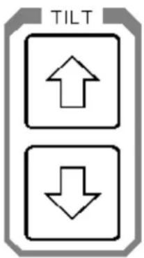
The Tilt Up and Tilt Down arrow buttons control the tilt angle of the transducer for a selected sonar.
- Positive tilt from 0 degrees to +10 degrees (upward)
- Negative tilt from 0 degrees to -90 degrees (downward)
- You also can control the sonar transducer tilt angle by using the roller ball to move the mouse cursor over the display window control panel tilt angle and click on the Up or Down arrow pointer to increase or decrease the tilt
See Part 4 for Pop-Up Control Panel description and operation.
3.3.10 Sector Control Buttons

The Sector Control buttons are used to control the direction (Train Heading) and width of the sector to be scanned by the sonar.
3.3.10.1 Move Sector Left Button

Press the Move Sector Left button to re-center the scanning sector (Train Heading) more to the left.
3.3.10.2 Move Sector Right Button

Press the Move Sector Right button to re-center the scanning sector (Train heading) more to the right.
3.3.10.3 Narrow Sector Button

Press the Narrow Sector button to reduce the width of the scanned sector. The minimum sector width is 8 degrees.
3.3.10.4 Widen Sector Button

Press the Widen Sector button to increase the width of the scanned sector.
- The maximum width setting will provide a full 360 degrees horizontal display.
- You also can control the sonar sector width opening by using the roller ball to
move the mouse cursor over the display window control panel sector width and click on the Up or Down arrow pointer to increase or decrease the sector width.
See Part 4 for Pop-Up Control Panel description and operation.
3.3.11 Sector Aiming Mode Buttons

Press the Mode double arrow button to reverse the scan train direction (same as Scan Reverse mode).
Press the Mode four-quadrant button to change the sector train heading by 90 degrees. Press the four-quadrant button a second time to change the sector train heading by another 90 degrees.
For example: If your center of sector train heading is at 0 degrees, it will change to 90 degrees, next to 180 degrees and then to 270 degrees. The next time you press the quadrant button it will return to 180 degrees and next to 90 degrees and back to 0 degrees.
Note: This feature allows quick adjustment of the sector heading.
3.3.12 Utilities Buttons

3.3.12.1 Off Center Button

Press the Off Center button to move the Own vessel's center of origin.
- Press the Off Center button, a red marker will be displayed on the screen
- Move the mouse red marker cursor to the position that you want to extend the view and left click the mouse button; the range will be doubled in that direction
- Press the Off Center button a second time to return the Own vessel center of origin back to its original position.
3.3.12.2 Zoom Button

Press the Zoom Button to magnify an area of the display around the mouse cursor. Press again to change the magnification. The Zoom button will select X1, X2, and X4 magnification.
3.3.12.3 Stabilize Button

Press the Stabilize (STAB) Button to turn ON automatic transducer pitch and roll stabilization. Press the STAB button a second time to turn stabilization OFF.
3.3.12.4 Speaker Button

Press the Speaker Mute button to activate or deactivate the audio monitor of fish and/or bottom detection. This option is used as an audio alert to inform the operator that detection has been made.
3.3.13 Target Track and Lock Buttons

flowchart
graph TD
    A["TARGET"] --> B["TRACK"]
    A --> C["LOCK"]
Press the Target Track button to activate the tracking of the selected target. To track a target, place the mouse cursor over the desired location and press the Target Track button. A circle will appear on the display and its position will be automatically tracked by the system using the strongest fish echo centered in the "window" represented by two lines on the audio line. The window's size may be selected in the track Window menu.
The vector originating from the target's center indicates target course and speed. The length of the vector increases relative to the target's speed. One knot is represented by a small mark on the vector. A course line can also be displayed showing the target's track.
When the Auto Search is activated during the Target Track mode, the tilt angle will automatically follow the strongest fish echo. The upper and lower tilt angle limits can be used to prevent tracking surface or bottom echoes. The target tracking symbols and data are displayed in a different colour.
Note: The Target Track and Lock option are not available at this time on the SL 35 Sonar and will be available in the near future.
3.3.14 Auto and Manual Search Buttons

flowchart
graph TD
    A["AUTO"] --> B["MAN"]
Press the Auto Search button to activate the selected tilt angle upper and lower limits, with the tilt step size that was pre-set by the system operator.
- In Auto Search, the transducer will automatically change tilt angle after each complete scan search is performed. After each scan search the transducer will tilt up or down within the pre-set limits.
- Press the Manual Search button to allow the transducer to be tilted by pressing the Tilt up or Tilt down buttons.
- The search limits can be changed by using the roller ball and moving the mouse cursor on the Sonar Icon located on the Tool Bar and clicking on the "L" left button.
See Part 4 for the Tool Bar Icon and Sonar setting description and operation.
3.3.15 Symbol Buttons

The Symbol Buttons are used to place special symbols on the display.
3.3.15.1 Latitude / Longitude Button

This button allows you to mark the latitude and longitude of a target on the display. Use the roller ball to move the mouse cursor over a specific location on the sonar image then press the LAT/LONG button to display a Lat/Long marker with a window indicating the latitude and longitude of the selected target. Press the LAT/LONG button a second time to remove the marker and window.
3.3.15.2 Event Mark Button

You can place up to four Event marker symbols anywhere on the display screen as follows:
- Use the roller ball to move the mouse cursor to the desired location on the sonar image.
- Press the Event button to automatically display an event marker 1. If you move the cursor and press the Event button a second time, you can display a second Event marker 2.
- To delete an existing event marker, use the roller ball to move the mouse cursor over it and press the Event button again.
3.3.15.3 Cursor Buttons
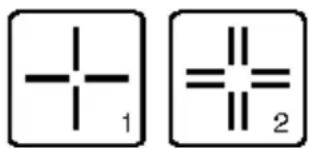
Two special reference cursors are available to be placed anywhere on the sonar image. The positions of these cursors and the range and bearing between them are shown in a Cursor Gauge window.
To place Cursor 1 on the display:
- Use the roller ball to move the mouse cursor to the desired location on the image
- Press the Cursor 1 button to automatically display the Cursor Gauge Window and the Cursor 1 marker.
Use the same procedure with the Cursor 2 button to place the Cursor 2 marker.
To move Cursor 1 to a new position:
- Use the roller ball to move the mouse cursor over the Cursor 1 marker
- Press and hold down the Left "L" button and drag the cursor to a new position
Use the same procedure with the Cursor 2 button to move the Cursor 2 marker.
To delete a cursor:
- Move the mouse cursor over the Wiper icon located on the Tool Bar and click the Left "L" button
- Then move the Wiper over the cursor to be deleted and click the Left "L" mouse button
To hide the Cursor Gauge Window:
- Move the mouse cursor over the X in the upper right hand corner and click the Left "L" button
3.3.16 User Buttons
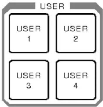
The User Buttons selection can be performed using the menu or the main control panel, which contains four operator selectable set-ups.
Frequently used tasks specific to a particular phase of the fishing operation can be pre-set in the User 1, 2, 3 or 4.
For example “User 1” may be used for the search phase, “User 2” for the evaluation phase, “User 3” for the catch phase and “User 4” for the Dual operation.
3.3.17 Display Mode Buttons
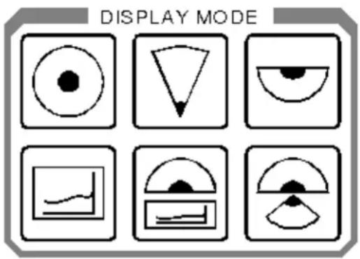
The Display Mode Buttons are used to set the format of the sonar display.
3.3.17.1 Horizontal Display Mode Button

Press the Horizontal Display Mode button to provide a 360 degree plane of coverage for general search.
See Part 5 for Setting Selection.
3.3.17.2 Bow Up Display Mode Button

Press the Bow Up Display Mode button to provide a sector up plane coverage of 180 degrees, with the center of origin at the bottom of the screen. You can change the scanned sector width by using the Sector Width button.
See Part 5 for Setting Selection.
3.3.17.3 Vertical Fan Mode Button

Press the Vertical Fan Display Mode button to provide a vertical section of the underwater bottom conditions on the entire screen. The maximum coverage is 180 degrees. You can change the scanned sector width and heading by using the Sector Width and Heading buttons.
See Part 5 for Setting Selection.
3.3.17.4 Sounder Mode Button

Press the Sounder Display Mode button to provide a fixed echo beam displaying fish echoes below and/or around the vessel.
See Part 5 for Setting Selection.
3.3.17.5 Horizontal Mode with History Mode button

Press the Horizontal with History Display Mode button to provide a 180 degrees Horizontal Sector main display with the history displayed in a second window. This enables the operator to observe the history of fish movement and distribution equivalent to approximately four full 360 degrees scans. It is also useful for detecting bottom fish and reefs.
Note: The History Window cannot be adjusted.
See Part 5 for Setting Selection.
3.3.17.6 Horizontal Mode with Real Time Vertical Strata Mode Button

Press the Horizontal / Vertical Fan Strata Display Mode button to provide a 180 degree Horizontal Sector main display, with the Real Time Vertical Fan displayed in a second window. This enables the operator to observe the history of fish movement and distribution in real time. The Vertical Fan Strata Mode also provides in real time the range, depth and heading of the fish echoes.
Note: The Vertical Fan Strata Window cannot be adjusted.
See Part 5 for Setting Selection.
3.3.18 RX and TX Indicator LED

Receiver “RX” and Transmitter “TX” LEDs are provided to indicate that communication is functioning between the Processing Unit and the Transceiver Unit. If the LEDs do not blink, a communication problem has occurred.
3.3.19 Alarm Indicator LED

The Alarm LED provides a visual indication that the processor unit has failed or a communication error has occurred.
3.3.20 Keyboard (KBD) External Plug-in

An external Keyboard (KBD) is provided for software maintenance support.
3.3.21 Panel Light Dimmer Sensor
A Panel Light Dimmer Sensor is provided to automatically increase or decrease brightness of the light and to turn it off completely in daylight.
3.3.22 Menu Description
The SL 30/35 Menu Description and Operation is described in Part 4 of this manual.
DISCLAIMER
This equipment is not certified or approved for navigation and/or safe-navigation practices and is not to be used for navigation purposes under any circumstances.
PART 4
MENU AND SOFTWARE DESCRIPTION
4. MENU AND SOFTWARE DESCRIPTION....4.5
4.1 INTRODUCTIONS....4.5
4.2 ASSUMPTIONS....4.5
4.3 SCOPE OF THIS MANUAL....4.5
4.4 SOFTWARE INSTALLATION....4.6
4.5 HARDWARE SECURITY KEY....4.6
4.6 MAIN CONTROL PANEL 4.7
4.7 THE TOOLBARS....4.8
4.8 SONAR TOOLBAR....4.8
4.9 MARKER TOOLBAR....4.10
4.10THE STATUS BAR 4.10
4.11REFERENCE CURSORS 4.11
4.12KEY SETTINGS PANEL 4.11
4.13HOW TO CONNECT AND SETUP A HEAD (FIRST TIME OPERATION) .4.12
4.14HOW TO USE THE SONAR (SOME RULES OF THUMB)....4.12
4.15HOW TO RESET TO THE FACTORY DEFAULT SETTINGS 4.13
4.16HOW TO USE THE BASIC SONAR CONTROLS....4.13
4.17HOW TO SELECT UNITS OF MEASURE (FEET, YARDS, METERS).....4.14
4.18HOW TO SET OR ESTIMATE THE VELOCITY OF SOUND....4.14
4.19HOW TO INTERPRET THE SONAR IMAGE....4.15
4.19.1 The Color Palette 4.15
4.19.2 Bright Spots....4.15
4.19.3 Dark Spots 4.15
4.19.4 Shadows 4.16
4.19.5 Noise and Interference....4.16
4.19.6 Masking Effects....4.16
4.19.7 Range Scale and Target Size....4.17
4.19.8 Mirroring Effects....4.17
4.20HOW TO GET THE HIGHEST RESOLUTION IMAGE 4.17
4.21HOW TO GET THE FASTEST UPDATE RATE....4.17
4.22HOW TO USE THE MULTIPLE USER FEATURE....4.18
4.22.1 To create a new user name and configuration:....4.18
4.22.2 To select a different user configuration: 4.18
4.23HOW TO RECORD AND PLAYBACK SONAR DATA 4.18
4.23.1 To record sonar data: 4.18
4.23.2 To playback sonar data: 4.19
4.24HOW TO CUSTOMIZE THE HEAD SETTINGS DISPLAY 4.19
4.25HOW TO CREATE A CUSTOM GAUGE WINDOW 4.20
4.26HOW TO SHOW A CLOSED OR HIDDEN GAUGE WINDOW ......4.20
4.27 ABOUT NETWORKING....4.20
4.28STAND ALONE MODE 4.21
4.28.1 Server Mode....4.21
4.28.2 Passive Client Mode....4.21
4.28.3 Active Client Mode....4.21
4.29HOW TO SETUP A NETWORK CONNECTION (WINDOWS NT/2000) ...4.22
4.30HOW TO SETUP THIS SONAR AS THE SERVER....4.23
4.31HOW TO SETUP THIS SONAR AS A PASSIVE CLIENT....4.23
4.32HOW TO SETUP THIS SONAR AS THE ACTIVE CLIENT 4.24
4.33HOW TO SETUP THIS SONAR FOR STAND-ALONE OPERATION......4.24
4.34HOW TO EXPORT DATA TO A FILE 4.24
4.35HOW TO EXPORT DATA TO A SERIAL PORT....4.25
4.36HOW TO SETUP FOR AND DISPLAY GPS DATA 4.26
4.36.1 To setup the system to accept position data from a GPS receiver: .4.26
4.36.2 To setup the system to display position data from a GPS receiver:.4.26
4.37HOW TO SETUP FOR AND DISPLAY COMPASS DATA 4.26
4.38HOW TO SETUP FOR AND DISPLAY OTHER NMEA DATA 4.27
4.39HOW TO SETUP USER DEFINED SENSORS 4.28
4.40THE FILE MENU....4.29
4.41THE VIEW MENU 4.29
4.55ABOUT DIALOG BOX 4.41
4.56ADD USERS AND GROUPS (WINDOWS NT/2000 OR XP)....4.42
4.57CLIENT LIST DIALOG BOX....4.42
4.58CONFIRM EXIT DIALOG BOX 4.43
4.59DISPLAY SETTINGS DIALOG BOX 4.44
4.59.1 Display Settings: Colors 4.44
4.59.1.1 Palette Styles....4.46
4.59.1.2 Primary Overlay Colors buttons. 4.46
4.59.1.3 The Palette Threshold....4.46
4.59.2 Display Settings: Controls 4.46
4.59.2.1 Sector View....4.47
4.59.2.2 Display Gain 4.47
4.59.2.3 Rx Gain Type....4.47
4.59.2.4 Scan marker 4.47
4.59.2.5 Grid control....4.47
4.59.2.6 Timer 4.47
4.59.2.7 Scroll Speed 4.48
4.59.3 Distributed COM Configuration Properties Applications....4.48
4.59.4 Distributed COM Configuration Properties Default Properties ......4.48
4.59.5 Export Data File Selection Dialog Box....4.48
4.59.5.1 Export Dialog Box....4.48
4.59.5.2 Export: Export Selection 4.49
4.59.5.3 Automatic File....4.49
4.59.5.4 Export: Ports Configuration....4.50
4.59.6 Head Settings Dialog Box....4.51
4.59.6.1 Head Settings: Scan....4.52
4.59.6.2 Head Settings: Transmit 4.53
4.59.6.3 Head Settings: Info 4.55
4.59.6.4 Head Settings: TVG....4.57
4.59.7 Machine Name Dialog Box....4.59
4.59.8 Parameters Dialog Box....4.59
4.59.8.1 Parameters: Magnetic Variation....4.60
4.59.8.2 Parameters: Sound Velocity....4.60
4.59.8.3 Parameters: Units of Measure 4.61
4.59.9 SL35 Properties Identity (Windows NT/2000)....4.62
4.59.9.1 SL35 Properties Location (Windows NT/2000) 4.63
4.59.9.2 SL35 Properties Security (Windows NT/2000)......4.64
4.59.10 Playback Data Dialog Box....4.65
4.59.10.1 Read Event Log File Dialog Box....4.66
4.59.10.2 Record Data Dialog Box....4.66
4.59.10.3 Record Dialog Box 4.67
4.59.11 User Configuration Dialog Box 4.68
4.59.11.1 File Types Used by the SL35 System....4.68
4.59.12 Factory Reset Settings....4.69
4.59.13 Gauge Windows: Customize....4.69
4.59.14 Magnifier Window....4.71
4.59.15 Cursors Gauge Window 4.71
4.59.16 Pointer Gauge Window 4.72
4.59.17 Target Position Gauge Window....4.72
4.59.18 Overload Counter....4.72
4.59.19 Playback Progress Display....4.73
4.59.20 Scope Graph Display....4.74
4.59.21 Security Key Warning....4.74
4.59.22 Sensors Configuration Dialog Box....4.75
4.59.22.1 Sensors Sensor Selection 4.75
4.59.22.2 Sensors Ports Configuration....4.77
4.59.22.3 User Defined Sensors 4.77
4.59.22.4 Sensors Data Display Box....4.79
4.59.23 System Configuration Dialog Box....4.79
4.59.24 System Message Log Dialog Box....4.81
4.60AUDIO SET-UP WINDOW 4.81
4.61POST PROCESSING SET-UP WINDOW 4.82
4.62AUDIO AND POST PROCESSING SET-UP PROCEDURE 4.82
4. MENU AND SOFTWARE DESCRIPTION
4.1 INTRODUCTIONS
The SL 30/35 Sonar System uses a PC as the processing and display unit for one or two sonars. The system operates with digital sonar heads. With the use of this system, a real-time image can be displayed on the screen and can also be recorded for later viewing.
In addition to the sonar data, the system can be connected to receive information from an external sensor, such as DGPS.
4.2 ASSUMPTIONS
This manual was written with the assumption that you are already reasonably familiar with Windows operating system. If not, you should spend a couple of hours with the “Introduction to Microsoft Windows”.
4.3 SCOPE OF THIS MANUAL
The Installation section describes the software set-up of the SL 30/35 Sonar System.
The Display section describes the major components found in the sonar display windows.
The How to section describes how to perform many of the most important functions of the system, in step-by-step detail.
The Menu System section describes each of the menus and their commands.
The Dialog Boxes section illustrates and describes all of the dialog boxes used by the system.
The Reference section includes descriptions of file formats.
4.4 SOFTWARE INSTALLATION
The software CD-ROM installation and set-up procedure are described in Part 8 "Attachments and Drawings"
4.5 HARDWARE SECURITY KEY
The SL 30/35 uses a software protection system that requires a hardware security key or “dongle” to be connected to the processing unit printer port to enable full operation of the system. If you are using an HP/PC processing unit, simply plug the security key “dongle” into the printer port and then connect the printer into the security key “dongle”.
Important Note
The SL30/35 HP/PC Processing Unit is a dedicated unit and is not to be used for any other application, except for which it was intended.
4.6 MAIN CONTROL PANEL

Head numbers indicate, as well as select, the active sonar head in multiple head configuration. All other heads are still running in the background, but the active head will have the top most display window and the focus of the control buttons and sliders of the control panel.
The main control panel allows you to set the Gain, Range, Sector Heading, Sector Width, and Scan Speed for each sonar head in the system. A colour coded graphical symbol shows the sector size and heading for the selected head.
Scroll Speed controls the speed with which the sonar image is scrolled across the window. Adjusting the setting of this control has no effect in Polar or Sector display mode.
Tilt Angle control is used to adjust the tilt angle of the transducer.
The main control panel can be Docked, Undocked, Hidden or put into Autohide mode through the View | Control Panel menu.
4.7 THE TOOLBARS
A Toolbar allows you to perform certain operations with a single mouse click instead of the two or more clicks that are normally required for menu commands.
The SL35 includes two separate toolbars:
- Sonar Toolbar containing frequently used controls for the sonar
- Marker Toolbar containing markers for use with the sonar
Notice that as you move the mouse pointer over any of the toolbar buttons, a simple help message will pop up beside the button describing its function, and a more complete description of the tool will be displayed in the Status Bar.
The toolbars can be hidden by un-checking the appropriate toolbar item in the View Menu. This will allow you to use more of the screen for the sonar image.
4.8 SONAR TOOLBAR

Button Action Menu Equivalent

Full Screen View | Full Screen
| High Resolution View | Display | High Resolution | |
| Save Image File | Save Image | |
| Clear Display View | Display | Clear Display | |
| Pause Head Operations | Pause Head | |
| Run Heads Operations | Run Sonar Heads | |
| Stop Heads Operations | Stop Sonar Heads | |
| Playback Data Operations | Playback Data | Begin Playback | |
| Max. Playback Speed Operations | Playback Data | Max Speed | |
| Pause Operations | Playback Data | Pause Playback | |
| Start/End Record Data Operations | Start/End Record | |
| Scan Reverse Operations | Scan Reverse | |
| Control Head Operations | Control Head | |
| Display Settings | View | Display | Display Settings |
| Arrow | Targets | Arrow |
| Reference Cursor 1 | Targets | Reference Cursor 1 |
| Reference Cursor 2 | Targets | Reference Cursor 2 |
| Latitude/Longitude | None |
| Tape Measure | Targets | Tape Measure |
| Wiper | Targets | Wiper |
| Timer Off/On | View | Display | Display Settings | Controls |
| Magnifier | View | Display | Magnifier |
| Polar | Operations | Control Head | Scan |
974-25007001/2.0 SL 30/35 Hull Sonar Operators Manual Page 4.10 Menu and Software Description

4.9 MARKER TOOLBAR

Button Action Menu Equivalent

4.10 THE STATUS BAR
For Help, press F1
The Status Bar appears at the bottom of the display screen and displays various pieces of information according to the position of the mouse cursor in the display:
When a menu is open, the Status Bar will describe the selected menu item.
When you are performing certain operations such as measuring or annotating
targets, (see Targets Menu) the Status Bar will display simple instructions on what to do next to complete the operation.
If more window space is needed, the Status Bar can also be hidden through the View Menu.
4.11 REFERENCE CURSORS

Reference Cursor 1

Reference Cursor 2
The Reference Cursors (available in the Targets Menu) are two cross-hair type markers that can be placed anywhere on the sonar image to mark a point of interest.
The Cursors Gauge Window shows their position, relative to each other, and to the sonar transducer in terms of ranges and bearings. This gives you a general purpose measuring tool that can be used to estimate the size and orientation of sonar targets, or to mark a spot at a given range and bearing from a known target.
4.12 KEY SETTINGS PANEL
The Key Settings panel shows the main sonar settings. This panel remains on screen at all times.
Range: 810 m
Gain: 85 %
Heading: 0°
Tilt: -25°
Scan Speed: 7.2°
You can move this panel anywhere on the screen by clicking on it and dragging it to the desired position.
4.13 HOW TO CONNECT AND SETUP A HEAD (FIRST TIME OPERATION)
The first time you run the SL35 Sonar program, you must configure the system for your hardware as follows:
- Be sure the dongle is connected to a printer port on your computer
- Be sure the sonar head has been connected to a serial port and has power
- Start the SL35 program by double clicking on its icon
- In the Configuration menu, select Connect Heads. The System Configuration dialog box should appear showing every COM port that is available on your computer
- Click on the COM port you want to use for connection to the sonar head. For the example, we will select COM2
- The box COM2 Configuration should appear showing the Port Hardware Address for COM2.(Click here to see example)
- Check the Enable for Head Control box, then reboot the computer
- In a few seconds, the head should be detected, and the System Configuration: Devices page should change to show the Head Name, Part Number and Serial Number
- You can change the name of the sonar head at this point. Just select the head in the tree structure and then click in the Head Name edit box and type the name you want to give that head. Note that this name will be used from this point on to reference the selected head through out the operational life time of the system. The name is persistent and will be used the next time you run the sonar system. It will however, be replaced by a generic name the next time you go through automatic detection of the heads on the telemetry line
- Click the OK button
4.14 HOW TO USE THE SONAR (SOME RULES OF THUMB)
Following are some general guidelines on how to use and adjust the sonar for many applications:
Most of the palettes have a unique 'saturation' color to indicate maximum echo strengths. Any echo with a strength beyond this is shown in the same color. If large parts of the image are being shown in this saturation color, you have
probably set the gain too high. Adjust the gain so that about only about 5% of the total image is shown in the saturation color
If you are trying to track a moving target, or track a target from a moving vehicle, use the scan reverse button (or Scan Reverse in the Operations Menu) to improve the update rate on the target
- Limit the Sector Width to the area of interest to maximize the update rate. (See Control Panel)
Use a higher Scan Speed when highest update rate is important. (See Control Panel)
Use the slowest Scan Speed when you are trying to discern a small target or require maximum detail in the image
- Set the Range to the shortest setting that allows you to see what you need to see. This will give you the highest update rate and the best image quality. (See Control Panel)
- Always keep in mind the overall geometry of the situation, including the fact that the sonar beam is fan shaped and becomes very narrow the closer you are to the transducer. As you move closer and closer to a target, it is quite possible for it to disappear simply because it has moved over or under the beam
4.15 HOW TO RESET TO THE FACTORY DEFAULT SETTINGS
To reset all sonar settings to their factory default values:
- Select Factory Reset in the Operations menu
- Select Yes when you are asked if you want to proceed
4.16 HOW TO USE THE BASIC SONAR CONTROLS
To use the basic sonar controls:
- Click on the

Run button to start the sonar scanning
- The other basic sonar controls are all found in the Control Panel. To make the control panel visible, select Control Panel in the View menu and click on Docked or Floating
- Adjust the Range control to the setting you need
- Adjust the Sector Heading and Width controls so the sonar will scan the area you want to cover
- Adjust the Scan Speed as desired. This will trade off image quality against update rate
- Adjust the Gain control; a good starting point is 50 percent
4.17 HOW TO SELECT UNITS OF MEASURE (FEET, YARDS, METERS)
To select the units of measure for the sonar:
- In the Configuration Menu, select Parameters to open the Parameters | Units of Measure dialog box
- Click a radio button in the Distance group to select the distance units you want to use
- Click a radio button in the Temperature group to select the temperature units you want to use
- Click the OK button
4.18 HOW TO SET OR ESTIMATE THE VELOCITY OF SOUND
For maximum accuracy it is important that you set the sound velocity value to match local conditions.
If you have a known or measured value for the local sound velocity, enter it as follows:
• In the Configuration Menu, select Parameters
- Click on the Sound Velocity tab to open the Parameters | Sound Velocity dialog box
- Enter the known value in the Value to be Used box. Caution: Be sure the units of measure are the same for the known value and the sonar, i.e. both in meters per second or both in feet per second
- Click the OK button
To calculate a sound velocity based on temperature and salinity estimates or measurements:
• In the Configuration Menu, select Parameters
- Click on the Sound Velocity tab to open the Parameters | Sound Velocity dialog box
- In the Calculate from Temperature, Salinity, Depth box, enter estimates of water Temperature, Salinity and Depth of the sonar head.
Note: Salinity of pure fresh water is near 0 ppm, salinity of sea water is typically between 30 and 40 ppm. Brackish or mixed fresh and salt water will be somewhere in between.
- Click the Calculate button. The calculated value will be entered automatically in the Value to be Used box
- Click the OK button
4.19 HOW TO INTERPRET THE SONAR IMAGE
4.19.1 The Color Palette
The sonar image is a map of the echo returns over the scanned area. A sequence of colors is used to show the relative strengths of the returns. Several colour schemes or image palettes are available. Most of them use darker colors to indicate weak returns and brighter, lighter colors to indicate the stronger returns.
4.19.2 Bright Spots
Bright spots in the image indicate strong sonar targets. Generally, this indicates a hard, highly reflective surface.
4.19.3 Dark Spots
Dark spots in the image indicate either areas of low reflectivity (soft areas) or possibly an acoustic shadow zone behind a target.
4.19.4 Shadows
Most targets will block the transmission of sound either by reflecting it or absorbing it. This will leave a shadowed area beyond the target that is not ensonified and therefore will not generate any echoes. This is very similar to the shadow formed when an object is illuminated with a single light source. The shadow behind a target can often yield more information about the target than the reflections from the target itself. The shadow will often reveal the shape of the target, but you must remember that the shape will usually be distorted according to the position of the sonar head relative to the target and the bottom, and according to the slope of the bottom. It is often possible to estimate the height of a bottom target based on the length of the shadow and the known height of the sonar ahead.
4.19.5 Noise and Interference
It is usually easy to recognize interference from other acoustic sources such as echo sounders, pingers or other sonars. These sources all produce pulses at regularly timed intervals and will therefore tend to create a regular or symmetrical pattern of 'blips' on the screen. Electrical interference usually occurs at a much higher periodic rate, and will tend to appear as spiral patterns on the screen. Mechanical noise sources such as propellers, hydraulic pumps, and thrusters, are usually more directional and tend to show up only when the sonar head is pointing directly towards them.
4.19.6 Masking Effects
Sonar signals are easily blocked by air or gas bubbles in the water or on the transducer face. As an example, the aeration present in the wake of a vessel will often last for ten to twenty minutes and effectively mask out any sonar returns on the far side. The aeration blocks the outgoing pulses as well as any returns. Another source of gas or air bubbles can be found when a sea bottom containing decomposing organic matter is disturbed by dredging or plowing.
4.19.7 Range Scale and Target Size
When looking at any sonar image you must keep in mind the range scale you are using, the position of the sonar relative to the target you are looking for, and the size of the target. For example, a target the size of a beer can will be very small and probably not visible on a one hundred meter range scale.
4.19.8 Mirroring Effects
If you try using the sonar inside a rectangular tank such as a swimming pool, it is quite likely that you will see phantom targets outside the tank boundary. This occurs because the tank walls are hard and smooth and can reflect the sound pulse from one wall to another and finally back to the sonar transducer. The sound path is similar to the path of a billiard ball making multiple bounces off the sides and ends of the table. Although it is not very common, there are occasions when this same effect will happen in the sea, particularly when near certain large man made structures. If you see something in the image that doesn't make sense, look at the geometry or arrangement of the targets and see if a multiple path reflection could explain the mis-plotted targets.
4.20 HOW TO GET THE HIGHEST RESOLUTION IMAGE
To get the highest possible image quality:
- Arrange for the sonar head to be absolutely stable in a fixed location
- Select the slowest possible scan speed
- If possible, adjust the computer display resolution to 1280 x 1024 and select the High Resolution mode
- Adjust the Pulse Length
4.21 HOW TO GET THE FASTEST UPDATE RATE
To get the fastest update rate on a particular area:
- Select a higher scan speed
- Adjust the Sector Heading and Width to limit the area of coverage to the minimum required
- Use the shortest range setting that gives the required coverage
- Select the Low Resolution mode
• Use the Scan Reverse control 📋 to repaint a target as quickly as possible
4.22 HOW TO USE THE MULTIPLE USER FEATURE
The SL35 allows you to save the system settings under different user names. This allows multiple users to save and quickly recover their preferred settings.
4.22.1 To create a new user name and configuration:
- Select Users in the Configuration menu then select Define
- Click the Add button in the Users Configuration dialog box
• Edit the name in the User Information Name edit box - Click the OK button; the newly added user name will become the current or active user
4.22.2 To select a different user configuration:
- Select Users in the Configuration menu then select the desired user name.
4.23 HOW TO RECORD AND PLAYBACK SONAR DATA
4.23.1 To record sonar data:
- Click the Record button in the Sonar Toolbar
- Operate the sonar as normal
- Press the Stop button to end recording
4.23.2 To playback sonar data:
- Click the Playback button in the Sonar Toolbar
- Select the name of the file you want to playback. Only files of type SMB can be selected
- To speed up the playback press the 📋 Maximum Playback Speed button
- To pause or resume playback press the Pause button
- To stop playback before the file is finished, press the Stop button
4.24 HOW TO CUSTOMIZE THE HEAD SETTINGS DISPLAY
The Head Settings display window is a pre-defined gauge window that cannot be modified. To make a customized version of this box, you must make a duplicate and then modify it.
To make a customized head settings display window:
- Right click anywhere in the sonar window to open the popup menu
- Select Other Settings and Customize to open the Gauge Windows dialog box
- Click on the Head Settings icon in the Gauge Windows box then click the Duplicate button
- Enter a name for the new customized head settings display and press OK
- Select the parameters you want to display in the new gauge window by selecting them from the Unused Parameters list then pressing the Add button
- Remove unwanted parameters by selecting them by Label in the Used Parameters list then pressing the Remove button
- Click the Close button; the new gauge window will appear in the upper left corner of the sonar window and can be dragged to any desired position
4.25 HOW TO CREATE A CUSTOM GAUGE WINDOW
To create a custom gauge window:
- Right click anywhere in the sonar window to open the popup menu
- Select Other Settings and Customize to open the Gauge Windows dialog box
- Click the New button to open the Entry dialog box
- Enter a name for the new gauge window then click OK
- Select the parameters you want to display in the new gauge window by selecting them from the Unused Parameters list then pressing the Add button
- Remove unwanted parameters by selecting them by Label in the Used Parameters list then pressing the Remove button
- Click the Close button; the new gauge window will appear in the upper left corner of the sonar window and can be dragged to any desired position.
4.26 HOW TO SHOW A CLOSED OR HIDDEN GAUGE WINDOW
To show a gauge window that has been closed or hidden:
- Right click anywhere in the sonar window to open the popup menu
- Select Other Settings and Customize to open the Gauge Windows dialog box
- Click on the icon of the gauge window you want to make visible in the Gauge Windows box
- Click the Show button
- Click the Close button; the gauge window should now appear at its previous position
4.27 ABOUT NETWORKING
You must have already setup the DCOM for the appropriate operating system on your computer. To setup networking on your computer, please refer to "How to Setup a Network Connection (Windows XP)".
Sonar networking is only possible if the computers are physically connected together and can be seen through the Network Neighborhood. Users can use Local Area Networks (LAN) or Peer To Peer networking for this purpose. Dial in networking is limited to one of the machines being an NT-Server.
In the context of sonar operation, The SL30/35 can be in stand alone, server, passive and active client mode.
4.28 STAND ALONE MODE
The default operating mode of the SL30/35. In this mode, it can operate sonar heads or playback recorded data.
4.28.1 Server Mode
For systems that are equipped with sonar heads. SL30/35 switches to server mode when connecting to a remote client. It passes all its operational settings as well as sonar data to the client. There can be only one server machine in a network.
4.28.2 Passive Client Mode
For viewing sonar data generated by a remote machine in server mode. Passive clients can not be operating sonar heads locally. The passive mode prevents the user from controlling the remote sonar heads. Display settings such as palette, window size, position etc. can be changed locally. There can be multiple client machines attached to a single server.
4.28.3 Active Client Mode
For both viewing sonar data and actively control the sonar heads connected to the remote server. Active clients can not be operating sonar heads locally. System settings and operations such as Run, Stop, Record, Playback, Connect Heads, etc. of the remote server can not be changed and controlled from the client. Only the head settings can be changed from an active client. These would include Gain, Range, Step Size, TVG, etc. There can be multiple client machines attached to a single server but only one active client in the network. Passing of control from one client to another is negotiated interactively.
System performance and throughput depends on the speed of the communication link between the computers. Generally, LAN and Peer To Peer networking run at 10 Mbits speed which should be enough to pass sonar data from server to client in an
uninterrupted form. Dial in networking can run at 28 and up to 56 Kbits which is much slower than the rate at which sonar data is generated. The system throughput is compromised under this circumstance.
Users can operate the SL30/35 in networking mode through the Network Menu.
4.29 HOW TO SETUP A NETWORK CONNECTION (WINDOWS NT/2000)
Important Note:
If you choose to select a different directory name than the default naming for the SL30/35 installation, then the directory names should not have any white characters (space) in them. DCOM can not deal with these names. If this is the case, then uninstall the SL30/35 and reinstall it with proper naming mechanism.
To setup a network connection:
- Push the Start button on your task bar (normally located at the bottom of the screen) and select Run... from the popup menu
- Type in "dcomcnfg" and press OK to open the Distribute Com Configuration Properties dialog box
- Click on the Default Properties tab to open the Distributed COM Configuration Properties Default Properties page. Check Enable Distributed COM on this computer, set the Default Authentication Level to Connect, and set the Default Impersonation Level to Identify
- Click the Applications tab to open the Distributed COM Configuration Properties Applications page and select SL30/35 from the list of installed applications
- Click the Properties button to open the SL30/35 Properties dialog box. Click on the Location tab to open the SL35 Properties Location page. Check the Run application on this computer checkbox
- Click the Security tab to open the SL35 Properties Security page. Select Use custom access permissions, Use custom launch permissions and Use custom configuration permissions
- Press the Edit button to open the Registry Value Permissions dialog box. If the text Everyone appears in the Name list, go to step 10, otherwise continue with step 8
- Press the Add button to open the Add Users and Groups dialog box
- Select Everyone in the Names list and press the Add button. Press OK to
accept the selection. You should now see Everyone in the Registry Value Permissions dialog box. Press OK to return to the SL30/35 Properties Security page
- Repeat from step 7 for each of the three permission groups (access, launch, and configuration) on the Security page
- Click the Identity tab to open the SL30/35 Properties Identity page and select The interactive user option
- Press OK to accept the changes and close the dialog box. You should now be back at the Distributed COM Configuration Properties dialog box. Press OK to accept and close this dialog box
- Reboot the computer to make the changes take effect
4.30 HOW TO SETUP THIS SONAR AS THE SERVER
To setup this sonar as the server:
- In the Network menu, select Connect to Client to open the Machine Name dialog box
- Select the client you want to connect to in the Remote Machine Name combo box
- Click the OK button
Note 1: The system must be enabled for a network connection before using this feature. See how to Setup a Network Connection (Windows XP).
Note 2: The server is the sonar that has the active sonar heads.
4.31 HOW TO SETUP THIS SONAR AS A PASSIVE CLIENT
To setup this sonar as a passive client:
- In the Network menu, select Connect to Server to open the Machine Name dialog box
- Select the server machine you want to connect to in the Remote Machine Name combo box
- Click the OK button
Note 1: The system must be enabled for a network connection before using this feature. See How to Setup a Network Connection (Windows XP).
Note 2: A passive client can only view data from a server.
4.32 HOW TO SETUP THIS SONAR AS THE ACTIVE CLIENT
To setup this sonar as the active client:
- In the Network menu, select Connect to Server to open the Machine Name dialog box
- Select the server machine you want to connect to in the Remote Machine Name combo box
- Click the OK button; at this point, this machine is now a passive client
• In the Network menu, select Request Control
Note 1: The system must be enabled for a network connection before using this feature. See How to Setup a Network Connection (Windows XP).
Note 2: The active client can control and view data from a server.
By default, the sonar will be in stand-alone mode unless it has been configured to act as a network client or server.
To restore this sonar to stand-alone mode: If the sonar is currently configured as a client:
- In the Network menu, select Disconnect from Server
If the sonar is currently configured as a server:
- In the Network menu, select Disconnect from Client to open the Client List dialog box
- Select all of the clients then click OK
4.34 HOW TO EXPORT DATA TO A FILE
The data export feature allows you to export profile data from a sonar head, or export all data received on a COM port connected to a sensor.
To export data to a file:
- Select Export Data in the Operations menu.to open the Export Selection page
- Check the Enable checkbox in the File group
- Check the Automatic File Naming checkbox if you want the files to be name automatically; otherwise, click the Select File button and enter or select a filename
- In the Select Sources list, select an icon representing a source you want to record then check the Select Sensor checkbox
Note: If you want to export profile data from a head you must select a sonar head. If you want to export data from a sensor you must select the COM port the sensor is connected to. Individual sensor types cannot be selected as sources.
- Repeat step 4 as required to select all of the sources you want to record
- Click the OK button; data from the selected sources will be written to the selected file as it is received from the sensors
4.35 HOW TO EXPORT DATA TO A SERIAL PORT
The data export feature allows you to export profile data from a sonar head, or export all data received on a COM port connected to a sensor.
To export data to a serial port:
- Select Export Data in the Operations menu.to open the Export Selection page
- Check the Enable checkbox in the Port group
- Select the COM port you want to use for output
- In the Select Sources list, select an icon representing a source you want to output then check the Select Sensor checkbox
Note: If you want to export profile data from a head you must select a sonar head. If you want to export data from a sensor you must select the COM port the sensor is connected to. Individual sensor types cannot be selected as sources.
- Repeat step 4 as required to select all of the sources you want to output
- Click the Apply button
-
Click the Ports Configuration tab to open the Export Ports Configuration page
-
Select the COM port you want to use and set the Communications Settings as required
- Click the OK button; data from the selected sources will be written to the selected port
4.36 HOW TO SETUP FOR AND DISPLAY GPS DATA
4.36.1 To setup the system to accept position data from a GPS receiver:
- Select Sensors in the Configuration Menu to open the Sensors Configuration Sensors Selection page
- Select the communication (COM) port you want to use for the GPS by clicking on the desired COM port icon
- Select GGA in the Standard list then click the Connect button below this list. An icon for the GGA sentence will appear under the selected COM port icon. Note: You can also use GGL, RMA, or RMC if your GPS does not support the GGA sentence
- Click the Ports Configuration tab to open the Sensors Ports Configuration page
- Click on the COM port icon that you are using for the GPS
- Click the Use NMEA Settings button. Note: This will set the Bits Per Second (Baud rate) to 4800. If your GPS receiver uses a different rate, set the Bits Per Second accordingly
- Click the OK button
4.36.2 To setup the system to display position data from a GPS receiver:
- Configure the system to accept GPS data as above.
• In the View menu, select Sensors.
4.37 HOW TO SETUP FOR AND DISPLAY COMPASS DATA
To setup the system to accept heading data from a compass:
- To enter magnetic variation, select Parameters in the Configuration menu to open the Parameters dialog box
- Click on the Magnetic Variation tab to open the Parameters Magnetic Variation page
- Enter the local magnetic variation. This information is available on marine charts of the area. Click the OK button
- To setup the system to display heading data from a compass:
- Configure the system to accept compass data as above
• In the View menu, select Sensors - Select Sensors in the Configuration Menu to open the Sensors Configuration Sensors Selection page
- Select HDG in the Standard list then click the Connect button below this list. An icon for the HDG sentence will appear under the selected COM port icon. Note: You can also use HDT or HDM if your compass does not support the HDG sentence
- Click the Ports Configuration tab to open the Sensors Ports Configuration page
- Click on the COM port icon that you are using for the compass
- Click the Use NMEA Settings button. Note: This will set the Bits Per Second (Baud rate) to 4800. If your compass uses a different rate, set the Bits Per Second accordingly
- Click the OK button
If you are using a magnetic or fluxgate compass (not a true gyro compass) you should enter the local magnetic variation in the following steps:
- Select the communication (COM) port you want to use for the compass by clicking on the desired COM port icon
4.38 HOW TO SETUP FOR AND DISPLAY OTHER NMEA DATA
To setup the system to accept data from an NMEA device:
- Select Sensors in the Configuration Menu to open the Sensors Configuration Sensors Selection page
- Select the communication (COM) port you want to use for the NMEA device by clicking on the desired COM port icon
-
Select a sentence in the Standard list that is supported by your NMEA device, then click the Connect button below this list. An icon for this sentence will appear under the selected COM port icon
-
Add additional sentences by repeating step 3 as required
- Click the Ports Configuration tab to open the Sensors Ports Configuration page
- Click on the COM port icon that you are using for the NMEA device
- Click the Use NMEA Settings button
Note: This will set the Bits Per Second (Baud rate) to 4800. If your device uses a different rate, set the Bits Per Second accordingly.
- Click the OK button
To setup the system to display data from an NMEA device:
- Configure the system to accept NMEA data as above
• In the View menu, select Sensors
4.39 HOW TO SETUP USER DEFINED SENSORS
To setup the system to accept data from a user defined sensor:
- Select Sensors in the Configuration Menu to open the Sensors Configuration Sensors Selection page
- Click on the User Defined Sensors tab
- Create a user defined sensor by following the rules outlined for the User Defined Sensors page. Click the Apply button when you are done
- Click on the Sensors Selection tab to open the Sensors Selection page
- Select the communication (COM) port you want to use for the user defined sensor by clicking on the desired COM port icon
- Select the sensor name from the User Defined list, then click the Connect button below this list. An icon for this sensor will appear under the selected COM port icon
- Click the Ports Configuration tab to open the Sensors Ports Configuration page
- Click on the COM port icon that you are using for this sensor
- Set the Communications Settings to match those of the user defined sensor
- Click the OK button
To setup the system to display data from a user defined sensor:
- Configure the system to accept user defined data as above
• In the View menu, select Sensors
4.40 THE FILE MENU
The File Menu contains the following items:

Save Image is used to save the image in the active window as a bitmap file.
Save Without Overlay will also save the image but without any grid lines or other overlay markings.
Exit is used to exit the PC Sonar program; the Confirm Exit dialog box will ask you to confirm that you want to exit
4.41 THE VIEW MENU
The View Menu contains the following items:

Control Panel opens the Control Panel Menu.
Display opens the Display Menu.
Message Log opens the Message Log Menu
NMEA Data opens the Sensors Data display box.
Playback progress shows or hides the Playback Progress status box.
Events Log File opens the Open Event Log File dialog box.
Sonar Toolbar shows or hides the Sonar Toolbar.
Marker Toolbar shows or hides the Marker Toolbar.
Status Bar hides or shows the Status Bar
Full Screen allows the sonar image to use the entire display area.
Screen Fit Image allows the sonar image to be enlarged or shrunk to the current dimensions of the display window. This feature requires considerable computing time and may compromise system performance. Under this mode, ZOOM and Magnifier windows are disabled. This mode is not available when the High resolution display is enabled.
4.42 CONTROL PANEL MENU
View | Control Panel opens a sub menu with the following items:
- Docked Floating Hidden Autohidden
Docked Check this if you want the Control Panel to be fixed at the right edge of the display.
Floating Check this for a movable control panel.
Hidden Check this to hide the control panel. This will provide more space for sonar windows.
Autohidden will hide the control panel at the right edge of the display, exposing it only when the mouse is moved over it.
4.43 DISPLAY MENU
View | Display opens a sub menu with the following items:
| Pointers |
| Reference Cursors |
| Head Settings |
| Magnifier |
| High Resolution |
| Display Settings |
| Clear Display |
| Customize |
Pointers opens the Pointer Gauge Window
Reference Cursors opens the Cursors Gauge Window
Head Settings opens the Head Settings Gauge Window
Magnifier opens the Magnifier Window
High Resolution sets the sonar to use a high resolution 1280 by 1024 display.
Display Settings opens the Display Settings dialog box.
Clear Display clears the active sonar image.
Customize opens the dialog box to setup the entries in a gauge window (see Gauge window customize).
4.44 MESSAGE LOG MENU
Message Log opens a sub menu with the following items:
| ✓ ActiveVisible |
| Clear |
Visible opens the System Message Log dialog box.
Active enables or disables logging of messages in the system Message Log.
Clear clears the contents of the Message Log.
The Configuration Menu contains items you will need to setup and configure the sonar for your application:

Connect Heads opens the System Configuration Dialog Box. Its use is explained in How to Connect and Setup a Head (First Time Operation).
NMEA Setup opens the Sensors Configuration Dialog Box.
Parameters opens the Parameters Dialog Box.
Users opens the Users Menu.
Save Settings allows the user to instantly save all operational settings of the system under the current user. It is advisable to save the settings after you have setup the system as desired, so that a copy of the settings is immediately saved in the registry and available the next time you run the system. Windows is known to crash from time to time, and in such cases, settings will be lost unless they have been saved. This menu also provides the user with the option to save the settings in a file that can be stored on local hard drive or a floppy for backup. The system asks if the file storage is desired by the user and provides the mechanism to do it. Note that the file is saved under the current user name.
Load Settings allows the user to load the operational settings of the system from a file that had been saved before. The name of the file is used as a representation of the user name. If the name was already in the system, then the settings are transferred to that user in the registry. Otherwise, a new user is created in the registry and activated as the current user of the system.
4.46 USERS MENU

Generic allows you to select a pre-defined user configuration.
Define allows you to define and name a new configuration through the User Configuration Dialog Box.
4.47 THE OPERATIONS MENU
The Operations Menu contains commands required for everyday operation of the sonar:

Run Sonar Heads causes the detected heads to start operating.
Note: You will see the Security Key Warning if dongle is not connected.
Stop Sonar Heads causes the detected heads to stop operating.
Select Head... selects one of the detected sonar heads on the telemetry to be the active head and brings its image to the foreground. Note that the other sonar heads would still be operating in the background.
Control Head opens the Head Settings Dialog Box.
Pause Head causes the selected head to stop scanning.
Scan Reverse reverses the scan direction of the selected head.
Record Data opens the Record Dialog Box.
Pause Record pauses the recording of the sonar data.
End Record ends recording.
Export... opens the Export Dialog Box allowing you to export data.
Pause Export pauses the exporting of data on a serial port.
End Export ends the exporting of data on a serial port.
Playback Data opens the Playback Data Menu.
Factory Reset... resets the heads operational settings to the Factory Reset Settings.
4.48 PLAYBACK DATA MENU
Begin Playback... Pause Playback Max Speed End Playback
The Playback Data menu offers the following choices:
Begin Playback opens the Playback Data Dialog Box that allows you to select a file for playback.
Pause Playback pauses playback leaving a stationary image.
Max Speed plays back data at maximum speed if checked.
End Playback ends data playback.
4.49 THE TARGETS MENU
The Targets Menu contains entries that enable several target measurement tools:

Arrow The default mouse pointer. This tool must be selected to allow the use of the Pop-Up menu in a sonar window (via the right mouse button). The arrow tool can be used to move overlays on the sonar display by dragging them with the left mouse button. Overlays can be re-sized by dragging their edges, and some can be edited by double-clicking on them.
Reference Cursor 1 Used to position Reference Cursor 1. Shows the Cursors Gauge Window, if previously hidden. Place the cross-hair on the target and press the left mouse button. Once placed, the cursor overlay can be dragged with the Arrow Tool.
Reference Cursor 2 Identical to the Reference Cursor 1 Tool, except that it refers to the secondary reference cursor.
Tape Measure Used to measure the length of a target. Simply click the left mouse button at the beginning of the target, keeping the left mouse button down, drag the mouse to the end of the target. The length and bearing of the target is displayed dynamically.
If a persistent measurement is desired, perform the above operation with the right mouse button. After the measurement is complete, drag the measurement overlay away to any position on the screen which is easily legible.
Height Measure This is a 3 step measurement. When this tool is selected, a line extends from the image origin. First, place the mouse cursor on the far side of the target's shadow and click the left mouse button. Next, move the cursor to the far side of the
target itself and click the left mouse button again. Finally, move the cursor to the position of the first bottom return and click the left button again. A measurement overlay is placed on the sonar display indicating the height of the measured object.
String Measure This tool is used for area and perimeter measurement of the target. Simply select the String Measure Tool from the tool bar or the menu, use the left mouse button and click around the outer edge of the target. When finished (reaching the starting point) double click the left mouse button for calculations to start. A measurement overlay is then placed on the display and you must click once when you are satisfied with its location. Area and perimeter information will be displayed in the current units.
Text Used for annotation. Drag from any point on the screen to label that point with a text box overlay. To enter new text or change the existing text, simply double click on the text box.
Wiper Used to delete existing measurement overlays explained above. Just left click on each item you wish to delete.
4.50 NETWORK MENU
You must have already setup the DCOM for the appropriate operating system on your computer. To setup networking on your computer, please refer to "How to Setup a Network Connection (Windows NT/2000)".

Connect To Server Is used to connect to a remote server machine. The server machine is the computer with sonar heads attached to it. This would make the local machine
a Passive Client, where sonar data can be viewed but not controlled. Upon requesting to connect, the system asks for the name of the machines through the Machine Name Dialog Box.
Disconnect From Server disconnects from the server machine.
Connect To Client is used to connect to a remote client machine. A client machine is the computer with no sonar heads attached to it. This would make the local machine a Server, usually with sonar heads attached and operating. Upon requesting to connect, the system asks for the name of the machines through the Machine Name Selection Dialog box. The remote client is in passive mode by default and can only observe the sonar data.
Disconnect From Client disconnects from a specific client machine. There can be multiple clients attached to a server machine. The system prompts the user with the Client List dialog box to select a particular machine.
Beep Remote This is a diagnostic procedure to sound a beep on the remote computer. You must make sure that the sound is enabled on the remote machine. If the connection is made but you can not hear a beep on the remote machine, then there is a problem with the connection and the connection should be broken and attempted again.
Display Network Connections This menu can be used to display the list of all connections to this machine. It also indicates if the local machine is a server or client.
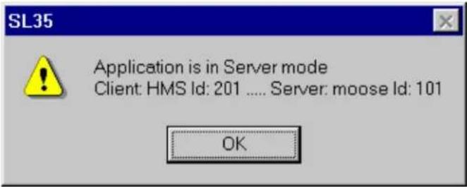
Request Control. This menu can be used by a passive client to gain control privileges from the server and become an active client. Note that you must have a dongle attached to the printer port, otherwise the system will prompt you with "Key not connected" message. If there is an other active client in the network, then the system pops a dialog box in the active client asking permission to take control away.
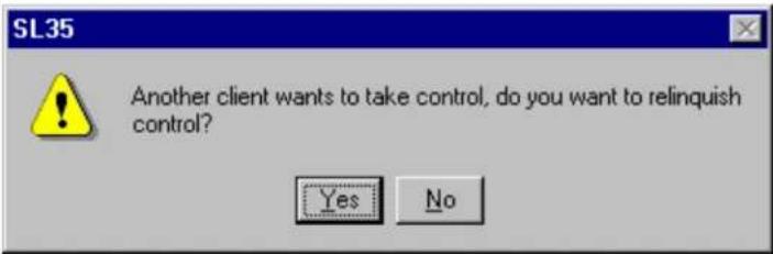
If the active client agrees to relinquish control by selecting "Yes", then the requesting machine becomes the active controller. Both clients are informed of the change in the active client.


Relinquish Control An active client may become passive through the use of this menu.
Remove Control Privilege From Clients The server machine may forcefully take control privilege away from an active client through the use of this menu at any time.
4.51 THE WINDOW MENU
The Window Menu contains commands for selecting and arranging the active windows:
| Next | Ctrl+F6 |
| Previous | Ctrl+Shift+F6 |
| Cascade | |
| Tile Horizontally | |
| Tile Vertically | |
| Arrange Icons | |
| √ 1 Disconnected 1 | |
Next selects the next window.
Previous selects the previous window.
Cascade arranges all of the open windows in a cascaded pattern.
Tile Horizontally arranges all of the open windows as horizontal tiles.
Tile Vertically arranges all of the open windows as vertical tiles.
Arrange Icons allows you to arrange all icons.
4.52 THE HELP MENU
The Help menu contains system information related items:
| Help Topics |
| About... |
Help Topics opens the PcSonar On-line Help System,
About... opens the About dialog box that identifies the PcSonar software version.
4.53 POPUP MENUS
When you click the right mouse button in a sonar image window, a popup menu will appear as below:

(Note: The Arrow Tool in the Targets Menu must be selected or the menu will fail to appear.)
Select Pointer to open the Pointer Display Box.
Select Cursors to show the Cursor display box.
Select Head Settings to show the Head Settings Gauge Window. This is particularly useful during playback mode to see the operational settings of the recorded head.
Select Display Settings to open the Display Settings dialog box associated with this view to change colors.
Select Control Head to open the Head Settings Dialog Box.
Select Clear Display to clear the sonar image from the screen.
Customize opens the dialog box to setup the entries in a gauge window (see Gauge Window: Customize). This is particularly useful in playback to inspect the desired operational settings. The user can choose to display any one of the available settings as listed in the Gauge window list.
4.54 HEAD SETTINGS GAUGE WINDOW
The Head Settings gauge window shows the settings of some of the main parameters for the sonar head.
This is the SL35 head settings window. It shows some of the the current operational settings of the sonar head associated with this window.
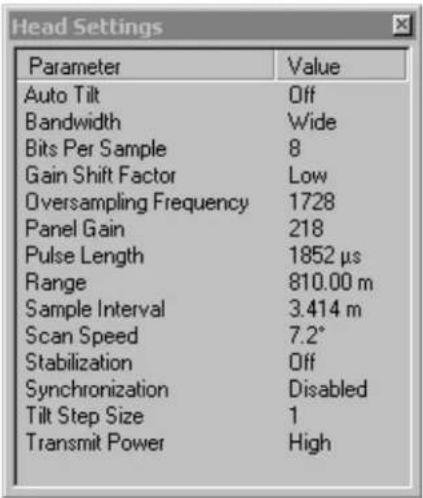
NOTE that the user can setup specific windows with completely user configurable set of parameter list through the customized gauge window.
4.55 ABOUT DIALOG BOX

The version number is the software version of the SL30/35 sonar installed on your computer. If you are using the Window's XP version, then the version number is followed by the operating system.
The serial number is that of the hardware key used in conjunction with the SL30/35.
If the Dongle is programmed to operate a server machine, it will display the "Server option enabled" message.
4.56 ADD USERS AND GROUPS (WINDOWS NT/2000 OR XP)

4.57 CLIENT LIST DIALOG BOX

The Confirm Exit dialog box is intended to prevent quitting the program unintentionally.

If you select "Yes" and there is network connections then the system will ask you to confirm disconnecting from the remote machine.
If there are no network connection or you select "Yes" to disconnect from remote machine, then the system will ask you if you want to save the settings. If you have been experimenting with the operational settings of the system and are not sure if you want to save them permanently, then select No to this prompt.

If you select Yes, you will get another dialog where you can specify to which user you want to save these settings.
4.59 DISPLAY SETTINGS DIALOG BOX
The Display Settings dialog box allows you to set display colors, the image palette, and orientation of the sonar image on the display.
It includes the following pages:
Colors, Controls
4.59.1 Display Settings: Colors
![Display Settings - SL 35 Colors | Controls | Primary Overlay Colors Sector Limit Profile Points Grid Cursor 1 Cursor 2 Annotation Colors on Second Head Sector Limit Profile Points Palette Styles Simrad [1] Palette Threshold ( 0 ) OK Cancel Apply Help](/content/2026/05/868320/images/33681b76cca06451d715dd892b99358b09cd441d2ecab40abbb10de9cc519194.jpg)
4.59.1.1 Palette Styles
Combo box to select the color palette to be used for the sonar image.
4.59.1.2 Primary Overlay Colors buttons.
The primary colors buttons allow you to select the colors for various elements in the display, for each view. When in Fused Head display, these colors are associated with the first head, which is the head whose name appears first on the view title.
The Colors On Second Head buttons are only applicable to fused head display.
4.59.1.3 The Palette Threshold
The palette threshold control allows you to set the minimum level for echo returns to be displayed. With the control set at zero, all signal levels are displayed. As you increase the threshold, weaker signals will be removed from the display.
4.59.2 Display Settings: Controls
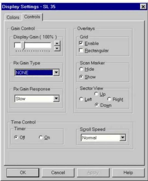
4.59.2.1 Sector View
The sector view allows you to select Up, Down, Left, and Right as the orientation of the sonar image display. Generally, you should choose the view that seems to match the orientation of the sonar head. If you are looking ahead, choose Sector Up. If you are looking down as when profiling, you will probably want to choose Sector Down.
4.59.2.2 Display Gain
The display Gain should normally be set to 100 percent. It should only be used in playback to adjust the recorded signal levels if required. If you set this control to less than 100 percent while using a sonar head as the data source, the system may not operate at maximum speed. It is recommended to use the head gain (on the Control panel as well as the Image Control Bar) during active sonar head operation.
4.59.2.3 Rx Gain Type
The Rx gain type is used to enable elementary image processing for reverberation control (RCG), automatic gain control (AGC) or a combination of the two. The Rx Gain Response is the severity of the gain control. Note that these operations are computationally expensive and may compromise system performance. The algorithm for the AGC adjusts the gain applied to each sample of a ping to maintain some nominal signal level. The leading edge of targets are therefore most visible with the trailing edges fading away. The Reverberation control uses the average signal level through a number of ping and uses that as a reference to adjust the gain to maintain some overall background signal. This has the effect of increased gain in low noise environment and small gain for highly noisy environment.
4.59.2.4 Scan marker
The scan market is used to enable or disable the marker on the sonar image showing the current angle of the transducer.
4.59.2.5 Grid control
The grid control selects the type of grid (Polar or Rectangular) as well as enabling and disabling it.
4.59.2.6 Timer
The timer is used to display elapsed time in the sonar window. The primary use of
this timer is for the fisheries application to provide the trawl time.
4.59.2.7 Scroll Speed
The scroll speed is used to adjust the speed of the image scroll. This is the same control as that provided by the Control Panel with the exception that this control is accessible during the playback mode.
4.59.3 Distributed COM Configuration Properties Applications
See HELP files.
4.59.4 Distributed COM Configuration Properties Default Properties
See HELP Files.
4.59.5 Export Data File Selection Dialog Box
The Export Data File Selection is a standard Windows file selection dialog that allows you to choose a file name and destination for the exported data.

4.59.5.1 Export Dialog Box
The Export dialog box has the following two pages:
Export Selection
Ports Configuration
4.59.5.2 Export: Export Selection
The Export Selection page is used to select the source and destination of data to be exported. The following diagram shows the source selection option during active mode, where there are sonar heads attached to the system. Export is also available during playback of previously recorded files. The export source selection option during playback is shown in the next diagram.
- In the Select Receivers: File area, check the Enable check box to enable export of data to a file.
- Press the Select File button to open the Export Data File Selection dialog box.
- In the Select Receivers: Ports area, check the Enable check box to enable export of data to an available COM port.
- Select the port to use in the combo box.
- In the Select Sources area, select a COM port or a head from which you want to export the data. Individual sensor types can not be selected as source. Only the port that the sensors are attached to may be selected by the user.
• Check the Select check box.
4.59.5.3 Automatic File
The extension starts with an ".smb" and increments by one to ".001", ".002", etc. as the new volumes Naming option provides the user with automatic name generation for the recorded file. The file name is generated based on the date and time of the record session as shown "Month Day, Year, Hour-Minute-Seconds". Month is the abbreviated followed by the two digit day with no space in between. The year is then separated by commas on both sides followed by the two digit representation of the hour, minute and second are generated while the recording is in progress
During playback, user can not choose the specific sonar head or sensor port to export from. All that is available is the type of sensor data that the user wants to export.

4.59.5.4 Export: Ports Configuration
The Export: Ports Configuration page allows you to configure the communications settings for COM ports used for data export.
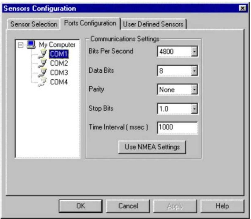
The Bits Per Second, Data Bits, Parity, and Stop Bits settings must be set exactly the same as on the system to which you will be exporting data.
You can click on the Use NMEA Settings button to set all of the above settings to the standard settings used for NMEA devices (4800, 8, N, 1)
4.59.6 Head Settings Dialog Box
The Head Settings dialog box has the following pages (note that some of these will only appear if your active head supports their functionality):
Scan
Transmit
Info
TVG Page
4.59.6.1 Head Settings: Scan
The Head Settings: Scan page allows you to determine how the head will scan.

The Scan Mode box allows you to select one of the following display modes:
Horizontal Provides a 360 degree plane of coverage for general search.
Bow Up Provides a sector up plane of coverage of 180 degrees with the center at the bottom of the screen. You can change the scanned sector width by using the Sector Heading and Width controls.
Vertical Fan Provides a vertical section of the underwater bottom conditions on the entire screen. Coverage is up to 180 degrees. You can change the scanned sector width by using the Sector Heading and Width controls.
Echo Sounder Provides a fixed echo foam displaying fish echoes below and around
the vessel.
Horizontal/Vert Fan
Provides a 180 degree Horizontal Sector main display with a Vertical Fan display in a second window. This allows the operator to observe the history of fish movement and distribution in real time. The Vertical Fan provides the range, depth, and heading of the fish echoes.
Horiz with History
Provides a 180 degree Horizontal Sector main display with the history displayed in a second window. This allows the operator th observe the history of fish movement and distribution equivalent to about four full 360 degree scans. It is also useful for detecting bottom fish and reefs.
The Scan Speed box allows you to choose the scanning speed for the head. The slower scan speeds will generate the nicest looking images.
The Pause Head button will make the head stop scanning and pinging.
The Sector controls allow you to adjust the Heading of the area to be scanned as well as the Width of the sector. Use the slider controls or the increase-decrease buttons for either adjustment. The area to be scanned is shown graphically above these controls.
Tilt controls allow you to control the tilt angle of the transducer up or down. The Auto Tilt Step option enables the automatic stepping of the tilt axis at the end of each azimuth sector sweep. As an example, if this option is enabled, after the azimuth axis has stepped through its complete sector width, the tilt axis is stepped by as much as its Step size, and the azimuth starts to sweep back its sector width in the reverse direction. Max and Min slider bars control the sector limits of the tilt axis. These limits are equivalent to sector width and heading and determine the sweep sector of the tilt.
Stabilization control enables the automatic tilt angle adjustment with the overall Pitch and Roll angle of the head. If the head is equipped with pitch and roll sensors, then prior to each acoustic ping the head reads its pitch and roll angle, calculates the offsets required to maintain the transducer at its desired angle and changes the tilt angle to compensate.
4.59.6.2 Head Settings: Transmit
The Head Settings: Transmit page is used to determine how the head transmits and receives.

The Uplink Baud Rate control is used to set the rate at which data is sent from the head to the surface. You will normally want to set this control to as high a rate as your system will support without generating too many errors.
When Compression is set to On, the color depth of the sonar image will be an eighth of its maximum through a reduction in the signal amplitude resolution. This however, increases the uplink speed of the sonar data, thereby increasing system performance. The option can usually be set to On due to negligible effect of the loss in color depth.
The Pulse Length control can be used to set the desired transmit pulse length on heads that support this feature. Generally, a shorter pulse length will give a sharper image but with reduced range. By default, the system adjusts the pulse length at different range and display mode settings according to the selection of the Optimize resolution or Maximize Range. The automatic selection of the pulse length can be disabled by clicking the Manual Setup box.
Bandwidth is used to adjust the analog bandwidth of the received signal. This option is only available for analog telemetry sonar heads. An Analog Interface Module (AIM) is required to be able to run an analog telemetry sonar head with this system. The control selections are
Narrow, Medium, Wide and Automatic. The actual bandwidth frequencies depend on the telemetry frequency. If the Automatic option is selected, then the system selects the optimal bandwidth depending on the current value of the pulse length. Note that the narrower the bandwidth, the less signal is fed through which results in a less noisy image. By the same token, image strength is reduced at narrower bandwidths.
Transducer option is only available for heads equipped with remote switch able Fan-Cone transducer. It changes the active beam shape between a conical (symmetrical) and Fan (Asymmetrical in orthogonal direction).
The Transmitter control is used to select the transmitter source for heads that are equipped with a remote control transmitter switch. In the case of an altimeter (1007 Echo sounder), the Options are Off (listen only), On, or Test (calibrated test tone for factory testing). For the new 1071 based analog sonar heads, the Test tone is automatically selected if the transmitter is turned off in low Power mode. For normal operation of the sonar head, the transmitter should always be left On.
Power controls the current transmit power output.
The Panel Gain control is used to adjust the overall gain for the image from this head.
The Range control is used to set the display range.
The Hardware Head Sync control is not used with the SL35.
The Acquisition Resolution control is used to change the number of samples collected from the sonar head to twice its normal value. The data is acquired and recorded in high resolution but not necessarily displayed in high resolution. To display the data in high resolution, the display resolution must be set to High on the image control bar (see the Control Panel). Note that the screen resolution must be able to support a minimum of 960x960 pixels, otherwise the system automatically displays the sonar data in low resolution, even if collected in high acquisition resolution.
4.59.6.3 Head Settings: Info
This page shows the calibration results as well as some hardware information about the sonar head.

The Calibration results reflect the positional accuracy of the optical sensors in the rotary scanning heads. Calibration data is not displayed for non-rotation heads such as altimeters
The optical sensors are used to estimate the current rotational angle of the transducer within the dome. The CW and CCW columns are the detected ClockWise and CounterClockWise position of the optical sensors with respect to the 0 degree reference marker on the head. The values are in 0.225 degrees. Theoretically the CW and CCW values should be the same and at perfect 0, 400, 800 and 1200 (corresponding to 0, 90, 180 and 270 degrees respectively). However, due to optical sensor mounting errors the positions do not match the perfect counts. Also due to the optical view field of the sensors, the CW and CCW values are not equal. Variation between the CW and CCW at each quadrant should be less than 20. Positional errors of each quad from its perfect value should be less than 35. Values outside these limits should be reported to Kongsberg Simrad Mesotech or its representatives.
Example:
Ref CW CCW
0 0 1596 normal
90 390 415 abnormal, but operable
180 825 845 severely abnormal
270 1190 1201 normal
In the above example, at 0 degree reference angle, everything seems to be normal. At 90 degrees reference angle, the CW position is within acceptable tolerances (only 10 steps away from perfect, the acceptable deviation is 35) The CCW is also acceptable. However, the difference between the CW and CCW is more than the acceptable 20 steps. At 180 degrees, the absolute position of the Optical Sensor is outside the acceptable 35 steps (there is a 75 step placement error). Even under the above conditions, the system will attempt to operate the sonar head; But rotational and pointing errors are inevitable.
The part number, serial number and the software versions may be used when contacting our representatives for information. The software version of the head is used internally by the system to enable different features such as profiling, synchronization, etc.
Use the Read Cable Voltages button to initiate a telemetry cable voltage measurement on analog systems (through TTM). The result may be viewed through the Customize Gauge Window with "Cable Voltage" entry added.
4.59.6.4 Head Settings: TVG
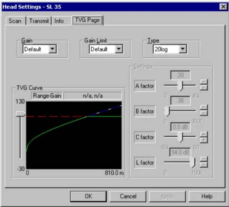
Type is a lists of TVG curves provided for the user to choose from. Selections include the standard, 20Log, 30Log, and 40Log curves which are primary used to adjust the overall signal gain. The Test TVG produces a linear gain with a slope of 1 dB per meter. This is used for receiver inspection and test. The User option provides full adjustment capability to the user to generate special gain curves (Should be used with care). When the User TVG type is selected, the TVG settings control are enabled and provide the user with the means for adjusting individual components.
Gain control is used to apply a DC gain to the standard curves. This control is disabled for Test and User TVG types.
Gain Limit controls the maximum gain of the standard curves. This control is disabled for Test and User TVG types.
Settings is enabled only when the User TVG type is selected. It provides the user with controls to adjust the TVG factors. L factor sets the maximum gain (gain Limit). The C factor is used to adjust the gain offset. This is the only control available for the 1007 altimeter sonar.
TVG Curve shows the current gain curve (updated dynamically) as adjustments are made. The slider bar on the left side of the curve can be used as a measuring bar to find the exact gain at a given range. Note the curve is shown up to the current operating range.
4.59.7 Machine Name Dialog Box

The Remote Machine Name field will be empty if this is the first time a connection to server is made on this machine. Machine name will be remembered the next time user wants to make a server connection. Once the connection is established, the remaining menu items become enabled. In case of error, an error message box will appear, informing the user of the failure. The error is also reported in the error message log.
Remove Name can be used to delete selected remote machine names. System would ask for confirmation of the request to remove a name from the list.

4.59.8 Parameters Dialog Box
The Parameters dialog box has the following pages:
Units of Measure allows you to select units of measure for the system.
Sound Velocity allows you to calculate and enter a sound velocity value.
Magnetic Variation allows you to input a static value for magnetic heading offset.
4.59.8.1 Parameters: Magnetic Variation
The Parameters: Magnetic Variation page is use to set the local Magnetic Variation.
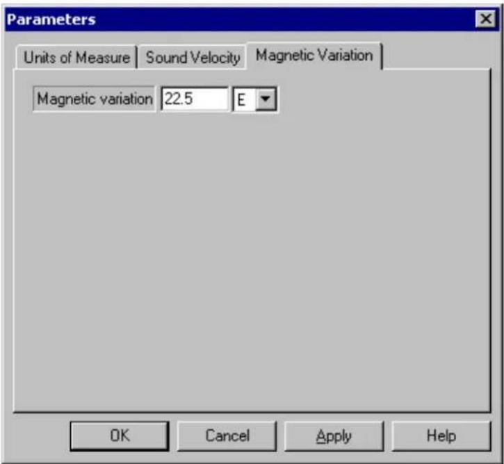
In this example, the variation for Vancouver B.C. has been entered. The variation is about 22.5 East in this area.
The entered value will be used to correct NMEA magnetic headings to true headings.
4.59.8.2 Parameters: Sound Velocity
The Parameters: Sound Velocity page is used to calculate and enter a value for the velocity of sound in water.

The Calculate from Temperature, Salinity, Depth box allows you to estimate the sound velocity in water. Enter the water Temperature, Salinity and Depth, then click the Calculate button.
You can also force the system to use a specific sound speed by entering it in the Sound Speed box in the Value to be used: section.
4.59.8.3 Parameters: Units of Measure
The Parameters: Units of Measure page is used to select the preferred units of measure for the system.

4.59.9 SL35 Properties Identity (Windows NT/2000)

The SL35 Properties Identity page should be set as above.
4.59.9.1 SL35 Properties Location (Windows NT/2000)
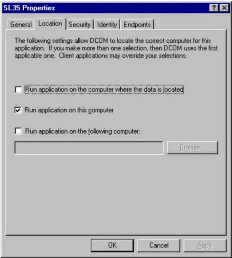
The SL35 Properties Location page should be set as above.
4.59.9.2 SL35 Properties Security (Windows NT/2000)
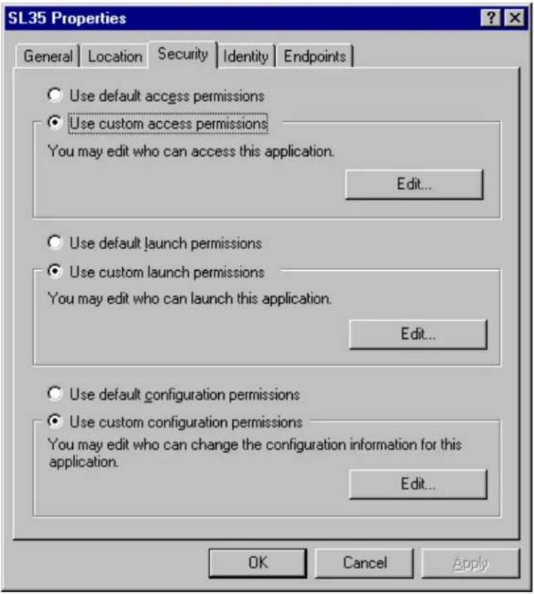
The SL35 Properties Security page should be set as above.
4.59.10 Playback Data Dialog Box
Pressing the Play Button on the Toolbar displays the Playback Data dialog box, which allows you to select a file of sonar data to playback on the system.
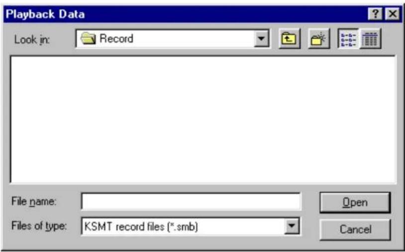
4.59.10.1 Read Event Log File Dialog Box

4.59.10.2 Record Data Dialog Box
The Record Data dialog box allows you to select a filename and location in which to store the
sonar data from the selected head.
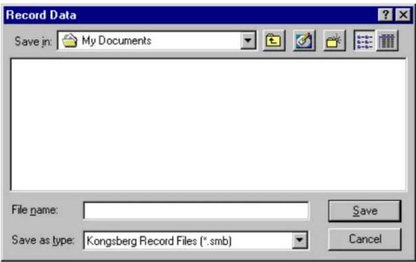
4.59.10.3 Record Dialog Box
The Record dialog box allows you to select a head from which to record data and a location to store the data.
In the Select Receivers area, press the Select File button to open the Record Data Dialog Box where you can select a filename and location to store the data.
The SL35 records data in multiple volume (files) This facilitate an easy way of transporting (machine to machine) sections of recorded files. The Max Size combo box determines the size of each recording volumes. It is highly recommended to use the default 1.44 Meg size to be able to copy individual volumes on a single floppy. This has very little effect on the recording length of time. There is a total of 1000 volumes per file name which adds to a total of 1 gigabyte recording session.
In the Select Sources area, select the head and sensors (if available) from which you want to record. Note that by default, all sources are selected for recording. You should manually select the specific source and uncheck the Select option to disable recording from that source.
The Automatic File Naming option provides the user with automatic name generation for the recorded file. The file name is generated based on the date and time of the record session as shown "Month Day, Year, Hour-Minute-Seconds" Month is the abbreviated followed by the two digit day with no space in between. The year is then separated by commas on both sides followed by the two digit representation of the hour, minute and seconds. The extension starts with an ".smb" and increments by one to ".001", ".002", etc. as the new volumes are
generated while the recording is in progress.
4.59.11 User Configuration Dialog Box
This dialog box allows the user to change, remove or define new users. It also lists most of the system settings associated with the selected user configuration. The Generic user is the default and can not be removed from the list of users. Note that changing the active user restarts the sonar system with a soft reboot.
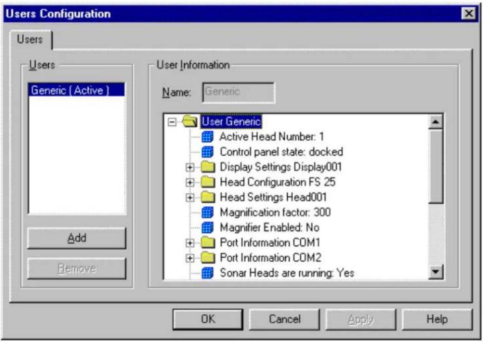
4.59.11.1 File Types Used by the SL35 System
The SL35 uses binary files with the .smb extension for recording and playback. These files are used in multiple volume configuration where, the file name is maintained and the extension is modified to reflect the volume number. As an example, a recording session may have taken a few hours which could result in a 10-volume data file. The first file is indicated by the extension .smb and the subsequent files with extensions 001, 002, 003, 004, 005, 006, 007, 008, 009.
The SL35 uses text files for exporting sensor data. It also creates a text file for logging system
messages. The contents of this file can be seen by using the System Messages Log Dialog Box. This can be opened from the View Menu.
4.59.12 Factory Reset Settings
The Factory Reset settings are as follows:
Sector Train Heading 0 degrees
Sector Width 360 degrees
Step Size X8 degrees
Range 100 meters
Gain 50 (40%)
Profiling Disabled
XDCR Orientation Up
Display Mode HORIZONTAL
Telemetry Baud Rate 57600
Automatic pulse length selection enabled for maximum resolution
All overlay colors RED.
Sector Display orientation Up
Display Gain 100%
Grids Enable
4.59.13 Gauge Windows: Customize
This dialog is used to customize gauge windows.

The Gauge Windows List Control contains a set of gauge windows available for duplication and / or modification. The system gauge windows will be shown with gray icons, whereas the custom gauge you have defined will show up in yellow.
The New button can be clicked to define a new custom gauge window. After typing in the name of the new window, you will see an empty gauge window appear on top of your sonar display (behind the dialog box) and a small yellow icon will appear in the Gauge Windows list control.
Clicking the Duplicate button will duplicate the currently selected gauge window into a new gauge window whose name you specify.
The Remove button can be used to delete custom windows that are no longer needed.
Once a custom gauge window is selected, the Add and Remove buttons will become enabled. If you wish to add parameters to the gauge window, select the desired parameters from the Unused Parameters List Control (the one of the right) and click Add. If you wish to remove parameters, select them in the Used Parameters List Control and click the Remove
button.
Any custom gauge windows that you define will appear under the Gauge Windows Menu along with the Pointers, Cursors, and Head Settings gauge windows.
4.59.14
Magnifier
Window
This is a pixel magnification window and not a true zoom. The magnification factor can be changed dynamically irrespective of the magnifier window size. The magnifier is centered on the current position of the mouse. The bigger the magnifier window size, the more of the original image can be viewed. You can use the magnifier during target measurements to get a better look at the target.

4.59.15 Cursors Gauge Window
The Cursors gauge window shows the range and bearing from the transducer to each of the
two Reference Cursors. The delta values are the range and bearing from Reference Cursor 1 to Reference Cursor 2.
This is the SL35 Cursors window.

4.59.16 Pointer Gauge Window
This gauge window displays the current range and bearing of the mouse within the sonar window with respect to the sonar head.

4.59.17 Target Position Gauge Window
The Target Position gauge window shows the latitude and longitude of a target.

4.59.18
Overload
Counter

This dialog box displays the percentage of sonar samples that are in saturation. The display is logarithmic in nature, where 10% count is displayed as half scale and 100% as full scale. For heads that support down load TVG, the user is encouraged to adjust the TVG to minimize the number of saturated samples.
4.59.19 Playback Progress Display

Only available during Playback mode. Displays the current position of the data within the playback file in a percentage of the total size of the constituent volumes. It also allows the user to view the date and time of recording as well as provide the user with the ability to reposition and view different parts of the playback file. Repositioning is done through the slider bar. The markers on top of the slider bar correspond to the beginning of each volume. The "Restart from beginning of Volume" option can be used to always start at the beginning of a volume during a repositioning step. This is the default and is a much faster positioning procedure. If this option is disabled, the system fast forward through the selected volume to the user selected position within that volume. Note that during this auto-search period, the mouse is restricted to a small box within the playback progress dialog box to prevent any other user action. The "Continuous" option enables the system to continuously playback the same file over and over again. This is particularly useful when the operator is trying to setup profiling parameters during playback.

4.59.20 Scope Graph Display
In a scope graph display, image data is plotted as a vertical bar whose color and width varies with signal strength. The vertical dimension represents range. The horizontal width and plot color represents received signal strength.
4.59.21 Security Key Warning
Note that the security Key (Dongle) has to be attached to the printer port if you want to run a head, otherwise, the system will prompt the user with

We provide the user with an emergency password that can bypass the security key for a fixed
number of hours. This is a one-time-only operation and cannot be repeated on a computer after the expiry of the operational hours, even with a new dongle. The user must call the Mesotech office with the serial number of the dongle to obtain a 16 hexadecimal character password. Once the system prompts with the "Key is not connected" message, you can press "Ctrl + Alt + E" key sequence to pop up the password dialog box. You must press all three keys "Ctrl", "Alt" and "E" at the same time on the keyboard.

4.59.22 Sensors Configuration Dialog Box
The Sensors Configuration dialog box can be brought up by selecting Sensors from the Configuration Menu. It consists of the following three property pages:
Sensor Selection
Ports Configuration
User Defined Sensors
4.59.22.1 Sensors Sensor Selection
The Sensors Sensor Selection page is used to select sensors such as NMEA devices to be read by the SL35.
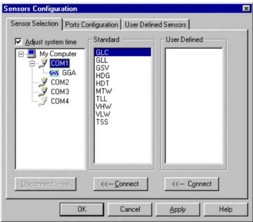
To add sensors to a COM port:
1) Select an available COM port in the tree under My Computer.
2) You can select one or more of the NMEA sentences in the Standard section. Press the Connect button below this list to connect the selected standard sensors. The names of the selected sensors will appear in tree below the selected COM port.
3) If you have User Defined sensors, you can select one or more of them. Press the Connect button under this list to connect them to the selected port.
To remove a sensor from a COM port:
1) Select the sensors to be removed by clicking on it in the tree under My Computer.
2) Press the Disconnect button.
Adjust System Time: option allows the system clock to be synchronized to the incoming time of the NMEA sensor data. As a consequence all internal data time stamps would match that of the sensor data. This may prove very useful for reconstructing geometrically correct data
during the post processing of the exported profile data.
4.59.22.2 Sensors Ports Configuration
The Sensors Ports Configuration page is used to configure the communications settings of the COM ports used for sensor input.

Select the COM port that you want to configure in the tree under My Computer.
You must set each of the Communications Settings (Bits Per Second, Data Bits, Parity, and Stop Bits) to match that of the sensor you are trying to connect with.
Set the Time Interval to the rate at which you want the sensors to be checked for new data.
You can press the Use NMEA Settings button to quickly set all of the communication settings to those normally used by NMEA devices.
4.59.22.3 User Defined Sensors
The User Defined Sensors page of the Sensors Configuration dialog box is used to specify the data formats from user defined sensors.

Press the Create button to make a new user defined sensor. This will automatically be given the name US1 for the first sensor, US2 for the second, etc. You can change the assigned name to what ever you want by editing the contents of the Name edit box.
Start Character
This edit box allows you to select the Start Character of the user serial string.
Field Delimiter
This box allows you to select the Field Delimiter character, typically a comma or space.
Format
The Format box allows you to select which characters in the input string will be displayed and how they will be interpreted. You must enter some sequence of the letters A,B,F,I,N,D, or S to define the display format.
A Print as ASCII character
B Print as BCD character
F Search for next Field Delimiter
I Ignore character
N Print as ASCII to next Field Delimiter
D Insert Decimal Point
S Insert Space
Example
Suppose you had a device which provided distance traveled through the water using the
NMEA defined VLW sentence:
\$--VLW,x.x,N,x.x,N*hh
where:
\$--VLWidentifies the start and type of sentence,
x.x is a variable length data field showing the cumulative distance traveled through the water.
N specifies the distance units to be in nautical miles,
x.x is a variable length data field showing the distance since reset,
N specifies the distance units to be in nautical miles,
*hh is a checksum,
This sentence always starts with the \character, so we would set the Start Character for this data to \(Hex 24 or Binary 00100100).
The data is separated into fields using commas, so we would set the Field Delimiter for this data to , (Hex 2C or Binary 00101100).
Suppose we wanted to display only the cumulative distance and the distance since reset from this data string. We could set the Display Format string to FNFSSN. The first F would ignore everything up to and including the first comma, the first N would display the cumulative distance field, the next F would skip the next field, the SS would print two spaces to separate the data, and the final N would display the 'distance since reset' field.
4.59.22.4 Sensors Data Display Box
The Sensors Data display box shows the data being collected through the serial ports. The number of entries displayed, is updated as the user modifies the type of sensors to input from the serial port through the Sensor Selection dialog box accessed through the Configuration | NMEA Setup.... menu

4.59.23 System Configuration Dialog Box

For the information on the "System Configuration" Setup procedure, see Part 6.
4.59.24 System Message Log Dialog Box
The System Message Log dialog box displays a list of messages that may be helpful in diagnosing problems with the system.
Note that a copy of this is stored in a text file (Messages Log) that is stored under the Logs directory automatically created in your current operational directory. The file is cleared every time the sonar system is running. However, a copy of the last four log files is created before clearing the new one. In this way there is always a copy of the last four sessions of the sonar operation as well as the current one on your machine.

4.60 AUDIO SET-UP WINDOW

4.61 POST PROCESSING SET-UP WINDOW
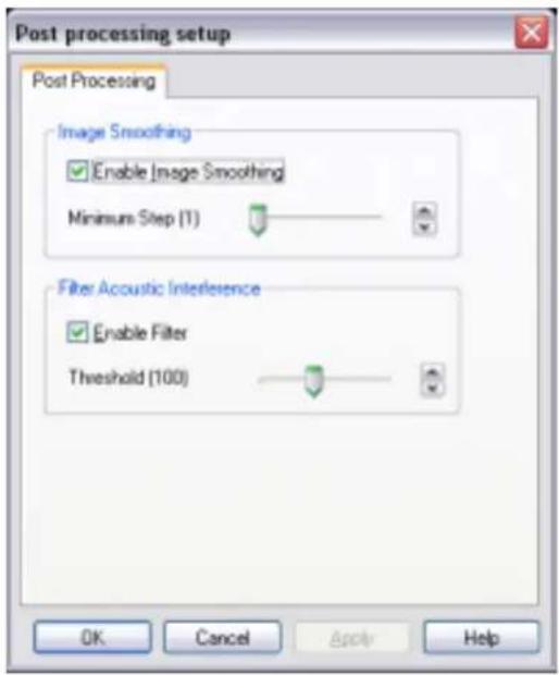
4.62 AUDIO AND POST PROCESSING SET-UP PROCEDURE
The Audio and Post Processing set-up instructions are located in Part 6, Paragraph 7.
PART 5
SELECTING SETTINGS
5. SELECTING SETTINGS ....5.3
5.1 OVERVIEW 5.3
5.2 DEFINE USER / OPERATION SETTINGS 5.3
5.2.1 User 1 Settings ....5.3
5.2.2 User 1, Operation 1 Settings....5.4
5.2.3 Creating Operation 1, 2, 3 and 4 Settings....5.5
5.3 DISPLAY MODE....5.6
5.3.1 Horizontal Display Mode with Control Panel....5.6
5.3.2 Horizontal Display Mode without Control Panel....5.7
5.3.3 Bow Up Display Mode....5.8
5.3.4 Vertical Fan Display Mode without Control Panel....5.9
Vertical Fan Display Mode with Control Panel....5.9
5.3.5 Sounder Display Mode without Control Panel 5.10
5.3.6 Horizontal with History Display Mode....5.11
5.3.7 Horizontal with Strata Display Mode....5.11
5.3.8 Horizontal with Strata and Control Panel Display Mode .....5.12
5.4 NEW DISPLAY MODE....5.13
5.4.1 Dual Sonar Bow-Up and Catch Display Mode....5.13
5.4.2 Dual Sonar Catch Display Mode 5.14
5.4.3 Catch Display Mode....5.15
5.5 TILT ANGLE SETTINGS 5.16
5.5.1 Discriminating Fish Echoes....5.16
5.5.2 Tilt Angle and Beam Coverage 5.17
5.6 PITCH AND ROLL CALIBRATION....5.17
5.7 KEY SETTINGS....5.17
5.7.1 AGC Setting....5.17
5.7.2 RX Gain Response Setting....5.18
5.7.3 RCG Setting....5.18
5.7.4 Pulse Length Setting....5.18
5.7.5 Optimize Resolution....5.18
5.7.6 Maximize Range 5.19
5.7.7 Peak Detection 5.19
5. SELECTING SETTINGS
5.1 OVERVIEW
The following section will provide help in the selection of appropriate settings for most fishing conditions.
5.2 DEFINE USER / OPERATION SETTINGS
After you have completed the system configuration as per Part 6, paragraph 6.6.13 "User Settings", you should re-define your custom user 1, 2, 3 and 4 settings.
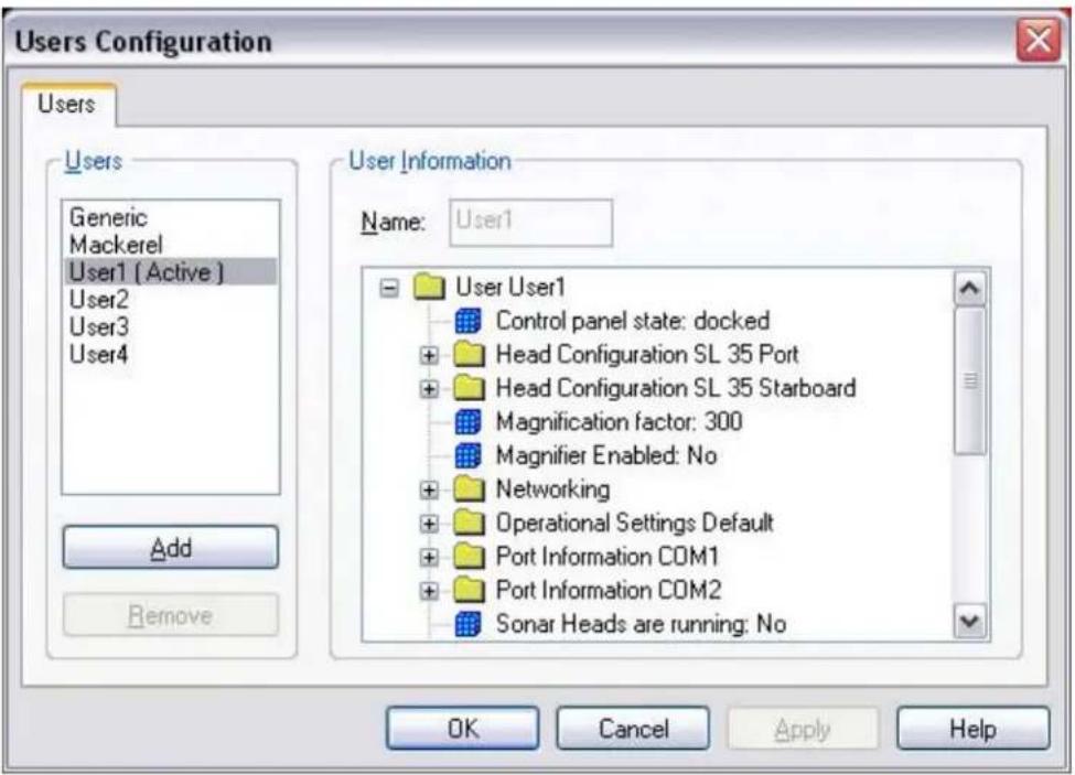
5.2.1 User 1 Settings
The "User 1" setting should be saved as the standard operating mode, the same as the "Generic" or saved as the settings from the seatrial.
The "User 1" software installed in the processing unit is saved with the same settings as "Generic". The "GENERIC" (Factory Setting) can not be changed by the operator. To overwrite the "User 1" settings protection you will have to press the "U" key and the "1" key at the same time, then Click on OK. Repeat the same process for U2, U3 and U4. If you try to overwrite the User settings without holding the U1, U2, U3 or U4 the following window will be displayed.

5.2.2 User 1, Operation 1 Settings
Following the set-up of "User 1" Setting, the Operation 1, 2, 3 and 4 must be set-up. The "Operation 1, 2, 3 and 4 coordinate with the "User 1, 2, 3, and 4 buttons located on the operation panel".

5.2.3 Creating Operation 1, 2, 3 and 4 Settings
Assuming you are working on setting-up "User 1", which means the active User is "User 1".
- Go to menu "Configuration", select "Operation Setting", Click on "Define"
- Next, Click on "Add", "Operation 1" should be added, then Click on "OK"
- Next Click on the "Run" Icon and setup the operation mode, Range, Gain, Tilt, Scan Speed, Display Mode, etc. you want to have when you press the "User 1" key located on the operator panel.
- Next "Pause" the sonar by Clicking on the "Pause Sonar Icon"
- Then go to "Configuration, next "Click" on "Save Settings"
The "Save Configuration" dialog window will pop-up
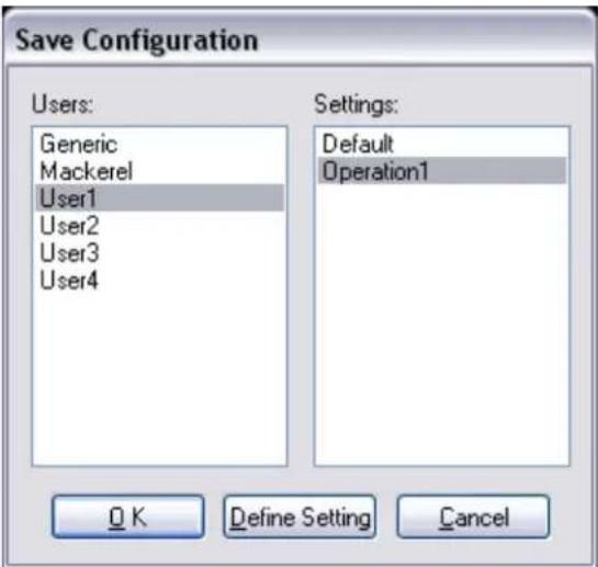
Just Click "OK", this will save your "Operation 1" settings in the "User 1"
Repeat the same procedure for setting up your "Operation 2, 3 and 4.
5.3 DISPLAY MODE
The following figure below shows the typical Display Mode available on the SL 35 Hull Sonar.
5.3.1 Horizontal Display Mode with Control Panel
![SL 30/35 - [SL 35 Part] File View Configuration Operation Targets Network Window Help Range: 200 m Gain: 7.4 %n Heading: 0 ° Tilt: -7 ° Scan Speed: 3.6° Grid Scale: 40 m/div Stabilization: Off Auto search: Off SL 35 Part 1 Range: 200m Scan 71.1% Till Angle: 7° Sides Heading: 0° Width: 200° Scan Speed: +16 (3.8°) Soil Speed: Normal For Help, press F: START 0.00 PM - 10 PM Microsoft Word - 16.0 5:00 PM](/content/2026/05/868320/images/191ec429ae7824b67349e83a345840ee45a9c2357374624097baaf779be5a8ea.jpg)
5.3.2 Horizontal Display Mode without Control Panel
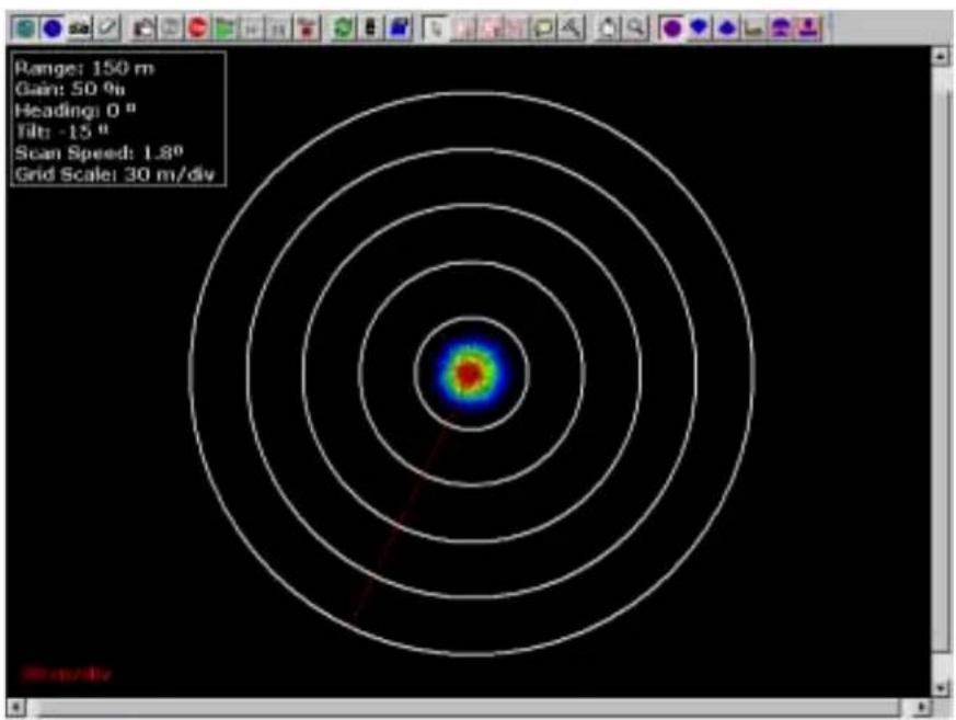

radar
| Angle (°) | Velocity (m/div) | | --------- | ---------------- | | 0 | 0 | | 30 | 5 | | 60 | 10 | | 90 | 15 | | 120 | 20 | | 150 | 25 | | 180 | 30 | | 210 | 35 | | 240 | 40 | | 270 | 45 | | 300 | 50 | | 330 | 55 | | 360 | 60 | | 390 | 65 | | 420 | 70 | | 450 | 75 | | 480 | 80 | | 510 | 85 | | 540 | 90 | | 570 | 95 | | 600 | 100 | | 630 | 105 | | 660 | 110 | | 690 | 115 | | 720 | 120 | | 750 | 125 | | 780 | 130 | | 810 | 135 | | 840 | 140 | | 870 | 145 | | 900 | 150 | | 930 | 155 | | 960 | 160 | | 990 | 165 | | 1020 | 170 | | 1050 | 175 | | 1080 | 180 | | 1110 | 185 | | 1140 | 190 | | 1170 | 195 | | 1200 | 200 | | 1230 | 205 | | 1260 | 210 | | 1290 | 215 | | 1320 | 220 | | 1350 | 225 | | 1380 | 230 | | 1410 | 235 | | 1440 | 240 | | 1470 | 245 | | 1500 | 250 | | 1530 | 255 | | 1560 | 260 | | 1590 | 265 | | 1620 | 270 | | 1650 | 275 | | 1680 | 280 | | 1710 | 285 | | 1740 | 290 | | 1770 | 295 | | 1800 | 300 | | 1830 | 305 | | 1860 | 310 | | 1890 | 315 | | 1920 | 320 | | 1950 | 325 | | 1980 | 330 | | 2010 | 335 | | 2040 | 340 | | 2070 | 345 | | 2100 | 350 | | 2130 | 355 | | 2160 | 360 | | 2190 | 365 | | 2220 | 370 | | 2250 | 375 | | 2280 | 380 | | 2310 | 385 | | 2340 | 390 | | 2370 | 395 | | 2400 | 400 | | 2430 | 405 | | 2460 | 410 | | 2490 | 415 | | 2520 | 420 | | 2550 | 425 | | 2580 | 430 | | 2610 | 435 | | 2640 | 440 | | 2670 | 445 | | 2700 | 450 | | 2730 | 455 | | 2760 | 460 | | 2790 | 465 | | 2820 | 470 | | 2850 | 475 | | 2880 | 480 | | 2910 | 485 | | 2940 | 490 | | 2970 | 495 | | Note: The 'Radial' label indicates the direction of the circle in the ring chart. The 'Velocity' label indicates the radius of the circle in the ring chart. There is no additional data series in this image. The values are estimated based on the current value of the circle. The last row is a duplicate of the first row to close the circle. The rest of the circle is empty. The values are estimated based on the current value of the circle. There is no additional data series in this image.5.3.3 Bow Up Display Mode
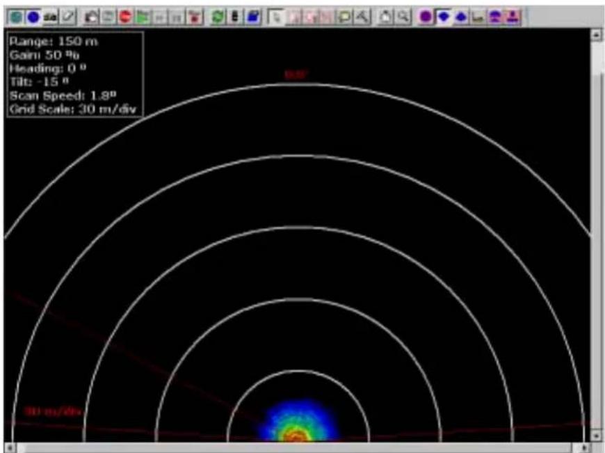

radar
| Angle (°) | Velocity (m/div) | | --------- | ---------------- | | 0 | 0.0 | | 45 | 0.2 | | 90 | 0.4 | | 135 | 0.6 | | 180 | 0.8 | | 225 | 1.0 | | 270 | 0.8 | | 315 | 0.6 | | 360 | 0.4 | | 405 | 0.2 | | 450 | 0.0 |5.3.4 Vertical Fan Display Mode without Control Panel

Vertical Fan Display Mode with Control Panel

5.3.5 Sounder Display Mode without Control Panel
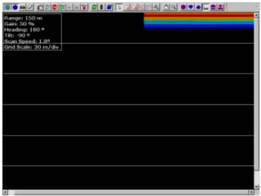

line
| Time (s) | Value | | -------- | ----- | | 0 | 0 | | 1 | 0 | | 2 | 0 | | 3 | 0 | | 4 | 0 | | 5 | 0 | | 6 | 0 | | 7 | 0 | | 8 | 0 | | 9 | 0 | | 10 | 0 | | 11 | 0 | | 12 | 0 | | 13 | 0 | | 14 | 0 | | 15 | 0 | | 16 | 0 | | 17 | 0 | | 18 | 0 | | 19 | 0 | | 20 | 0 | | 21 | 0 | | 22 | 0 | | 23 | 0 | | 24 | 0 | | 25 | 0 | | 26 | 0 | | 27 | 0 | | 28 | 0 | | 29 | 0 | | 30 | 0 | | 31 | 0 | | 32 | 0 | | 33 | 0 | | 34 | 0 | | 35 | 0 | | 36 | 0 | | 37 | 0 | | 38 | 0 | | 39 | 0 | | 40 | 0 | | 41 | 0 | | 42 | 0 | | 43 | 0 | | 44 | 0 | | 45 | 0 | | 46 | 0 | | 47 | 0 | | 48 | 0 | | 49 | 0 | | 50 | 0 | | 51 | 0 | | 52 | 0 | | 53 | 0 | | 54 | 0 | | 55 | 0 | | 56 | 0 | | 57 | 0 | | 58 | 0 | | 59 | 0 | | 60 | 0 | | 61 | 0 | | 62 | 0 | | 63 | 0 | | 64 | 0 | | 65 | 0 | | 66 | 0 | | 67 | 0 | | 68 | 0 | | 69 | 0 | | 70 | 0 | | 71 | 0 | | 72 | 0 | | 73 | 0 | | 74 | 0 | | 75 | 0 | | 76 | 0 | | 77 | 0 | | 78 | 0 | | 79 | 0 | | 80 | 0 | | 81 | 0 | | 82 | 0 | | 83 | 0 | | 84 | 0 | | 85 | 0 | | 86 | 0 | | 87 | 0 | | 88 | 0 | | 89 | 0 | | 90 | 0 | | 91 | 0 | | 92 | 0 | | 93 | 0 | | 94 | 0 | | 95 | 0 | | 96 | 0 | | 97 | 0 | | 98 | 0 | | 99 | 0 | | Note: The '4 m/div' label is not present in the image. The 'Y' label is '4 M/div'.5.3.6 Horizontal with History Display Mode

5.3.7 Horizontal with Strata Display Mode

5.3.8 Horizontal with Strata and Control Panel Display Mode

5.4 NEW DISPLAY MODE
The following figure below shows the typical New Display Mode available on the SL 30 and the SL35 Hull Sonar.
5.4.1 Dual Sonar Bow-Up and Catch Display Mode

The Port Window illustrates the SL30 or SL35 in a Bow Up Mode and the Starboard Window illustrates the second SL30 or SL35 sonar set-up in a Catch Mode.
5.4.2 Dual Sonar Catch Display Mode
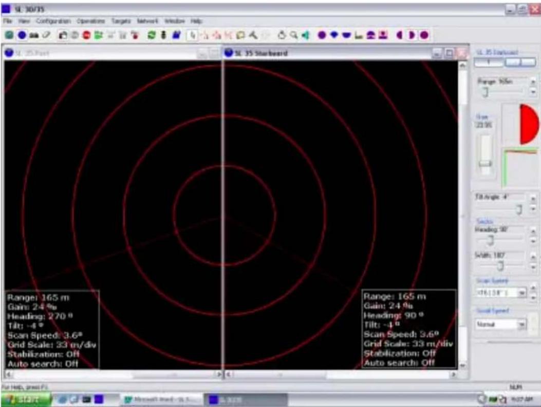
The Port Window illustrates the SL30 or SL35 in a Catch Mode; the Starboard Window also illustrates a second SL30 or SL35 in the Catch Mode. This demonstrates how the sonars combine to give full coverage on both sides simultaneously.
5.4.3 Catch Display Mode
![UL 30/35 - [UL 35 Starbeard] File Edit Configuration Operations Targets Network Window Help Range: 165 m Gains: 24 % Heading: 90 ° Tilt: -4 ° Scan Speed: 3.6° Grid Scale: 33 m/div Stabilization: Off Auto search: Off For help, guess F: Start Microsoft Wind-up 100% 100% 100% 100% 100% 100% 100% 100% 100% 100% 100% 100% 100% 100% 100% 100% 100% 100% 100% 100% 100%](/content/2026/05/868320/images/68e9ee55c3dd9c87343bfa4b038774c59651ce7e2f2db4e7d037dfa817bf462a.jpg)
The SL30 or SL35 Starboard Window set-up in a Catch Mode.
5.5 TILT ANGLE SETTINGS

natural_image
Simple line drawing of a boat deploying or landing a curved surface over water (no text or symbols)Selecting the proper "Tilt Angle" for surface or bottom fish echoes will depend on the Tilt Angle you have selected. The recommended tilt angle for surface fish should be a narrow angle approximately (5 degrees) and for bottom fish, a wide angle approximately (30 degrees)
5.5.1 Discriminating Fish Echoes
- Tilt angle 0 degree to 8 degrees:
Using this tilt angle, you may or may not capture the bottom since the returned echoes are weak.
- Tilt angle 10 degrees to 20 degrees
Using this tilt angle, you will only display half of the bottom since the lower halves of the sonar beam only capture it.
- Tilt angle 20 degrees to 40 degrees
Using this tilt angle, you will display the entire bottom since the full width of the beam is captured.
5.5.2 Tilt Angle and Beam Coverage
The figure below illustrates the vertical beam width "foot print" of the sonar at different ranges

5.6 PITCH AND ROLL CALIBRATION
For the procedure to calibrate the Pitch and Roll offset, refer to Part 6, paragraph 6.6.11
5.7 KEY SETTINGS
The following section will explain some of the key settings for the SL 35 Hull Sonar in order to maximize the performance.
5.7.1 AGC Setting
The Automatic Gain Control “AGC” algorithm increases the gain during the low acoustic return and reduces the gain during strong acoustic returns. The speed with which the gain is adjusted is determined by the setting of the “RX Gain Response” as explained in the next paragraph.
5.7.2 RX Gain Response Setting
The setting of the RX Gain Response determines the response of the filter algorithm as selected by the “RX Gain Type”. For the AGC, this setting determines the speed by which the gain is adjusted. For the RCG, this setting determines the influence of the previous ping average over the current ping. If set to Slow, the overall average is given by the sum of 20% current and 80% of previous average. In Medium this ratio is 50% to 50%, and the Fast, the ratio is 80% to 20%.
5.7.3 RCG Setting
The Reverberation Control Gain “RCG” filter senses the noise level (reverberation, propeller noise, etc.) and adjusts the gain of each received beam in order to eliminate noise on the display. The strength of the filter can be selected in the menu. With maximum strength selected, the RCG will effectively reduce the bottom in shallow water, while variation on the bottom will be displayed. Scattered fish can be perceived as reverberation.
Note: The RCG filter must be used with care if scattered schools are to be detected.
5.7.4 Pulse Length Setting
The SL 35 Hull Sonar is capable of changing the acoustic pulse length that is transmitted. The processing unit calculates the pulse length based on the operating range of the sonar. It is generally better to use a longer pulse as the operating range increases. However, the actual value can be optimized to enhance the details in the sonar image (Optimize Resolution) or increase the target visibility at long distance away from the sonar (Maximum Range). The system will automatically set the pulse length to match the range, unless manually adjusted by the operator.
5.7.5 Optimize Resolution
The pulse length selection can be optimized to enhance the detail of the targets. It has been experimentally determined that the pulse length corresponding to 40% of the sample period can increase the image resolution and details for targets that are generally larger than a few samples. This pulse length increases linearly with increasing the operating range.
5.7.6 Maximize Range
The pulse length calculation can be optimized to increase the detection range of the sonar. Generally, the longer the pulse length, the more energy is transmitted into the water, which could then travel a longer distance and not get reflected from the targets that are further away from the sonar. The pulse length corresponding to 80% of the sample period can increase the detection distance of the targets without major drain on the sonar power supply. This pulse length increases linearly with increasing the operating range.
5.7.7 Peak Detection
The Peak detection feature can only be described as follows.
The older sonar was not capable of changing the acoustic pulse length. They were generally operated at a pulse length of 100 Microseconds. This meant that at range greater than 50 meters, there would be a good chance of not detecting small targets. The reason for this is that the combination of small target size, short pulse length and long sample period could result in the acoustic return from the target to fall in between two samples and therefore not seen on the sonar image.
The remedy this, it was decided to take additional samples and select the strongest echo target for the sonar image. This is generally referred to as “Peak Detection” because we are detecting the peak value of the signal in between two samples. The user can select the number of optional samples that the system takes in order to detect the peak value.
PART 6
INSTALLATION, START-UP
AND TEST
6. INSTALLATION, START-UP AND TEST ......6.3
6.1 INSTALLATION PROCEDURE....6.3
6.2 SURFACE UNIT ELECTRONICS INSTALLATION....6.3
6.2.1 Mounting of Units....6.3
6.2.2 Power Considerations....6.4
6.2.3 Connecting the Display Unit....6.4
6.2.4 Connecting the Processor....6.5
6.2.5 Connecting the Operating/Interface unit 6.5
6.2.6 Connecting DGPS....6.5
6.2.7 Network LAN Connection....6.5
6.3 SONAR ROOM HULL AND TRANSCEIVER UNIT INSTALLATION......6.6
6.3.1 Sonar Room Mounting Space....6.6
6.3.2 Mounting the Transceiver unit....6.7
6.3.3 Mounting the Lower and Raise Hoist Unit 6.7
6.3.4 Mounting the Motion Sensor 6.8
6.3.5 Mounting the Tank (Trunk) Unit 6.8
6.4 ASSEMBLING THE FLANGE, SONAR DOME, SHAFT AND TANK GUIDE6.9
6.4.1 Required Tools 6.9
6.4.2 Tank Flange and Shaft Prepping 6.10
6.4.3 Assembling the Sonar Dome, Shaft and Tank Guide Assembly......6.10
6.4.4 Mounting the Flange and Sonar Dome to the Tank (Trunk) ......6.12
6.4.5 Mounting the Hoist Unit....6.13
6.4.6 Mounting the Transceiver....6.14
6.5 INTERCONNECTION WIRING DIAGRAM 6.14
6.5.1 Motion Sensor Electrical Connection....6.14
6.6 SL 30 OR SL 35 SYSTEM START-UP AND TEST....6.14
6.6.1 SL 30/35 Start Up 6.14
6.6.2 Power-Up Configuration....6.15
6.6.3 SL 30 or SL 35 Start up Procedure....6.15
6.6.4 SL 30/35 RUN UP Procedure ....6.21
6.6.5 Display Settings 6.22
6.6.6 Control Setting....6.23
6.6.7 Readout Options....6.24
6.6.8 SL 30/35 Settings 6.25
6.6.9 Transmit Setting Page 6.26
6.6.10 TVG Setting Page 6.27
6.6.11 Info Page....6.28
6.6.12 Sensor Page 6.29
6.6.13 User Setting 6.30
6.6.14 Save Additional User Operation or Specific Fishery Setting ......6.31
6.7 USER 1, 2, 3, 4 SETTINGS....6.32
6.8 AUDIO AND POST PROCESSING SET-UP....6.32
6.8.1 Post Processing....6.32
6.8.2 Audio Set-up....6.34
6. INSTALLATION, START-UP AND TEST
6.1 INSTALLATION PROCEDURE
The installation of the SL 30/35 Hull Sonar involves the following steps:
- Deciding on the locations in the wheelhouse for the surface units.
- Mounting the surface units and making the connections between the SL 30/35 Processing Unit, Keyboard/Interface Unit, the Display Unit and other optional equipment being installed.
- Assembling the Hull Unit in the sonar room.
- Mounting the Hull Unit and completing all aspects of the installation.
- Running up the system to verify proper operation, system configuration and perform initial system tests.
6.2 SURFACE UNIT ELECTRONICS INSTALLATION
The following section will describe the installation procedure for the bridge unit requirements.
6.2.1 Mounting of Units
The display unit should be located in the wheelhouse in a place that provides a good view of the screen and avoids direct sunlight, if possible. Depending on the monitor that was selected, the unit may be mounted on top or recessed into the bridge console. Simrad supplied display units include the necessary mounting brackets.
The SL 30/35 Operating Panel unit should be mounted in close vicinity to the operator's position in the wheelhouse and near the display unit. The unit may be flush mounted into the bridge console.
The Processing Unit may be mounted inside the bridge console. Sufficient space should be left around the processing unit for proper ventilation.
Optional equipment for interface to the processing unit may be mounted in any convenient location, provided the user supplied interconnect cables are of sufficient length and the required power is available.
6.2.2 Power Considerations
The display unit, generally, will require 110VAC or 240VAC, 50/60Hz or 12/24CDC, +/- 10%. Depending on the capabilities of the unit chosen, it may automatically detect the supply voltage or the unit may have to be ordered for the correct voltage.
The SL 30/35 operating panel / interface unit will operate from either 110VAC or 240VAC, 50/60Hz, +/- 10%. Details on selecting the proper voltage are indicated at the rear of the unit. Failure to select the proper Input voltage will damage the internal power supply. The safety fuses must also be changed to the proper rating.
The SL 30/35, HP, COMPAQ, PC Processing unit can be operated with either 110VAC or 240VAC, 50/60Hz +/-10% input. Details on selecting the proper voltage are indicated at the rear of the unit.
6.2.3 Connecting the Display Unit
Either a VGA monitor CRT type or a Simrad LCD monitor may be connected to the SL 30/35 processing unit. Depending on which type of monitor is used, the video output type must be set accordingly.
An industry standard VGA monitor will connect directly to the miniature DB-15 connector located on the rear panel of the processing unit unit.
The SL 30/35 Processing unit has a Dual Video interface card installed as standard equipment. You must set up your display software as per your requirement. If you have only one monitor, simply plug your monitor cable into the monitor connector marked "Connector 1" on the adapter card, or Video "A" port. If you are using two monitors, you must connect the 2^nd monitor in the "Connector 2" on the adapter card, or Video "B" port. Note that the SL 30/35 processing unit must be turned "OFF" prior to connecting the second video monitor.
A User Guide manual is provided with the system, including a Recovery CD-ROM. With this CD you can recover your system as delivered, run the diagnostics. Note: The Dual video monitor software is installed at the factory, you only have to set up your monitor configuration as per Window's XP Pro.
Note!
All Device driver and utilities are preloaded on your system and provided on a Driver, Utilities and Documentation CD-ROM. This CD-ROM also includes tips for re-installing the operating system.
6.2.4 Connecting the Processor
Mount the SL 30/35 Processing unit with easily accessible power outlet and enough space for the display, keyboard, mouse, printer, and any other accessories. The connectors are shaped to go in one way only.
Note: Fixing brackets are supplied with the processing unit.
6.2.5 Connecting the Operating/Interface unit
The SL 30/35 system is supplied with a HP-PC (COMPAQ) Processing unit. Power must be turned on separately. A separate ON/Off Power Buttons is located on the Operating control panel.
6.2.6 Connecting DGPS
Connect the DGPS NMEA 183 output to the COM 2 port at the rear of the processing unit. Interconnect cable not supplied. See Part 4, paragraph 4.59.22.2 "Sensor Ports Configuration.
The pin connections for your DGPS input/output PC/RS232 are as follows:
• Pin number "2" RS-232 Rx
- Pin number "3" RS-232 Tx
- Pin number "5" GND.
6.2.7 Network LAN Connection
Your SL 30/35 comes equipped with a Network LAN interface adapter card. The LAN adapter supports both 10Mbit/s and 100Mbit/s operations and automatically detects which network type is being used. The RJ-45 plugs into your SL 30/35 optional remote workstation. LAN cables are not supplied with the system.
For additional information, please refer to the User's Guide supplied with the system.
Warning! Before applying the power to the processing unit, ensure that the proper AC or DC input voltage has been selected.
6.3 SONAR ROOM HULL AND TRANSCEIVER UNIT INSTALLATION
The following section will describe the installation procedure for the sonar room unit requirements for the SL35 Sonar. See paragraph 0.0 for the SL 30 installation.
6.3.1 Sonar Room Mounting Space
The hull unit is generally placed about 1/3 (1/2 in case of a small boat) of the ship length from the bow on the FORE-AFT line and beside the keel line (less than 1000mm from the keel line)
For a larger vessel the hull unit should be mounted as far Forward as possible to avoid turbulence.
Note: On larger vessels, a dedicated sonar room is provided.
See Part 8 “Attachment and Drawings” for the recommended mounting space drawing and overhead clearance requirement.
Small Vessel Tank Location


Within 1 meter from the keel
For small vessels, a high water pressure is created in the tank because of the resistance at the rear of the tank well. To solve this problem, attach a "Fin" to the hull at the location shown in the above figure. The "Fin" height should be approx. 1.5cm. This Fin will provide a smooth stream of water into the retraction tank
6.3.2 Mounting the Transceiver unit
The transceiver is generally mounted on the tank flange. Special mounting pads and screws are supplied to fasten the transceiver. Provision is also made to bulkhead mount the transceiver unit. Note that a maximum cable length between the hull unit to the transceiver is 5.1 meters. You must order the proper hull unit if you plan to bulkhead mount the transceiver unit.
6.3.3 Mounting the Lower and Raise Hoist Unit
The Lower and Raise Hoist unit is a self-contained hydraulic system. A mounting
pad is provided on the tank flange and a shaft clamp retainer is included. To mount the hoist unit just insert the lower and upper locating pins and hair pin clip to secure the ram in the proper location.
Note: The vent cap must be installed on the oil reservoir to insure proper operation.
A Ram guide is also provided to ensure proper Ram alignment. The Power and Upper/Lower limit switch connections must be made in the transceiver unit. A one-meter interconnection cable and crimp-on terminal lug are supplied with the hoist unit.
6.3.4 Mounting the Motion Sensor
The SL 35 roll and pitch angles motion sensor can be mounted mid-ship, away from areas subject to water splash. The ambient temperature should not exceed 50 degrees Celsius. Orient the FORE mark on the unit toward the ship's bow and mount the unit level to within 5 degrees in all directions. See paragraph. 6.6.11, for calibration procedure.
Note: 10 meters of interconnection cable from the motion sensor to the transceiver unit is standard supplied.
6.3.5 Mounting the Tank (Trunk) Unit
The owner and the dockyard, in deciding the location for the hull unit, must conclude general mounting considerations. When deciding on the proper location, the following points must be taken in to account:
- Noise and air bubbles will affect the performance (bow plane)
- Propeller noise (cavitation)
- Cruising noise
• Acoustic interference
• Electrical interference
The location must take into account the interference from other sonar or sounding equipment. The hull unit must be at least 3.0 meters away from other transducers or sounding equipment, to minimize interference.
An obstacle in the fore direction will not only cause a shadow zone, but could also aerate the water, resulting in poor sonar performance. Be sure to locate the hull unit well away from any obstacle in the fore direction. A typical mounting method is shown in the outline drawing provided in Part 8 “Attachments and Drawings” for detailed information.
When a retraction tank is constructed locally, finish it so that the welding beads do not protrude on the inner surface of the tank. The tank guide may hit the bead. Also, do not position the welding bead in the ship's fore-aft line. The final stage, when mounting the retraction tank, is to center any two bolt holes facing the ship's bow. See Part 8 "Attachment and Drawing" for detailed information.
Retraction Tank Flange
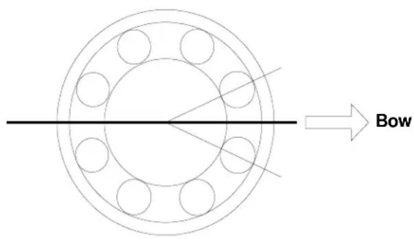
NOTE
Special attention must be paid to the safety (strength, water tightness) first, followed by ease of maintenance and inspection.
6.4 ASSEMBLING THE FLANGE, SONAR DOME, SHAFT AND TANK GUIDE
The following paragraphs will describe the assembling of the tank flange, the sonar dome assembly to the shaft and the tank guide.
6.4.1 Required Tools
The necessary tools required to assemble the following items, are listed below:
- Tank Flange: Qty 2, 30mm wrench "Not supplied"
- Shaft lock Nut Qty 2, 60mm wrench "Not supplied"
- Hoist Motor Clamp Qty 1, 5/32 inch allen key "Supplied"
- Ram Clamp Bracket Qty 1, 3/16 inch allen key "Supplied"
- Shaft V-guide and
Shaft Packing Retainer Qty 1, 1/4 inch allen key "Supplied" - Tank Guide Qty 1, 5/16 inch allen key "Supplied"
6.4.2 Tank Flange and Shaft Prepping
The tank flange comes from the factory with the shaft bearing, grease, shaft seal and scraper installed at the factory. All tank flanges are serialized and pressure tested. Great care must be taken not to damage the shaft seals and the flange gasket surface during the installation.
Calculate the necessary length of the main shaft from the length of the retraction tank and cut off the extra length if necessary. If you have to cut the shaft, refer to the shaft drawing located in Part 8 for the proper cutting procedure. If you do not follow the proper procedure, you will damage the shaft seals and shaft scraper when you pass the shaft through the main shaft bearing assembly.
See Part 8 “Attachments and Drawings” for the tank flange and shaft cutting detailed specification.
SL 35 Shaft
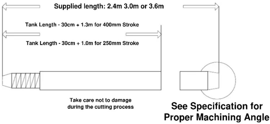
6.4.3 Assembling the Sonar Dome, Shaft and Tank Guide Assembly
After you have prepped the tank flange and shaft length, the next step will be to assemble the shaft to the dome unit.
- Coat the threaded area of the shaft; use the "Loctite" Nickel Anti-Seize supplied with the installation kit
- Coat the end of the shaft with DC 55 O-Ring lubricant
• Install the shaft lock nut (screw in all the way)
• Pass the dome cable through the shaft
• Fully screw the main shaft into the dome neck
Warning: Do not use a pipe wrench on the shaft (Just hand tight)
- Unscrew the lock nut until it makes contact with the neck of the dome. Use two 60mm wrenches, one on the neck of the sonar dome and the second on the lock nut, to tighten the two parts together; you will automatically lock the sonar dome to the shaft. Do not over tighten the lock nut to the sonar dome assembly
- Apply a coat of Loctite, Nickel Anti-Seize to the shaft in the area where the tank guide will be installed
- Securely fasten the tank guide as close as possible to the lock nut with the supplied hex bolts, spring washers. Ensure that the mounting bolts on the tank guide are facing the bow (forward)
Note: Apply Loctite, Nickel Anti-Seize to the threads of the hex bolts before assembling
• Install the Zinc anode on the flange
- Apply a thin coat of lubricant to the shaft, then pass the sonar dome cable through the bottom flange, following up through the main shaft. Great care must be taken when inserting the shaft in order not to damage the shaft scraper and O-Ring
- Insert the shaft packing, cut at a 45 degree angle and spaced 120 degrees apart. See drawing for details
- Slide the shaft-packing retainer over the top of the shaft and secure with the supplied mounting hex bolts and spring washers. Hand-tighten the shaft-packing retainer at this time; final adjustment should be made prior to the seatrial
- Slide the V Guide Heading Alignment Block from the top of the shaft and temporarily position it close to the packing retainer assembly; align the dome heading bow mark with the V Guide located on the flange (See Bow Mark located on the top of the sonar dome)
- Lock the V Guide Heading Alignment Block in the proper location using the supplied hex. bolts, spring washers; apply Loctite, Nickel anti-seize to the thread of the hex bolts before assembling
Sonar Dome, Shaft and Tank Guide Assembly

See Part 8 “Attachments and Drawings” for detailed assembly drawings.
6.4.4 Mounting the Flange and Sonar Dome to the Tank (Trunk)
Before lowering the sonar dome and flange assembly in position:
- Clean the top of the tank flange to remove any grease or rust buildup
- Apply a coat of "Loctite 2", gasket sealant supplied with the system
- Position the flange gasket and apply a coat of "Loctite 2" gasket sealant to the top of the gasket; lower the flange and sonar dome assembly into the retraction
tank, taking care not to damage the sonar dome
- Attach the tank flange assembly to the retraction tank using the supplied hex bolts, flat washers, spring washers and nuts; do not over tighten the bolts, otherwise you will damage the flange gasket.
- Next, position the sonar dome into its final position, by adjusting the V Guide alignment block. Ensure that the sonar dome is fully retracted into the sonar tank
Note: Apply Loctite, Nickel Anti-Seize to the threads of the hex bolts before assembling.
- The main shaft bearing must be greased. Remove the Vent Cap located on the opposite side of the grease fitting. Using the supplied Shell “SRS 2000” water resistance grease, fill until the grease comes out from the vent; re-install the Vent Cap.
See Part 8 “Attachments and Drawings” for detailed assembly information.
6.4.5 Mounting the Hoist Unit
A mounting pad is incorporated into the tank flange in order to secure the lower/raising ram assembly.
To secure the lower/raising assembly:
- Insert the clevis pin into position and secure in place by installing the hair-pin clip supplied with the system
- Install the Vent Cap on the oil reservoir, then manually raise the RAM unit by using the manual hand pump located on the hoist unit to its full "UP" position
- Slide the upper hoist retainer clamp from the top of the shaft into position
- Secure the upper part of the hoist unit in place using the clevis pin and hair-pin clip. Fix the upper shaft and hoist retainer clamp using the supplied hex bolts, flat washers and lock nuts; apply Loctite Nickel Anti-Seize to the threads of the hex bolts and the shaft before assembling
- Next, mount the Ram Alignment Guide on the Ram hoist unit; additional care must be taken to properly align the hoist unit
• Install the cable gland on the top of the shaft
See Part 8 “Attachments and Drawings” for detailed assembly information.
6.4.6 Mounting the Transceiver
Mounting pads are incorporated into the tank flange in order to secure the transceiver unit to the tank flange assembly. Secure the transceiver to the flange using the supplied hex bolts, flat washers, spring washers and nuts. Apply Loctite Nickel anti-seize to the threads of the hex bolts before assembling.
See Part 8 “Attachments and Drawings” for detailed assembly information.
6.5 INTERCONNECTION WIRING DIAGRAM
The interconnection wiring diagram for the transceiver unit, hoist unit, hull unit to the operating panel and interface unit are supplied in Part 8 “Attachments and Drawings”.
Note: An interconnection drawing is fixed on the inside cover of the transceiver unit.
6.5.1 Motion Sensor Electrical Connection
The interconnection of the transceiver to the motion sensor is supplied with external pre-wired connectors.
6.6 SL 30 OR SL 35 SYSTEM START-UP AND TEST
Initial power-up, set-up and testing of the system should be made with the vessel tied to the dock. Ensure there is sufficient water below the keel before you lower the sonar dome in order not to damage the hull unit.
6.6.1 SL 30/35 Start Up
Check that the system has been properly installed and that all connections have been made to the operating panel/interface unit, the processing unit and hull unit.
- Turn ON the power by pressing the power button located on the operating panel
- Next, turn ON the display monitor, and then turn ON the HP/PC; the system will
start up automatically. A green LED will light up indicating that power has been applied and no Alarms have been detected
- Next, press the Down Transducer Arrow button to lower the sonar dome into its position. The middle yellow LED will blink while the sonar dome is lowering. The lower green LED will light and remain illuminated when the sonar dome has reached the full down position
- Next, go to the Paragraph 6.6.4 "Run UP" procedure.
Note: If the SL 30/35 processing unit or the control / interface unit were replaced after the initial installation, you will have to re-do the "Power UP Configuration" located in the next Paragraph 6.6.2
6.6.2 Power-Up Configuration
For the system to operate properly, the SL 30 or SL 35 configuration must be selected correctly. In addition, modification of these power-up configuration parameters is done in a special mode selected after the power-up of the processor unit.
The following sections describe the process of configuring these parameters. These steps must be followed only when the system is powered-up for the first time or when you have to replace the processing unit or the interface unit assembly.
6.6.3 SL 30 or SL 35 Start up Procedure
For the purpose and demonstration on the Start-up Procedure in this chapter, we are using an HP/PC processing unit that has a COM 1 and a COM 2 port, Dual SVGA monitor output, Sound card and one Network LAN port. We will be using a dual sonar System, one SL 35, 90kHz sonar and one SL 30, 160kHz Sonar dome with motion sensors
The first step after a successful power up is to configure the system for the desired "User Setting" operating mode and set-up, if not already done; you will automatically select "Generic". Clicking on "Generic" or clicking on specific Users or types of fishery.
Refer to the following window.

Configuring the System for the first time, or if you have replaced the processing unit or the interface unit, you will select and "Click" on "Generic" and then "Click" on OK.
The next Window will pop up.

Go to the header menu:
- "Click" on "Configuration"
• a dialogue window will pop up - "Click" on "Connect Heads"
The following window will pop up.

After the "System Configuration" Window pops up, note that COM 1 and COM 2 have not been enabled (If no red check mark beside COM 1 and/or COM 2). If you "Click" on "Detect Heads" from this position, the following warning window will pop up.

This warning window indicates that "No Ports have been enabled"; just "Click" "OK".
The “System Configuration” window will reappear. Use the mouse to highlight the specific COM port. Note that the COM 1 and COM 2 Configuration will now be displayed. Use the mouse to “Enable for Head Control” (Left button click, check mark in box to enable).
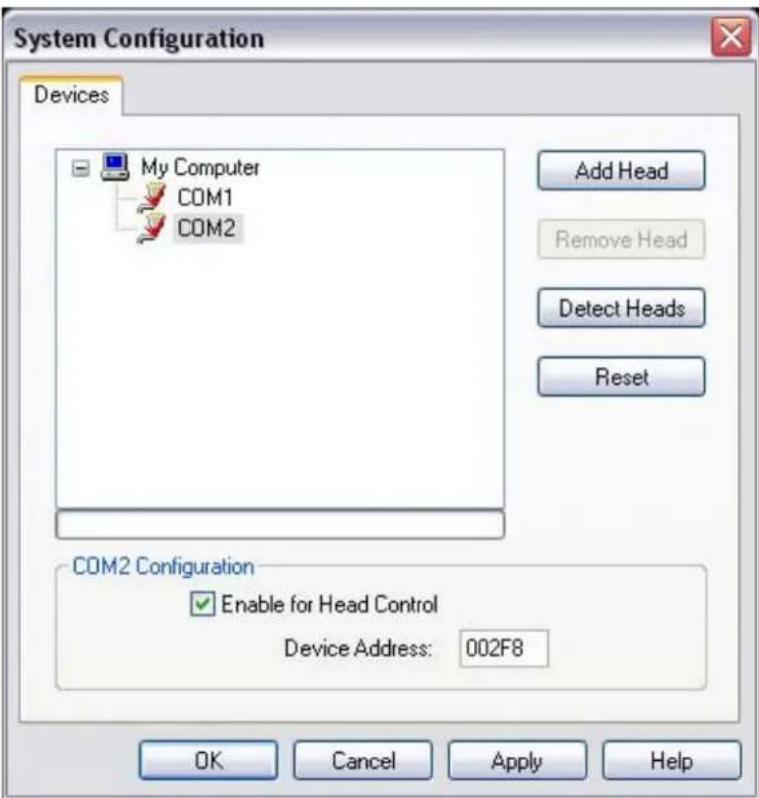
"Click" on "Apply". The following window may appear, overlaying the above window, asking you to reboot the computer. Just "Click" "OK". The window will disappear and do not "Reboot the computer now"; "Click" "OK" in the "System Configuration" window.

Now you will have to go to the Header Menu, "Click" on "Configuration" and a dialogue window will pop up. "Click" on "Connect Heads".
The "System Configuration" window will pop up. "Click" on "Detect Heads".
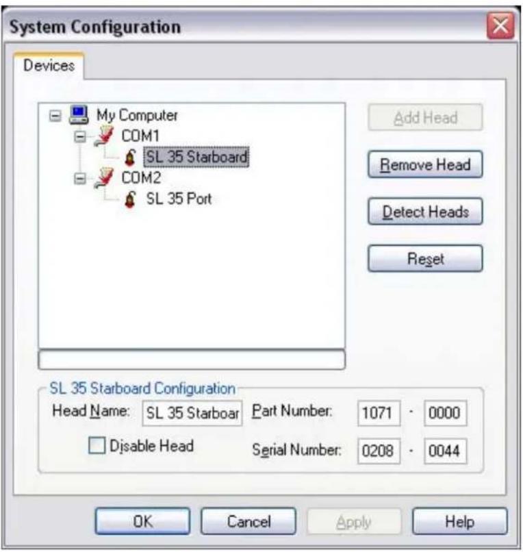
"Click" on "Apply", then "Click" "OK". From the Operating System window, "Click" on the "RUN" Icon to start the System.
In the event that part of the system gets changed out with a new component (i.e. a different interface unit, a change in software, etc), you might find that the Sonar Head Confirmation window might appear. It will ask you if you want to reconfigure "Click" on "NO", then go back to the "Header Menu" "Click" on "Configuration" and re-start the system set-up as per outline in Paragraph "6.6.3".

6.6.4 SL 30/35 RUN UP Procedure
After you "Click" on the "RUN" Icon, the system will automatically detect and setup the sonar. This operation will take approximately 40 sec.
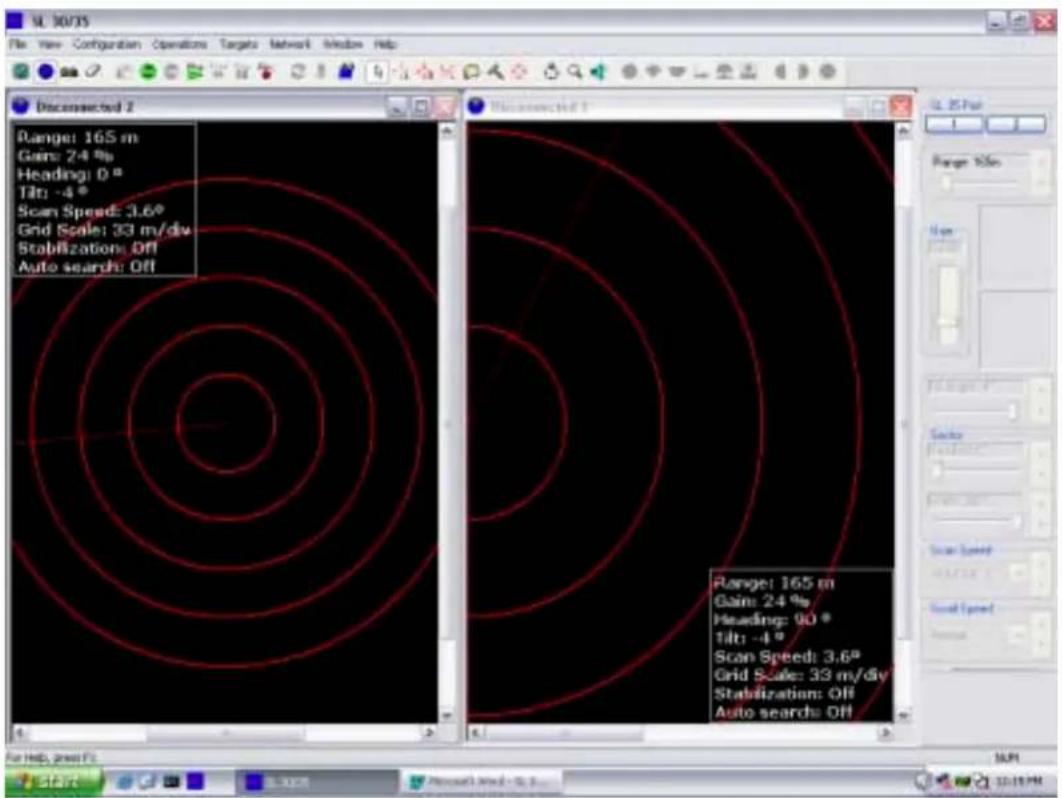
Refer to the following window
6.6.5 Display Settings
![Display Settings - Disconnected 2 Colors Controls Readout Options Primary Overlay Colors Sector Limit Profile Points Grid Cursor 1 Cursor 2 Annotation Colors on Second Head Sector Limit Profile Points Palette Style: Simrad [2] Load Customize Set Max Color Palette Threshold ( 0 ) OK Cancel Apply Help](/content/2026/05/868320/images/9eb0160227cce1748a258958b2aa2366a475579bce0b78349a831b189b5f0cc5.jpg)
By clicking on the appropriate "key", you will be able to change the color (i.e. Overlay colors, Palette styles and threshold, etc.).
6.6.6 Control Setting
By selecting and clicking on the "Control" key on the above window, the following window will pop up.

By clicking on the appropriate key, you will be able to setup your control settings, (i.e. gain control, RX gain, scan maker, etc.).
Note: The "Timer Control" will be turn "ON" automatically when you Click on the "CLOCK" Icon located on the "Tool Bar".
6.6.7 Readout Options
By selecting and clicking on the "Readout Options" key on the above window, the following window will pop up.

By clicking on the appropriate key, you will be able to setup your Readout Options, (i.e. Latitude, Longitude, Heading, Rang bearing, etc.).
6.6.8 SL 30/35 Settings
Position the cursor on the "CONTROL HEAD" key, (The one with the small sonar head located on the TOOL BAR) and CLICK. The following window below will pop up.
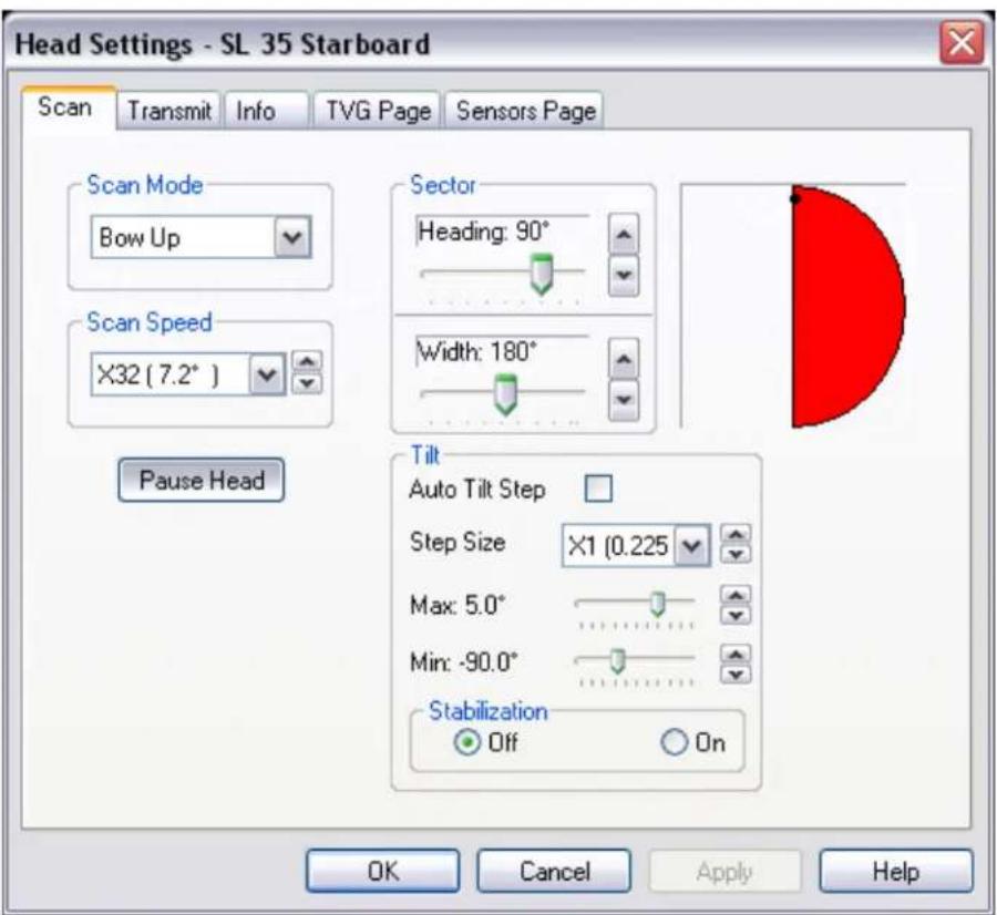
By clicking on the appropriate "KEY", you will be able to setup your Scan option. You also have full control of the Scan mode via the operator control panel.
6.6.9 Transmit Setting Page
By selecting and clicking on the "Transmit" key on the above window, the following window will pop up.

By clicking on the appropriate key, you will be able to setup your Transmitter configuration in order to optimize fish detection.
6.6.10 TVG Setting Page
By selecting and clicking on the "TVG Page" key on the above window, the following window will pop up.

By clicking on the appropriate key, you will be able to setup your TVG setting. You also have the option of customizing your TVG setting for a specific fishery.
6.6.11 Info Page
By selecting and clicking on the "INFO" key on the above window, the following window will pop up.

This INFO page will provide you with all the relevant information on the sonar head attached to the system.
6.6.12 Sensor Page
By Clicking on the "SENSOR PAGE" key on the above window, the following window will pop up.
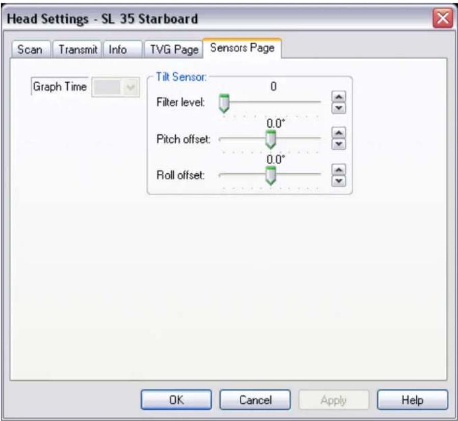
After you have installed the Pitch and Roll Motion Sensor in a +/- 5 degrees in bought axis.
- Adjust the Filter to "7".
- Adjust the Pitch and the Roll offset by the error indicated on the sensor window.
- Next Click on "Apply" then Click on "OK".
6.6.13 User Setting
After you have completed your system configuration, you should save your settings, Go to the Header Menu and Click on "Configuration". Next Click on "USERS", then Click on "DEFINE", The following window will pop up.
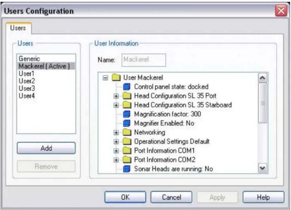
The next step, if you want to Add a User, Click on "Add", then type the name in the User Information "Name" (for example type "Herring") in the window. Next Click on "Apply" then "OK".
The next time you start up the system, the "Select User" window will pop up automatically; you must select the type of Fishery or User settings you want to run and "Click". The system will start up with your personal setting or select your User 1 setting.
When you "Exit" the system, the system will request if you want to save your setting. Just say "YES" or "NO"
Note: After the Service Engineer has completed the initial Setup and Seatrial, we recommend that all the settings be saved in the "USER 1" setting or in a specific file created as a reference in case a problem occurs. If you have a problem, just go back and select the "GENERIC" setting, or to your specific file for the seatrial.
6.6.14 Save Additional User Operation or Specific Fishery Setting
After you have completed your system configuration and user setting and want to Add specific types of "Fishery" setting. Go to the Header Menu and "Click" on "Configuration". Next "Click" on "USERS", then "Click" on "DEFINE". The following window will pop up.

The next step, if you want to Add a User, "Click on "Add", then type the name in the "User Information" window. Next "Click" on "Apply" then "Click" on "OK"
The next time you start up the system, the "Select User" window will pop up automatically; you must select the type of Fishery or User setting you want to run and "Click" "OK".
When you Exit the System from the "File" Header Menu, the system will request "Are you sure you want to exit?" "Click" on "Yes". Then the System will request "Do you want to save settings?" "Click" on "Yes" if it is new settings or "No" as you prefer.
6.7 USER 1, 2, 3, 4 SETTINGS
The pre-defined USER settings will be explained in Part 5, "Selecting Settings":
Note:
The “GENERIC” (factory settings) setting is overwrite protected and can not be changed in the field.
6.8 AUDIO AND POST PROCESSING SET-UP
6.8.1 Post Processing

By Clicking on "Operations" the above dialog window will pop-up; click on "Post Processing", the following dialog window will pop-up.

By Clicking on "Enable Image Smoothing" you will activate or de-activate the Smoothing of the sonar picture. By sliding the "Minimum Step", you will control the smoothing effect.
By Clicking on "Enable Filter" you will activate or de-activate the Acoustic Filter of the sonar. By sliding the "Threshold (100)", you will control the filtering effect. The "Acoustic Interference" is also referred to as a "Ping to Ping" filter.
6.8.2 Audio Set-up

By Clicking on "Configuration" the above dialog window will pop-up, then Click on "Audio Set-Up", the following dialog window will pop-up.
Note: You must activate the "Audio" by clicking on the "Audio" Icon, prior to clicking on "Configuration" If you do not activate the "Audio", you will not be able to set-up your Audio parameter.

By selecting the appropriate dialog box, you will be able to change the Sound Duration, control the Noise Threshold, the Audio Frequency Min. Max "Range" of the target and the start "Close" and "Long" start of the Audio.
Note: The Range Threshold in a “%” on the operating range of the sonar.
PART 7
TROUBLESHOOTING AND MAINTENANCE
7. TROUBLESHOOTING AND MAINTENANCE....7.3
7.1 INTRODUCTIONS....7.3
7.2 SYSTEM OVERVIEW....7.3
7.3 HANDLING & MAINTENANCE 7.3
7.3.1 Wheelhouse Electronics 7.3
7.3.2 Hull Unit 7.3
7.4 PREVENTIVE MAINTENANCE....7.4
7.4.1 Lubrication (SL 35 Only) 7.4
7.4.2 Manually Raising Sonar Dome (SL 35 Only)....7.4
7.4.3 Lower and Raise unit (SL 35 Only) 7.5
7.4.4 Tank Flange shaft Bearing, Seals and Sonar Dome (SL 35 Only) .....7.5
7.4.5 SL 35 Shaft and SL30/35 Sonar Dome Damage....7.5
7.4.6 Corrosion....7.5
7.5 TROUBLESHOOTING....7.6
7.6 ERROR MESSAGES LOG....7.6
7. TROUBLESHOOTING AND MAINTENANCE
7.1 INTRODUCTIONS
This document is intended to provide a minimum level of instructions for the proper handling, maintenance and troubleshooting of the SL 35 Hull Sonar.
7.2 SYSTEM OVERVIEW
The Simrad SL 30/35 Hull Sonar consists of the wheelhouse electronics and the hull unit assembly. The wheelhouse electronics include the LCD display, the SL 30/35 processing unit and the operator panel with the integrated interface unit.
The hull unit consists of the sonar dome unit, the lower/raise unit and the transceiver unit. An optional pitch and roll sensor is also available.
7.3 HANDLING & MAINTENANCE
The most common cause of failure is poor preventive maintenance. Proper handling and maintenance can significantly reduce the frequency of failures.
The following sections outline the recommended handling and maintenance for the SL 30/35 Hull Sonar.
7.3.1 Wheelhouse Electronics
Once installed, these units require little maintenance other than removing dust. A damp, lint-free cloth should be used for this purpose.
Note: It is absolutely essential that these units receive proper ventilation, particularly if the boat is operating in warm climate locations.
7.3.2 Hull Unit
The hull unit is subjected to the harshest conditions, and therefore proper maintenance is crucial to ensure trouble free operation.
7.4 PREVENTIVE MAINTENANCE
The following items should be checked as part of routine maintenance on a monthly basis:
- Check all cables; replace if damaged
- Check all connectors at the rear of each unit; clean, if necessary, and replace if damaged
- Check all ground connections for each unit; clean, if necessary, and replace if corroded
- Check supply voltage to ensure it is within the equipment power rating
7.4.1 Lubrication (SL 35 Only)
Grease the lower and raise main shaft bearing twice a year, using Shell “SRS 2000” water resistance grease. A grease fitting is installed on the tank flange to facilitate the greasing. Note that a “VENT” plug located on the opposite side must be removed prior to applying the grease. If the “VENT” plug is not removed, you will damage the O-Ring and shaft seals.
See Part 8 "Attachments and Drawings" for the grease fitting location.
7.4.2 Manually Raising Sonar Dome (SL 35 Only)
The manual pump should be tested twice a year, to ensure proper operation as follows:
- First, lower the sonar dome via the operator panel
- Check that the sonar dome is fully lowered
- Next, turn ON/OFF the power switch located on the transceiver unit to the OFF position
- Manually activate the hand pump until the sonar dome is totally retracted into the ship hull.
- If the sonar dome cannot be raised smoothly, do not use excessive force; the shaft may be bent and will cause damage to other components.
- Next, turn the power switch to ON, the sonar dome will automatically be lowered.
7.4.3 Lower and Raise unit (SL 35 Only)
For the SL 35 only, once a month, check the lower and raise ram unit for oil leakage; if a small amount of oil is present, clean and monitor on a regular basis. Check the oil level and top up using Standard Automatic Transmission oil. Do not over-fill the reservoir; re-install the vent cap.
7.4.4 Tank Flange shaft Bearing, Seals and Sonar Dome (SL 35 Only)
When the ship is dry-docked, remove the sonar dome assembly, clean and remove marine growth from the dome with a fine scraper or a piece of wood.
- Check the tank guide assembly; replace if damaged or worn-out
- Remove the tank flange and disassemble the main shaft bearing and seals and re-build using a special kit that contains all seals, shaft scraper and a new zinc anode
- Using the oil level gauge supplied in the installation kit, remove one of the oil plugs located on the top of the sonar dome and insert the gage and insure that the oil level is ok. If not, top up to the proper mark on the oil gage using Shell Tellus 15.
Note: Do not over fill the sonar dome, space must be allowed for expansion and contraction due to water temperature changes.
See Part 8 "Attachment and Drawings" for detailed procedure.
7.4.5 SL 35 Shaft and SL30/35 Sonar Dome Damage
The sonar dome and shaft should be inspected for damage. If the sonar dome has experienced an impact, this could bend the shaft and eventually allow water into the soundome unit.
7.4.6 Corrosion
If, on examination, corrosion has occurred to the sonar dome, replace the damaged parts. If corrosion has occurred on the flange assembly, clean the area and seal with paint to prevent continuation of the corrosion in this area.
7.5 TROUBLESHOOTING
The SL 30/35 was designed to be a trouble free system. The table below provides some common symptoms of failure and means to rectify them.
- Cannot turn the power ON
- Check ship main power input
- Check cable between interface unit and transceiver
- Have a qualified service engineer check the system
- Irregular bottom echo's
- Distance to the bottom changes due to pitching and rolling. "Rough seas".
- Long range selected and transmission period has changed
- Weak Echoes
• Output power set to low
• Excessive RCG/AGC
- Pulse length not set properly
- Noise on the Screen
• Bad grounding of the units
- RCG not set properly
• Sea surface contains debris
- Rough seas
7.6 ERROR MESSAGES LOG
An error messages log file is automatically generated to assist in troubleshooting the system; Refer to Part 4 "System Message Log" for additional information.
PART 8
ATTACHMENTS AND DRAWINGS
8. ATTACHMENTS AND DRAWINGS.... 8.3
8.1 LIST OF ATTACHMENTS 8.3
8.2 LIST OF DRAWINGS 8.3
8. ATTACHMENTS AND DRAWINGS
8.1 LIST OF ATTACHMENTS
| Drawing Number Description |
| 901-10111802 SL 30/35 Surface Processor Software Set-up |
8.2 LIST OF DRAWINGS
| Drawing Number | Description |
| 359-00888000 | Fabrication Drawing - 8” Retraction Tank SL35 Hull Unit |
| 363-01228000 | Shaft – Hull Mount |
| 422-40561001 | Outline & Installation Drawing - HMS Transceiver Box |
| 808-00101001 | Outline Drawing - Hydraulic Actuator 250mm/400mm Stroke SL35 Hull Unit |
| 901-60101001 | Outline & Installation Drawing - SL35 User Interface - HMS |
| 901-60121000 | Assembly Drawing – SL30 User Interface Box |
| 901-60121002 | Wiring Installation Drawing – S30 User Interface Box |
| 901-60121003 | Wiring Drawing – SL30 User Interface Box |
| 901-60131000 | Assembly Drawing – SL30 Power/Telemetry Box |
| 901-60131002 | Wiring Installation Drawing – SL30 Power/Telemetry Box |
| 901-60131003 | Wiring Drawing – SL30 Power/Telemetry Box |
| 974-25181001 | Installation Drawing – Steel/Aluminum Hull SL30 Hull Unit |
| 974-25181002 | Installation Drawing - Fiberglass Hull SL30 Hull Unit |
| 974-35001003 | Wiring Diagram - HMS Transceiver Box |
| 974-35051000 | Assembly Drawing – SL30 Transceiver Box |
| 974-35051002 | Wiring Installation Drawing – SL30 Transceiver Box |
| 974-35051003 | Wiring Diagram – SL30 Transceiver Box |
| 974-25001001 | General Arrangement – SL35 Hull Unit |
SL 30/35 Hull Sonar Surface Processor Setup Instructions
Document Number: 901-10111802 (Issue 1.4)
LIST OF CONTENTS
SL 30/35 HULL SONAR SURFACE PROCESSOR SETUP INSTRUCTIONS....2
1 SET UP WINDOWS XP/2000 OPERATING SYSTEM 2
2 SETUP THE BOOT TIME 4
3 SETUP THE REGISTRY FOR AUTOMATIC LOGON....4
4 INSTALL THE SL 30/35 HULL SONAR SOFTWARE .... 5
5 SETUP THE STARTUP FOR AUTOMATIC SL 30/35 EXECUTION....6
6 SETUP THE NETWORKING 6
SL 30/35 HULL SONAR SURFACE PROCESSOR SETUP INSTRUCTIONS
1.1. Make a note of the computer serial number printed on the label on the top of the computer.
1.2. Turn on the computer.
- Windows XP
1.3. The "Welcome to Microsoft Windows XP" screen will appear, press "Next".
1.4. Use default selections on the next "Select System Settings" screen, push "Next".
1.5. Leave the default selection “(GMT) Greenwich Mean Time” on the “Time zone selection” screen, push “Next”.
1.6. The "End User License Agreement" will appear, select "Yes" and press "Next".
1.7. When the installation procedure asks you to enter a name for the computer, type in "SL3035-" followed the serial number without the first three letters "US0". For example, if the serial number is US01274363, then enter the name "SL3035-1274363", push "Next".
1.8. On the next screen "How will this computer connect to the Internet?" select "Local Area Network (LAN)", then press "Next".
1.9. "Setting up a high speed connection" will appear, select "Obtain IP address automatically" and "Obtain DNS automatically", press "Next".
1.10. On the next screen "Ready to register with Microsoft?" select "No", push "Next".
1.11. On "Thank you" screen push "Finish", the computer will restart.
1.12. After reboot Windows starts "Found new hardware wizard" to install a driver for an additional serial ports board. Insert a floppy disk labelled "PCI Drivers Disk for Windows" into the floppy disk drive.
1.13. Select "Install from a list or specific location", click "Next".
1.14. Click "Include this location in the search", enable "Search Removable Media".
1.15. Click "Browse", then "My Computer", select "3 12 Floppy (A)", press "Next".
1.16. Click "Continue Anyway", press "Finish".
1.17. "Found new hardware wizard" pops up again to install a video card driver, insert a CD-ROM with Nvidia drivers; select "Install from a list or specific location" and push "Next".
1.18. On the screen "Please choose your search and installation options" go with the default selections: "Search for the best driver in these locations" and "Search removable media", press "Next".
1.19. Windows will find and install drivers for the video card; when it completes the installation, the wizard should say: "The wizard has finished installing software", press "Finish".
1.20. Follow "Found new hardware wizard" for port "A" by selecting "Install from a list or specific location", click "Next" and press "Next" again on the next dialog.
1.21. Click "Continue Anyway" and push "Finish" to close the wizard.
1.22. Repeat 1.20 and 1.21 for port "B".
Windows XP Service Pack Installation
1.23. Insert the SL 30/35 installation CD-ROM in the CD drive, right-click the "Start" button and
select "Explore".
1.24. Click on the CD drive in the left pane of the Windows Explorer and open the directory "ServicePack / WinXP".
1.25. Run the program "xpsp1a_en_x86.exe" by double clicking it.
1.26. The program validates the installation package, then unpacks all its components and greets you with Welcome screen, press "Next" to proceed.
1.27. The "License Agreement" screen will appear, select "I Agree" and push "Next".
1.28. On the next screen select "Do not archive files" and push "Next".
1.29. The program will show a dialog saying "Updating your system …", when it is done, press OK to reboot the computer.
1.30. When the computer reboots, right-click on the "Start" button and select "Properties", on the "Start Menu" page select "Classic Start Menu" and press OK, you should see "My Computer" and other icons on the Desktop now.
1.31. Right-click on the Desktop and select "Properties", on the "Appearance" page from "Windows and Buttons" drop-down list box select "Windows Classic Style". On the "Screen Saver" page select "(None)" from the "Screen saver" list. Press "OK".
1.32. Click on the "Start" button and select "Settings->Control Panel". Click "Switch to classic view" in the top left corner, then double-click "Power Options" icon, make sure that the settings are as follows: "Power Schemes" page – select "Never" in each of the following drop-down list boxes: "Turn off monitor", "Turn off hard disks" and "System standby"; "Hibernate" page – "Enable hibernation" is not selected. Push OK to apply the changes.
1.33. Double-click on "System" icon in "Control Panel", open "Advanced" page by clicking on its tab, and then open "Performance Options" dialog by pushing "Performance Setting" button. In the "Performance Options" dialog select "Adjust for best performance", push OK to apply the change and then on the "System Properties" press OK again to dismiss the dialog.
1.34. Right-click on the Taskbar, select Properties, check "Auto-hide the taskbar" check box and push "OK".
- Windows 2000
1.3. Note the computer serial number printed on the label at the back of the computer.
1.4. Turn on the computer. The "Working In Comfort" screen will appear. From the "File" menu, select "Exit" to close this screen. The computer will initiate the setup procedure.
1.5. When the installation procedure asks you to enter a name for the computer, type in "SL3035" followed by the serial number without the first three letters "US0". For example, if the serial number is US01274363, then enter the name "SL3035-1274363". Leave the "Administrator Password" and "Confirm Password" boxes empty and push the "Next" button. The system will continue the setup procedure.
1.6. After a period of time, the "Completing the Windows 2000 Setup Wizard" window appears. Press "Finish". The system will continue the setup and eventually reboot itself.
1.7. After a period of time, the "Log on to Windows" dialog box will appear, asking you to enter the Password for the Administrator. Do not type anything there and just press the "OK" button to proceed.
1.8. The "Getting started with Windows 2000" window will appear. Uncheck the "Show this screen at startup", located at the bottom left of the window and press "Exit". The window should disappear.
1.9. Right click the mouse in the center of the screen where there are no Icons and select "Properties" from the popup menu.
SL 30/35 Hull Sonar Surface Processor Setup Instructions 901-10111802 / Issue 1.4
Page 4
1.10. From the "Background" page, select "None" from the list of background pictures that can be displayed on the screen. The "None" selection is at the top of the list. Click on "Apply", then "OK" and you will return to the Desktop.
2 SETUP THE BOOT TIME
- Windows XP
Nothing needs to be done here.
- Windows 2000
2.1. Right-click on the Icon "My Computer" in the desktop and select "Properties". The "System Properties" dialog box should appear.
2.2. Select the “Advanced” page and press the “Startup and Recovery” button. The “Startup and Recovery” dialog box should appear.
2.3. In the "System Startup" group, reduce the "Display list of operating systems for" value to 1 second and press "OK".
2.4. Press "OK" to close the dialog box.
3 SETUP THE REGISTRY FOR AUTOMATIC LOGON
- Windows XP
Nothing needs to be done here.
- Windows 2000
3.1. Click the Start button on the task bar located on the lower left corner of the screen.
3.2. Select "Run" and type in "regedit" in the "Open" selection area and press "OK". You should see Registry Editor application that is very similar to the Explorer.
3.3. Expand the "HKEY_LOCAL_MACHINE" key by clicking on the "+" sign.
3.4. Expand the "Software" key.
3.5. Expand the "Microsoft" key.
3.6. Expand the "WindowsNT" key.
3.7. Expand the "CurrentVersion" key.
3.8. Click on the "Winlogon" key. You should see a list of items on the right side of the screen.
3.9. In the "Edit" menu, select "New->String Value."
3.10. Type the name AutoAdminLogon and press "Enter" on the keyboard.
3.11. Double click on the "AutoAdminLogon" in the right side under the Name column. The "Edit String" dialog box should appear. Type in 1 for the value data and press "OK" to close the dialog box.
3.12. From the "Registry" menu, select "Exit" to close the Registry Editor.
3.13. Insert the SL 30/35 installation CD in the drive (label up).
3.14. Right click the "Start" button on the task bar and select "Explorer".
3.15. Click on the CD drive and select the directory "ServicePack/Win2000".
3.16. Run the program "W2KSP4_EN.EXE" by double clicking it.
3.17. The program starts to load all its necessary components first and then pops up the license agreement dialog box. Enable the “Accept the license agreement…” button, click “Install” and follow the instructions. This could take about 5 minutes.
3.18. At the end of the installation, the system tells you to restart the computer. "Restart".
3.19. Once the system is up and running again, if the Explorer is closed, then right click on the "Start" button and select Explorer again.
3.20. Click on the CD drive and select the "Matrox Display Driver" directory. Run the program
SL 30/35 Hull Sonar Surface Processor Setup Instructions 901-10111802 / Issue 1.4 Page 5
"w2k_551.exe" on the right hand side of the Explorer by double clicking on it.
3.21. The "WinZip Self-Extractor" dialogue box should appear with "C:\mgafold\w2k_551" listed. Push the "Unzip" button. It should start extracting the files and display the "28 files unzipped" message. Press "OK" to get rid of the message box and then push "Close" to close the WinZip dialogue box.
3.22. Press the "F5" key on the keyboard to update the Explorer listing. You should see the subdirectory "mgafold" on the C drive (left hand side of the Explorer).
3.23. Double click on the "mgafold". You should now see the "w2k_551" subdirectory. Click on the "w2k_551" directory and look for the program "Setup.exe" on the right hand side of the Explorer. Run the "Setup" by double clicking it. "Matrox Power Desk" dialogue box should appear.
3.24. Push "Next" for language selection (English).
3.25. Push "Next" for devices supported (Matrox Millennium G400 Dual Head).
3.26. Click on the check box beside the "Dual Head Multi Display..." to select that option and push "Next".
3.27. Do not put a check beside the "Performance Settings" and "Power Desk Feature Settings". Just press the "Next" button.
3.28. Continue by pressing "Next" to accept all the settings. It will load some files. Every time the setup displays the dialogue box "Digital Signature Not Found", just press "Yes" to continue.
3.29. Press “Next” to finish the setup and press “Finish” to reboot the computer. After the reboot, the system will come up with the “Log On To Windows” dialogue box. Just press “OK” without entering a password.
3.30. If the Explorer comes up again, close it by selecting the "Close" entry in the "File" Menu.
3.31. If the "Matrox Online Registration" dialogue box is still active, click in the check box beside "Do not show this message again" and then press "Don't register". Press "OK" on the next dialogue box to exit setup.
4 INSTALL THE SL 30/35 HULL SONAR SOFTWARE
4.1. Insert the SL 30/35 installation CD in the drive (label up).
4.2. Click the Start button on the task bar located on the lower left corner of the screen.
4.3. Select "Run". You should see "Run" dialog box.
4.4. Press the "Browse" button. The "Browse" dialog box should appear.
4.5. Press the drop down arrow in the "Look in:" section at the top of the dialog box and select the CD drive. You should see the "Sample Data", "SL3035-Win9xMe" and "SL3035-Win2000XP" subdirectories.
4.6. Double click on "SL3035-Win2000XP". You should see "Isdel.exe" and "Setup.exe".
4.7. Double click on "Setup.exe". The browse dialog box should automatically close and the name and the full path of the setup file should appear.
4.8. Press "OK" to close the Run dialog box. The SL 30/35 setup screen should appear.
4.9. Press the "Next" button for the rest of the dialog boxes that appear during the setup.
4.10. When the "Setup Complete" dialog box appears, select the "No, I will restart my computer later" option by clicking on it.
4.11. Press the "Finish" button for the next two dialog boxes.
4.12. The setup is now complete and you should be able to see the SL30-35 Icon on the desktop.
4.13. Run the SL30-35 by double clicking on its Icon on the desktop.
4.14. If the "Select User" dialog box appears, click on the "Generic" and press OK.
4.15. From the "Configuration" menu, select the "Connect Sonar...". The "System Configuration" dialog box should appear.
4.16. Click on "COM1" and then click in the little box on the left-hand side of the "Enable for Head
SL 30/35 Hull Sonar Surface Processor Setup Instructions 901-10111802 / Issue 1.4 Page 6
Control". A red check mark should appear on COM1.
4.17. Repeat the above for COM3. Type in 01080 into the edit box next to "Device Address:" .
4.18. Repeat 4.17 for COM4. Type in 01088 into the edit box next to "Device Address".
4.19. Press "OK" to close the dialog box. The program will inform you that you should reboot the computer. Just click "OK" in response.
4.20. Select "Exit" from the File menu to close the SL 30/35 application. Answer "Yes" to all the questions asked. When the "Select User Configuration" dialog box appears, click on "Generic", press the letters Q and W on the keyboard and while holding them down, click "OK". Note: Do not change any preset settings in the "Generic" User File.
4.21. Remove the Installation CD from the drive.
5 SETUP THE STARTUP FOR AUTOMATIC SL 30/35 EXECUTION
5.1. Right-click on the SL 30/35 Icon on the desktop and select "Copy".
- Windows XP
5.2. Right-click on the "Start" button in the taskbar and select "Explore".
5.3. Expand the "Programs" folder by clicking on "+" next to it in the left pane.
5.4. Select the "Startup" folder by clicking on it in the left pane.
5.5. Right-click in the right pane and select "Paste", The SL30-35 icon should appear.
5.6. Exit the Explorer through the "File | Close" menu.
5.7. Follow the instructions for Windows 2000 section 5.9.
- Windows 2000
5.2. Click on the "Start" button in the taskbar and select "Settings->Taskbar". The taskbar properties dialog box should appear.
5.3. Select the "Advanced" page and press the "Advanced..." button.
5.4. Double click the "Programs" Icon.
5.5. Double click the "Startup" Icon.
5.6. From the "Edit" menu, select "Paste". The SL30-35 Icon should appear in the right side.
5.7. Exit the Explorer through the "File | Close" menu.
5.8. Press "OK" to close the taskbar Properties dialog box.
5.9. Click on the "Start" button on the taskbar and select "Shut Down". The shut down windows dialog box should appear.
5.10. Select the "Restart" option from the drop down list and press "OK". Computer should go through its shut down procedure and reboot into the SL30-35 application without requiring a logon. If the "Select User" dialog box appears, click on the "Generic" and press "OK".
6 SETUP THE NETWORKING
6.1. Push the "Start" button on your task bar and select "Run..." from the pop up menu.
- Windows XP
6.2. Type in "dcomcnfg" and press OK. "Component Services" "Explorer-style" dialog will appear. In the left pane click on the "+" next to "Component Services". When an hourglass disappears, click on "Component Services" itself, then click on the "+" next to "Computers", then on "+" next to "My Computer".
6.3. Expand "DCOM Config" folder by clicking on "+" next to it, then scroll down and find "SL30-35".
SL 30/35 Hull Sonar Surface Processor Setup Instructions 901-10111802 / Issue 1.4
6.4. Right-click on the "SL30-35" in the left pane and select properties, then follow the instructions for Windows 2000. In order to add a user, type in "Everyone" in the provided dialog and press "OK".
- Windows 2000
6.2. Type in "dcomcnfg" and press "OK". The Distributed COM Configuration Properties dialog box should appear. Select the Default Properties page and set it up as follows.
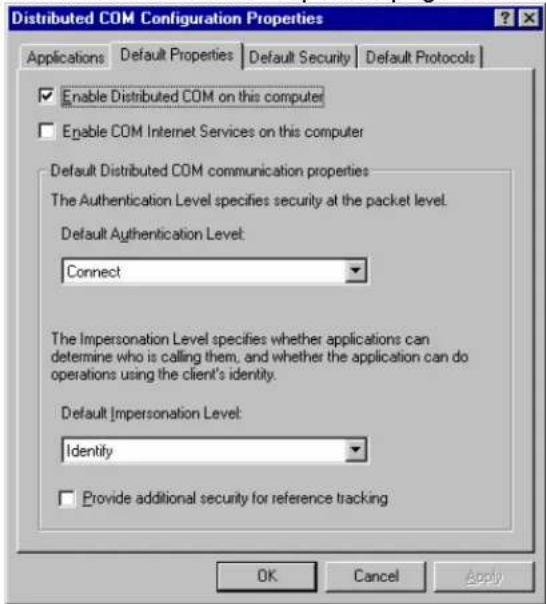
6.3. Go to Application page and select SL30-35 from the "Distributed COM Configuration Properties list of registered applications.
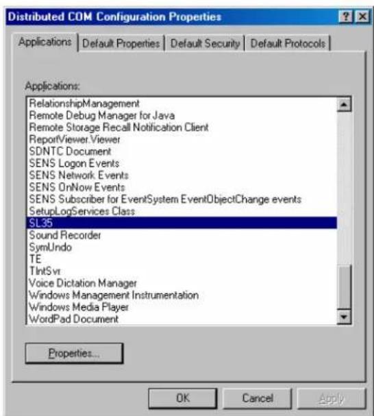
SL 30/35 Hull Sonar Surface Processor Setup Instructions 901-10111802 / Issue 1.4 Page 8
6.4. Press the "Properties..." button. The "SL30-35 Properties" dialog box should appear. Select the "Location" page and set it up as shown.
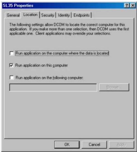
6.5. Go to the "Security" page and select "Use custom access permissions", "Use custom launch permissions" and "Use custom configuration permissions" options as shown.

Kongsberg Mesotech Ltd. Port Coquitlam, BC - Canada
SL 30/35 Hull Sonar Surface Processor Setup Instructions 901-10111802 / Issue 1.4 Page 9
6.6. Press "Edit..." button in "Use custom access permissions" to modify the permissions for that option. You should see the following dialog box for each one of them. If the text "Everyone" does not appear as shown bellow, then press the "Add" button.
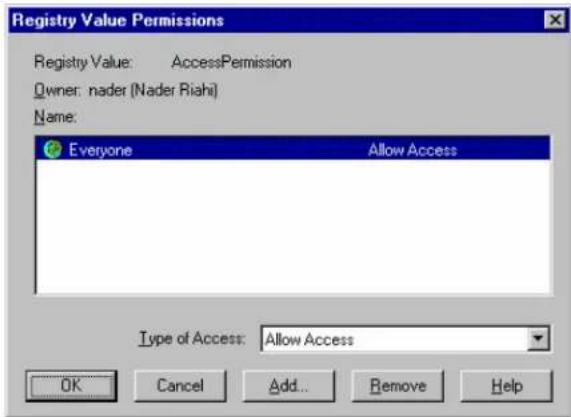
6.7. Pressing the "Add" button will pop up the "Add Users and Groups" dialog box as follows.

6.8. Select "Everyone" entry from the list of names and press the "Add" button. Press "OK" to accept the selection. You should now see "Everyone" in the "Registry Value Permissions" dialog box. Press "OK" to accept the change and close the dialog box.
6.9. Repeat steps 6.6 to 6.8 to set up the "Use custom launch permissions" and "Use custom configuration permissions" options.
6.10. You should be back to "SL30-35 Properties" dialog box at this stage. Go to the "Identity" page and set it up as shown below.
SL 30/35 Hull Sonar Surface Processor Setup Instructions 901-10111802 / Issue 1.4 Page 10

6.11. Press "OK" to accept the changes and close the dialog box. This will take you back to the "Distributed COM Configuration Properties" dialog box. Press "OK" one more time and you are done!
6.12. Click on the "Start" button on the taskbar and select "Shut Down". The shut down windows dialog box should appear.
6.13. Select the "Shut down" option by clicking on it and press "OK".
6.14. Connect the networking cable between this computer and another SL30-35 computer that already has the networking setup on it.
6.15. Switch both computers on and exit the SL30-35 application. Go to Explorer to see if both computers are listed under the "My Network PlacesComputers Near Me".
6.16. Run the SL30-35 on both computers.
6.17. Attach the dongle that has the networking option enabled to the computer with the sonar head(s) and a basic dongle to the computer without the sonar head(s).
6.18. In the SL30-35 system with sonar head(s), click on the Networking menu and select "Connect to Client". The following dialog box should appear
SL 30/35 Hull Sonar Surface Processor Setup Instructions 901-10111802 / Issue 1.4 Page 11
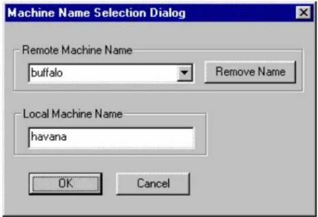
6.19. Enter the name of the SL30-35 computer without the sonar head(s) in the "Remote Machine Name" and the name of the SL30-35 computer with the sonar head(s) in the "Local Machine Name" and press "OK". Name designation procedure is the same as that described in Section 1, step 1.3 (e.g. SL3035-1274363).
6.20. The computer without the sonar head(s) should now also see the sonar images. If not, go back to the start of Section 6 (Setup the Networking), and make sure that the setup is correct.
6.21. Exit the SL30-35 systems on both machines. When the "Select User Configuration" dialog box appears, click on "Generic", press the letters S and G on the keyboard and while holding them down, click "OK". NOTE: Do not change any sonar settings.
6.22. Shut down the computers by selecting the "Shutdown" entry from the "Start" button on the task bar.
![45° Ø29/32 (230) & HOLES Ø Ø 0.02 (35.5) Ø1150 (297) Ø1ES: Ø8.62 [219] x 0.50 [12.5] TUBE, DIN 17121 SI 52.3N Ø 0.79 [30] PLATE: DIN 17107 SI 52 IN](/content/2026/05/868320/images/fb463f271a69dc9b21c359e7f28bbcded04c1b826575dc95bd84029918a7be40.jpg)
DWG NO 359-008880001 S/1 PS
![4 - X - φ7.52 17940 (φ8.62 2019) 0.01 [0.05] X 0.01 [0.05] 3 1 5 6 2 5 6 0.79 [20] 7](/content/2026/05/868320/images/a73a7c33bfefeeb3c4b1aa404b14ee573aa596836e37c8104fdab4e0fd029310.jpg)
NOTES:
1 #8.62 [219] × 0.50 [12.5] TUBE, DIN 17121 SI 52.3N
[2] 0.79 [20] PLATE, DIN 17100 St 52.3N
[3] ALL WELDS TO BE PERFORMED BY CERTIFIED WELDER IN ACCORDANCE
WITH DNV CLASSIFICATION RULES
4 ONV STAMP AND CHARGE NO.
5 SAND BLAST PER SSFC-SP10 [So 2.5]
6. APPLY PRIVER AND TOPCOAT SUITABLE FOR IMVERSION SERVICE
7 LENGTH TO BE DEFINED BY SHIPYARD - REFERENCE DWG. 974-2500:00
B CONSTRUCTION AND INSTALLATION TO BE APPROVED BY LOCAL
CLASSIFICATION AUTHORITY, BRACKETS OR OTHER REQUIRED SUPPORT
FOR THE RETRACTION TANK IS THE RESPONSIBILITY OF THE INSTALLING
SHIPYARD AND SHALL BE INSTALLED TO THE SATISFACTION OF THE DNV SURVEY
9 UNLESS OTHERWISE SPECIFIED. DIMENSIONS ARE IN INCHES [MILLIMETERS]
10 DO NOT SCALE
| PROPRIETARY NOTICE THIS DOCUMENT CONTAINS INFORMATION WHICH IS THE SOFT PROPERTY OF KONOSBERG SIMRAD MESOTECH LTD. AND IS RECEIVED IN CONFIDENCE. ITS CONTENTS MAY NOT BE DISCLOSED OR REPRODUCED IN ANY WAY WITHOUT THE WRITTEN CONSENT OF KONOSBERG SIMRAD MESOTECH LTD. | APPROVALS | DATE | Kongsberg Simrad Mesotech Ltd. | |||
| DRAWN | BNS | DWGS | ||||
| CHECKED | FABRICATION DRAWING - 8" RETRACTION TANK SL35 HULL UNIT | |||||
| ENQR | ||||||
| ISSUED | ||||||
| NEXT ASSY | MODEL | SIZE B | NOM NO 1C965 | TYPE MD | DWG NO. 359-00888000 | |
| ZONE | ||||||
| - | - | SCALE: 1/2 | W.O. NO. | SHEET 1 OF 1 | ||


| 1.1 | ECO 3417 | 02/09/12 | ||
| ZONE | ISS | DESCRIPTION | DATE | APPROVED |
| REVISIONS | ||||
| UNLESS OTHERWISE SPECIFIED | APPROVALS | DATE | ||||||||||||||||||||||||||||||||||||||||||||||||||||||||||||||||||||||||||||||||||||||||||||||||||||||||||
| DOCUMENT CONTAINS INFORMATION | DIMENSIONS ARE: | DRAWN | ENS | EXBTU | ||||||||||||||||||||||||||||||||||||||||||||||||||||||||||||||||||||||||||||||||||||||||||||||||||||||||
| AMOUNT IS SOLE PROPERTY OF | GENERAL, PACIFICIES ANGLES | CHECKED | ||||||||||||||||||||||||||||||||||||||||||||||||||||||||||||||||||||||||||||||||||||||||||||||||||||||||||
| KONDSBING SARMA RESOCTOR LTD. | ITEMS CONTENTS MAY NOT BE | 2018-03-08 | ||||||||||||||||||||||||||||||||||||||||||||||||||||||||||||||||||||||||||||||||||||||||||||||||||||||||||
| SURFACE "NOI" 25 | FMS | |||||||||||||||||||||||||||||||||||||||||||||||||||||||||||||||||||||||||||||||||||||||||||||||||||||||||||
| KONDSBING SARNA RESOCTOR LTD. | DE-BURB HOLES | |||||||||||||||||||||||||||||||||||||||||||||||||||||||||||||||||||||||||||||||||||||||||||||||||||||||||||
| NOTE MATU 2" CD X L/4" SEANLESS TURING316 STAINLESS STEEL PER ASTH ASIL. | DO NOT SCALE DRAWING | NEXT ASY | MODEL | REV NO | C | NEW NO | C | 129CS | VW | DWG NO | 363 | 01228003 | RE | |||||||||||||||||||||||||||||||||||||||||||||||||||||||||||||||||||||||||||||||||||||||||||||||
| CONTINENTAL DO NOT OCP | SCALE: BP | WJ. NE | SHAUF LIU L | |||||||||||||||||||||||||||||||||||||||||||||||||||||||||||||||||||||||||||||||||||||||||||||||||||||||||

| 1.2 | ECO 3372 | 020618 | ||
| ZONE | ISS | DESCRIPTION | DATE | APP'D |
| REVISIONS | ||||
| PROPRIETARY NOTICE - THIS DOCUMENT CONTAINS INFORMATION WHICH IS SOLE PROPERTY OF KONGSBERG SIMRAD MESOTECH LTD AND IS RECEIVED IN CONFIDENCE. ITS CONTENTS WAY NOT BE DISCLOSED OR REPRODUCED IN ANY WAY WITHOUT WRITTEN CONSENT OF KONGSBERG SIMRAD MESOTECH LTD. | APPROVALS | DATE | Kongsberg Simrad Mesotech Ltd. | ||||
| DRAWN ACS | DWGSBB | ||||||
| CHECKED | OUTLINE & INSTALLATION DRAWING - HMS TRANSCEIVER BLX | ||||||
| ENGR | |||||||
| ISSUED | |||||||
| NEXT ASSY | MODEL | SIZE | NSCM NO | TYPE | DWG NO. | 422-40561001 | |
| CONFIDENTIAL DO NOT COPY | B | 1C965 | MD | 422-40561001 | SS 1.2 | ||
| → + | SCALE: 1/2 | W.O. NO. | SHEET L OF 1 | ||||

| 1.1 | ECO 341C | 02/08/21 | ||
| ZONE | ISS | DESCRIPTION | DATE | APPROVED |
NOTES:
1 FOAM LOCATION - POSITION SENSOR
2 WEIGHT: 17lb/7.7kg (250mm) / 18lb/8.2kg (400mm)
3 DIMENSIONS ARE NOMINAL
4 DO NOT SCALE
| PROPRIETARY NOTICE THIS DOCUMENT CONTAINS INFORMATION WHICH IS THE SOLE PROPERTY OF KONGSBERG SIMRAD MESOTECH LTD. AND IS RECEIVED IN CONFIDENCE. ITS CONTENTS MAY NOT BE DISCLOSED OR REPRODUCED IN ANY WAY WITHOUT THE WRITTEN CONSENT OF KONGSBERG SIMRAD MESOTECH Ltd. | APPROVALS | DATE | Kongsberg Simrad Mesotech Ltd. | |||
| DRAWN BMS | 06/07/18 | |||||
| CHECKED | OUTLINE DRAWING - HYDRAULIC ACTUAUR 250mm/400mm STRUKE SL35 HULL UNIT | |||||
| ENCOR | ||||||
| SSUFD | ||||||
| NEXT ASSY | MODEL | SIZE B | NSCM NO 1C965 | TYPE MD | DWG NO. 808-00101001 | |
| ZONE | ||||||
| -→+ | SCALE: 3/8 W.C. NC. SHEET I OF 1 | |||||

PANE CHF-OUT SODI 1/4 MAX PANEL THICKNESS
DWG NO.901-60181001 SHU 15


natural_image
Pure technical line drawing of a mechanical component with no text, numbers, or symbols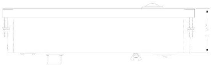
natural_image
Technical line drawing of a rectangular structure with supports and a curved top (no text or symbols)| ZONE | ISS | DESCRIPTION | DATE | APPR'D |
| REVISIONS | ||||
| PROPRIETARY NOTICE - THIS DOCUMENT CONTAINS INFORMATION WHICH IS SOUL PRODUIT OF KONGSBERG SMRAD MESOLECH LTD. AND IS RECEIVED IN CONFIDENCE IN CONTEIN IS MAY NOT BE DISCUCED OR REPRODUCED IN ANY WAY WITHOUT WRITTEN CONSENT OF KONGSBERG SMRAD MESOLECH LTD. | APPROVALS | DATE | Kongsberg Simrad Mesolech Ltd. | ||
| DRAWN | ACS | 20018 | |||
| CHECKED ENGR. | |||||
| ISSUED | |||||
| NEXT ASSEY | MODEL | OUTLINE & INSTALLATION DRAWING - SLGS USER INTERFACE HMS | |||
| CONFIDENTAL DO NOT COPY | SIZE: MSCW NO B 10965 | TYPE: MD | DWG NO. 901-60101001 | ||
| ROAD NAME: | WD.NO. | SHEET 1 OF 1 | |||


NOTES:
1. CHASSIS WIRING DWG 901-60121003
2. SECURE UNSECURED FASTENERS WITH LOCUTIVE 242 DE EQUIVALENT
3. DIMENSIONS IN INCHES
| ZONE | ISS | DESCRIPTION | DATE | APPR'D |
| PROPERTEAL NOTICE - THIS DOCUMENT CONTAINS INFORMATION WHICH IS SOLE PROPERTY OF KONGSBER SHIP-ID MESOTECH LTD. AND IS RECEIVED IN CONFIDENCE. IT'S CONTENTS MAY NOT BE DISCLOSED TO REPRODUCED IN 2417. VERY WITHOUT WRITTEN CONSENT OF KONGSBER SHIP-ID MESOTECH LTD. | APPROALS | DATE | Kongsberg Simrad Mesotech Ltd. | |||
| DRAWN | 4CS | 030100 | ||||
| CHECKED | ASSEMBLY DRAWING - SL30 USER INTERFACE BOX | |||||
| EXP | ||||||
| ISSUED | ||||||
| HEAT ASSY | MODEL | SEE | HIGH NO | TYPE | DWG NO | |
| B | IC965 | HD | 901-60121000 | |||
| CONFIDENTIAL DO NOT COPY | ||||||
| ←→→ | + | SCALE 1/2 | R.O. NO | SHEET 1 OF 1 | ||

NOTES:
DIMENSIONS: INCHES ± 1/2"
| ZONE | ISS | DESCRIPTION | DATE | APPR'D |
| PROPERTI-LET NOTICE - THIS DOCUMENT CONTAINS INFORMATION WHICH IS SOLE PROPERTY OF KONGSBER SHIP-ID HESOTECH LTD. AND IS RECEIVED IN CONFERENCE. IT'S CONTENTS MAY NOT HIT DESCLOSED FOR REPRODUCED BY 101 TAY WITHOUT WRITTEN CONSENT OF KONGSBER SHIP-ID HESOTECH LTD. | APPROVALS | DATE | Kongsberg Simrad Mesotech Ltd. WIFING DRAWING - SL30 USER INTERFACE BOX | ||||
| DRAWN | 4CS | 09/01/06 | |||||
| CHECKED | |||||||
| EXP | |||||||
| ISSUED | |||||||
| HEAT ASSY | MODEL | SEE | HIGH NO | TYPE | DWG NO | 901-60121003 | |
| CONFIDENTIAL DO NOT COPY | B | 1C965 | HD | NO | 1.0 | ||
| ←→ + | SCALE INT'D 100 HD | SHEET 1 OF 1 | |||||


NOTES:
1. CHASSIS WIRING DWG 901-60131003
2. SECURE UNSECURED FASTENERS WITH LOCUTIE 242 OR EQUIVALENT
3. DIMENSIONS IN INCHES
| ZONE | ISS | DESCRIPTION | DATE | APPR'D |
| PROPERTEAL NOTICE - THIS DOCUMENT CONTAINS INFORMATION WHICH IS SOLE PROPERTY OF KONGSBER SHIP-ID MESOTECH LTD. AND IS RECEIVED IN CONFIDENCE. ITS CONTENTS MAY NOT BE DISCLOSED TO PEPPRODUCED IN 241. NOV WITHOUT WRITTEN CONSENT OF KONGSBER SHIP-ID MESOTECH LTD. | APPROALS | DATE | Kongsberg Simrad Mesotech Ltd. | |||
| DESCRIPTION | APR1129 | |||||
| CHECKED | ASSEMBLY DRAWING - SL30 POWER/TELEHETRY BOX | |||||
| EXP | ||||||
| ISSUED | ||||||
| HEAT ASSY | MODEL | SEE | HIGH NO | TYPE | DWG NO | |
| B | 1C965 | HD | 901-60131000 | |||
| CONFIDENTIAL DO NOT COPY | ||||||
| ←→→ + | SCALE 1/2 | R.O. NO | SHEET 1 OF 1 | |||

| PROPERTI-FL NOTICE - THIS DOCUMENT CONTAINS INFORMATION WHICH IS SOLE PROPERTY OF LONGSBERG SIMRAD HESOTECH LTD. AND IS RECEIVED IN CONFIDENCE. ITS CONTENTS MAY NOT BE DISCLOSED OR REPRODUCED IN ANY WHAT WITHOUT WRITTEN COSENT OF LONGSBERG SIMRAD HESOTECH LTD. | APPROV-ALS | DATE | Kongsberg Simrad Mesotech Ltd. | ||||||||
| DF-VAN 4CS | 021204 | ||||||||||
| CHECKED | VIRING INSTALLATION DRAWING - SL30 POWER/TELENETRY BOX | ||||||||||
| DISP | |||||||||||
| ISSUED | |||||||||||
| HELT 455Y | MODEL | SEE | INSON NO | TYPE | DWG NO | 901-60131002 | |||||
| CONFIDENTIAL DO NOT COPY | B | JC965 | HD | HD | 901-60131002 | ISS 1.0 | |||||
| PEVISIONS | +----+ | + | SCALE: 3/4 | R.O. HD | SHEET 1 OF 3 | ||||||
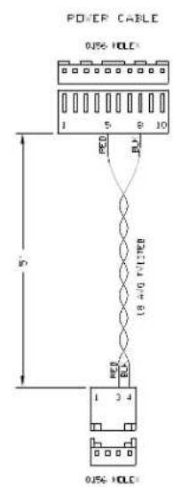
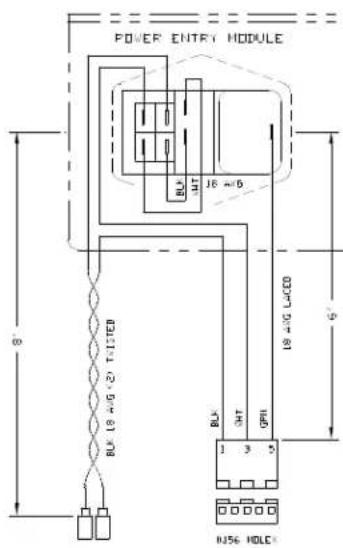
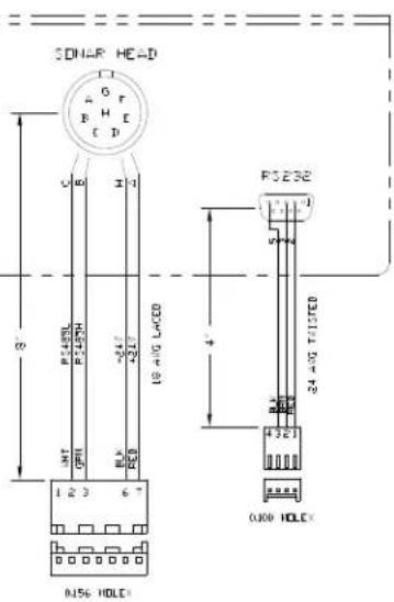
NOTES: DIMENSIONS: INCHES ± 1/2"
| ZONE | ISS | DESCRIPTION | DATE | APPR'D |
| PEVISIONS | ||||
| PROPERTEAL NOTICE - THIS DOCUMENT CONTAINS INFORMATION WHICH IS SOLE PROPERTY OF KONGSBER SHIP-2D HESOTECH LTD. AND IS RECEIVED IN CONFIDENCE. IT'S CONTENTS MAY NOT BE DISCLOSED TO REPEPRODUCED BY 101 I/II WITHOUT WRITTEN CONSENT OF KONGSBER SHIP-2D HESOTECH LTD. | APPROALS | DATE | Kongsberg Simrad Mesotech Ltd. WIFING DRAWING - SL30 POWER/TELEHETRY BOX | ||||
| DRAWN | 4CS | 081206 | |||||
| CHECKED | |||||||
| DISP | |||||||
| ISSUED | |||||||
| HEAT ASSY | MODEL | SEE HIGH NO TYPE DNG NO B IC965 HD HD 901-60131003 KS SCALE INT#2 #O NO SHEET J OF J | |||||
| CONFIDENTIAL DO NOT COPY | |||||||
| +---+ | |||||||
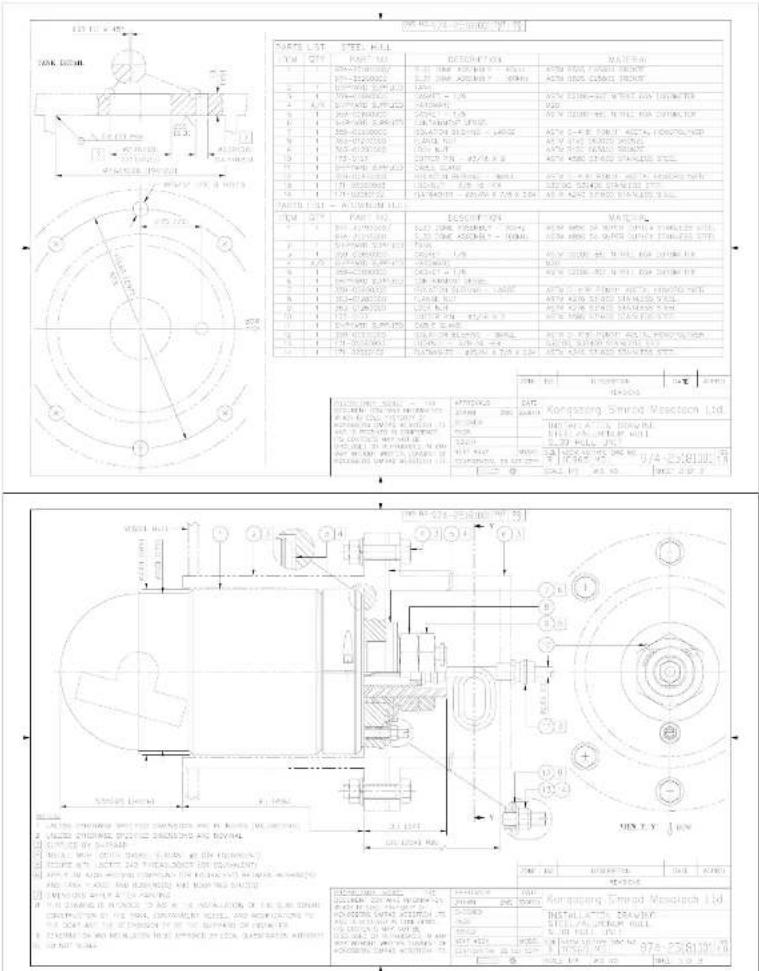
| DATE | LOT | SHEET | HILL |
| 1 YR | 20" | PART NO. | DESCRIPTION |
| 1 | 3" | BALANCE SHEET | |
| 1Y-12-20025 | BALANCE SHEET | BALANCE SHEET | |
| 1Y-12-20025 | BALANCE SHEET | BALANCE SHEET | |
| 2 | 1 | BALANCE SHEET | BALANCE SHEET |
| 3 | 1 | BALANCE SHEET | BALANCE SHEET |
| 4 | A/1 | BALANCE SHEET | BALANCE SHEET |
| 5 | 1 | BALANCE SHEET | BALANCE SHEET |
| 6 | 1 | BALANCE SHEET | BALANCE SHEET |
| 7 | 1 | BALANCE SHEET | BALANCE SHEET |
| 8 | 1 | BALANCE SHEET | BALANCE SHEET |
| 9 | 1 | BALANCE SHEET | BALANCE SHEET |
| 10 | 1 | BALANCE SHEET | BALANCE SHEET |
| 11 | 1 | BALANCE SHEET | BALANCE SHEET |
| 12 | 1 | BALANCE SHEET | BALANCE SHEET |
| 13 | 1 | BALANCE SHEET | BALANCE SHEET |
| 14 | 1 | BALANCE SHEET | BALANCE SHEET |
| 15 | 1 | BALANCE SHEET | BALANCE SHEET |
| 16 | 1 | BALANCE SHEET | BALANCE SHEET |
| 17 | 1 | BALANCE SHEET | BALANCE SHEET |
| 18 | 1 | BALANCE SHEET | BALANCE SHEET |
| 19 | 1 | BALANCE SHEET | BALANCE SHEET |
| 20 | 1 | BALANCE SHEET | BALANCE SHEET |
| 21 | 1 | BALANCE SHEET | BALANCE SHEET |
| 22 | 1 | BALANCE SHEET | BALANCE SHEET |
| 23 | 1 | BALANCE SHEET | BALANCE SHEET |
| 24 | 1 | BALANCE SHEET | BALANCE SHEET |
| 25 | 1 | BALANCE SHEET | BALANCE SHEET |
| 26 | 1 | BALANCE SHEET | BALANCE SHEET |
| 27 | 1 | BALANCE SHEET | BALANCE SHEET |
| 28 | 1 | BALANCE SHEET | BALANCE SHEET |
| 29 | 1 | BALANCE SHEET | BALANCE SHEET |
| 30 | 1 | BALANCE SHEET | BALANCE SHEET |
| 31 | 1 | BALANCE SHEET | BALANCE SHEET |
| 32 | 1 | BALANCE SHEET | BALANCE SHEET |
| 33 | 1 | BALANCE SHEET | BALANCE SHEET |
| 34 | 1 | BALANCE SHEET | BALANCE SHEET |
| 35 | 1 | BALANCE SHEET | BALANCE SHEET |
| SALADAS, SANTIL, T. THE CERAMIN, CHERA, W. MICHIGAN, N. KONCHINI, KONCHINI, P. KONCHINI, KONCHINI, W. MICHIGAN, T. THE KONCHINI, KONCHINI, P. KONCHINI, KONCHINI, W. MICHIGAN, T. THE KONCHINI, KONCHINI, P. KONCHINI, KONCHINI, W. MICHIGAN, T. THE KONCHINI, KONCHINI, P. KONCHINI, KONCHINI, W. MICHIGAN, T. THE MUSHI, MUSHI, P. KONCHINI, KONCHINI, W. MICHIGAN, T. THE MUSHI, MUSHI, P. KONCHINI, KONCHINI, W. MICHIGAN, T. THE MUSHI, MUSHI, P. KONCHINI, KONCHINI, W. MICHIGAN, T. THE MUSHI, MUSHI, P. KONCHINO, MUSHI, W. MICHIGAN, T. THE MUSHI, MUSHI, P. KONCHINO, MUSHI, W. MICHIGAN, T. THE MUSHI, MUSHI, P. KONCHINO, MUSHI, W. MICHIGAN, T. THE MUSHI, MUSHI, P. KONCHINO, MUSHI, W. MICHIGAN, T. T. T. T. T. T. T. T. T. T. T. T. T. T. T. T. T. T. T. T. T. T. T. T. T. T. T. T. T. T. T. T. T. T. T. T. T. T. T. T. T. T. T. T. T. T. T. T. T. T. T T. T. T. T. T. T. T. T. T. T. T. T. T. T. T. T. T. T. T. T. T. T. T. T. T. T. T. T. T. T. T. T. T. T. T. T. T. T. T. T. T. T. T. T. T. T. T. T. T. T. |

| ITEM | QTY | PART NO. | DETAIL NAME | MATERIAL |
| 1 | 1 | ATM-2013000/ATM-2020000 | LTR-THE MOUNTING (LTR) | ATM BHA TANGU DHUCT |
| LTR-2013000 | LTR-2013000 ASSEMBLY (SMB) | ACN 2020 GANUL DHUCT | ||
| 2 | 1 | SPRING RED CAPS | CAPS | |
| 3 | 1 | TMT-CAPS | CAPS - LTR | AVY 2020-HOT WITH ACHI THOMETER |
| 4 | A | SPRING RED CAPS | CAPS - LTR | AVY 2020-HOT WITH ACHI THOMETER |
| 5 | 1 | SPRING RED CAPS | CAPS - LTR | AVY 2020-HOT WITH ACHI THOMETER |
| 6 | 1 | SPRING RED CAPS | CAPS - LTR | AVY 2020-HOT WITH ACHI THOMETER |
| 7 | 1 | SPRING RED CAPS | CAPS - LTR | AVY 2020-HOT WITH ACHI THOMETER |
| 8 | 1 | ALABY-2020000 | ALABY-2020 | AVY 2020 HANANA DHUCT |
| 9 | 1 | NAS-2020000 | NAS-LTR | AVY 2020 HANANA DHUCT |
| 10 | 1 | SPRING RED CAPS | SPRING RED - ALABY-2020 | AVY 2020 HANANA DHUCT |
| 11 | 1 | SPRING RED CAPS | SPRING RED | AVY 2020 HANANA DHUCT |
| 12 | 1 | SPRING RED CAPS | SPRING RED | AVY 2020 HANANA DHUCT |
| 13 | 1 | SPRING RED CAPS | SPRING RED | AVY 2020 HANANA DHUCT |
| 14 | 1 | SPRING RED CAPS | SPRING RED | AVY 2020 HANANA DHUCT |
| UNLESS OTHERWISE SPECIFIEDDIRECTIONS ARE IN HICHSTOLEP-AHES ARE:DECIMALS (PROCTIONS) UNHILES.XX ±0.006 ±1/32 ±30XXX±0.003 | APPROVALS | DATE | Kongsberg OtherWIDE Mesotech Ltd. | |||||
| DPAM | 4CS | 081211 | ||||||
| CHECKED | ASSEMBLY DRAWING -SL30 TRANSCEIVER BOX | |||||||
| DISP | ||||||||
| ISSUED | ||||||||
| HEET ASSY | MODEL | SIZEE | HSCH NOIC965 | TYPEHD | DWG NO974-35051000 | |||
| CONFIDENTIAL DO NOT COPY | ||||||||
| DO NOT SCALE DRAWING | ←→→ | + | SCALE 1/2 | R.O. NO. | SHEET 1 OF 1 | |||
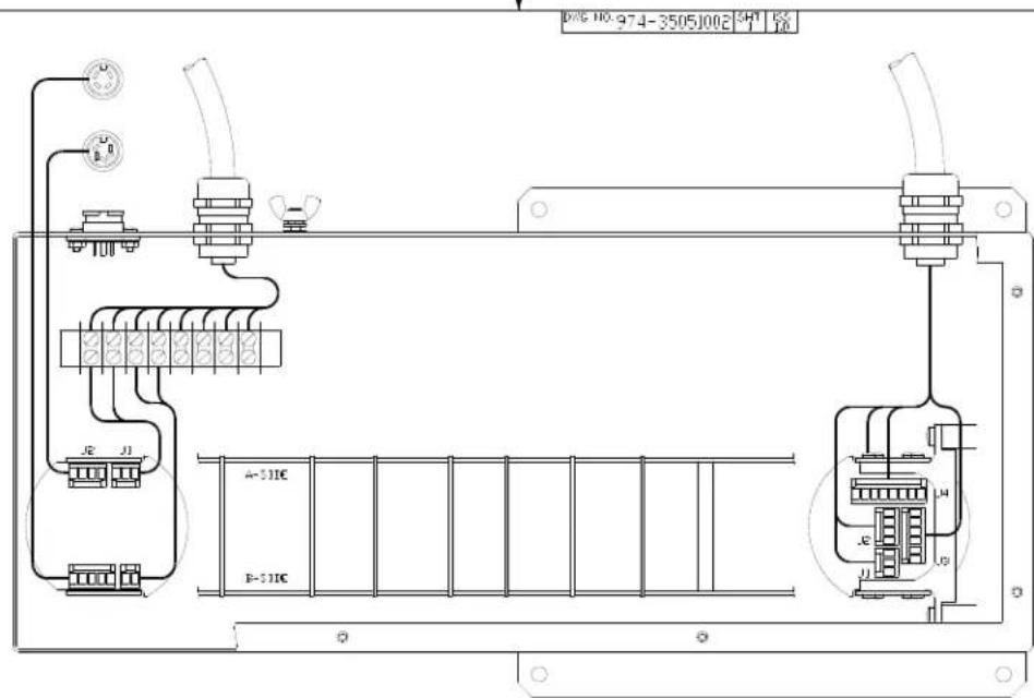
| ZONE | ISS | DESCRIPTION | DATE | APP'D |
| PEVISIONS | ||||
| PROPRIET-FL NOTICE - THIS DOCUMENT CONTAINS INFORMATION (IIHCH IS SOLE PROPERTY OF LONGSBERG SHIP-2 HESOTECH LTD. AND IS RECEIVED IN CONFIDENCE, ITS CONTENTS MAY NOT BE CLOSED OF REPRODUCED IN ANY (II) WITHOUT WRITTEN CONSENT OF LONGSBERG SHIP-2 HESOTECH LTD. | APPROALS | DATE | Kongsberg Simrad Mesotech Ltd. VIRING INSTALLATION DRAWING - SL30 TRANSCIEVER BOX | ||
| DRAWN | 4CS | 081282 | |||
| CHECKED | |||||
| EXP | |||||
| ISSUED | |||||
| HEAT ASSY | MODEL | SEE | HICH NO | TYPE | |
| B | IC965 | HD | |||
| CONFIDENTIAL DO NOT COPY | 974-35051002 | ||||
| ←→ + | SHEET 1 OF 1 | ||||

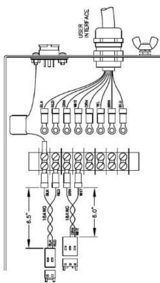
DWG NO.974-35051003 SHT ISS 1.1

- SL 30/35 HULL SONAR OPERATORS MANUAL
- Kongsberg Simrad Mesotech Ltd Products Warranty Policy
- Underwater Equipment:
- Warranty on Parts or Equipment Replacement:
- Consumable Materials:
- Warranty Service:
- DISCLAIMER
- LIST OF CONTENTS
- MODIFICATION RECORD
- PART 1
- Equipment Configuration
- Important notice:
- System Diagram
- Display
- Processor Unit
- Control Panel and Interface Unit
- Sonar Room Unit
- WARNING!!
- SL 30/35 TECHNICAL SPECIFICATIONS
- - Processing Unit
- - Data Input/output
- - Range
- - Tilt
- - Stabilization
- - Operating Panel
- Hull Unit
- - Transceiver Unit
- - Sonar Dome Unit
- - Options:
- PART 2
- SYSTEM DESCRIPTION
- SYSTEM DESCRIPTION ......2.3
- SYSTEM DESCRIPTION
- INTRODUCTION
- Basic Principles
- Determining Target Position
- Forming an Image
- Wheelhouse Units Description
- Display Monitor
- Processor Unit
- Control Panel
- Interface Unit
- Interconnect Cables
- Sonar Room Units Description
- Transceiver Unit
- Lower and Raise Unit
- Hull Sonar Dome Unit
- Tank Flange Assembly
- Interconnect Cables
- Options
- Motion Sensor
- Audio Warning Speaker
- Remarks
- Warning
- Copyright
- PART 3
- SL 30/35 CONTROL PANEL
- SL 30/35 CONTROL PANEL OPERATION....3.3
- SL 30/35 CONTROL PANEL OPERATION
- INTRODUCTION
- CONTROL PANEL
- MAIN POWER SWITCH
- Power ON/OFF Buttons
- Sonar Dome Transducer Buttons
- Sonar Settings Button
- Roller Ball and Mouse Buttons
- Sonar Selection Buttons
- Range Buttons
- Gain Buttons
- Scan Buttons
- Tilt Buttons
- Sector Control Buttons
- Move Sector Left Button
- Move Sector Right Button
- Narrow Sector Button
- Widen Sector Button
- Sector Aiming Mode Buttons
- Utilities Buttons
- Off Center Button
- Zoom Button
- Stabilize Button
- Speaker Button
- Target Track and Lock Buttons
- Auto and Manual Search Buttons
- Symbol Buttons
- Latitude / Longitude Button
- Event Mark Button
- Cursor Buttons
- User Buttons
- Display Mode Buttons
- Horizontal Display Mode Button
- Bow Up Display Mode Button
- Vertical Fan Mode Button
- Sounder Mode Button
- Horizontal Mode with History Mode button
- Horizontal Mode with Real Time Vertical Strata Mode Button
- RX and TX Indicator LED
- Alarm Indicator LED
- Keyboard (KBD) External Plug-in
- Panel Light Dimmer Sensor
- Menu Description
- PART 4
- MENU AND SOFTWARE DESCRIPTION
- MENU AND SOFTWARE DESCRIPTION....4.5
- MENU AND SOFTWARE DESCRIPTION
- INTRODUCTIONS
- ASSUMPTIONS
- SCOPE OF THIS MANUAL
- SOFTWARE INSTALLATION
- HARDWARE SECURITY KEY
- Important Note
- MAIN CONTROL PANEL
- THE TOOLBARS
- SONAR TOOLBAR
- 974-25007001/2.0 SL 30/35 Hull Sonar Operators Manual Page 4.10 Menu and Software Description
- MARKER TOOLBAR
- THE STATUS BAR
- REFERENCE CURSORS
- KEY SETTINGS PANEL
- HOW TO CONNECT AND SETUP A HEAD (FIRST TIME OPERATION)
- HOW TO USE THE SONAR (SOME RULES OF THUMB)
- HOW TO RESET TO THE FACTORY DEFAULT SETTINGS
- To reset all sonar settings to their factory default values:
- HOW TO USE THE BASIC SONAR CONTROLS
- To use the basic sonar controls:
- HOW TO SELECT UNITS OF MEASURE (FEET, YARDS, METERS)
- To select the units of measure for the sonar:
- HOW TO SET OR ESTIMATE THE VELOCITY OF SOUND
- HOW TO INTERPRET THE SONAR IMAGE
- The Color Palette
- Bright Spots
- Dark Spots
- Shadows
- Noise and Interference
- Masking Effects
- Range Scale and Target Size
- Mirroring Effects
- HOW TO GET THE HIGHEST RESOLUTION IMAGE
- To get the highest possible image quality:
- HOW TO GET THE FASTEST UPDATE RATE
- To get the fastest update rate on a particular area:
- HOW TO USE THE MULTIPLE USER FEATURE
- To create a new user name and configuration:
- To select a different user configuration:
- HOW TO RECORD AND PLAYBACK SONAR DATA
- To record sonar data:
- To playback sonar data:
- HOW TO CUSTOMIZE THE HEAD SETTINGS DISPLAY
- HOW TO CREATE A CUSTOM GAUGE WINDOW
- HOW TO SHOW A CLOSED OR HIDDEN GAUGE WINDOW
- ABOUT NETWORKING
- STAND ALONE MODE
- Server Mode
- Passive Client Mode
- Active Client Mode
- HOW TO SETUP A NETWORK CONNECTION (WINDOWS NT/2000)
- Important Note:
- To setup a network connection:
- HOW TO SETUP THIS SONAR AS THE SERVER
- To setup this sonar as the server:
- HOW TO SETUP THIS SONAR AS A PASSIVE CLIENT
- To setup this sonar as a passive client:
- HOW TO SETUP THIS SONAR AS THE ACTIVE CLIENT
- To setup this sonar as the active client:
- If the sonar is currently configured as a server:
- HOW TO EXPORT DATA TO A FILE
- To export data to a file:
- HOW TO EXPORT DATA TO A SERIAL PORT
- To export data to a serial port:
- HOW TO SETUP FOR AND DISPLAY GPS DATA
- To setup the system to accept position data from a GPS receiver:
- To setup the system to display position data from a GPS receiver:
- HOW TO SETUP FOR AND DISPLAY COMPASS DATA
- To setup the system to accept heading data from a compass:
- HOW TO SETUP FOR AND DISPLAY OTHER NMEA DATA
- To setup the system to accept data from an NMEA device:
- To setup the system to display data from an NMEA device:
- HOW TO SETUP USER DEFINED SENSORS
- To setup the system to display data from a user defined sensor:
- THE FILE MENU
- THE VIEW MENU
- CONTROL PANEL MENU
- DISPLAY MENU
- MESSAGE LOG MENU
- USERS MENU
- THE OPERATIONS MENU
- PLAYBACK DATA MENU
- THE TARGETS MENU
- NETWORK MENU
- THE WINDOW MENU
- THE HELP MENU
- POPUP MENUS
- HEAD SETTINGS GAUGE WINDOW
- ABOUT DIALOG BOX
- ADD USERS AND GROUPS (WINDOWS NT/2000 OR XP)
- CLIENT LIST DIALOG BOX
- DISPLAY SETTINGS DIALOG BOX
- Display Settings: Colors
- Palette Styles
- Primary Overlay Colors buttons.
- The Palette Threshold
- Display Settings: Controls
- Sector View
- Display Gain
- Rx Gain Type
- Scan marker
- Grid control
- Timer
- Scroll Speed
- Distributed COM Configuration Properties Applications
- Distributed COM Configuration Properties Default Properties
- Export Data File Selection Dialog Box
- Export Dialog Box
- Export: Export Selection
- Automatic File
- Export: Ports Configuration
- Head Settings Dialog Box
- Head Settings: Scan
- Horizontal/Vert Fan
- Horiz with History
- Head Settings: Transmit
- Head Settings: Info
- Machine Name Dialog Box
- Parameters Dialog Box
- Parameters: Magnetic Variation
- Parameters: Sound Velocity
- Parameters: Units of Measure
- SL35 Properties Location (Windows NT/2000)
- SL35 Properties Security (Windows NT/2000)
- Playback Data Dialog Box
- Read Event Log File Dialog Box
- Record Data Dialog Box
- Record Dialog Box
- User Configuration Dialog Box
- File Types Used by the SL35 System
- Factory Reset Settings
- Gauge Windows: Customize
- 4.59.14
- Magnifier
- Window
- Cursors Gauge Window
- Pointer Gauge Window
- Target Position Gauge Window
- Playback Progress Display
- Scope Graph Display
- Security Key Warning
- Sensors Configuration Dialog Box
- Sensors Sensor Selection
- Sensors Ports Configuration
- User Defined Sensors
- Start Character
- Field Delimiter
- Format
- Example
- Sensors Data Display Box
- System Configuration Dialog Box
- System Message Log Dialog Box
- AUDIO SET-UP WINDOW
- POST PROCESSING SET-UP WINDOW
- AUDIO AND POST PROCESSING SET-UP PROCEDURE
- PART 5
- SELECTING SETTINGS
- SELECTING SETTINGS ....5.3
- SELECTING SETTINGS
- OVERVIEW
- DEFINE USER / OPERATION SETTINGS
- User 1 Settings
- User 1, Operation 1 Settings
- Creating Operation 1, 2, 3 and 4 Settings
- DISPLAY MODE
- Horizontal Display Mode with Control Panel
- Horizontal Display Mode without Control Panel
- Bow Up Display Mode
- Vertical Fan Display Mode without Control Panel
- Vertical Fan Display Mode with Control Panel
- Sounder Display Mode without Control Panel
- Horizontal with History Display Mode
- Horizontal with Strata Display Mode
- Horizontal with Strata and Control Panel Display Mode
- NEW DISPLAY MODE
- Dual Sonar Bow-Up and Catch Display Mode
- Dual Sonar Catch Display Mode
- Catch Display Mode
- TILT ANGLE SETTINGS
- Discriminating Fish Echoes
- Tilt Angle and Beam Coverage
- PITCH AND ROLL CALIBRATION
- KEY SETTINGS
- AGC Setting
- RX Gain Response Setting
- RCG Setting
- Pulse Length Setting
- Optimize Resolution
- Maximize Range
- Peak Detection
- PART 6
- INSTALLATION, START-UP
- AND TEST
- INSTALLATION, START-UP AND TEST ......6.3
- INSTALLATION, START-UP AND TEST
- INSTALLATION PROCEDURE
- SURFACE UNIT ELECTRONICS INSTALLATION
- Mounting of Units
- Power Considerations
- Connecting the Display Unit
- Note!
- Connecting the Processor
- Connecting the Operating/Interface unit
- Connecting DGPS
- Network LAN Connection
- SONAR ROOM HULL AND TRANSCEIVER UNIT INSTALLATION
- Sonar Room Mounting Space
- Mounting the Transceiver unit
- Mounting the Lower and Raise Hoist Unit
- Mounting the Motion Sensor
- Mounting the Tank (Trunk) Unit
- ASSEMBLING THE FLANGE, SONAR DOME, SHAFT AND TANK GUIDE
- Required Tools
- Tank Flange and Shaft Prepping
- Assembling the Sonar Dome, Shaft and Tank Guide Assembly
- Sonar Dome, Shaft and Tank Guide Assembly
- Mounting the Flange and Sonar Dome to the Tank (Trunk)
- Mounting the Hoist Unit
- Mounting the Transceiver
- INTERCONNECTION WIRING DIAGRAM
- Motion Sensor Electrical Connection
- SL 30 OR SL 35 SYSTEM START-UP AND TEST
- SL 30/35 Start Up
- Power-Up Configuration
- SL 30 or SL 35 Start up Procedure
- SL 30/35 RUN UP Procedure
- Display Settings
- Control Setting
- Readout Options
- SL 30/35 Settings
- Transmit Setting Page
- TVG Setting Page
- Info Page
- Sensor Page
- User Setting
- Save Additional User Operation or Specific Fishery Setting
- USER 1, 2, 3, 4 SETTINGS
- Note:
- AUDIO AND POST PROCESSING SET-UP
- Post Processing
- Audio Set-up
- PART 7
- TROUBLESHOOTING AND MAINTENANCE
- TROUBLESHOOTING AND MAINTENANCE....7.3
- TROUBLESHOOTING AND MAINTENANCE
- INTRODUCTIONS
- SYSTEM OVERVIEW
- HANDLING & MAINTENANCE
- Wheelhouse Electronics
- Hull Unit
- PREVENTIVE MAINTENANCE
- Lubrication (SL 35 Only)
- Manually Raising Sonar Dome (SL 35 Only)
- Lower and Raise unit (SL 35 Only)
- Tank Flange shaft Bearing, Seals and Sonar Dome (SL 35 Only)
- SL 35 Shaft and SL30/35 Sonar Dome Damage
- Corrosion
- TROUBLESHOOTING
- - Cannot turn the power ON
- - Irregular bottom echo's
- - Weak Echoes
- - Noise on the Screen
- ERROR MESSAGES LOG
- PART 8
- ATTACHMENTS AND DRAWINGS
- ATTACHMENTS AND DRAWINGS.... 8.3
- ATTACHMENTS AND DRAWINGS
- LIST OF ATTACHMENTS
- LIST OF DRAWINGS
- SL 30/35 Hull Sonar Surface Processor Setup Instructions
- SL 30/35 HULL SONAR SURFACE PROCESSOR SETUP INSTRUCTIONS....2
- - Windows XP
- Windows XP Service Pack Installation
- - Windows 2000
- SL 30/35 Hull Sonar Surface Processor Setup Instructions 901-10111802 / Issue 1.4
- Page 4
- SETUP THE BOOT TIME
- SETUP THE REGISTRY FOR AUTOMATIC LOGON
- SL 30/35 Hull Sonar Surface Processor Setup Instructions 901-10111802 / Issue 1.4 Page 5
- INSTALL THE SL 30/35 HULL SONAR SOFTWARE
- SL 30/35 Hull Sonar Surface Processor Setup Instructions 901-10111802 / Issue 1.4 Page 6
- SETUP THE STARTUP FOR AUTOMATIC SL 30/35 EXECUTION
- SETUP THE NETWORKING
- SL 30/35 Hull Sonar Surface Processor Setup Instructions 901-10111802 / Issue 1.4 Page 8
- SL 30/35 Hull Sonar Surface Processor Setup Instructions 901-10111802 / Issue 1.4 Page 9
- SL 30/35 Hull Sonar Surface Processor Setup Instructions 901-10111802 / Issue 1.4 Page 10
- SL 30/35 Hull Sonar Surface Processor Setup Instructions 901-10111802 / Issue 1.4 Page 11
Brand : SIMRAD
Model : SL35
Category : Marine Radar