
SH80 - Marine Radar SIMRAD - Free user manual and instructions
Find the device manual for free SH80 SIMRAD in PDF.


| Type | High frequency fishery sonar (omnidirectional) |
| Standard frequency | 116 kHz |
| Optional frequencies | 110–122 kHz in 1 kHz steps (multiple frequency option) |
| Beam tilt | +10° to -60° (electronic) |
| Stabilization | Electronic pitch and roll compensation up to ±20° |
| Transducer type | Cylindrical, 480 elements |
| Transmitter / Receiver channels | 240 transmitter / 480 receiver |
| Display | High-resolution color LCD |
| Operating system | Microsoft Windows XP (Sonar Processor Unit) |
| Power supply | 115/230 Vac (main units) |
| Hull unit travel | Lowerable 1.0 m below hull; manual emergency crank |
| Display modes | Bow Up, North Up, True Motion, 180°/Audio, 270°/Vertical, Bow Up/Vertical, True Motion/Vertical, Dual 1, Dual 2 |
| Signal processing filters | RCG (Reverberation Controlled Gain), PP Filter, TVG (Time Variable Gain) |
| Peripheral interfaces | Speed log, gyro, GPS, Simrad echo sounders, PI32/PI44 catch monitoring, trawl instrumentation (FS 900, FS 3300, ITI), current meter, radio buoy |
| Data storage | Store/Recall of single images or sequences; user settings |
| Protection | Hoist motor overload protection; emergency hoist/lower via S302 switch |
| Maintenance intervals | Clean dust filters every 3 months; lubricate hull unit every 3 months; clean transducer when docked |
Frequently Asked Questions - SH80 SIMRAD
User questions about SH80 SIMRAD
0 question about this device. Answer the ones you know or ask your own.
Ask a new question about this device
Download the instructions for your Marine Radar in PDF format for free! Find your manual SH80 - SIMRAD and take your electronic device back in hand. On this page are published all the documents necessary for the use of your device. SH80 by SIMRAD.
USER MANUAL SH80 SIMRAD
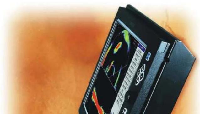
High frequency fishery sonar
natural_image
Close-up of a black electronic device with a display screen showing colorful graphics and buttons, placed on an orange textured surface (no visible text or symbols)850-164385/Rev.C
SH80
Highfrequencyfisherysonar
Operatormanual
About this document
| RevDateWrittenbyCheckedbyApprovedby | ||||
| Rev.C | 11.02.05RBrS∅JOBG | |||
| Updatedforsoftwareversion1.2.X | ||||
© 2005 Simrad AS
ISBN 82-8066-007-0
All rights reserved. No part of this work covered by the copyright hereon may be reproduced or otherwise copied without prior permission from Simrad AS.
The information contained in this document is subject to change without prior notice. Simrad AS shall not be liable for errors contained herein, or for incidental or consequential damages in connection with the furnishing, performance, or use of this document.
Sections
1. System description
ThischapterprovidesabriefintroductiontotheSH80,anddefinesthemain units.Refertopage1.
2. Display modes
Thischapterdefinestheavailableoperationaldisplaymodes.Refertopage 13.
3. Sonar Operating Panel
ThemainfunctionsoftheSH80iscontrolledbyadedicatedkeyboard; the operatingpanel. Thecontrolsandfunctionsofthisunitisdescribed. Refer topage23.
4. Operation
ThischapterprovidesthebasicknowledgeonhowtooperatetheSI180 sonar.Refertopage36.
5. Menu description
OperationoftheSH80sonarisalsomenubased.andthemenuswill automaticallyadjusttoyourcurrentoperationalmodes.Thischapter explainsallthemenus,andreferesdirectlytotherelevantparameters.Refer topage56.
6. Parameters
AlltheoperationalfunctionsoftheSH80sonararecontrolledbythe parametersaccessedfromthemenusystem.Inthischapter.allthe
SYSTEM DESCRIPTION 1......
Introduction 1.
System overview 2.
Main units 2.
Wheelhouse units 2.
Sonar room units 3
System diagram 4
Options 6
General 6
Multiple-frequency 6
Scientific output 6
Functional description 7
Introduction 7
Functional principles 7
Stabilization system 9
Reception 9
Transmission 10
Peripheral equipment 12
DISPLAY MODES 13....
Introduction 13.
Bow Up 14
North Up 15
True Motion 16
Operator manual
Tilt 34.
Various 35.
OPERATION 36....
Introduction 36.
Maintaining the sonar 37
Maintenance procedures 37
Important when docking the vessel 37
Start and stop procedures 38
Start procedure 38
Stop procedure 39
Dry-docking safety measures 40
Menu operation 41
Introduction 41
Screen presentations 42
Menu structure 44
Menu buttons 45
Selecting a new parameter value 46
Stored parameters 48
Visual aids 49
Common information on the display 49
Moving the boundary lines 49
Cosmetics 50
Installation of options 53
Simrad SH80
Pop-up menus 69.
View pop-up 70.
Object pop-up 72.
View menus 74.
GeoView 75.
VerticalView 76.
.CatchView 77
Messages 78
Message categories 78
Warnings 79
Operator alarms 80
System alarms 81
Errors 82
PARAMETERS 83
About parameter dialogues and help 83
Alphabetical list 84
About 85
Beam 86
Bearing (Horizontal) 88
Bearing (Display) 90
Bearing (Vertical) 91
Colour Threshold 92
Colours 93
Operator manual
Message Bar 111....
Mode 112.
Mode Buttons 113.
Movements 114.
Noise Level 115.
Palette 116
Panel Backlight 117
PP Filter 118
Pulse Form 119
Range 121.
Range (Catch View) 122
RCG (Reverberation Controlled Gain) 123
Recall 124
Recall Mode 124.
Ruler 125.
Scale 126
School 127
Scientific Output (Option) 128
Search Sector 129
Search Step 130.
Slant Range/True Range 131
Speed 132
Stabilizer 133
Status 134.
ON-BOARD MAINTENANCE 150....
Introduction 150.
Preventive maintenance schedule 151
Wheelhouse units 152.
Cleaning 152.
Dust filter 152.
Transceiver Unit 154
Dust filter 154.
Replacing fuses 154
Hull unit 156
General 156
Hull unit familiarization 157
Docking the vessel 158
Cleaning the transducer 160
Hoist motor overload protection 161
Emergency hoisting and lowering 162
Lubrication of the Hull Unit 163
SYSTEM DESCRIPTION
Introduction
The Simrad SH80 sonar is an omnidirectional high frequency sonar, designed for all sized fishing vessels, both purse seiners and trawlers. The standard frequency is 116 kHz (multiple frequencies as option), and the beam can be electronically tilted from +10 to -60 degrees.
Great emphasis has been placed on giving the best possible presentations on a high resolution colour display. The processor unit is controlled by Microsoft's Windows XP® operating system, which result in a flexible choice of display modes for a large range of user applications.
The signal processing and beamforming is performed in a fast digital signal processing system using the full dynamic range of the signals. In addition to the traditional single frequency transceiver system, the SH80 sonar contains an advanced frequency modulated filter system (FM).
The cylindrical multi-element transducer allows the omni-directional sonar beam to be tilted electronically down to -60 degrees. This allows you to automatically track schools of fish, and to observe the whole water volume around the vessel. A stabilization system is included for electronic pitch and roll compensation.
System overview
Main units
The Simrad SH80 sonar consists of the following units:
- Wheelhouse units:
- Display monitor
- Sonar Operating Panel
- Sonar Processor Unit
- Sonar Interface Unit
- Sonar room units:
- Transceiver Unit
- Hull Unit
Wheelhouse units
The Display Monitor is a high-resolution colour LCD (Liquid Crystal Display). In addition to the sonar picture, the monitor can also display the user menu for the interactive operation. In order to ease the situation comprehension, certain colours have been chosen to better the distinction between the various elements in the scene.
The Operating Panel contains all necessary control functions
Sonar room units
The Transceiver Unit is located in the sonar room, close to the Hull Unit. One signal cable is used for communication with the Sonar Interface Unit in the wheelhouse. The transceiver performs the signal processing and the digital beamforming of the 240 transmitters and 480 receiver channels, which are located on the eight identical transceiver boards.
The Hull Unit is designed to be lowered 1.0 meters below the ship's hull. The transducer can also be lowered to any selectable middle position. Note that in case of voltage failure, the Hull Unit can be manually raised or lowered by means of a hand crank.
The cylindrical 480-elements transducer allows the sonar beam to give full 360 degrees coverage of the water volume down to -60 degrees.
The sensor for the electronic stabilization of the sonar beams is housed in the Motor Control Unit, which is mounted on the Hull Unit.
Warning: If the transducer hits larger objects or bottom, the transducershaft maybe bent, or in worst case it can be broken off. A brokentransduce shaft will cause water leakage in the top of the shaft. Top prevent larger leakages in such a case, donot_ raisethetransducershaft to the upper position. Top prevent serious damagesitis
System diagram
A simplified SH80 system diagram is shown.
(A)=Colourdisplay
(B)=OperatingPanel
(C)=SonarProcessorUnit
(D)=SonarInterfaceUnit
(E)=Multipleinterfacelinstoperipheralequipment
(F)=TransceiverUnit
(G)=HullUnit
(1)=Wheelhouse
(2)=Sonarroom
System description

flowchart
graph TD
    A["Device A"] -->|115/230 Vac| B["Monitor"]
    B -->|115/230 Vac| C["Device B"]
    C -->|115/230 Vac| D["Device D"]
    D -->|115/230 Vac| E["Device E"]
    E -->|115/230 Vac| F["Device F"]
    F -->|115/230 Vac| G["Device G"]
    style A fill:#f9f,stroke:#333
    style B fill:#ccf,stroke:#333
    style C fill:#cfc,stroke:#333
    style D fill:#fcc,stroke:#333
    style E fill:#cff,stroke:#333
    style F fill:#ffc,stroke:#333
    style G fill:#fcc,stroke:#333
Options
General
The standard SH80 sonar is a single 116 kHz version with beam stabilization.
The beam stabilization was an optional function until 1 January 2003. After that date, the function was included with the standard sonar delivery.
The options described below are pre-programmed into the standard software version, and a code word is required to make the actual option available. Simrad offers a 1 month free test period for certain options. Note that the Scientific Output function is not available for such a test period.
For a permanent installation of a chosen option, a new code word will be released from Simrad when the option is ordered.
Multiple-frequency
In addition to the standard 116 kHz frequency, a multiple frequency option is available. In this multiple frequency version you can select between 13 frequencies from 110 to 122 kHz in 1 kHz steps.
Scientific output
The Scientific Output is designed for research purposes. When
System description
Functional description
Introduction
The basic principles of the SH80 sonar are unique because of the 240 transmitter and 480 receiver channels with their transducer elements spread around on the cylindrical transducer array.
The transmission, reception and data processing are under computer control, and the powerful capabilities of the sonar are the results of sophisticated digital signal processing software and state of the art hardware.
Functional principles
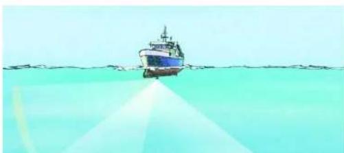
When the Omni beam is tilted, the total beam picture can be compared with folding an umbrella, which means that all beams in 360 degrees around the vessel have the same tilt angle.
Omnibeam principle

natural_image
Illustration of a boat on water with a conical structure in the foreground (no text or symbols)Simrad SH80
60degrees vertical slice

natural_image
Illustration of a boat navigating over water with a curved trajectory, no text or symbols presentOmni/Vertical combination
natural_image
Illustration of a boat on water with a light beam extending from it, no text or symbols presentSystem description
Stabilization system
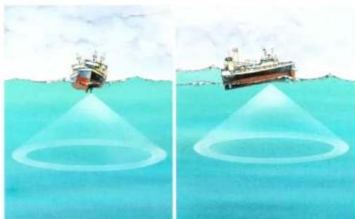
When the beam stabilizer is activated, both horizontal and vertical beams will be stabilized electronically for roll and pitch movements up to ±20 degrees. The beam direction will then change continuously according to the vessel's movements, and secure an optimal contact with the targets even in rough seas.
Stabilization system
natural_image
Two diagrams showing a ship approaching a circular target on the water surface, with no text or symbols present.Reception
A great effort has been made to reduce unwanted noise to get a clean and stable echo presentation. To achieve this goal the sonar receiver has the following filtering possibilities:
However, the sound absorption in salt water increases with the frequency, thus giving the lower frequencies along detection range.
RCG(ReverberationControlledGain)
TheRCGfiltersensesthenoiselevel(reverberation,propeller noise,etc.),andadjuststhegainindividuallyforeachofthe64 receiverbeamsinordertocliminatenoisconthedisplay.The strengthofthefiltercanbeselectedinthemenu.With maximumstrenghtisselected,theRCGwilleffectivelyreduce thebottominshallowwater,whilevariationsonthebottomwill bedisplayed.
Notethatscatteredfishcanbeperceivedasreverberation. The RCGfiltermustthereforebeusedwithcareifscatteredschools aretobedetected.
PPFilter
TheSH80sonarisequippedwithaping-to-pingfiltertogivea cleanandsteadypresentationbyreducingtheinterference and noise. Thisfiltercomparestheechoesfromaselectedamountof transmissions(pings), andanechohastobepresentinthe selectedamountofpingsinordertobepresentonthedisplay.
Notethatinroughseas, whenthebeameasilycanmissthe targetinseveralpings, thePPfiltermustbeusedwithcare.
TVG(TimeVariableGain)
Systemdescription
When the stabilisationsystemisactive, the tilt angle for each beam will automatically be corrected relative to the vessel's pitch and roll movements.
Relatedtopics
→ Frequencyoptions,page6
Peripheral equipment
The SH80 sonar requires connection to a speed log and a course gyro. An inaccurate log or gyro input will cause inaccurate indication of the vessel and target movements.
In addition to log and gyro, the following peripheral equipment can be connected to the sonar.
- A (D)GPS may be connected to the SH80 sonar to establish the vessels position and provide cursor and marker latitude and longitude.
- Simrad echo sounders (EQ, ES and EK Series) provides a bottom plot on the catch data page.
- Simrad PI32 and PI44 Catch Monitoring systems provide the net depth in digits and bars on the catch data presentation.
• Simrad trawl instrumentation; FS 900, FS 3300 or ITI
- FS 900 and FS 3300: The trawl will be displayed in correct depth.
- ITI: The trawl will be displayed in correct size, depth, distance and bearing.
- A Current meter system will indicate the current speed and direction for up to three different depths in the sonar picture.
- A radio buoy system (GPS type) will provide the geographical position of the buoy(s) in the sonar picture.
For connection of any of this peripheral equipment, contact your local dealer.
DISPLAY MODES
Introduction
This chapter describes the SH80 display modes. The various modes represent the graphical presentation of sonar data. Several display modes are available to present the best possible presentations as well as flexible choices for a large range of user applications.
Topics
→ BowUp,page14
→ NorthUp,page15
→ TrueMotion,page16
→ 180 °/Audio,page17
→ 270 °/Vertical,page18
→ BowUp/Vertical,page19
→ TrueMotion/Vertical,page20
→ Dual1,page21
→ Dual2,page22
Display mode selection is made on the second menu button in the main menu. The four first display modes shown can also easily be selected with the four Mode buttons on the Sonar Operating Panel.
Bow Up
When Bow Up mode is selected, the vessel symbol is stationary on the screen with the bow pointing upwards. The echo presentation covers 360 degrees around the vessel, and all echoes are updated for every ping. The distance from the vessel symbol to the outer echo ring is equal to the selected range.

radar
| Angle | Value | |-------|-------| | 0° | 13.056 | | 45° | 13.056 | | 90° | 13.056 | | 135° | 13.056 | | 180° | 13.056 | | 225° | 13.056 | | 270° | 13.056 | | 315° | 13.056 | | 360° | 13.056 | | 405° | 13.056 | | 450° | 13.056 | | 505° | 13.056 | | 550° | 13.056 | | 605° | 13.056 | | 650° | 13.056 | | 705° | 13.056 | | 750° | 13.056 | | 805° | 13.056 | | 850° | 13.056 | | 905° | 13.056 | | 950° | 13.056 | | +∞ | 13.056 |Display modes
North Up
When the North Up mode is selected, true north is always up on the screen. The vessel symbol is stationary with the bow pointing in the vessle's course direction. The movement of the echoes across the screen are controlled by a combination of the vessel's course and speed and the target's own movements.

radar
| Angle | Value | |-------|-------| | 0° | 68° | | 45° | 0.000 | | 91° | 0.000 | | 135° | 0.000 | | 180° | 0.000 | | 225° | 0.000 | | 270° | 0.000 | | 315° | 0.000 | | 360° | 0.000 | | 405° | 0.000 | | 450° | 0.000 | | 505° | 0.000 | | 550° | 0.000 | | 605° | 0.000 | | 650° | 0.000 | | 705° | 0.000 | | 750° | 0.000 | | 805° | 0.000 | | 850° | 0.000 | | 915° | 911.45 |True Motion
When the True Motion mode is selected, the picture is locked to a geographical position, where the vessel moves around the screen according to its present course and speed. All echoes are always presented in their correct position relative to the vessel, and their movements on the screen will be a true representation of the movements of the targets through the water.

Display modes
180°/Audio
When the 180°/Audio mode is selected, the upper half of the screen shows a 180 degrees bow-up presentation, while the lower part is used for a recording of the audio channel.

The audio channel is shown with a continuous white line in the
270°/ Vertical
The 270°/Vertical mode is specially designed for purse seining. The vertical half slice is displayed in the lower left corner for normal setting with the net on the starboard side. If the net is set on the port side, the 60 degrees vertical slice will be displayed in the lower right hand corner.

radar
| Angle | Value | |-------|-------| | 0° | 0 | | 360° | 0 | | 645° | 0 | | 930° | 0 | | 1275° | 0 | | 1690° | 0 | | 1984° | 0 |Display modes
Bow Up / Vertical
When the Bow Up / Vertical mode is selected, the picture is divided into three sections; where the left side is a bow-up presentation similar to the bow-up presentation previously described.

radar
| Angle (°) | Radius (m) | | --------- | ---------- | | 0 | 853 | | 360 | 853 | | 640 | 853 | | 920 | 853 | | 1200 | 853 | | 1500 | 853 | | 1800 | 853 | | 2100 | 853 | | 2400 | 853 | | 2700 | 853 | | 3000 | 853 | | 3300 | 853 | | 3600 | 853 | | 3900 | 853 | | 4200 | 853 | | 4500 | 853 | | 4800 | 853 | | 5100 | 853 | | 5400 | 853 | | 5700 | 853 | | 6000 | 853 | | 6300 | 853 | | 6600 | 853 | | 6900 | 853 | | 7200 | 853 | | 7500 | 853 | | 7800 | 853 | | 8100 | 853 | | 8400 | 853 | | 8700 | 853 | | 9000 | 853 | | 9300 | 853 | | 9600 | 853 | | 9900 | 853 | | +1250 | 853 | | +1650 | 853 | | +2150 | 853 | | +2650 | 853 | | +3150 | 853 | | +3650 | 853 | | +4150 | 853 | | +4650 | 853 | | +5150 | 853 | | +5650 | 853 | | +6150 | 853 | | +6650 | 853 | | +7150 | 853 | | +7650 | 853 | | +8150 | 853 | | +8650 | 853 | | +9150 | 853 | | +9650 | 853 | | +11250 | 853 | | +11750 | 853 | | +12250 | 853 | | +12750 | 853 | | +13250 | 853 | | +13750 | 853 | | +14250 | 853 | | +14750 | 853 | | +15250 | 853 | | +15750 | 853 | | +16250 | 853 | | +16750 | 853 | | +17250 | 853 | | +17750 | 853 | | +18250 | 853 | | +18750 | 853 | | +19250 | 853 | | +19750 | 853 | | +20250 | 853 | | +24250 | 853 | | +24750 | 853 | | +27250 | 853 | | +27750 | 853 | | +29250 | 853 | | +29750 | 853 | | +32250 | 853 | | +32750 | 853 | | +34250 | 853 | | +34750 | 853 | | +36250 | 853 | | +36750 | 853 | | +39250 | 853 | | +44250 | 853 | | +44750 | 853 | | +47250 | 853 | | +47750 | 853 | | +49250 | 853 | | +49750 | 853 | | +499999 | - | | +499999 | - | | - | - | | - | - | | - | - | | - | - | | - | - | | - | - | | - | - | | - | - | | - | - | | - | - | | - | - | | - | - | | - | - | | - | - | | - | ~ | | - | ~ | | - | ~ | | - | ~ | | - | ~ | | - | ~ | | - | ~ | | - | ~ | | - | ~ | | - | ~ | | - | ~ | | - | ~ | | - | ~ | | - | ~ | | - | ~ (not labeled)| | - | ~ (not labeled)| | - | ~ (not labeled)| | - | ~ (not labeled)| | - | ~ (not labeled)| | - | ~ (not labeled)| | - | ~ (not labeled)| | - | ~ (not labeled)| | - | ~ (not labeled)| | - | ~ (not labeled)| | | - | ~ (not labeled)| | | - | ~ (not labeled)| | | - | ~ (not labeled)| | | - | ~ (not labeled)| | | - | ~ (not labeled)| | | - | ~ (not labeled)| | | - | ~ (not labeled)| | | - | ~ (not labeled)| | | - | ~ (not labeled)| | | - | ~ (not labeled)| | | - | ~ (not labeled)| | | - | ~ (not labeled)| | | - | ~ (not labeled)| | | - | ~ (not labeled)| | | - | ~ (not labeled)| | | - | ~ (not labeled)| | | - | ~ (not labeled)| | | | | | | | | | | | | | | | | | | | | | | | | | | | | | | | | | | | | | | | | | | | | | | | | | | | | | | | | | | | | | | | | | | | | | | | | | | | | | | | | | | | | | | | | | | | | | | | | | | | |\n+967° |\n-967° |\n-967° |\n-967° |\n-967° |\n-967° |\n-967° |\n-967° |\n-967° |\n-967° |\n-967° |\n-967° |\n-967° |\n-967True Motion/ Vertical
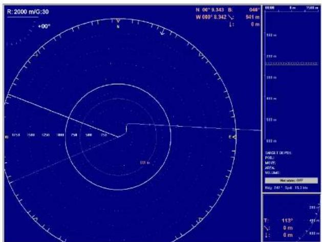
When the True Motion/Vertical mode is selected, the picture is divided into three sections; where the left side is a True motion presentation similar to the true motion presentation previously described.
Display modes
Dual 1
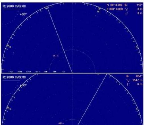
The Dual 1 mode is a kind of “two sonars in one” operation, where each presentation is updated for every second transmission. All settings can be set individually for each of the two presentations. This makes the dual mode especially useful for optimizing settings by directly comparing the two presentations.
Dual 2
The Dual 2 mode is very similar to the Dual 1 mode previously described, but the “two sonars” are presented next to each other. All settings can still be set individually for each of the two presentations.

Sonar Operating Panel
SONAR OPERATING PANEL
Introduction
You may enter operational commands directly on the Sonar Operating Panel. Sonar functions may also be accessed and activated using the menu field on the display and the trackball on the operating panel.
Frequently used functions are directly accessed by the designated control buttons. These are grouped according to their purpose.

SonarOperatingPanel
CD6377B

Main switch
Main switch functions control power to the sonar, hoisting and lowering of the transducer and indicates the transducer's current position.
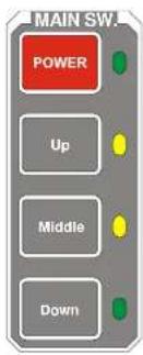
Power
Pressing Power for approximately two seconds powers up the sonar. The adjacent green LED blinks while the Sonar Control Unit boots up, and remains illuminated once the system is operational.
Before the sonar can be powered down, the transducer must be in the Up position. Pressing the Power button for approximately two seconds secures power to the unit which is confirmed by the adjacent green LED being extinguished.
Up
Raises the transducer to its upper position. The adjacent green LED blinks while the transducer is raised and remains illuminated once it is housed safely inside the hull of the vessel. The green blinking LED will also be accompanied by an audible signal.
Middle
Raises or lowers the transducer to its middle position.
The physical location of the middle position can be defined in the Transducer parameter dialogue.
Symbol
The Symbol functions provide on-screen graphic references for targets, own ship and fishing gear.

(A) Target marker
To mark a target, move the cursor over it and press the button. A triangular symbol with a corresponding number will appear on the screen over the target.
Position data for the defined markers are displayed in the Objectsmenu.
Note that the system continues to track the markers even when outside the sonar range.
The Target marker function can also be used for manual target tracking as the system is designed to calculate the speed (S), course (C) and distance (D) between the last two chosen targets.
The Target marker data is displayed in white figures for three minutes in the lower right hand corner of the horizontal presentation. This function is also an effective method for determining the distance between two selected points on the screen.
(B) Own ship marker
Seine circle
This is a useful aid in planning the shooting of the purse seine. It is used as follows:
- Press the Gear button.
- The purse seine circle will appear on the forward end of the ship symbol on the corresponding side of the vessel selected in the Setup menu. The circle will follow the vessel's movements.
- At the moment the seine is shot, press the Gear button again.
- The purse seine circle will remain stationary and indicate the ideal path for setting the seine. Three square symbols on the ship's course line indicate the: shooting, one half, and the end of the seine positions. Three different nets can be pre-programmed in the Gearmenu.
- Press the Gear button to delete the Purse Seine circle.
Trawl symbol
This is a useful aid in providing an overview of the trawl operation.
Trawl data can be set manually using the menu or automatically by interfacing the Simrad FS trawl sonar or ITI trawl monitoring system with the sonar.
- In the manual mode the trawl symbol will be displayed with the selected size, depth and distance.
Mode
The four Mode buttons can be used to select either the four favourite display modes or user settings. The set up the buttons to choose modes or settings, select Mode Buttons in the Displaymenu.
flowchart
graph TD
    A["MODE 1"] --> B["Mode 2"]
    B --> C["Mode 3"]
    C --> D["Mode 4"]
Depending on the selection you make in the Mode Buttons menu, you have two options:
- To select a mode, use the Mode button on the top of the menu, or press one of the four Mode buttons. Frequently used operational modes that are task specific to particular phases of the fishing operation can be pre-defined in the Sort modes menu. For example, Mode 1 may be used for the search phase, Mode 2 for the evaluation phase, Mode 3 for the catch phase, and Mode 4 for dual operation.
- To select a user setting, you can select User Settings on the the Setup menu, or you can use one of the four Mode buttons. The different user settings are created and maintained in the User Setting parameter dialogue. To choose user setting assignment to the four buttons, sort the list of users alphabetically.
Related topics
→ SortModes,page68
→ DisplayModes,page13
→ User Settings none 145
Gain
Gain controls are specified as either horizontal or vertical.

flowchart
graph TD
    A["Gain H-"] --> B["Gain H+"]
    C["Gain V-"] --> D["Gain V+"]
    style A fill:#f9f,stroke:#333
    style B fill:#ccf,stroke:#333
    style C fill:#cfc,stroke:#333
    style D fill:#fcc,stroke:#333
Horizontal gain
The two upper buttons control receiver gain effecting the horizontal presentation of the sonar. The level of gain selected is display in the Horizontal menu and on top of the tilt indicator in the upper left-hand side of the display. It has 51 selectable values numbered from 0 to 50 and may be changed in steps of 1 dB.
Vertical gain
The two lower buttons control receiver gain effecting the vertical presentation of the sonar. The level of gain selected is display in the Vertical menu. It has 51 selectable values numbered from 0 to 50 and may be changed in steps of 1 dB.
Range
Range controls are specified as either horizontal or vertical.
Horizontal range
The two upper buttons control the horizontal range. The range selected is displayed in the Horizontal menu, and on top of the tilt indicator in the upper left corner of the display.
Vertical range
The two lower buttons control the vertical range. The range selected is displayed in the Vertical menu.
Cursor
The cursor is used for on-screen cursor orientation and menu operation.

Menu
The Menubuttonisusedfor selection between Menu or Full Screenpresentations. When the main menu is displayed, the echo presentation will be reduced correspondingly. In full screen presentation, the full dimension of the screen is used for the echo presentation.
When the full screen echo presentation is displayed, the cursor may be used to activate the menu field by moving it to the left or right extremes of the screen. Moving the cursor outside the menu field will hide the menu.
Select
The Select button is used to execute a selection. This corresponds to the left button on a standard mouse.
View
Trackball
The trackball controls the cursor. The cursor changes appearance in relation to its location on the screen:
• An Orange cursor in the echo field.
• An arrow in the menu field.
- A negative or positive sign at each end of the menu buttons. The negative or positive sign indicates the direction in which the corresponding parameter values will be changed when the Selectbutton is pressed.
Related topics
→ Menuandfullscreenpresentations,page41
→ Viewpop-upmenu, page70
→ Objectpop-upmenu,page72
→ Menubuttons,page45
Train
The audio channel is displayed as a continuous white line. It can be trained either manually or automatically. The bearing angle is displayed in the upper right-hand corner of the display, indicated relative to the bow.

flowchart
graph TD
    A["Position Track"] --> B["Manual"]
    C["Target Track"] --> D["Auto Search"]
    E["Start"] --> F["Downward Arrow"]
    G["Downward Arrow"] --> H["Downward Arrow"]
(CD18022H)
Manual
In the Manual mode the train left (arrow) or train right (arrow) buttons are used to direct the audio line to the desired bearing.
Auto search
In the Auto Search mode the sonar will automatically search within pre-set sector limits with the selected audio line designating the centre of the search. The search sector is displayed on the bearing card with two white angular symbols.
- The search sector is adjusted by reasoning and holding the
When the Auto Tilt function is activated in the Position Track mode the tilt search centre is automatically adjusted with regard to the distance to the tracked position.
Target track
To track a target, place the cursor over the desired location and press the Target Track button. A circle will appear on the display and its position automatically tracked by the system using the strongest echo centred in the "window" represented by two lines on the audio line. The "window's" size may be selected by the Track Window button in the Setup menu.
The vector originating from the target's centre indicates its course and speed. The length of the vector increases relative to the target's speed. One knot is represented by a small mark on the vector. A course line can also be displayed showing the target's track.
Target tracking symbols and data are displayed with a light violet colour. In addition to the information on the Catch data page, the speed, course and distance for some modes are found in the lower left hand corner of the screen.
In Manual tilt mode, the tilt angle will automatically be adjusted with respect to the distance to the tracked target.
When the Auto Tilt function is activated in the Target Track mode, the tilt search centre is automatically adjusted with regard to the distance to the tracked position.
Tilt
Manual tilt
In Manual mode the transducer may be tilted within the systems limits by pressing the Tilt up (arrow) or Tilt down (arrow) buttons. Pressing either button once changes the tilt angle in steps of 1 degree. Pressing and holding either button continuously changes the tilt angle until pressure is removed.
In the Position and Target Tracking modes, the tilt angle will automatically be adjusted to compensate for the distance to the tracked position.

Auto tilt
In the Auto Tilt mode the selected tilt angle forms the centre of the tilt search. The selected tilt limits are displayed on the tilt indicator by yellow lines and corresponding numerical values for both the upper and lower limits.
The centre of the tilt search sector is adjusted by pressing the Tilt up (arrow) or Tilt down (arrow) buttons. Sector limits are adjusted by pressing and holding the Auto button and simultaneously pressing the Tilt up (arrow) or Tilt down (arrow) buttons.
Tilt search sector limits can be incremented in steps of 1 degree to 10 degrees according to the value selected in the in the Tilt
Various
The buttons grouped under various are Zoom, Record, Mute and OffCentre.

Mute
The Mute button is not used on the SH80 sonar.
Record
The record function is used for storing either a sequence or single display picture. Sequential or single storage options are preset in the Store/Recall menu (available from the Setup menu).
If sequential store mode is selected, Record is used for starting and stopping the storage. If single shot storage is selected a new picture is storage each time the button is pressed.
Zoom
The zoom function magnifies an area of the display by positioning the cursor in its centre and pressing the Zoom button. The Zoom button works as a toggle switch for on/off of the zoom function.
Off centre
The Off Centre function moves the Own vessel symbol to the cursor's position on the display. This adjusts the presentation to
OPERATION
Introduction
All operation of the sonar is normally made from the Sonar Operating Panel. Optionally, a standard mouse or trackball may be connected, and the sonar can then be operated by means of the menu system alone.
This section contains a detailed description of the start and stop procedures, the principles of the menu operation, and other operational procedures for the daily use of the SH80. In order to obtain the necessary understanding of the sonar design, refer to the System description chapter. The various presentation formats are described in the Display mode chapter.
Topics
→ Maintainingthesonar,page37
→ Startandstopprocedure.page38
→ Menuoperation,page41
→ Visualaids,page49
→ Cosmetics,page50
→ Installationofoptions,page53
→ On-linehelp,page5.5
Maintaining the sonar
Maintenance procedures
To ensure the best possible reliability of the SH80 sonar, it is important to follow the maintenance procedures described in the Maintenancechapter.
A preventive maintenance schedule is provided. It is very important that you follow this schedule, and that you log the actions thoroughly. Refer to the information in the Maintenance chapter.
Important when docking the vessel
Caution: Whendockingthevessel, disconnectthemainsplugon theSonarProcessorUnittopreventinadvertentuseof thesonar. Thetransducercanbedamagedifallowedto transmitinair.
Note: RefertotheinformationintheMaintenancechapter!
Related topics
→ Maintenance, page 150
→ Preventivemaintenanceschedule,page151
Start and stop procedures
Note: Before you start the sonar, check that the water depth this sufficient, and that the vessel's speed is within the maximum speeds specified with the transducer lowered.
Start procedure
Observe the following procedure to power up the sonar.
-
Press the Power button on the monitor to power up the display monitor.
-
Press and hold the red Power button on the Sonar Operating Panel for approximately two seconds to start the sonar.
- The green LED next to the button indicates that the sonar starts loading the program. After approximately one and a half minutes the sonar picture will be displayed.
- Press the Down button to move the transducer to the lower position.
- The green LED next to the button will flash, and an audible signal indicates that the transducer moves downwards
Disconnected mains
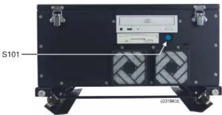
In case of power failure, or if the mains plug on the Sonar Processor Unit has been disconnected, the sonar must be started by pressing the start switch S101. This switch is located behind the small front panel on the Sonar Processor Unit.
The location of the S101 switch on the front of the Sonar Processor Unit.
Design change
On sonars shipped from Simrad before August 2003, the APC10 Sonar Processor Unit is used. This unit is also equipped with an "on/off" switch behind a front panel. It has also an additional "master on/off" switch on its rear panel. Instead of disconnecting the mains plug, this switch can be set to "off".
Stop procedure
- Press the Up button on the Sonar Operating Panel to hoist the transducer to the upper position.
The .....LED screen to the bottom will flush and
Procedures for emergency hoisting are provided in the Maintenancechapter.
Dry-docking safety measures
To prevent inadvertent use of the sonar when dry-docking etc., disconnect the mains plug for the Sonar Processor Unit.
Warning: Transmitting air will damage the transducer!
Related topics
→ SonarOperatingPanel,Mainswitch.page24
→ Manualhoistingandlowering,page162
→ Status,page134
Menu operation
Introduction
The menu system on the SH80 sonar is designed to allow for easy and fast access to the parameters.
The menu can be removed from the screen.
Some of the parameters (for example Range, Gain and Tilt) can be controlled both from the button on the menu and from buttons on the Sonar Operating Panel. The parameter values shown on the menu buttons will then change according to the setting made on the panel.
It is also possible to operate the sonar with a standard computer mouse.
Screen presentations
The menu can be set up for permanent display, or available only when required for parameter alterations. The Menu button on the Sonar Operating Panel is used to select Menu or Full Screenpresentation.
Menu presentation
In Menu presentation, the menu is always shown on the right hand side of the display, and the size of the echo area will be reduced.
Typicalscreen presentationwith themenonthe righthandside

Operation
Fullscreen presentationwith themenuhidden fromview

Fullscreen presentationwith temporarymenu

Menu structure
The menu field on the sonar display contains several different buttons, tabs and parameter dialogues.

(A)Sonartype: The upper "button" indicates the sonar in operation. You can not press this button.
(B) Modeselection: The second button is used to display the current mode. You can press this button to select a different mode.
(C) Tabs: These selections on the right hand side of the menu allows you to choose between the menus applicable for the current operational mode. The menu field will provide different tabs for each display mode. In order to select a new menu, move the cursor to the tab, and press Select.
(D)Activemenu:The next field contains the main menu. Depending on operational mode and the menu properties, this menu can contain a number of buttons or other information.
(E)Menubutton: Each menu button allows you to define the parameters for the specific function.
Menu buttons
Each menu contains several buttons. Each button shows both the function and the current parameter. The majority of the buttons in each menu field have three functions.
• You can select a lower parameter value.
• You can select a higher parameter value.
- You can open the applicable dialogue.

flowchart
graph TD
    A["Gain: * 30"] --> B["-"]
    B --> C["A"]
    C --> D["C"]
    D --> E["B"]
    E --> F["+"]
(A) Decrease: Position the cursor on the left side the button. Observe the arrow symbol change to a minus sign: Decrease the parameter by pressing the Select button.
(B) Increase: Position the cursor on the right side the button. Observe the arrow symbol change to a plus sign: Increase the parameter by pressing the Selectbutton.
(C) Dialogue: Position the cursor on the centre of the menu button. Observe the arrow symbol change to a menu symbol. Open the parameter dialogue by pressing the Select button. The dialogue appears in the lower part of the menu field,
Selecting a new parameter value
The menu system is operated by the trackball and the Select button on the Sonar Operating Panel.

When you have gained more experience, and have become more familiar with the available options, you will select the parameters directly from the "smart" buttons. Use the trackball to move the cursor, and position it over the button.
First method:
-
Use the trackball to move the cursor to the right or left side of the button. Observe that the cursor symbol changes.
-
Increase or decrease the option by pressing the Select button (A).
Second method:
-
Use the trackball to move the cursor to the middle of the button (B). Observe that the cursor symbol changes to a small menu icon.
-
Click the Select button (A) on the Sonar Operating Panel. Observe the parameter dialogue appearing at the bottom of
Operation
The parameter value shown in the button is operational even without closing the parameter dialogue. This makes it easy to test the effect of each parameter setting. Note that the transceiver related parameters will first be in operation in the next ping.
Stored parameters
Default settings
The parameter settings identified with an asterisk (*), indicates the normal setting known to perform well under normal conditions. If you get "lost" in the parameter settings, the Default settings function will bring up these normal parameters.
The Default setting function is available on the Setup menu, and a dedicated parameter dialogue is used.
User settings
The User setting function allows you to store chosen parameter settings for various types of fisheries, or your favourite individual settings. The saved settings can easily be retrieved into the operational sonar.
The User setting function is available on the Setup menu, and a dedicated parameter dialogue is used.
Parameter memory
The SH80 sonar is equipped with a battery powered memory. This function will cause the sonar to remember all the selected parameter settings, even when the sonar is switched off.
Related topics
→ DefaultSettings.page96
Visual aids
Common information on the display
In nearly all display modes, the following information is provided.
- The Tilt indicator is displayed in the upper left corner. The selected range and gain is shown on top of this indicator.
- The orange text in the upper right hand corner of the echo area shows the bearing, distance and depth of the cursor.
- If a GPS is connected to the sonar, the geographical latitude and longitude for the cursor location will also be displayed.
![B R=1000×N×30 A N 00° 0.642 B: 355 W=00° 0.050 L: 197 m L: 0 m C D [00° N]](/content/2026/05/925539/images/c6d1bab2754d44697ddb56b1a5a231f607054d93fec4a7ab9371ac5194eb3888.jpg)
(A)Tiltindicator
(B) Selected range and gain, and current usersetting (ifused)
(C)Geographicalposition
Cosmetics
Sonardisplaywith BearingCard(A) WindMarker(B) andDistanceRings (C) enabled
The choices in the Cosmetics menu allows you to enable or disable a range of visual aids in the sonar picture.

(A) The Bearing Card shows the current bearing relative to the
Operation
Sonardisplaywith VariableRange Marker(D), Compass Card(E)andVertical Ring(F)enabled. TheVerticalRing reflectsthevertical rangesetting.

(D) The VRM (Variable Range Marker) consists of an adjustable range ring with range readout. It can be used for any
Sonardisplaywith VerticalDepth dividers(G),Track historywithMinute Markers(H)and BowMarker(I) enabled.

(G) The Depth dividers are horizontal dotted lines used to visualize the depth steps in the vertical slices.
(H) The Minute markers are shown as small circles on the track history of the ship.
Installation of options
The following options can be installed on the SH80 sonar:
• Triple- or multiple-frequency
• Scientific output
Note that all options are pre-programmed into the standard sonar version, and that Simrad offer a 1 month free test period for certain options. When ordering a permanent option installation, a code word will be released from Simrad.
For a free test, or permanent option installation, use the following procedure:
-
Select the Setupmenu.
-
Press the Test button to activate the System test menu.
- Press the Installation Menu button.
- Observe that the installation menu bar is shown on the top of the screen.
Installation I/O Setup OwnShip Environment Options
- Press Options on the menu bar.
- Select Install Options to activate the Install options parameter dialogue.
Install Options
HWID: 00047624fed4
Note: If any time ordate adjustments are made during the test period, the option will be closed.
Add License String - This button is used for permanent installation of the chosen option. When you press the button, this will activate the On-Screen Keyboard used to type the required 32-character code word.
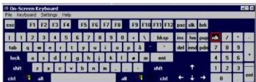
Procedure:
- Press Add License string.
- Place the cursor in the text field.
- Type the code word.
- Check that the 32 characters is entered correctly into the text field
- Press the Apply License String button.
On-line help
The SH80 sonar is equipped with a comprehensive on-line help system. It is available from all the parameter dialogues and menus by pressing the Help button.
Help is provided in two levels: On-line and Free.
Once pressed, the first Help text will appear in the bottom of the menu. This is the On-line text. It is short, context sensitive, and designed not to interrupt the operation of the sonar. To close the Help dialogue, press the Close button.
To access more detailed information, press the Free button. This will open the complete interactive manual. It contains the same information as the printed Operator manual, but the information is accessed using the menu on the left hand side and interactive links throughout the document.
Press Free in the bottom left corner to return to the small On-line dialogue, or Close to exit the interactive manual.
Note that if you press Close, the large interactive manual will automatically reappear the next time you press a Help button.
MENU DESCRIPTIONS
Introduction
This section provides a detailed description of the complete menu system for the SH80 sonar, and contains the chapters listed below. For an explanation of how to operate the menu system, refer to the section Menu operation.
The SH80 comprises a large number of different menus on several levels. Menus are selected by pressing their respective tabs on the right side, and the appearance of menus and tabs depends on the chosen operation mode and the current settings. The menu types are organised as follows:
• Active menus - relevant for each of the display modes, available at all times selectable by the appropriate tab.
- Temporary menus - "sub-menus" activated by a button in one of the Active menus.
- Pop-up menus - activated by the View and Object buttons on the Sonar Operating Panel, or the middle and right mouse button (provided a mouse is installed).
• View menus - activated in the View pop-up menu.
- Messages - presents system messages.
Topics
A 1
Active menus
Overview
The Active menus are those relevant for the different operational modes. The menus are shown with vertical selector tabs on the right hand side, and each menu can easily be selected using the trackball and the Select button on the Sonar Operating Panel. All menus have access to on-line help through a Help button.
Topics
→ Horizontal, page 58
→ Vertical,page59
→ Display,page60
→ Setup,page61
→ Objects,page62
Horizontal
The Horizontalmenu is used to control the horizontal presentations. The parameters chosen are present in all display modes. When a horizontal parameter setting is selected and defined in one mode, the chosen settings will automatically be applied to all modes.
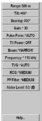
Parameters
→ Range,page121
→ Tilt,page137
→ Bearing.page88
→ Gain,page105
→ PulseForm,page119
→ TxPower,page143
→ Beam,page86
→ Frequency,page104
→ TVG(TimeVariableGain),page142
→ RCG(ReverberationControlledGain),page123
→ PPFilter,page118
→ NoiseLevel,page115
The Help button opens the on-line help.
The Horizontal 2 menu is identical to the Horizontal menu. It
Vertical
The Verticalmenu is only shown in modes with a vertical slice function. All relevant settings, except the TXPower, can be selected separately for the vertical modes independent of the horizontal settings. When any vertical setting is selected and defined in one mode, the setting will be applied to all vertical modes.
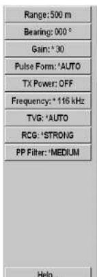
Parameters
→ Range,page121
→ Bearing(Vertical),page91
→ Gain,page105
→ PulseForm,page119
→ TxPower,page143
→ Frequency.page104
→ TVG(TimeVariableGain),page142
→ RCG(ReverberationControlledGain),page123
→ PPFilter,page118
The Help button opens the on-line help.
Display
The Displaymenuisshowninalldisplaymodes, and provides access to parameters controlling the visual presentation of the sonarviews. Some of the choices on themenuaresimpleon/off buttons.
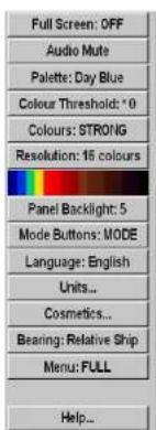
Parameters
FullScreen-ReplicaoftheMenubuttonontheSonar OperatingPanel.
Audio Mute - Replica of the Mute button on the Sonar OperatingPanel.
Resolution-Select16or64coloursinthedisplaypresentation. Thechosenresolutionisshowninthecolourbarbelowthe button.
→ Palette,page116
→ ColourThreshold,page92
→ Colours,page93
→ Panelbacklight,page117
→ Modebuttons.page113
→ Language,page109
→ Units,page144
→ Cosmetics,page64
-
-
-
-
-
-
-
-
-
-
-
-
-
-
-
-
-
-
-
-
-
-
-
-
-
-
-
-
-
-
-
-
-
-
-
-
-
-
-
-
-
-
-
-
-
-
-
-
-
-
-
-
-
-
-
-
-
-
-
-
-
-
-
-
-
-
-
-
-
-
-
-
-
-
-
-
-
-
-
-
-
-
-
-
-
-
-
-
- 90.
-
-
-
-
-
-
-
-
-
-
-
-
-
-
-
-
-
-
-
-
-
-
-
-
-
-
-
-
-
-
-
-
-
-
-
-
-
-
-
-
-
-
-
-
-
-
-
-
-
-
-
-
-
-
-
-
-
-
-
-
-
-
-
-
-
-
-
-
-
-
-
-
-
-
-
-
-
-
-
-
-
-
-
-
-
-
-
Setup
The Setup menu is shown in all display modes, and gives access to parameters controlling the processing and algorithms in the sonar system. It also provides access to specific system parameters and functions such as Test and Store/Recall.
| StoreRecall... |
| Test... |
| Gear: $ Bottom Trawl |
| School: CAPELIN |
| Dead Reckoning: OFF |
| Stabilizer: OFF |
| Movements: * 3 min |
| Track Window: MEDIUM |
| Wind Direction: 023° |
| Sort Modes... |
| External Sync... |
| Scientific Output... |
| Fish Alarm... |
| User Setting... |
| Default Setting... |
| Help... |
Setup
Parameters
→ Store/Recall,page65
→ Test,page66
→ Gear,page106
→ School,page127
→ Deadreckoning,page95
→ Stabilizer, page 133
→ Movements,page114
→ TrackWindow,page140
→ Winddirection,page146
→ Windspeed,page147
→ SortModes,page68
→ ExternalSync,page102
→ ScientificOutput,page128
→ FishAlarm,page103
→ UserSetting,page145
Objects
The Objects menu is shown in all display modes, and displays the range (R), bearing (B) and depth (D) to all selected objects.
![ID R[m] B[°] D[m] AT 1 1002 061 0 CI 891 062 0 M 1 563 049 0 OS 44 160 0 PT 650 031 0 Delete Delete All Help...](/content/2026/05/925539/images/9f64bffa8592f6510b09f447dad115be1264713bfa3856fabf71cb2ca2a743ab.jpg)
The identification (ID) abbreviations for the different objects are:
AT - Automatic Target Track Marker
Ci- Circle Marker
M- Target Marker
OS- Own Ship Marker
PT - Position Track Marker
F - Radio buoy marker (if a GPS buoy system is connected)
The number behind the ID abbreviation refers to the same number on the object in the sonar presentation. The P after the Automatic Target Track Marker indicates the priority level where the audio channel is locked to the target.
When selecting an object in the list, a list with all the available object data will be shown below the Objects menu.
When selecting a Target Marker, Automatic Target Track Marker or a Radio Buoy Marker in the list, a dotted bearing line from the vessel to the marker will be presented.
To delete an object, select the relevant marker in the list, and press the Delete button in the lower part of the menu. Pressing
Temporary menus
The Temporary menus are those selected from the active menus. They are also shown with vertical tabs on the right side of the menu, and can easily be selected by the trackball and the Select button. The Temporary menus must however be removed manually using the Close button in the bottom of menu. All Temporary menus have access to on-line help through a Helpbutton.
Topics
→ Cosmetics,page64
→ Store/Recall,page65
→ Test,page66
→ SortModes,page68
Cosmetics
The Cosmetics menu is activated by pressing the Cosmetics button in the Displaymenu. It provides access to various parameters controlling the appearance of the sonar picture. All the functions - except Track history - are on/off buttons.

Parameters
→ SlantRange/TrueRange,page131
→ BearingCard,page50
→ CompassCard,page51
→ DistanceRings,page50
→ VRM(VariableRangeMarker),page51
→ BowMarker,page52
→ TrackHistory;page139
→ MinuteMarker.page52
→ Wind Marker, page 50
→ VerticalRing,page51
→ Depthdividers.page52
The Close button closes this menu. The Help button opens the on-line help.
Store/ Recall
The Store/Recall menu is activated by the Store/Recall button in the Setupmenu.

The Store/Recall menu is used to store single display pictures or a sequence or pictures. The stored pictures can easily be recalled for evaluation or comparing schools.
Parameters
Store - This is the "record" button to start the storage sequence.
Delete - Deletes the highlighted display picture.
Rename-Provides an on-screen keyboard to rename the stored picture.
Print-Allows you to print the stored picture to the default printer (if any).
The following other parameters are available:
→ Store,page135
→ StoreMode,page135
→ Recall,page124
→ RecallMode,page124
The Close button closes this menu. The Help button opens the on-line help.
System test
The System test menu is activated by the Test button in the Setupmenu.
The System test menu provides several test routines available to perform operational and functional tests. These tests are designed only to be carried out by qualified service engineers.

Parameters
Test Configuration - This function is only to be activated by qualified service engineers.
Test Function - This function is only to be activated by qualified service engineers.
Toggle TxPower - This function is only to be activated by qualified service engineers.
Test Beam - This function is only to be activated by qualified service engineers.
Echo Level - This button provides a readout of the current noise in the waters surrounding the vessel. This noise is caused by air bubbles, water flow and mechanical disturbances from hull and engine. In order to obtain the best possible sonar result, the noise level readout should be as close to 0.0 dB as possible.
_1 _2 _3 _4 _5 _6 _7 _8 _9 _10
About - This button provides access to a small information dialogue providing the current software version.
The Close button closes this menu. The Help button opens the on-line help.
Related topics
→ Messagebar,page111
→ About,page85
Sort Modes
The Sort Modes menu is activated by the Sort Modes button in the Setupmenu.
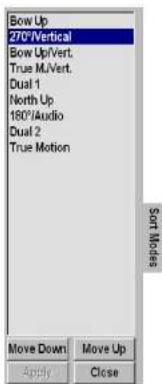
The Sort Modes menu is used to select the display modes to be activated by the four Mode buttons on the Sonar Operating Panel. The four upper display modes in this menu will always be the four modes selectable by the four Mode buttons in the order they are sorted.
In order to sort the modes, select the actual mode and use the Move Up and Move Down buttons to place it in the wanted position.
When the modes are organized in the requested order, press the Apply button to store the information.
Related topics
→ Modebuttons,OperatorPanel,page27
→ Modebuttons.page113
Pop-up menus
The pop-up menus are accessed using the View and Object buttons on the Sonar Operating Panel, or the middle and right mouse buttons if an optional mouse is installed. Each button will present a small menu, and it appears at the cursor's current location. To make a selection, use the trackball and the Select button, or the mouse.
Topics
→ View,page70
→ Object,page72
Related topics
→ ViewandObjectbuttons,page30
View pop-up
The View pop-up menu is accessed using the View button over the trackball on the Sonar Operating Panel or the middle mouse button if an optional mouse is installed.
Set New Display Centre
Ship to Center
Zoom
Erase Echoes
Synchronize
Make Same Size
Gray scale data
View Menu..
When activating the pop-up menu in the Catch Data view, it will display the following reduced menu.
Erase Echoes
Make Same Size
Gray scale data
View Menu..
Parameters
Grey scale data - This command changes the display from a colour presentation to a black-and-white. The number of shades of grey and the number of different colours used will be the same. The Greyscaledatacommand can be selected for singular sonar views independent of each other.
View Menu - When this function is selected menus will be displayed according to the view in which the cursor is situated. Several different View menus are available.
Related topics
→ Viewmenus,page74
→ Setupmenu,page61
→ Viewbutton, page30
Object pop-up
The Object pop-up menu is accessed using the Object button over the trackball on the Sonar Operating Panel, or the right mouse button if an optional mouse is installed.
| Target Track |
| Position Track |
| Set Marker |
| New Own Ship Marker |
| Circle Marker |
| New Ruler |
| Gear Symbol |
This pop-up menu is mainly used when you operate the sonar from an optional mouse, as most of the functions on it can be selected directly on the Sonar Operating Panel. Note that the cursor related selections in the Object pop-up menu use the cursor position where the pop-up menu was activated.
Activating the Object pop-up menu whilst positioning the cursor over a defined object on the display, it will display the following additional parameters.
- Inspect
- Delete
• Make
Parameters
Basic functions - These choices provide the same functions as their respective buttons on the Sonar Operating Panel.
- Target Track
- Position Track
- Set Marker
- Circle Marker
- Gear Symbol
- New Own Ship Marker
New ruler - When this function is selected, a straight line is drawn from the current cursor position (where the Object pop-up menu was selected) to another selectable position. The ruler will display range and bearing between the two points. To remove the ruler, click on it with the right mouse button, and select Remove ruler from the Object pop-up menu.
Inspect ruler - If you click on an existing ruler, the Ruler parameter dialogue will appear under the menu. This dialogue will provide information about the selected ruler, and it allows you to remove the ruler with a Delete button.
Inspect
Delete
View menus
The View menus are activated from the View pop-up menu, which again is accessed using the View button on the Sonar Operating Panel or the middle mouse button. The View menus are shown with vertical tabs on the right hand side, and the menus can easily be closed using the Close button in the lower part of each menu. All menus have access to on-line help through a Helpbutton.
Topics
→ GeoView,page75
→ VerticalView,page76
→ CatchView,page77
Related topics
→ Viewpop-upmenu, page70
→ Viewbutton,page30
GeoView
The GeoView menu is activated by pressing the View button on the Sonar Operating Panel or the middle mouse button in any horizontal view, and then selecting View menu in the View pop-up.
The GeoViewmenu provides control of selected parameters related to the current data displayed in the horizontal view; Scale and Target track. It also provides you with a button to reposition the vessel symbol.

Parameters
Ship to centre - Moves the ship symbol to the centre of the view.
→ Scale,page126
→ TargetTrack.page136
The Close button closes this menu. The Help button opens the on-line help.
The GeoView2 menu is also available. This is identical to the GeoView menu, and used during dual mode operations.
Related topics
→ Viewpop-upmenu,page70
→ Viewbutton.page30
VerticalView
The VerticalView menu is activated by pressing the View button on the Sonar Operating Panel or the middle mouse button while positioning the cursor in any of the vertical views, and then selecting View menu in the View pop-up.
The VerticalView menu provides control of selected parameters related to the current data displayed in the vertical view; Zoom, Zoom Scale and Data Source.

Parameters
→ Zoom,page148
→ ZoomScale, page149
→ DataSource, page94
→ DirectionIndicator,97
Note that Direction Indicator is only available when Indicator is selected in the Data Source menu.
The Close button closes this menu. The Help button opens the on-line help.
Related topics
→ Viewpop-upmenu,page70
→ Viewbutton,page30
CatchView
The CatchView menu is activated by pressing the View button on the Sonar Operating Panel or the middle mouse button while the cursor is located in the Catch view, and then selecting View menu in the View pop-up.
The Catch view is only available in the 270°/Vertical, True Motion/Vertical and Bow up/Vertical display modes, and you may need to hide the menu to see it.
The CatchViewmenu provides control of selected parameters related to the current data displayed in the Catch view.

Parameters
→ Range,page122
The Close button closes this menu. The Help button opens the on-line help.
Related topics
→ Viewpop-upmenu,page70
→ Viewbutton, page30
Messages
Message categories
When necessary, the sonar will provide you (or your service engineer) with operational and technical messages. These messages are sorted into four categories; Warnings, Operator alarms, System alarms and Errors.
In order to access the messages, the Message bar must be enabled. This function can be set to activate itself when necessary. The Message Bar is located at the bottom of the display, and it contains four buttons, one for each category of messages. These buttons give an overview of the number of unread messages currently in the system. Each of the four buttons gives access to a dialogue where each message can be read, acknowledged and deleted. Whennomessagesare present, the four buttons are grey. When one or more unread messages exists, the Warning and Operational Alarm buttons are yellow, while the System Alarm and Error buttons are red.

Topics
→ Warnings,page79
→ Operatoralarms, page80
→ Systemalarms,page81
Warnings
The Warnings menu is activated from the Warnings button in the Messagebar.
The Warningsmenu displays the warning messages issued by the sonar. Each warning is identified with time of issue and aheading. Additional information is found in the small text field below the message list. The top of the message list with the most recent messages is always displayed when the dialogue is opened. Acknowledged messages are displayed in grey.
Use the trackball and select individual messages with the Select button on the Sonar Operating Panel.

Parameters
Ack(knowledge) - Press this button to acknowledge the selected message.
Delete - Press this button to delete the selected message.
The Close button closes the menu. The Help button opens the on-line help.
Related topics
→ MessageBar.page111
→ TrackballandSelectbutton,page30
Operator alarms
The Operator alarms dialogue is activated from the Op.Alarmsbutton in the Messagebar.
The Operatoralarmsmenu displays the alarms issued by the sonar. Each alarm message is identified with time of issue and a heading. Additional information is found in the small text field below the message list. The top of the message list with the most recent messages is always displayed when the menu is opened. Acknowledged messages are displayed in grey.
Use the trackball and select individual messages with the Select button on the Sonar Operating Panel.

Operator Alarm parameters
Ack(knowledge) - Press this button to acknowledge the selected message.
Delete - Press this button to delete the selected message.
The Close button closes the dialogue. The Help button opens the on-line help.
Related topics
→ MessageBar.page111
→ TrackballandSelectbutton,page30
System alarms
The System alarms dialogue is activated from the Sys.Alarms button in the Messagebar.
The Systemalarmsdialogue displays the alarms issued by the sonar. Each alarm message is identified with time of issue and a heading. Additional information is found in the small text field below the message list. The top of the message list with the most recent messages is always displayed when the dialogue is opened. Acknowledged messages are displayed in grey.
Use the trackball and select individual messages with the Select button on the Sonar Operating Panel.
Parameters
Ack(knowledge) - Press this button to acknowledge the selected message.
Delete - Press this button to delete the selected message.
The Close button closes the dialogue. The Help button opens the on-line help.
Related topics
→ MessageBar.page111
→ TrackballandSelectbutton,page30
Errors
The Errors dialogue is activated from the Errors button in the Messagebar.
The Errorsmenu displays the alarms issued by the sonar. Each error message is identified with time of issue and a heading. Additional information is found in the small text field below the message list. The top of the message list with the most recent messages is always displayed when the menu is opened. Acknowledged messages are displayed in grey.
Use the trackball and select individual messages with the Select button on the Sonar Operating Panel.

Parameters
Ack(knowledge) - Press this button to acknowledge the selected message.
Delete - Press this button to delete the selected message.
The Close button closes the dialogue. The Help button opens the on-line help.
Related topics
→ Message Bar, page 111
→ Trackball and Select button, page 30
PARAMETERS
About parameter dialogues and help
This chapter describes all the parameter dialogues accessed from the menu system.
When a parameter is selected, the available choices are shown in the dialogue below the menu. The setting is then made using the available buttons or lists. Several levels are frequently used to select the parameters.
Note that:
- In many cases you will not need to open the parameter dialogue, as you can control the settings directly on the menu button.
- The parameter is selected and activated by the sonar once it is highlighted in the dialogue. The operational changes can thus be investigated from within the dialogue without closing it.
- The Close button will always close the dialogue.
- The Help button will always provide short-form context sensitive help. This help text will appear on top of the parameter dialogue, and you need to press Close to return.
In the Help window, you can also press Free to access to full interactive manual. This may not be available in all
Alphabetical list
The following is an overview of available parameters incorporated in the SH80 sonar system.
→ About,page85 → RCG,page123
→ Beam,page86 → Recall,page124
→ Bearing,page88 → RecallMode,page124
→ Bearing(Display),page90 → Ruler,page125
→ Bearing(Vertical),page91 → Scale,page126
→ ColourThreshold,page92 → SchoolData,page127
→ Colours,page93 → ScientificOutput,page128
→ DataSource, page94 → SearchSector, page129
→ Dateandtime,page138 → SearchStep,page130
→ DeadReckoning,page95 → SlantRange,page131
→ Defaultsetting,page96 → Speed,page132
→ DirectionIndicator,page97 → Stabilizer,page133
→ Editgear(Purse),page98 → Status,page134
→ Editgear(Trawl),page99 → Store,page135
→ Editschool,page101 → StoreMode,page135
→ Externalsynchronisation,page102 → TargetTrack,page136
→ Fishalarm,page103 → Tilt,page137
→ Frequency, page104 → Timeanddate, page138
→ Gain,page105 → TrackHistory,page139
→ Gear,page106 → TrackWindow,page140
Parameters
About
The About parameter dialogue is accessed from the System test menu.

The About dialogue is only used to provide information about the current software version. In addition, the Versions button opens a small text document with detailed version information. This information is not intended for operational use.
Beam
The Beam parameters are accessed from the Horizontal menu.

TheBeamcommand enables you to select the vertical beam width in the horizontal presentation. The beam selection can be made manually, or controlled automatically by the selected range.
The Wide beam is designed to be used with shorter ranges in order to obtain a larger vertical coverage. This makes the sonar less "tilt dependent" in the catching phase.
The Normal beam is designed to be used for the medium ranges.
The following buttons can be used.
Wide - This button is used to select the upper range for the wide beam width in Auto mode. For ranges higher than this selection, the beam will automatically switch to Normal or Narrow, depending on the current selection for the Normal button.
Normal - This button is used to select the upper range for the normal beam width in Auto mode. For ranges higher than this selection, the beam will automatically switch to Narrow, which is indicated by a grey and unoperable Narrow button.
Bearing (Horizontal)
The Bearing parameters are accessed from the Horizontal menu.
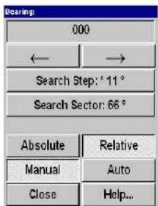
The Bearing of the audio channel is normally controlled from the Sonar Operating Panel. The selected bearing is shown with a continuous white line pointing out from the transducer position. This line can be trained manually or automatically in any position. The anglercadout on the bearing button can be selected to be ±180 degrees relative to the bow, or absolute (relative north).
Left/ Right arrow
Click to train the audio channel one dares. The current hearing
Absolute/ Relative
Click Absolute to set bearing of the audio channel to be relative to true north. Click Relative to set the bearing to be relative to the vessel's bow.
Manual/Auto
In Manual mode, the audio channel can be trained continuously in either direction by pressing the two arrow buttons in the
Train field on the Sonar Operating Panel. In Auto mode, the sonar will automatically perform search within the selected Search Sector using the steps defined.
More information about the Auto Search program are provided in the Sonar Operating Panel description.
Related topics
→ AutoSearch,page32
→ SearchStep,page130
→ SearchSector,page129
Bearing (Display)
The Bearing button is located in the Display menu.
This is simply a selector switch. Click on the button to select True north or Relative ship. Certain bearing data will change their values accordingly.
Bearing: True North
Bearing: Relative Ship
The following bearing data will change when you switch between the two settings:
- Cursor bearing
- Markers bearing in the Objects menu
• Target positions in the catch data views
Note that there are no indication on any of these readouts to identify them as relative or true.
All other bearing data remain permanent, and will not change when you select relative or true bearing.
• Wind direction - always relative to true north
- Audio line - always relative to the ship's heading
- Ship's current heading - always relative to true north
Parameters
Bearing (Vertical)
The Bearing (Vertical) parameter is accessed from the Vertical menu.

This dialogue allows you to train the audio channel bearing manually. The Bearingoftheaudiochannelisnormallycontrolled with the Train buttons on the Sonar Operating Panel. The bearing of the vertical slice, which is presented by the white audio line in the horizontal picture, may also be trained by the Bearing button in the Horizontal menu.
The following options are available:
- (minus button) - Train left.
Colour Threshold
The Colour Threshold button is located on the Display menu.

The Colour Threshold function is used to reduce the number of echo colours on the display.
The strength of the echoes is indicated with a scale of 16 or 64 colours. A weak echo has a cold colour (blue), medium echoes have warmer colours (green, yellow) and strong echoes are shown with the warmest colours (orange, red). If desired, the number of colours may be reduced. When you do this, the sonar will start with the colour indicating the weakest echoes. Therefore, by reducing colours, the maximum detection range will be reduced, because all echoes will normally appear as
Parameters
Colours
The Colours button is located in the Display menu.

The colour strength of the echo presentation can be selected with three different colour scales. Under normal conditions, the Normalcolours will give the best dynamic in the echo presentation, while Strongcolours are preferred for weaker echoes.
Do not confuse this parameter with the Colour Threshold setting.
Related topics
→ ColourThreshold, page92
Data Source
The Data Source button is located in the Vertical View menu.
The Vertical View menu is are activated by pressing the View button on the Sonar Operating Panel (or the middle mouse button) while positioning the cursor in any of the vertical views, and then selecting View menu on the View pop-up menu.

The Data Source parameter is used to select the bearing source of the vertical views.
Audio - The vertical slice will follow the trainable audio channel.
Indicator - The bearing of the vertical slice can be adjusted
Dead Reckoning
Dead Reckoning is accessed from the Setup menu.
Dead Reckoning is used to improve the position of the historical track line from the vessel, relative to the actual position of the drifting fishing gear.
Dead Reckoning: OFF
When OFF, the vessel movement and track line will be calculated from the GPS data, which then will be relative to the bottom.
Dead Reckoning: ON
When ON, the gyro and speed log are used to positioning the vessel relative to the water.
In order to get correct dead reckoning, a doppler speed log must be connected to the sonar.
Default Setting
Default Setting is accessed from the Setup menu.

This function makes it possible to delete all the parameters currently saved in the sonar's memory, and re-install thosedefined by Simrad instead; the factory default settings. These default settings are identified with an asterisk in the different parameter dialogues and menus, and will perform well under normal conditions.
Parameters
Direction Indicator
The Direction Indicator is accessed from the Vertical View menu when Data Source is set to Indicator.
The Vertical View menu is activated by pressing the View button on the Sonar Operating Panel (or the middle mouse button) while positioning the cursor in any of the vertical views, and then selecting View menu on the View pop-up menu.

This feature allows you to train the vertical slices independent of the audio channel. The Direction Indicator is shown in the horizontal presentation as a yellow dotted line.
Related topics
Edit Gear (Purse)
The Gear parameter dialogue is accessed on the Setup menu. Each of the available options in the Gear dialogue can be edited using the Edit button. When a purse has been selected, this parameter dialogue is provided.

These parameters allows you to define the depth and the length of your pursescine, as well as which side of the vessel is positioned.
Depth
This function allows you to enter the depth of your purse seine. When the Gear symbol is selected, the depth of the purse seine will be shown on all vertical views.
Edit Gear (Trawl)
The Gear parameter dialogue is accessed on the Setup menu. Each of the available options in the Gear dialogue can be edited using the Edit button. When a trawl has has been selected, this parameter dialogue is provided.

These parameters allows you to monitor or define the distance and depth of your trawl, as well as the height and width of your trawl opening. If you use the Simrad ITI system, these parameters will be provided automatically.
Distance
A dedicated parameter dialogue is provided to define the
Width
A dedicated parameter dialogue is provided to define the width of the trawl opening. The setting is made automatically if you click the Auto button, provided that a Simrad trawl system is connected to the sonar. If you click Manual, you can define the setting in steps of 10 meters.
Length
A dedicated parameter dialogue is provided to define the length of the trawl symbol on the sonar display.
Related topics
→ Gear,page106
Edit School
The Edit School parameter dialogue is accessed from the School button in the Setup menu. In the School dialogue, select species and press Edit. The top button displays the fish species selected in the Schooldialogue.

The EditSchooldialogue displays the species of fish and its presently selected density. The density for the school volume estimation is based on kg/m2 school area. The default value is 25 kg/m2 for all species, and you may adjust this figure individually in the Density parameter dialogue accessed by the Density button.
Related topics
External Synchronization
The External Sync button is located in the Setup menu.

The Externalsynchronization function makes it possible to eliminate interference from other Simrad sonars on board the vessel. If the sonars are connected together, you can use these settings to synchronise their transmissions.
Sync mode
A dedicated parameter dialogue opens. It allows you to select one of the three synchronization modes; None, Slave or Master.
- None disconnects the SH80 from the synchronisation system. The sonar will then operate completely on its own.
Fish Alarm
The Fish Alarm button is located in the Setup menu.

The Fish Alarm function makes it possible to set up the sonar to warn you when a school of fish are detected inside the selected sector. The selected sector is displayed with white dashed lines in the horizontal sonar picture.
Fish alarm
This is an on/off switch used to activate or deactivate the fish alarm function.
Start range
This button opens a dedicated dialogue in which you can select the range for the alarm sector to start; the inner radius. The start range can be selected between 0 and 7900 meters.
End range
This button opens a dedicated dialogue in which you can select the range for the alarm sector to end; the outer radius. The end range can be selected between 100 and 8000 meters.
Width
This button opens a dedicated dialogue in which you can select the width of the alarm sector. The sector width can be set
Frequency
The Frequency parameters can be called from the Horizontal and Verticalmenus.
Note that this parameter dialogue is optional, it will only be available if the triple or multiple frequency option has been installed on the sonar.

The Frequency parameter dialogue is used to select the transmitter and receiver frequency. In addition to the standard frequency, an optional multiple frequency version is available.
If multiple frequencies are installed, they are mainly intended for suppression of interference from other hydroacoustic equipment. However, the sound absorption in salt water
Parameters
Gain
The Gain is accessed from the Horizontal and Vertical menus.

The Gain is normally selected from the Sonar Operating Panel. It has 51 values, these are numbered from 0 to 50. The receiver gain is changed 1 dB per step. In addition to the readout on the Gain button, the horizontal gain is normally repeated over the tilt indicator in the upper left hand corner on the display. The default value is 30 dB.
Related topics
→ SonarOperatingPanel:Gain,page25
Gear
The Gear button is located in the Setup menu.

The Gear parameter dialogue is used to select the type of fishing gear, and together rightsize and position of the gear on the display.
By using Edit... it is possible to program the system for three different purse seines, three different bottom trawls, and three different pelagic trawls.
Related topics
→ EditGear(Purse),page98
→ Editgear(Trawl),page99
Parameters
Heading
The Heading parameter is accessed by pressing the Hdg (Heading) button in the Status dialogue at the bottom of the menus.
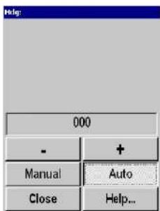
The Heading readout is a repetition of the connected course gyro input. Manual heading input may be used if signals from external sensors are missing. By selecting Manual, the + and - buttons can be used to alter the heading value.
Important: Thisreadoutmustnotbeusedfornavigation.
Inspect Object
The Inspect Object parameters are either accessed when you select a target marker in the Objects menu, or when you place the cursor on the marker and pushes the Select button on the Sonar Operating Panel.

The Inspectobjectparameter dialogue displays the current parameters for the chosen object. Note that every parameter may not be applicable for all marker categories.
The following parameters are shown:
- Depth
- Distance
- Bearing (B)
Parameters
Language
The Language button is located on the Display menu.
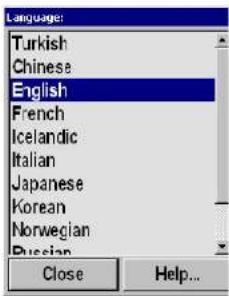
The Language parameter dialogue is used to select the language on the menus.
Menu
The Menu button is located in the Display menu.

The Menuparameter is used to select different levels of complexity of the menu system.
- For simplified use, select the Short menu system. Only the most important parameters will then be shown in the menus.
- For normal operation, select Normal. This setting is recommended for most users after some experience with the sonar.
- For advanced use, select Full. All parameters in the menus will be shown.
Parameters
Message Bar
The Message Bar button is located in the System test menu. This menu is accessed by pressing the Test... button on the Setupmenu.

The sonar automatically issues messages when a disturbance occur. The messages are grouped into four categories; Errors, System alarms, Operational alarms and Warnings. The Message Bar parameter dialogue is used to select at which level warnings and alarms shall be presented.

The Message Bar is located at the bottom of the display, and it contains four buttons, one for each category of messages. These buttons give an overview of the number of unread messages currently in the system. Each of the four buttons gives access to a menu where each message can be read, acknowledged and deleted. Whennomessagesarepresent,thefour buttonsaregrey. When one or more unread messages exists, the Warning and Operational Alarm buttons are yellow, while the System Alarm and Error buttons are red.
When no messages are present, the four buttons are grey. When one or more unread messages exists, the Warnino and
Mode
The Mode button is located on the top of every menu.
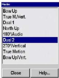
The Mode parameter dialogue is used to select display mode. It will automatically provide a selection between them, currently available on the sonar.
The various dipslay modes are described in the Display Modes chapter.
The modes can also be selected with the four Mode buttons on the Sonar Operating Panel. The various modes to activate using those four buttons are controlled by the Sort Modes menu.
Related topics
Mode Buttons
The Mode Buttons button is located in the Display menu.
Thisissimply aselector switch.Clickonthe buttonto selectMode or User, and by this defining the operational function of the four Mode buttons on the Sonar Operating Panel.
Mode Buttons: MODE
Mode: The four Mode buttons on the Sonar Operating Panel can be used to select from your favourite modes.
Mode Buttons: USER
User: The four Mode buttons on the Sonar Operating Panel can be used to select between four favourite user settings.
Related topics
→ SortModes,page68
→ Usersettings,page145
→ Modebuttons,page27
Movements
The Movements button is located in the Setup menu.
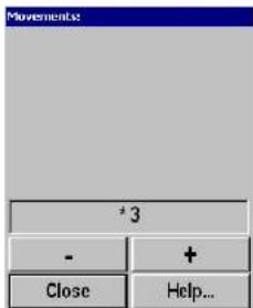
The Movementsfunction makes it possible to estimate the position of a tracked school at a given time (from one to ten minutes). Estimate school position is presented by a violet dot. When selecting 0, the movement estimation is switched Off.
Noise Level
The Noise Level button is located in the Horizontal menu.
Noise Level 0.0
The Noise level button provides a readout of the current noise in the waters surrounding the vessel. It is only used for test purposes. This noise is caused by water flow, mechanical disturbances from hull and engine, and even from other electric or electronic systems on the vessel. In order to obtain the best possible sonar result, the noise level readout must be as low as possible, and you should read a value close to 47 dB.
Palette
The Palette button is located in the Display menu.
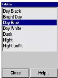
The Paletteparameter dialogue is used to select background colours and day/night brightness of the display.
Parameters
Panel Backlight
The Panel Backlight button is located in the Display menu.
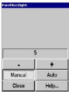
ThePanelBacklightcontrols the illumination on the keyboard on the Sonar Operating Panel in 8 steps (0 - 7). Note that the Panel Backlight can only be manually operated. The Autobutton is added for future expansion.
PP Filter
The PP Filter can be accessed from the Horizontal and Verticalmenus.

The PPFilter(Ping-to-Ping filter) reduces unwanted noise and echoes from the screen. The filter has three different strengths. As theping-to-pingfiltercomparestheechoesfromthelast 2 (Weak), 4 (Medium) or 8 (Strong) pings, it will take this selected amounts of pings to make a stable presentation when changing most of the sonarfunctions. The filteringroutinetakeshevessel' smovements into consideration when comparing the echoes from ping to ping.
Parameters
Pulse Form
The Pulse Form is accessed from the Horizontal and Vertical menus.

The Pulse Form parameter dialogue is used to select the form of the transmitter pulse. This could either be CW (Continuous Wave) with different pulse lengths, or FM (Frequency Modulation) with different pulse lengths and number of frequencies.
| Range (meters) | CW Puiselength(ms) | AUTO mode(ms) | FM Puiselength(ms) | ||
| ShortNormalLong | ShortNormalLong | ||||
CW (Continuous Wave)
The frequency of the transmitter pulse is here constant, equal to the selected frequency (if the optional multiple frequencies are installed).
There is a selection between three different pulse lengths:
Short, Normal and Long. In addition the pulse length will change automatically in accordance with the selected range. The table shows the different pulse lengths given in milliseconds (ms).
Auto
In Auto mode, the transmitter pulse is made with a combination of FM and CW to give an optimal echo presentation for all ranges. This combination is designed from operational experience, and will change automatically between FM Long in the shorter ranges, and CW Long in the longer ranges. The table shows the mode and pulse lengths (ms) which are used for the different ranges.
FM (Frequency Modulation)
In the FM mode, the transmitter pulse is frequency modulated. This provides a stable echo presentation and greater ability of detection as noise and reverberation are reduced.
There is a selection between these different FM modes:
- FM Short - Transmits one-frequency pulse with a total pulse length of 3.2 ms for all ranges
Range
The Range parameter can be accessed from the button in the Horizontal and Vertical menus.

Horizontal and vertical range is normally selected using the SH80 Sonar Operating Panel. You can also control these settings directly on the Rangebutton. The available choices are listed in this dialogue.
The Range buttons are described in the Sonar OperatingPanelchapter.
Available ranges (in meters) are:
50, 75, 100, 150, 200, 300, 400, 500, 600, 750, 1000, 1200, 1500 and 2000.
In addition to the readout on the menu, the current horizontal range is normally displayed over the tilt indicator in the upper, left-hand corner of the display.
The following options are available in the Range parameter dialogue:
Manual - Allows you to change the range manually.
Auto - Enables automatic range selection during position- and target tracking. This allows for optimal tracking.
To maintain a steady display during seine setting, the lower automatic range is set to 450 meters. Changing the range or pressing the Manual buttons will stop the automatic ranging
Range (Catch View)
The Range (Catch View) button is located in the Catch View menu.
The CatchView menu is activated by pressing the View button on The Sonar Operating Panel (or the middle mouse button), while the cursor is located in the Catch view, and then selecting View menu on the View pop-up menu.

The Range in the CatchView may be selected manually or automatically.
In Manual, the range scale can be selected from the list in the dialogue.
In Auto, the CatchView range will automatically follow the range
RCG (Reverberation Controlled Gain)
The RCG button is located in the Horizontal and Vertical menus.

The RCG (Reverberation Controlled Gain) regulates the receiver gain individually for each of the 64 receiving beams.
In Weak and Medium selections, signals with small variations, like propeller noise, surface and bottom reverberations will be removed, while signals with fast variations, like target echoes or bottom echoes, will not be removed. In Strong, a special filter removes the bottom, while echoes on the bottom will be represented.
Note that scattered fish can be perceived as reverberation. The
Recall
The Recall button is located in the Store/Recall menu, which is accessed from the Setup menu.
The Recall button is used to retrieve the previously stored display information. You can select which storage image you wish to see byselectingitfromthelistoftemporary or permanent files, orstart a playback sequence. When a playbeck sequence is finished, the last picture of the sequence will remain "frozen" on the display.
The recalled image is clearly identified with the word "Recall".
To exit the recall mode, press the Object button on the Sonar Operating Panel or the right mouse button.
Recall Mode
The Recall Mode button is located in the Store/Recall menu, which is accessed from the Setup menu.

Ruler
To create a ruler, open the Object pop-up menu by clicking Object on the Sonar Operating Panel (or the right mouse button), and select New ruler in the Object pop-up menu.
To open the Ruler dialogue, click on the ruler with the Select button.

The Rulerdialogue provides information about the currently selected ruler, its length and angle. The same information is also provided next to the ruler on the display.
TheDeletebutton allowsyou to remove the ruler from thedisplay.
Related topics
Scale
The Scale button is located in the Geo View menu.
The GeoView menu is activated by pressing the View button on the Sonar Operating Panel or the middle mouse button in any horizontal view, and then selecting View menu in the View pop-up menu.

TheScaleof the horizontal presentations maybe selected between 25% and 200%, where 100% is the default scale.
Parameters
School
The School button is located in the Setup menu.
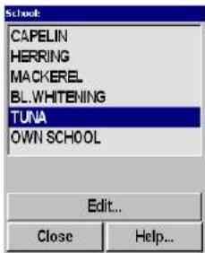
The School parameter is used to obtain information of the volume estimation of a school in the automatic target tracking program. Four types of known fish species plusOwnschool can be selected. Assumed density can be adjusted according to experience by use of the EditSchoolbutton.
Related topics
→ EditSchool;page101
Scientific Output (Option)
The Scientific Output button is located in the Setup menu.
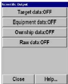
The Scientific Output functionality is designed to be used when the sonar is used for scientific purposes. When enabled, the sonar will provide special information on an ethernet port.
The data provided by the the Scientific Output function can be enabled or disabled using the following buttons:
- Target Data - consists of all the actual target track data for all targets which are in automatically target track mode.
- Equipment Data - consists of all gear parameter data for the selected gear, both data which are manually selected, and data which are automatically transferred from the ITI trawl
Search Sector
The Search Sector is accessed from the Bearing paramater dialogue, which is turn is opened from the Horizontal menu.
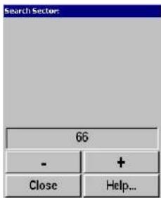
The Search Sector parameter dialogue is used to define the size (in degrees) of the search sector, in which the audio beam will travel back and forth when the Auto Search mode is enabled.
Related topics
→ Bearing,page88
→ AutoSearch,page32
Search Step
The Search Step is accessed from the Bearing parameter dialoge, which is turn is opened from the Horizontal menu.
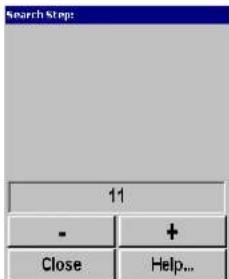
The Search Step parameter dialogue is used to define the size of each step (in degrees) the audio beam will travel between each transmission. This function is used when the Auto Search mode is enabled.
Related topics
→ Bearing,page88
→ AutoSearch,page32
Slant Range/ True Range
The Slant Range/True Range button is located in the Cosmeticsmenu, which inturnis accessed from the Display menu.
True Range
In the True Range presentation the echo distance is the distance which the vessel must sail in order to come on top of the target.
Slant Range
In the SlantRangepresentation the distance to the target is measured along the tilt angle.

Speed
The Speed parameter is accessed by pressing the Spd (Speed) button in the Status dialogue at the bottom of the menus.

The Speedreadout is a repetition of the connected speed input source, which can be a separate speed log input or data from the connected (D)GPS. In case of a fault in the speed data, the speed can be set manually by pressing Manual and using the + and - buttons to alter the speed value.
Parameters
Stabilizer
The Stabilizer button is located in the Setup menu.
Stabilizer: OFF
Stabilizer: ON
Whenthestabilizer isactive, the transducerbeam will bestabilized electronically for roll and pitch. The beam direction will change continuously according to the vessel's movements, and thus be compensated whenever the vessel is out of trim. The beam angle will always be maintained as if referred to a "flat" water surface. When the stabilizer is used, this will also allow you to use the PP Filterin rough seas. This filter will give a cleaner and more stable echo presentation.
The first example in the figure (top vessel A) indicates the sonar beam without stabilization, while the bottom vessel (B) indicates the stable sonar beam with the stabilization in operation.

natural_image
Line drawing of three ships on a river with ropes, no text or symbols presentStatus
The Statusdialogue is the default view displayed in the lower, right hand corner of the screen.
The Status dialogue can not be closed, but if an other parameter is selected it will be overwritten. The dialogue contains a transducer position indicator, as well as readouts of current time, date, latitude, longitude, heading and speed.

Related topics
→ Transducer.page141
→ TimeandDate,page138
→ Heading,page107
Store
The Store button is located in the Store/Recall menu, which is accessed from the Setup menu.
The Store button is used to store display information. This may be a sequence loop or single display pictures, as selected in the Store modedialogue.
If a sequence loop storage is selected, the Store button is used for start and stop of the storage. If single picture storage is selected, a new picture storage is made each time the Store button is pressed.
Store Mode
The Store Mode button is located in the Store/Recall menu, which is accessed from the Setup menu.

Target Track
The Target Track button is located in the GeoView menu.
The GeoView menu is activated by pressing the View button on the Sonar Operating Panel or the middle mouse button in any horizontal view, and then selecting View menu in the View pop-up menu.
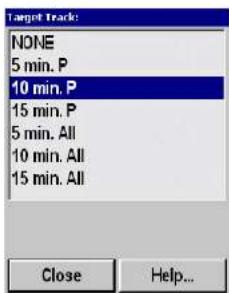
TargetTracklinessshowsthemovement history of targetsasaline after the respective symbols. They are shown as straight line segments drawn between each position fix, with optional minute markers to be added for each minute along the line.
Tilt
The Tilt parameters are accessed from the Horizontal menu.
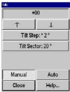
The Tilt is normally controlled from the Sonar Operating Panel. The transducer can be tilted electronically from +10 degrees up to -60 degrees down. In addition to the readout on the Tiltbutton, the tilt angle is normally repeated on the tilt indicator in the upper left corner of the display, and in the vertical modes; directly in the vertical slice.
Arrows
Manual tilt up/down.
Tilt Step
This button opens a new dialogue to select the tilt steps in the Auto tilt mode. It can be set from 1 to 10 degrees directly with the increase/decrease function on the Tilt Step button, or by the - and + buttons in the Tiltstepparameter dialogue.
Tilt Sector
This button opens a new dialogue to select the active tilt sector in the Auto tilt mode. It can be set from 2 to 70 degrees directly with the increase/decrease function on the Tilt Sector button, or by the - and + buttons in the Tilt Sector dialogue.
Manual
Time and Date
The Time and Date dialogue box is accessed by pressing the Time or Date buttons in the default Status dialogue at the bottom of the menu. Time and date are battery powered and stored in the memory when the sonar is switched off.

The Date/Time properties dialoguebox is provided by the sonar's operating system, and it is used to change time, date and time zone settings.
Track History
The Track History is accessed from the Cosmetics menu.
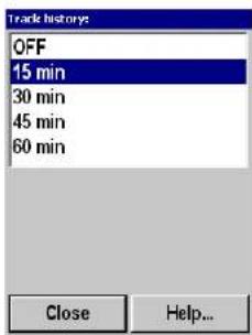
The Track History lines show the movement history of your own ship as a line after the vessel symbol. When this function is active, the length (in time) of the history lines can be set.
It is possible to place minute markers on the history line. To activate this, press the Minute Marker button ("on/off switch") on the Cosmetics menu. These markers are shown as small circles on the history line.
Track Window
The Track Window parameter is accessed from the Setup menu.

The TrackWindowcommand enables you to adjust the track windowsize. Alargertrackwindowwillenable thesystem to track a large target more easily, but the system will be more susceptible to background noise. Smaller targets may be ignored if there is a lot of noise in the area, as the system will track the strongest echo within the track window.
Parameters
Transducer
The Transducer button is located in the Status dialogue at the bottom of the menus.

The Transducer position is normally selected from the Sonar Operating Panel, and in addition to the LED indicators on the panel, the transducer position will be indicated in the Status dialogue.
The Off, Up, Middle and Down controls in the Transducer dialogue correspond to their respective buttons on the Sonar Operating Panelandmakesitpossibletomaketheselectionsbythe trackball.
The Middle position button allows you to define the vertical location of the middle position.
TVG (Time Variable Gain)
The TVG button is located in the Horizontal and Vertical menus.

The TVG controls the gain in the signal amplifier. The gain is weakest just after the ping, and increases in accordance with time (and therefore range).
In addition to Off and Auto, the TVG can be selected with six different curve slopes, each having different gain regulations. The Autoline in the menu is marked with an asterisk to indicate the theoretically correct setting for the different range settings.
With this setting, the gain is adjusted in such way that a school of fish with a certain size and density will be presented with
Parameters
Tx Power
The Tx Power button is accessed from the Horizontal and Verticalmenus.
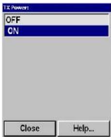
The TXPowerisusedtoswitchtransmitteroutputpoweronoroff. Note that the TX Power parameter is common for all the menus. Thus, if the Tx Powerischanged in one menu, it will automatically also be changed in all other menus.
Units
The Units button is located on the Display menu. When activated, it opens the Engineering Units parameter dialogue.

This parameter dialogue is used to set up the various units used by the sonar to display all measurements. Separate units are available for Range, Equipment, Depth, Speed, Position and Temperature. When any of these buttons are pressed, dedicated parameter dialogues are provided to make the selection.
The following units are available:
Range: Meters, Nautical mile, Feet, Yards
Equipment: Meter, Fathoms, Feet
Depth: Meter, Eathome, East
User Setting
User Setting is accessed from the Setup menu.

The User Setting is used to store the parameter settings for different type of fisheries, or individual user related settings. The storedsettingscaneasilybeloaded backinto the operative menus using the Modebuttons on theSonar Operating Panel.
Load Selected Setting
Use this option to retrieve the previously stored setting. Click on the chosen setting in the dialogue to highlight it, and then click this button to retrieve it.
Save Current Settings
Use this option to save all the currently used parameter settings. You will always save your current setting as a "new user". By default the setting will be named User N, and "N" is simply the next available number.
Delete
Click to select one of the settings in the dialogue, then click this button to delete it.
Rename
This option provides an on-screen keyboard to rename the
Wind Direction
The Wind Direction button is located in the Setup menu.

The wind marker is show in the outer area of the echo presentation as a white arrow. This arrow can be manually adjusted for indication of the wind or current direction, or automatically show the wind direction if a wind sensor is connected.
Parameters
Wind Speed
The Wind Speed button is located in the Setup menu.
Wind Speed: 0 m/s
The Wind Speed is not used as a parameter in the sonar. It is only a readout if a wind sensor is connected.
Zoom
The Zoom button is located in the Vertical View menu.

The Zoomfunction is used to zoom in on the vertical view around the trawl symbol or the bottom. To zoom in on the bottom, an external echo sounder must be connected to the sonar.
Parameters
Zoom Scale
The Zoom button is located in the Vertical View menu.

bar
| Zoom Scale | Percentage (%) | | :--- | :--- | | 10 | 25 | | 50 | 70 | | Close | Help... |The Zoom Scale is used for scaling the zoom around the bottom.
ON-BOARD MAINTENANCE
Introduction
This section deals with maintenance work that may be carried out by the user. In addition to cleaning the cabinets and dust filters, you should inspect the sonar room at least once a week. The ventilation and heating system, as well as the bilge pump arrangement should then be checked to be in good working order.
For location and replacing of fuses, refer to the chapter for the unit in question.
Major repairs and complete overhaul of the sonar must be left to an authorized Simrad service engineer.
Topics
→ Preventivemaintenanceschedule,page151
→ Wheelhouseunits,page152
→ Transceiverunit, page154
→ Hullunit, page 156
Preventive maintenance schedule
Observe the following schedule for preventive maintenance on the SH80 sonar system. Use this information to create a preventive maintenance log, and make sure that every maintenance action is logged accurately.
Note: Its very important that the preventivemaintenance is carried out correctly as at the specified intervals. All guarantees is voided unless this schedule is followed.
Every three months
- Inspect the dust filters on the Sonar Processor Unit. Clean the filters, or replace if required.
- Inspect the dust filters on the Transceiver Unit. Clean the filters, or replace if required.
- Carry out all the necessary lubrication of the hull unit.
Every time the ship is in dock
- Perform a close visual inspection of the sonar trunk and the transducer.
- If required, clean the trunk and the transducer surface for marine growth.
Wheelhouse units
Cleaning
The units must be kept clean and dry. Remove salt water residue with a soft cloth moistened in fresh water. Do not use strong solvents.
Note: Thedisplayscreenmustbehandledwithcaretoavoiddamage totheanti-glarefiltercoating.Useasoftclothwithoutany strongsolventswhencleaningit.
Dust filter
To avoid overheating, the dust filter(s) must be inspected, and if necessary, cleaned once every third month.
Due to design changes, your sonar may be equipped with either of the following computers.
APC10 Sonar Processor Unit
The dust filter on the APC10 is located on the air inlet on the rear side of the Sonar Processor Unit.

MC70 Sonar Processor Unit
The two dust filters on the MC70 are located on the air inlets on the front side of the Sonar Processor Unit.
The dust filters on the MC70 Sonar Processor Unit
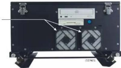
The filter is accessible by simply pulling off the filter grid. Each filter should be vacuum cleaned, or washed in soap and water. If washed, the filter must be dried thoroughly before being reinstalled.
Transceiver Unit
Dust filter
There is a dust filter in the bottom of the Transceiver Unit. To avoid overheating, this must be inspected, and if necessary, cleaned once every third month.
The dust filter is accessible from the outside of the Transceiver Unit, by unscrewing the eight finger nuts in the bottom of the unit. The filter should be vacuum cleaned, or washed in soap and water. If washed, the filter must be dried thoroughly before being reinstalled.
Replacing fuses
The Transceiver Unit is fused with two 8A slow blow main fuses (F205 and F206) located on the front of the Power Control Unit.
SH80TransceiverUnit fuselocations.
(A)=Dustfilter

If one of the fuses are blown, the lamp L203 should be lit, while lamp L204 should be extinguished. If lamp L203 is not lit, check the fuses on the ship's main power system.
TheSH80TransceiverUnit powersupplysystem

Hull unit
General
The sonar hull unit must be under continuous watch as a part of the vessel's machinery. As the hull unit may be exposed to severe strain because of pitching and vibrations, it must be inspected regularly for loose parts.
In addition to lubrication, check for signs of corrosion. If required, clean the corroded areas and paint over with a high quality protective paint.
Topics
→ Hullunitfamiliarization,page157
→ Precautionswhendockingthevessel,page158
→ Cleaningthetransducer,page160
→ Hoistmotoroverloadprotection, page 161
→ Emergencyhoistingandlowering,page162
→ Lubrication,page163
Hull unit familiarization
Observe the illustration below for the identification of the main parts.

A) Upper limits switch S304
B)Transducercable
C)Transducershaft
D) LowerlimitswitchS305
E) Pressurereleaseplug(on rearside)
F) Airbleedingplug
G)Hoistmotor
H)MotorControlUnit
I)Gantry
J) Mountingflange
K) Installationtrunk
L)Transducer
Docking the vessel
When docking the vessel, great care must be taken not to damage the sonar trunk and protecting blister.
Warning: Thesonarmustneverbepoweredupwhenthe
shipisindrydock. Thetransducerwillbe
damagedifittransmitsinopenair.Toprevent
inadvertentuseofthesonar, disconnectthe
mainsplugontheSonarProcessorUnitwhenever
thevesselisindrydock.
The location of S302 in the Motor Control Unit

On vessels which have been in dock, the Hull Unit must be thoroughly examined, and the hoist/lower functions must be checked out and observed while operating the Hoist/Lower Switch (S302 in the Motor Control Unit). The hoist/lower motor will automatically stop when the transducer shaft reaches the upper or lower limit switch.
Remember to set the hoisting/ lowering switch back to Remote for normal operation.
Cleaning the transducer
The transducer normally needs little attention. However, the transducer face should be inspected and cleaned whenever the vessel is in dock.
To lower the transducer when in dock, use the hoist/lower switch S302 in the Motor Control Unit (mounted on the gantry). Set the switch to STOP to position the transducer at any vertical location.
Do not use strong solvents, but a normal synthetic soap and water. Marine growth must be carefully removed with fine-grade sandpaper or emery paper.
Note: Thetransducersurfacemustnotbepainted.
Hoist motor overload protection
To prevent the hoist/lower motor from overload, an overload circuit breaker S301 is located in the Motor Control Unit. This may automatically be switched off during hoisting if the vessel's speed is too high, or if the transducer shaft has been bent.
To reset the motor overload switch, open the Motor Control Unit, locate the switch S301 and press the button marked 1.
ThelocationofS301in theMotorControlUnit

Emergency hoisting and lowering
In case of a failure or an emergency in the normal hoist/lower operation controlled from the Sonar Operating Panel, the transducer may be hoisted and lowered from the Sonar Room.
Local control switch S302
If the 3-phase voltage for the hoist/lower motor and the +24 Vdc stand-by voltage from the Transceiver Unit are available, the transducer can be hoisted or lowered by means of switch S302 in the Motor Control Unit. The motor will automatically stop when the transducer shaft reaches the upper or lower limit switch.
Remember to set the switch back to Remote position when finished.
Hoist/ lower contactors K301 and K302
If the 3-phase voltage for the hoist/lower motor is available, the transducer can be hoisted and lowered by operating the hoist (K301) and lower (K302) contactors in the Motor Control Unit by activating the small switch handle on the front of the contactor.
Warning: Theswitchesmustbereleasedbeforethe transducershaftreachesupperorlowerposition, asthisoperationoverridesthetwolimitswitches.
Lubrication of the Hull Unit
From the factory, the Hull Unit is lubricated with the types of oil or grease as specified below. However, if of equal quality, other types may be used. The following number refer to the lubrication points on the illustration to the left.

(1) The ball bearing on the top of the hoist/lower screw must be lubricated with normal ball bearing grease.
(2) The hoisting spindle should be lubricated with TonnaSlidewayOilsS68.
(3) Topping up the shaft sleeve through the grease nipple is only required if the shaft is dry of lubrication, or if water tends to force its way up along the shaft. The shaft sleeve is filled with Esso CazarK1.
Warning: Whenyoutopuptheshaft sleeve with oil, you must open the pressurereleaseplugtoavoiddamage totheshaftbearings.
(A)=Pressurereleaseplug
(B)=Airbleedingcock
©2005 Simrad AS
ISBN 82-8066-007-0
- Highfrequencyfisherysonar
- About this document
- Sections
- System description
- Display modes
- Sonar Operating Panel
- Operation
- Menu description
- Parameters
- SYSTEM DESCRIPTION 1......
- DISPLAY MODES 13....
- Operator manual
- OPERATION 36....
- Simrad SH80
- ON-BOARD MAINTENANCE 150....
- SYSTEM DESCRIPTION
- Introduction
- System overview
- Main units
- Wheelhouse units
- Sonar room units
- System diagram
- Options
- General
- Multiple-frequency
- Scientific output
- Functional description
- Functional principles
- Stabilization system
- Reception
- RCG(ReverberationControlledGain)
- PPFilter
- Relatedtopics
- Peripheral equipment
- DISPLAY MODES
- Topics
- Bow Up
- North Up
- True Motion
- 180°/Audio
- 270°/ Vertical
- Bow Up / Vertical
- True Motion/ Vertical
- Dual 1
- Dual 2
- SONAR OPERATING PANEL
- Main switch
- Power
- Up
- Middle
- Symbol
- Target marker
- Own ship marker
- Seine circle
- Trawl symbol
- Mode
- Related topics
- Gain
- Horizontal gain
- Vertical gain
- Range
- Horizontal range
- Vertical range
- Cursor
- Menu
- Select
- Trackball
- Train
- Manual
- Auto search
- Target track
- Tilt
- Manual tilt
- Auto tilt
- Various
- Mute
- Record
- Zoom
- Off centre
- OPERATION
- Maintaining the sonar
- Maintenance procedures
- Important when docking the vessel
- Start and stop procedures
- Start procedure
- Disconnected mains
- Design change
- Stop procedure
- Dry-docking safety measures
- Menu operation
- Screen presentations
- Menu presentation
- Menu structure
- Menu buttons
- Selecting a new parameter value
- Second method:
- Stored parameters
- Default settings
- User settings
- Parameter memory
- Visual aids
- Common information on the display
- Cosmetics
- Installation of options
- Procedure:
- On-line help
- MENU DESCRIPTIONS
- Active menus
- Overview
- Horizontal
- Parameters
- Vertical
- Display
- Setup
- Objects
- Temporary menus
- Store/ Recall
- System test
- Sort Modes
- Pop-up menus
- View pop-up
- Object pop-up
- View menus
- GeoView
- VerticalView
- CatchView
- Messages
- Message categories
- Warnings
- Operator alarms
- Operator Alarm parameters
- System alarms
- Errors
- About parameter dialogues and help
- Alphabetical list
- About
- Beam
- Bearing (Horizontal)
- Left/ Right arrow
- Absolute/ Relative
- Manual/Auto
- Bearing (Display)
- Bearing: True North
- Bearing: Relative Ship
- Bearing (Vertical)
- Colour Threshold
- Colours
- Data Source
- Dead Reckoning
- Dead Reckoning: OFF
- Dead Reckoning: ON
- Default Setting
- Direction Indicator
- Edit Gear (Purse)
- Depth
- Edit Gear (Trawl)
- Distance
- Width
- Length
- Edit School
- External Synchronization
- Sync mode
- Fish Alarm
- Start range
- End range
- Frequency
- Gear
- Heading
- Inspect Object
- Language
- Message Bar
- Mode Buttons
- Mode Buttons: MODE
- Mode Buttons: USER
- Movements
- Noise Level
- Noise Level 0.0
- Palette
- Panel Backlight
- PP Filter
- Pulse Form
- CW (Continuous Wave)
- Auto
- FM (Frequency Modulation)
- Range (Catch View)
- RCG (Reverberation Controlled Gain)
- Recall
- Recall Mode
- Ruler
- Scale
- School
- Scientific Output (Option)
- Search Sector
- Search Step
- Slant Range/ True Range
- True Range
- Slant Range
- Speed
- Stabilizer
- Status
- Store
- Store Mode
- Arrows
- Tilt Step
- Tilt Sector
- Time and Date
- Track History
- Track Window
- Transducer
- TVG (Time Variable Gain)
- Tx Power
- Units
- User Setting
- Load Selected Setting
- Save Current Settings
- Delete
- Rename
- Wind Direction
- Wind Speed
- Zoom Scale
- ON-BOARD MAINTENANCE
- Preventive maintenance schedule
- Every three months
- Every time the ship is in dock
- Cleaning
- Dust filter
- APC10 Sonar Processor Unit
- MC70 Sonar Processor Unit
- Transceiver Unit
- Replacing fuses
- Hull unit
- Hull unit familiarization
- Docking the vessel
- Cleaning the transducer
- Hoist motor overload protection
- Emergency hoisting and lowering
- Local control switch S302
- Hoist/ lower contactors K301 and K302
- Lubrication of the Hull Unit
Brand : SIMRAD
Model : SH80
Category : Marine Radar