EVO-CF30MW - Household Fan Evolar - Free user manual and instructions
Find the device manual for free EVO-CF30MW Evolar in PDF.


| Product Type | Domestic Fan |
| Model | EVO-CF30MW |
| Brand | Evolar |
| Dimensions (H x W x D) | Approx. 120 x 40 x 40 cm |
| Weight | Approx. 5 kg |
| Power Supply | 220-240 V ~ 50 Hz |
| Power Consumption | 30 W |
| Fan Speed Settings | 3 speeds (low, medium, high) |
| Oscillation | Yes, 90° wide-angle |
| Tilt Adjustment | Yes, manual tilt up/down |
| Remote Control | Included (battery not included) |
| Timer | Up to 7 hours |
| Blade Diameter | 30 cm |
| Noise Level | ≤ 55 dB |
| Material | ABS plastic, metal stand |
| Safety Features | Overheat protection, tip-over switch |
| Cleaning | Unplug before cleaning; wipe with damp cloth; do not immerse |
| Storage | Keep in dry place; disassemble if needed |
| Spare Parts Availability | Contact Evolar service for replacements |
| Manual Languages | English (available in other languages on request) |
Frequently Asked Questions - EVO-CF30MW Evolar
User questions about EVO-CF30MW Evolar
0 question about this device. Answer the ones you know or ask your own.
Ask a new question about this device
Download the instructions for your Household Fan in PDF format for free! Find your manual EVO-CF30MW - Evolar and take your electronic device back in hand. On this page are published all the documents necessary for the use of your device. EVO-CF30MW by Evolar.
USER MANUAL EVO-CF30MW Evolar
natural_image
Line drawing of a five-blade propeller with a central hub and fan (no text or symbols)- Plafondhouder

natural_image
Exploded view diagram of a ceiling lamp with exposed internal components and wiring (no text or symbols)- Motor / Ventilator-element
- Lampenkap
Afstandsbediening

natural_image
Line drawings of four electronic devices: a remote control unit, a remote control with buttons, a battery pack, and a water dispenser (no text or symbols)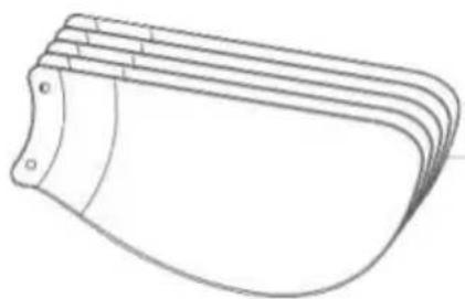
natural_image
Line drawing of a curved mechanical component with multiple grooves (no text or symbols)natural_image
Diagram showing various types of mechanical fasteners and bolts arranged in rows, with no visible text or labels.
natural_image
Three simple geometric shapes: two overlapping squares and one with a folded paperclip (no text or symbols)
natural_image
Simple line drawing of an open book with a lowercase 'i' symbol on the right page (no text or labels)Plafondventilator installeren
Stap 1 - Plafondhouder en ventilatorelement installeren

Ventilator trilt of wiebelt
natural_image
Line drawing of a curved object with a labeled component (1), no text or symbols present
evolar

natural_image
Line drawing of a five-blade propeller with a conical top and three blades (no text or symbols)EVO-F30MW/B
Ceiling fan Installation instructions
SAFETY TIPS
WARNING: To reduce the risk of electrical shock, turn off the electricity to the fan at the main fuse box or circuit panel before you begin the fan installation or before servicing the fan or installing accessories.
READ ALL INSTRUCTIONS AND SAFETY INFORMATION CAREFULLY BEFORE INSTALLING YOUR FAN AND SAVE THESE INSTRUCTIONS.
CAUTION: To avoid personal injury, the use of gloves may be necessary while handling fan parts with sharp edges.
-
Make sure all electrical connections comply with Local Codes or Ordinances, the National Electrical Code. If you are unfamiliar with electrical wiring or if the house/building wires are different colors than those referred to in the instruction please use a qualified electrician.
-
Make sure you have a location selected for your fan that allows clear space for the blades to rotate and at least seven (7) feet (2.3 meters) of clearance between the floor and the fan blade tips. The fan should be mounted so that the tips of the blades are at least thirty (30) inches (76 centimeters) from walls or other upright structures.
-
The outlet box and ceiling support joist used must be securely mounted, and capable of supporting at least 100 Pounds (45.4 kilograms). The outlet box must be supported directly by the building structure. Make sure the electrical box that will hold the ceiling fan is fan-rated. There should be an inscription on the box indicating it.
WARNING: To reduce the risk of fire, electrical shock, or personal injury, mount to the outlet box marked “Acceptable for Fan Support,” and use the mounting screws provided with the outlet box. Most outlet boxes commonly used for the support of lighting fixtures are not acceptable for fan support and may need to be replaced. Consult a qualified electrician if in doubt.
- After making electrical connections, spliced conductors should be turned upward and pushed carefully up into the outlet box. The wires should be spread apart with the grounded conductor and the equipment-grounding conductor on opposite sides of the outlet box.
WARNING: To reduce the risk of electrical shock, fire and to prevent humming noise do not use this fan with any solid state speed control device or control fan speed with a full range dimmer switch. Using a full range dimmer switch to control fan speed will cause a loud humming noise from fan.
- Do not operate the reverse switch until fan has come to a complete stop.(If included Forward/Reverse Switch)
7.Do not insert anything between the fan blades while they are rotating.
WARNING: To reduce the risk of personal Injury, do not bend the blade brackets when installing the brackets, balancing the blades, or cleaning the fan. Do not insert foreign objects in between rotating fan blades.
WARNING: To avoid personal injury or damage to the fan and other items, be cautious when working around or cleaning the fan.
- Do not use water or detergents when cleaning the fan or fan blades. A dry dust cloth or lightly dampened cloth will be suitable for most cleaning.
WARNING: To reduce the risk of personal injury, use only parts provided with this fan. The use of parts OTHER than those provided with this fan will void the warranty.
NOTE: The important safety precautions and instructions appearing in the manual are not meant to Cover all possible conditions and situations that may occur. It must be understood that common sense and caution are necessary factors in the installation and operation of this fan.
Preparing for installation

Package Lists

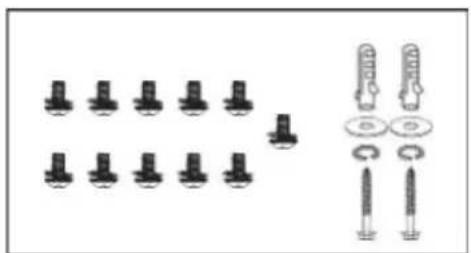
natural_image
Diagram showing various types of mechanical fasteners and bolts arranged in rows, with no visible text or labels.
natural_image
Three simple geometric shapes: two squares and one U-shaped paperclip, drawn with thin lines on a white background (no text or symbols)
natural_image
Simple line drawing of an open book with a lowercase 'i' symbol on the right page (no text or labels)Installing the ceiling fan
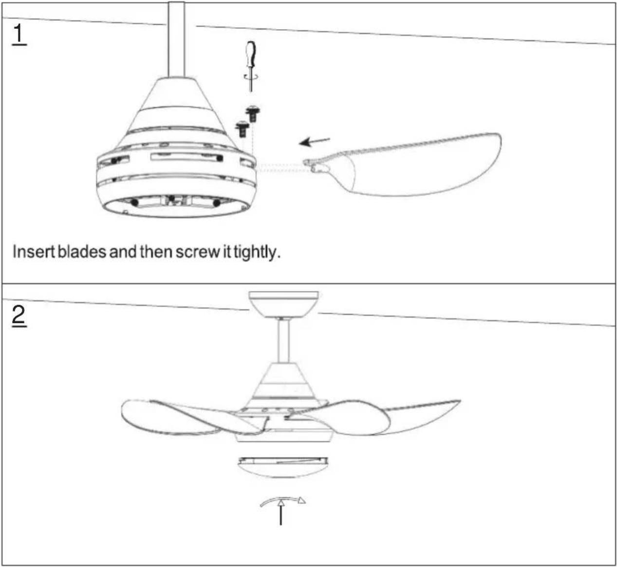
Step 1 (Ceiling bracket and fan body installation)
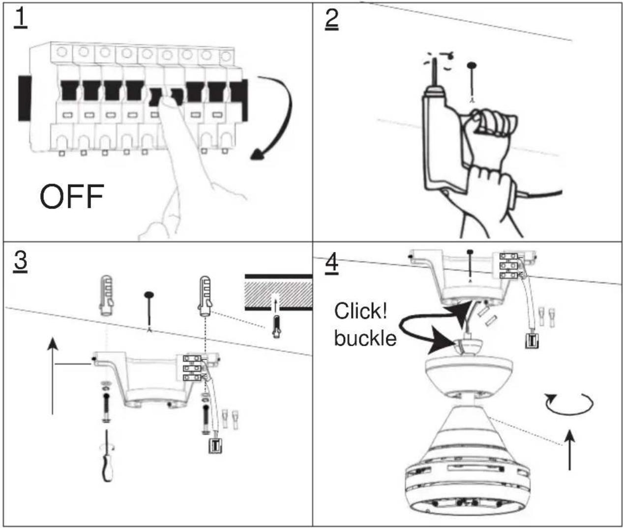
Step 2 (Put receiver into ceiling bracket and wiring)
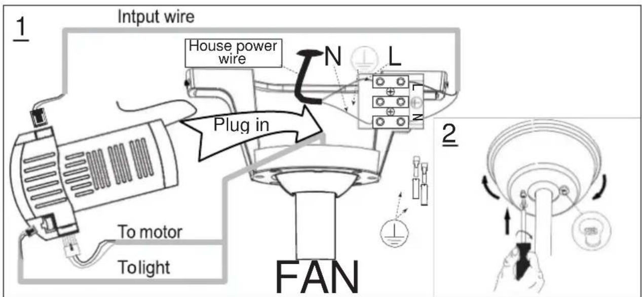
Step 3 ( Blades and Light Shade installation)
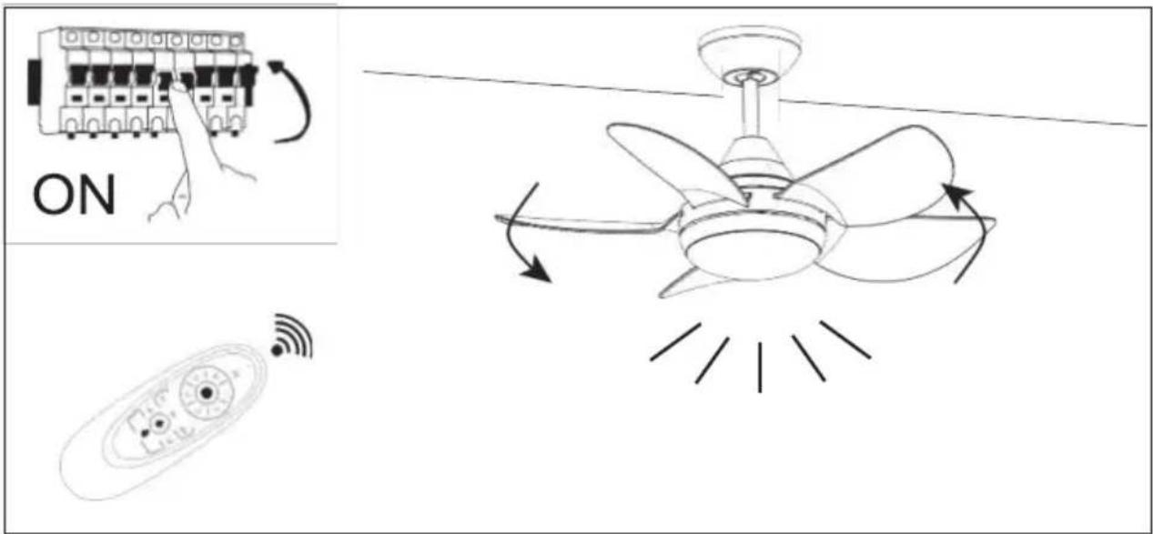
Step 4(Switch on and ceiling fan works)
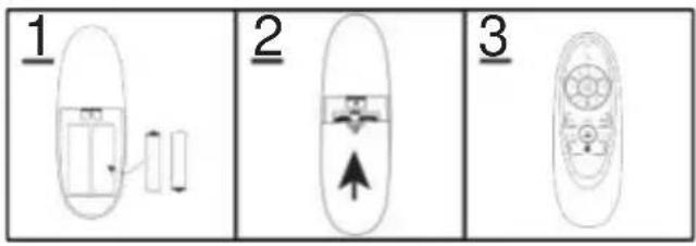
Remote control (emitter) operation

If emitter can not control the far
- Please check whether the battery is installed correctly and whether it is charged. If necessary, replace the remote control battery.
- Please check if there are similar remote control products working nearby, because remote control products of the same frequency will interfere with each other.
- Use learning code matching mode is used between emitter and receiver Turn "ON" the supply power within 30 seconds and press the emitter, 's " 🔊" button for 5 seconds. it can load normally after hearing a long sound"bee", which means learning successfully and it can works normally.
TroubleShooting
Fan does not work
- Check all fuses or circuit breakers if disconnecting the power supply to the fan.
- Turn off electrical power and check all wire connections to fan and in switch housing. It must be carried out by a electrician
Fan is noisy
- Assure that the screws fastening blade arm to motor are tight and the lock washers provided for that purpose have been used
- Lower the upper canopy to ensure a separation from the ceiling of no less than 3mm to reduce noisy
- Check to see if any of the blades are cracked. If so, replace all of the blades
- If this is the first use, leave the fan on for at least 8 hours. In the event that mechanical noise continues after this period, contact certified electrician
Fan turns but airflow is inadequate
- The fan may be running in reverse, so air is going upward.
- The room may contain items that obstruct the air flow.
- The fan may be too small for size of the room.
Fan shakes or wobbles
- The fan blades are not parallel to the ceiling. See Fig.1 how to inspect
- Make sure mounting bracket is tightened at outlet box with no movement at all.
- Make sure all screws holding the blades to the blade arm and blade arm to motor are tight.
- Use the balance kit and instructions to balance the fan. Please see the last pages described.
Balancing – Wobbling problems during fan operation
If the fan body wobbles during its operation, this is not a sign of malfunctioning (even if it wobbles a few centimeters). To reduce wobbling, you can, while the fan is off:
- Check that all blades are properly fastened by tightening their screws.
- Check the distance between each blade and the ceiling. Measurements to the ceiling can be carried out as shown in the following diagram. If variations exist and you have already correctly tightened the screws, check that all blades have the same shape. If any of them have a shape that is visibly different, this may be causing an imbalance during fan operation.

natural_image
Silhouette of a mechanical device with a ruler and scale, labeled Fig.1 (no text or symbols on the diagram itself)If you have completed the previous steps and the wobbling has not resolved, you should apply dynamic balancing with the kit provided, as explained below:
- Turn the fan on to the highest speed so that the greatest amount of wobbling is produced.
- Turn off the fan. Select a blade and place a clip on it (see diagram) halfway between the fastening and the far edge of the blade.
- Turn on the fan and check whether the wobbling has improved or gotten worse. Turn it off once again and if the wobbling has not improved, place the clip on another blade. Repeat this process and determine on which blade it improves the wobbling.
- Leave the clip on the blade that produces the best results. Move the clip forward or backwards on this blade until finding the position that offers the best results.
- Afterwards, remove the clip and place one of the weights on the upper part of the center line of the blade at the position where the clip was located.

natural_image
Line drawing of a curved mechanical component with a labeled part (1), no text or symbols present

- Plafondventilator installeren
- Ventilator trilt of wiebelt
- evolar
- SAFETY TIPS
- Preparing for installation
- Installing the ceiling fan
- Remote control (emitter) operation
- If emitter can not control the far
- TroubleShooting
- Fan does not work
- Fan is noisy
- Fan turns but airflow is inadequate
- Fan shakes or wobbles
- Balancing – Wobbling problems during fan operation
Brand : Evolar
Model : EVO-CF30MW
Category : Household Fan