
DDS108 - Beer dispenser Perlick - Free user manual and instructions
Find the device manual for free DDS108 Perlick in PDF.


| Product Type | Beer Dispenser (Kegerator) |
| Model | DDS108 |
| Brand | Perlick |
| Dimensions (W x D x H) | 15" x 24" x 33" (38.1 x 61.0 x 83.8 cm) |
| Weight | Approximately 80 lbs (36.3 kg) |
| Power Supply | 115 V, 60 Hz |
| Cooling System | Forced air cooling |
| Keg Capacity | Accepts 1/4 or 1/6 barrel kegs |
| Number of Faucets | 1 |
| Temperature Range | 34°F - 40°F (1°C - 4°C) |
| Refrigerant | R134a |
| Material | Stainless steel interior and exterior |
| Installation | Under-counter or freestanding |
| Cleaning | Removable drip tray, clean with mild soap and water |
| Safety Features | Automatic defrost, leveling legs |
| Warranty | 1 year parts and labor |
Frequently Asked Questions - DDS108 Perlick
User questions about DDS108 Perlick
0 question about this device. Answer the ones you know or ask your own.
Ask a new question about this device
Download the instructions for your Beer dispenser in PDF format for free! Find your manual DDS108 - Perlick and take your electronic device back in hand. On this page are published all the documents necessary for the use of your device. DDS108 by Perlick.
USER MANUAL DDS108 Perlick
Commercial Back Bar Refrigeration
Self-Contained and Remote

natural_image
Exterior view of a modern stainless steel multi-level refrigerator with glass doors and side shelves filled with various beverages (no visible text or labels)BBS60
(glass door option shown)

natural_image
Exterior view of a modern stainless steel double-decker refrigerator with glass doors showing interior shelves (no visible text or symbols)BBR96
(glass door and solid stainless steel door options shown)
Product Series Covered in this Manual:
| Self-Contained |
| BBS |
| BBSN |
| PTS |
| DZS |
| SDBS |
| SDPS |
| BBSLP |
| DDC |
| DDS |
| Remote |
| BBR |
| BBRN |
| PTR |
| SDBR |
| SDPR |
| BBRLP |
Scan here to download a pdf copy of this manual.

Table of Contents
1.0 GENERAL INFORMATION ...... 1-1
1.1 Use of Service Manual 1-1
1.2 Model Families 1-1
2.0 SAFETY INFORMATION 2-1
2.1 Refrigerant HFC-134a 2-1
2.2 Potential Problems with HFC-134a 2-1
2.3 Service Manual Safety Labels 2-1
3.0 TROUBLESHOOTING GUIDE – REFRIGERATION SYSTEM.... 3-1
4.0 TROUBLESHOOTING GUIDE – ELECTRICAL SYSTEM 4-1
5.0 TROUBLESHOOTING GUIDE – DOORS, DRAWERS AND SHELVING .... 5-1
6.0 REFRIGERATION SYSTEM REPAIR INSTRUCTIONS 6-1
6.1 Air Infiltration 6-1
6.2 Slide Out the Refrigeration Deck 6-2
6.3 Plumbing for Remote Drain 6-2
6.4 System Operating Pressures 6-3
6.4.1 First Time Pull Down 6-3
6.4.2 Normal Cycling....6-3
6.4.3 Stabilization 6-3
6.4.4 Service Values 6-3
6.5 De-Ice Blocked Evaporator Coil – Self-Contained Models 6-4
6.6 Air Flow Obstructions 6-5
6.7 Clean Condenser Coil 6-5
6.8 Ambient Temperature 6-5
6.10 Compressors and Condensing Unit 6-6
6.12 Replace Condenser Fan Motor 6-7
6.13 Replace Evaporator Fan Motor – Self-Contained Models 6-7
6.14 Replace Compressor 6-8
6.15 Leak Detection 6-8
6.16 Recharge Procedure 6-8
6.17 Replace compressor starting device – Self-contained models 6-9
6.18 Troubleshooting Guide – Refrigeration System: Variable Speed Compressor..... 6-10
16.18.1 Compressor/Inverter Test Procedures.... 6-10
16.18.2 Compressor Diagnostic.... 6-10
16.18.3 Inverter Diagnostic.... 6-11
16.18.4 Variable Speed Compressor Change.... 6-11
16.18.5 Troubleshooting After Compressor Replacement.... 6-11
7.0 ELECTRICAL SYSTEM REPAIR INSTRUCTIONS.... 7-1
7.1 Electrical Specifications 7-1
7.2 Wiring Diagrams 7-2
7.3 Load Operation Modes 7-23
7.4 Electronic Controller 7-23
7.5 Factory Set Point 7-24
7.5.1 Dixell Controller: Reset Factory Parameter Settings 7-24
7.5.2 Eliwell Controller: Reset Factory Parameter Settings 7-24
7.5.3 Replacing Control Module 7-25
7.5.3.1 Removing Dixell Controller 7-25
7.5.3.2 Installing Eliwell Controller 7-27
7.5.4 Temperature Probe 7-28
7.6 LED Lighting 7-28
7.6.1 Replace LED Light Strip 7-28
7.7 Replace DC Driver/Inverter 7-29
8.0 SERVICE INSTRUCTIONS - DOORS, DRAWERS, AND SHELVING 8-1
8.1 Proper Door and Drawer Usage 8-1
8.2 Reverse Door Swing 8-1
8.3 Replace Door Hinge 8-4
8.4 Sliding Door Models 8-4
8.4.1 Removing/Installing Sliding Doors 8-4
8.4.2 Adjusting Door Spring Tension 8-5
8.4.3 Torpedo Spring Adjustment 8-5
8.5 Drawer & Shelf Slides 8-5
8.5.1 Shelving Adjustment 8-5
8.5.2 Drawer Divider Adjustment 8-6
8.5.3 Cleaning/Lubricating Drawer Extenders 8-6
8.6 Replace Door & Drawer Gasket 8-6
8.7 Replace Door Handle 8-7
8.8 Locks 8-7
8.9 Custom Overlay Panels.... 8-7
9.0 REPLACEMENT PARTS 9-1
9.1 Refrigeration Module (BBS, BBSN, PTS, SDBS, SDPS, DDS, DDC Model Series) .... 9-1
9.2 Refrigeration Module (BBSLP Model Series) 9-4
9.3 Refrigeration Module (DZS60 Model Series) 9-7
9.4 Refrigeration Module (DZS36 Model Series) 9-10
9.6 Fan Motor Assembly Parts (Self-Contained Model Series) 9-16
9.7 Low Profile Evaporator Parts (BBSLP Model Series) 9-17
9.8 Remote Evaporator Parts (BBR, BBRN, PTR, SDBR & BBRLP Model Series) 9-18
Table of Figures
Figure 1-1. Information Plate for Self-Contained Units 1-1
Figure 1-2. Information Plate for Remote Units 1-1
Figure 6-1. Sealing Compound at Wiring Pass-through 6-1
Figure 6-2. Floor Drain 6-1
Figure 6-3. Evaporator Condensate Trap 6-1
Figure 6-4. Remove Condensing Unit Bracket 6-2
Figure 6-5. Removing Refrigeration Deck 6-2
Figure 6-6. Remote Drain Tube 6-2
Figure 6-7. Service Valves 6-4
Figure 6-8. Removing Evaporator Fan Panel 6-4
Figure 6-9. Check for Obstructions.... 6-5
Figure 6-10. Fan Mounting Hardware 6-7
Figure 7-1. BBR24 Wiring Diagram 7-2
Figure 7-2. BBR48, BBR72, BBR96 Wiring Diagram 7-3
Figure 7-3. BBS36, BBS60, BBS84, BBS108 Wiring Diagram 7-4
Figure 7-4. BBSN32, BBSN52, BBSN72, BBSN92 Wiring Diagram 7-5
Figure 7-5. BBRN Wiring Diagram 7-6
Figure 7-6. BBRN60 and BBRN80 Wiring Diagram 7-7
Figure 7-7. PTS Wiring Diagram 7-8
Figure 7-8. PTR Wiring Diagram 7-9
Figure 7-11. Attach Probe to Bracket 7-27
Figure 7-12. Temperature Probe and Bracket 7-28
Figure 7-13. Interior LED Light 7-29
Figure 8-1. Door Removal 8-1
Figure 8-2. Hinge Removal 8-2
Figure 8-3. Hinge Installation 8-2
Figure 8-4. Door Brackets 8-2
Figure 8-5. Removing Front Panel 8-3
Figure 8-6. Bearing and V-Block 8-3
Figure 8-7. Door Hinges 8-3
Figure 8-8. Installing V-Block 8-4
Figure 8-9. Installing Door 8-4
Figure 8-10. Removing/Installing Sliding Door 8-4
Figure 8-11. Door Track 8-5
Figure 8-12. Shelf Locking Mechanism 8-5
Figure 8-13. Removing/Installing Drawer 8-6
Figure 8-14. Custom Panel 8-7
Table of Tables
Table 6-1. System Operating Pressures ...... 6-3
Table 6-2. Compressor Data.... 6-6
Table 7-1. Electrical Specifications ...... 7-1
Table 7-2. Load Operation Modes 7-23
Table 7-3. Controller Where-Used Table 7-23
Table 7-4. Factory Temperature Settings.... 7-24
Table 7-5. Temperature – Resistance Values 7-28
Table 8-1. Door Hinges 8-1
1.0 General Information
1.1 Use of Service Manual
This service manual is intended for use by a qualified service technician. It is provided as a guide to diagnose and repair service issues for the product models listed on the cover.
If you have any questions or require additional assistance, contact Perlick Customer Service during regular hours of operation.
1.2 Model Families
This manual contains specific instructions for servicing the Perlick Back Bar commercial refrigeration products, which include the following families:
| SELF-CONTAINED | REMOTE | |
| BBS | BBR | |
| BBSN | BBRN | |
| PTS | PTR | |
| DZS | SDBR | |
| SDBS | SDPR | |
| SDPS | BBRLP | |
| BBSLP | ||
| DDC | ||
| DDS | ||
The model and serial numbers can be found on the left or right hand wall of the refrigerated space. See Figure 1-1 and Figure 1-2.

Figure 1-1. Information Plate for Self-Contained Units

Figure 1-2. Information Plate for Remote Units
2.0 Safety Information
2.1 Refrigerant HFC-134a
All self-contained models covered in this service manual are manufactured using refrigerant HFC-134a.
2.2 Potential Problems with HFC-134a
HFC-134a compressors are manufactured with a synthetic based ester oil charge.
- The hygroscopic (water attraction) property of ester oil is many times greater than that of the mineral oils previously used with CFC-12.
- High system moisture causes the formation of acids and alcohol, which can damage the compressor.
- Systems or components of the refrigeration system should not be left open to atmosphere for more than (15) minutes at any time as humidity from the air will enter the system and be absorbed by the oil.
To ensure system dehydration:
- System should be evacuated to a level less than 250 microns
- When isolated, shall not exceed 500 microns for a minimum of 10 minutes.
- Vacuum pump oil must never be allowed to enter the refrigeration system.
- No leak detection dyes are authorized for use within any Perlick Commercial Refrigeration Products.
- Use of these materials will void complete system warranty and place the burden on the service company for down-line service issues.
Cleanliness of the system is extremely important.
- The presence of residue (Chlorinated or greasy residues, mineral oil, or impurities) can lead to capillary tube restrictions, oil return problems and compressor damage.
- A nitrogen purge should be utilized when brazing.
- Flux must not be used on any brazed joints.
Anytime a Perlick Commercial Refrigeration System is being serviced:
- It is recommended that the drier be changed using the exact same style and size within the system to avoid possible charge problems or contaminant issues.
2.3 Service Manual Safety Labels
PLEASE READ all instructions completely before attempting to service the unit. Take particular note of the DANGER, WARNING and CAUTION information in this manual. The information is important for the safe and efficient service, operation and care of the Perlick unit.
⚠️ DANGER
HAZARD!!
Indicates hazardous situation that will result in death or serious injury if not avoided.
▲ WARNING
Indicates hazardous situation that may result in death or serious injury if not avoided.
▲CAUTION
Caution indicates hazardous situation that could result in minor or moderate injury and property damage.
CAUTION
Caution without symbol indicates unsafe practice situation that could result in property damage only.
WARNING
To avoid electrical shock, completely disconnect electrical power to referenced units before performing service work. Disconnect power to entire unit by unplugging the main power of the wall receptacle or disabling the circuit at the electrical circuit device, (i.e. circuit breaker).

3.0 Troubleshooting Guide – Refrigeration System
Use this diagnostic guide to identify issues and to locate applicable instructions within this service manual. This diagnostic guide can be used for any of Perlick's Back Bar Refrigeration Products.
⚠️ DANGER
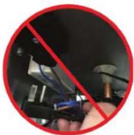
ELECTROCUTION HAZARD!! Never attempt to repair or perform maintenance on the unit until the Main electrical power has been disconnected.
Unplugging the condensing unit plug from the molded receptacle shown in the photo IS NOT sufficient to avoid electrical shock hazard. Disconnect power to the main unit by unplugging the main power cord from the wall receptacle or disable power to entire electrical circuit.

natural_image
Red circular background showing a hand holding a device with blue cables, no visible text or symbols.| PROBLEM CAUSE SOLUTION | ||
| Refrigerator does not run. | No power to the unit. | Check circuit protection devices. Fuses, breakers, GFI).Restore power to unit.Refer to information plate. See Section 1.0 and Table 7-1. |
| Incorrect control settings or faulty control. | Return to factory settings (see Sections 7.5.1 and 7.5.2) or replace control. | |
| Refrigerator is too warm. | Power | |
| No power to unit. | Restore power to unit.Refer to information plate. See Section 1.0 and Table 7-1. | |
| Incorrectly wired internal wiring connec-tions. | Verify wiring per wiring diagram. See Section 7.2.Reconnect wires if needed. | |
| Fans | ||
| Evaporator fan is not running. | Refer to Evaporator fan is not running | |
| Coils | ||
| Evaporator coil has iced over. Remove ice. | See Section 6.5 | |
| Condensing coil is not clean. Clean with soft brush and vacuum. | ||
| Fins are bent or damaged. Straighten fins. | ||
| Control | ||
| No power to control. Refer to Control not functioning | ||
| Control is not calling for cooling. Refer to Control not functioning | ||
| Probe failure. | Refer to Table 7-5 for resistance values. Replace probe if needed. See Section 7.5.4. | |
| Probe is not connected to the control. Reconnect probe. See Section 7.5.4. | ||
| Refrigerator is too warm. (continued) | Air Infiltration | |
| Sealing compound does not form a complete seal. | Refer to Section 1.1. | |
| Door gasket is damaged or out of place. | Refer to Sections 1.1 and 8.6. | |
| Condensate drain line/air trap is not positioned properly. | Reposition in loop. See Figure 6-3. | |
| Refrigerator is too cold. Incorrect control settings. | Return to factory settings.See Sections 7.5.1 and 7.5.2. | |
| Probe failure. | ||
| Control failure. | ||
| Refrigerator runs continuously. | Condensing coil is dirty. Clean with soft brush and vacuum. | |
| Incorrect control settings. | Return to factory settings.See Sections 7.5.1 and 7.5.2. | |
| Probe failure. | Refer to Table 7-5 for resistance values.Replace probe if needed. See Section 7.5.4. | |
| Evaporator coil has iced over. Remove ice per Section 6.5. | ||
| Sealing compound does not form a complete seal. | Refer to Section 1.1. | |
| Door gasket is damaged or out of place. Refer to Section 1.1 and 8.6. | ||
| Condensate drain line/air trap is not positioned properly. | Reposition in loop. See Figure 6-3. | |
| Extreme ambient conditions. Refer to Section 6.8. | ||
| Refrigeration/Charge level is too low. | Check for leaks, repair, and recharge per Section 6.13 and 6.16. | |
| Water on the floor outside of unit. | High ambient temperature and high ambient humidity conditions coupled with frequent door opening.Condensate pan overflowing. | Ensure doors close completely.Remove excess water.Check for the following:Air infiltration. See Section 6.1.Doors close completely and seals are intact. See Section 8.6.Ice buildup. See Section 6.5.Unit is running properly. Repair if needed. |
| Water on the floor outside of unit.(continued) | Unit is not level. Unit must be level front-to-back and side-to-side for water to drain properly. | |
| Sealing compound does not form a complete seal. | Refer to Section 1.1. | |
| Door gasket is damaged. Refer to Sections 1.1 and 8.6. | ||
| Remote ONLY: Floor drain plumbed incorrectly. | Check to make sure drain path makes sense. Refer to installation manual. | |
| Evaporator coil has iced over. Remove ice. | Refer to Section 6.5 | |
| Water on the floor inside of unit. | Evaporator pan and/or drain line restricted. | Remove restriction. |
| Unit is not level. | Unit must be level front-to-back and side-to-side for water to drain properly. | |
| Evaporator coil has iced over. Remove ice. | Refer to Section 6.5 | |
4.0 Troubleshooting Guide – Electrical System
DANGER
Unplugging the condensing unit plug from the molded receptacle shown in the photo IS NOT sufficient to avoid electrical shock hazard. Disconnect power to the main unit by unplugging the main power cord from the wall receptacle or disable power to entire electrical circuit.
natural_image
Red circular background with a hand holding a tool, no visible text or symbols| PROBLEM CAUSE SOLUTION | ||
| Compressor is not running. | No power to condensing unit. | Check condensing unit is plugged in. Check power at internal receptacle. |
| No call for cooling from control. Check control settings or for bad control. | ||
| Incorrectly wired connections in condensing unit. | Verify wiring per wiring diagram, Section 7.2. Reconnect wires if needed. | |
| Incorrect control settings. | Return to factory settings. See Sections 7.5.1 and 7.5.2. | |
| No power to compressor. | Restore power to unit. Refer to information plate. See Section 1.2 and Table 7-1. | |
| Faulty control. Refer to Control not functioning. | ||
| Models manufactured before March 2017: Starting device is not operational (start relay/capacitor).Models manufactured after March 2017: Starting device is not operational. | Models manufactured before March 2017: Replace compressor electrical components.Models manufactured after March 2017: Check Compressor Diagnostic 6.18. | |
| Faulty compressor. | Models manufactured before March 2017: Replace compressor per Section 6.14.Models manufactured after March 2017: Replace compressor per Section 6.14-6.16. | |
| Condenser fan is not running | No power to fan. | Restore power to unit. Refer to information plate. See Section 1.0 and Table 7-1. |
| Incorrectly wired harness. | Verify wiring per wiring diagram, Section 7.2. Reconnect wires if needed. | |
| Fan is obstructed. Remove obstructions. | ||
| Fan still does not run. Replace condenser fan per Section 6.13. | ||
| Evaporator fan is not running | No power to evaporator fan motor. | Restore power to unit. Refer to information plate. See Section 1.0 and Table 7-1 |
| Fan is obstructed. Remove obstruction. | ||
| Incorrectly wired harness. | Verify wiring per wiring diagram, Section 7.2. Reconnect wires if needed. | |
| If Evaporator fan is still not running... Replace evaporator fan per Section 6.13. | ||
| BBSLP series ONLY: No power to/from DC inverter/driver (12V). | If no power: restore power, replace. Refer to Section 1.1. | |
| Control not functioning | No power to unit. | Restore power to unit.Refer to information plate. See Section 1.0 and Table 7-1 |
| Incorrectly wired harness. | Verify wiring per wiring diagram, Section 7.2. Reconnect wires if needed. | |
| No call for cooling. | Replace controller | |
| Lights not functioning | Light switch in off position. | Turn on light switch. |
| No power to DC driver. | See unit info plate for voltage.Check output of DC driver (12V). | |
| No power to light switch. (12V) | Check wiring back to DC driver, replace if needed. | |
| Incorrectly wired lighting switch. | Verify wiring per wiring diagram, Section 7.2. Reconnect wires if needed. | |
| No power to LED strips? (12V) | Check wiring backwards to light switch. | |
| Faulty LED strip | Replace LED strip. | |
| Light stays on when door is closed. | Manual switch is on. Turn off manual switch. | |
| Eliwell Control: LED Controller display is flashing "E1" | Probe 1 error. Reading out-of-range of operating values. | Check probe connections to control. |
| Check probe resistance readings per Table 7-5. | ||
| Check probe wiring. | ||
| Replace probe per Section 7.5.3. | ||
| Eliwell Control: LED Controller display is flashing "AH1" | Probe 1 HIGH temperature alarm. | |
| Control | ||
| Incorrect control settings. | Return to factory settings.See 7.5.1 and 7.5.2. | |
| Power | ||
| Incorrectly wired harness. | Verify wiring per wiring diagram,Section 7.2. Reconnect wires if needed. | |
| Fans | ||
| Evaporator fan is not running. | Refer to Evaporator fan is not running. | |
| Coils | ||
| Evaporator coil has iced over. | Remove ice. See Section 6.5 | |
| Eliwell Control: LED Controller display is flashing "AH1" (continued) | Coils (continued) | |
| Condensing coil is not clean. | Clean with soft brush and vacuum. | |
| Fins are bent or damaged. | Straighten fins. | |
| Probe | ||
| Probe is not connected to control. | Reconnect probe.See Section 7.5.4. | |
| Air Infiltration | ||
| Sealing compound does not form a complete seal. | Refer to Section 1.1. | |
| Door gasket is damaged or not seated properly. | Refer to Section 1.1 and 8.6. | |
| Condensate drain line/air trap is not positioned properly. | Reposition in loop.See Control not functioning. | |
| Refrigeration/Charge level is too low. | Check for leaks, repair, and recharge.See Section 6.13 and 6.16.This is a critically charged system,recharging should only be done when all other options have been thoroughly checked. | |
| Eliwell Control: LED Controller display is flashing "AL1" | Probe 1 LOW temperature alarm. | |
| Incorrect control settings. | Return to factory settings.See Sections 7.5.1 and 7.5.2. | |
| Probe failure. | Refer to Table 7-5 for resistance values.Replace probe if needed.See Section 7.5.4. | |
| Control failure. Refer to Control not functioning | ||
| Dixell Control: LED Controller display is flashing "P1". | Probe failure. Contact dealer. | |
| Probe disconnected from control. Plug in probe connector. | ||
| Dixell Control: LED Controller display is flashing "HA". Maximum temperature alarm. | Internal compartment has exceeded the high temperature alarm preset value for over 30 minutes. | |
| Control | ||
| Incorrect control settings. | Return to factory settings.See Sections 7.5.1 and 7.5.2. | |
| Dixell Control: LED Controller display is flashing "HA". Maximum temperature alarm. (continued) | Power | |
| Incorrectly wired harness and/or internal wiring connections. | Verify wiring per wiring diagram, Section 7.2. Reconnect wires if needed. | |
| Fans | ||
| Evaporator fan is not running. | Refer to Evaporator fan is not running | |
| Coils | ||
| Evaporator coil has iced over. | Remove ice per Section 6.5. | |
| Condensing coil is not clean. | Clean with soft brush and vacuum. | |
| Fins are bent or damaged. | Straighten fins. | |
| Probe | ||
| Probe is not connected to the control. | Reconnect probe per Section 7.5.4. | |
| Air Infiltration | ||
| Sealing compound does not form a complete seal. | Refer to Section 1.1. | |
| Door gasket is damaged or out of place. | Refer to Section 1.1 and 8.6. | |
| Condensate drain line/air trap is not positioned properly. | Reposition in loop. See Figure 6-3. | |
| Refrigeration/Charge level is too low. | Check for leaks, repair, and recharge per Section 6.13 and 6.16.This is a critically charged system, recharging should only be done when all other options have been thoroughly checked. | |
| Dixell Control: LED Controller display is flashing "LA". Minimum temperature alarm. | Internal compartment has exceeded the low temperature alarm preset value for over 30 minutes. | |
| Incorrect control settings. | Return to factory settings.See 7.5.1 and 7.5.2. | |
| Probe failure. | Refer to Table 7-5 for resistance values.Replace probe if needed. See Section 7.5.4. | |
| Control failure. Refer to Control not functioning | ||
5.0 Troubleshooting Guide – Doors, Drawers and Shelving
| PROBLEM CAUSE SOLUTION | ||
| Key won't come out after door is locked. | Key not in proper position. | Rotate key to the proper position and remove. |
| Sliding doors not closing. | Replace spring and/or torpedo assembly. | Refer to Section 8.4.3. |
| Hinge problems, door falling off. | Improper door mounting | Verify proper mounting. Refer to Section 8-4. |
| Excessive wear | Replace worn parts.Refer to Section 8-4. | |
| Door handles falling off | Improper handle mounting | Verify proper mounting. Refer to diagram. |
| Excessive wear | Replace worn parts. Refer to diagram. | |
| Condensation on glass doors. | High ambient temperature, high humidity and environmental conditions. | Refer to Section 6.7. |
| Frequent door/drawer opening. | Refer to Section 8.1. | |
| Cabinet temperature too low. | Adjust temperature. Refer to Table 7-4. Factory Temperature Settings. | |
| Sliding doors dragging or binding | Debris in track. | Remove doorsClean tracks and lube with NSF approved food grade lube. |
6.0 Refrigeration System Repair Instructions
6.1 Air Infiltration
DANGER
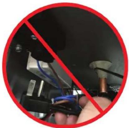
Unplugging the condensing unit plug from the molded receptacle shown in the photo IS NOT sufficient to avoid electrical shock hazard. Disconnect power to the main unit by unplugging the main power cord from the wall receptacle or disable power to entire electrical circuit.
natural_image
Close-up of a hand using a tool to switch electrical wiring, no text or symbols visibleSTEP 1. Door Gaskets
Check door gaskets for rips, cracks, or other damage.
The door gasket should be pushed in firmly and lay flat.
Ensure gasket forms a complete seal around door.
STEP 2. Sealing Compound
Sealing compound is used to seal wiring and line set pass-through between the condenser and the evaporator compartments. See Figure 6-1.
Check for voids and ensure sealing compound completely fills the space.
Figure 6-1.
Sealing Compound at Wiring
Pass-through

natural_image
Medical procedure image showing a patient undergoing a vascular graft with tubing and a glass container (no visible text or labels)STEP 3. Silicone Seal (RTV type)
Check for complete silicone seal of:
• Joint where rear wall meets ceiling
• Around evaporator coil compartment
STEP 4. Floor Drain
Check that interior floor drain plug is in place if not plumbed to external drain and completely tightened. Figure 6-2.
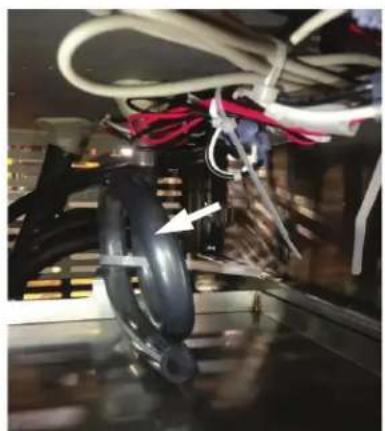
Check that the evaporator condensate trap is looped and full of water. Figure 6-3.

natural_image
Close-up of a metallic surface with circular holes and a white arrow pointing to a small dark spot (no text or symbols visible)Figure 6-2. Floor Drain
natural_image
Close-up of a mechanical assembly with visible wiring and a black component, no text or symbols present.Figure 6-3. Evaporator Condensate Trap
6.2 Slide Out the Refrigeration Deck
STEP 1.
Remove grille by removing 1 Phillips head screw at the top center grille and 2 at the bottom edge.
STEP 2.
Remove square bracket around the front of condensing unit by removing 6 Phillips screws and 2 hex head bolts. Figure 6-4
Pull the square bracket straight out.

natural_image
Close-up of a metallic industrial component with a grid-patterned internal structure and circular mounting holes (no text or symbols visible)Figure 6-4. Remove Condensing Unit Bracket
STEP 3.
The condensing unit/refrigeration deck can now be pulled straight out. Figure 6-5
Pull slowly and carefully to avoid damaging the copper line set.
- The copper line set is coiled with enough additional line to allow condensing unit to be removed from the cabinet.
- Do not place undue stress on copper lines when removing condensing unit.
- Damage/kinking of lines may occur if they are forcibly handled.

natural_image
Industrial cooling unit with coiled red heating elements and visible heat exchangers (no text or symbols)Figure 6-5. Removing Refrigeration Deck
6.3 Plumbing for Remote Drain
STEP 1.
Remove panel to gain access to the evaporator drip pan.
STEP 2.
Attach drain tube provided. See Figure 6-6.

natural_image
Technical line drawing of a mechanical assembly with a curved pipe and circular components (no text or symbols)Figure 6-6. Remote Drain Tube
CAUTION
Must be hooked up to an external floor drain, not floor inside unit or floor under unit.
6.4 System Operating Pressures
Note: To check operating pressures, you must gain access to the service valves. See Section 6.4.4.
6.4.1 First Time Pull-Down
After 7 minutes of intermediary speed, the speed is increased to maximum and it is kept at this rotation until the thermostat opens, switching the compressor off.
6.4.2 Normal Cycling
Compressor speed increases and decreases proportional to thermal load variation during compressor running time. Minimum speed will be targeted to minimize energy consumption.
6.4.3 Stabilization
If thermal load remains constant for a period longer than 20 minutes, the compressor speed is increased.
Note: The Compressor speed will be adjusted automatically by the Inverter, in accordance to the thermal load variation. (variable speed only)
Values in Table 6-1 represent a range of normal pressures. Themeasured pressure can vary depending on ambient conditions and at the point at which unit is in the refrigeration cycle.
Table 6-1. System Operating Pressures
| RUNNING PRESSURE | |
| Low Side 15-20 PSIG | |
| High Side 120-180 PSIG |
6.4.4 Service Valves
STEP 1.
Remove the refrigeration deck (see Section 6.2), See Figure 6-5.
STEP 2.
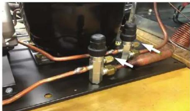
Remove black caps. See Figure 6-7.
STEP 3. Recording pressure
When installing gauges:
- Initially purge manifold set with refrigerant type used in unit. This avoids introduction of air into system.
- Crack valve off back seat position to read pressures.
- Allow unit to run for 10 minutes and stabilize before recording pressures.
When disconnecting hoses:
- Initially back seat the high side service valve.
- Open manifold on gauges to place high side liquid back into system and equalize gauges.
- Then back seat low side service valve and remove gauges.
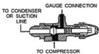
Service valve positions are as follows:
Fully Left Back seated with flow from refrigeration system closed.
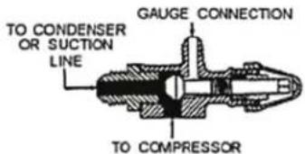
Middle Allows flow from the refrigeration system to the service port.

Fully Right Front seated with flow to the service port closed.
natural_image
Industrial equipment setup with copper pipes and valves, no visible text or symbolsFigure 6-7. Service Valves
6.5 De-Ice Blocked Evaporator Coil – Self-Contained Models
STEP 1.
Remove shelves and pilaster from refrigerator section nearest the evaporator coil.
STEP 2.
Remove Evaporator Fan panel by removing 7 Phillips head screws from perimeter of panel. See Figure 6-8.

natural_image
Interior view of a server rack with ventilation ducts and mounting holes (no visible text or symbols)Figure 6-8. Removing Evaporator Fan Panel
STEP 3.
Pull the handle and panel straight out from inner wall. The panel and connected fan can be placed on floor of cabinet.
STEP 4.
Using a fan or heat gun to gently direct warm air over ice to remove.
CAUTION
DO NOT use any tools to chip at or physically remove ice!
STEP 5. When ice has been removed:
Check sealing compound. Re-forming, if necessary, to close any gaps around wire harness and piping.
Check for other potential sources of air infiltration. See Section 6.1.
STEP 6.
Reverse steps 1 through 3 to close the evaporator fan panel.
6.6 Air Flow Obstructions
The unit must have free air flow to front grille to operate properly.
Restricted air flow results in high head pressures and reduction in efficiency due to longer run times.
Proper air flow around condensing unit and evaporator is necessary for efficient operation.
- Never obstruct air flow in and out of condensing unit.
- The front grille must be free from obstructions, dust, and debris.
- Never obstruct air flow to Evaporator Fan.
- Make sure higher temperature ambient air from another unit is not directed to condenser coil (i.e. another condensing unit directly across from the unit).
- Never place items in the area behind Product Side Guard/Handle. See Figure 6-9.

Figure 6-9. Check for Obstructions
6.7 Clean Condenser Coil
DANGER
ELECTROCUTION HAZARD!! Never attempt to repair or perform maintenance on the unit until the Main electrical power has been disconnected.
Perlick's warranty does not cover cleaning of condenser.
The condenser is located directly behind the front grille. See Figure 6-4.
Condenser coils that are covered with dust and debris restrict air flow. This results in high head pressures and lower efficiency due to longer run times.
Use soft brush and vacuum to clean coil every 90 days, or more often if conditions require.
6.8 Ambient Temperature
High ambient temperature and high humidity conditions may result in performance issues and/or refrigeration system failure.
The unit must be protected from precipitation.
Do not subject to direct solar load.
Under extreme temperature and/or relative humidity conditions the front face, gasket and/or glass door may show signs of condensation. When temperature and/or relative humidity conditions return to normal condensation will disappear.
6.10 Compressors and Condensing Unit (units shipped pre 3-27-2017 only)
Table 6-2. Compressor Data
| MODEL / FAMILY HP | WIRING | START WINDING RESISTANCE Ω AT 77°F | RUN WINDING RESISTANCE Ω AT 77°F | RUN/START | |
| BBS36 1/5 | RSIR 8.85 | 3.85 12.70 | |||
| BBS60 1/4 | CSIR 4.15 | 1.55 5.70 | |||
| BBS84 1/3 | CSIR 3.87 | 1.04 4.91 | |||
| BBS108 1/3 | CSIR 3.87 | 1.04 4.91 | |||
| BBSN32 1/5 | RSIR 8.85 | 3.85 12.70 | |||
| BBSN52 1⁄4 | CSIR 4.15 | 1.55 5.70 | |||
| BBSN72 1/3 | CSIR 3.87 | 1.04 4.91 | |||
| BBSN92 1/3 | CSIR 3.87 | 1.04 4.91 | |||
| PTS36 1/5 | RSIR 8.85 | 3.85 12.70 | |||
| PTS60 1/4 | CSIR 4.15 | 1.55 5.70 | |||
| PTS84 1/3 | CSIR 3.87 | 1.04 4.91 | |||
| DZS36 1/5 | RSIR 8.85 | 3.85 12.70 | |||
| DZS60 1/4 | CSIR 4.15 | 1.55 5.70 | |||
| SDBS60 1/4 | CSIR 4.15 | 1.55 5.70 | |||
| SDBS108 | 1/3 CSIR | 3.87 1.04 | 4.91 | ||
| SDPS60 | 1/4 CSIR | 4.15 1.55 | 5.70 | ||
| BBSLP36 | 1/5 RSIR | 8.85 3.85 | 12.70 | ||
| BBSLP60 1⁄4 | CSIR 4.15 | 1.55 5.70 | |||
| BBSLP84 | 1/3 CSIR | 3.87 1.04 | 4.91 | ||
| BBSLP108 | 1/3 CSIR | 3.87 1.04 | 4.91 | ||
| DDC68 1/4 | CSIR 4.15 | 1.55 5.70 | |||
| DDC92 1/3 | CSIR 3.87 | 1.04 4.91 | |||
| DDS36 1/5 | RSIR 8.85 | 3.85 12.70 | |||
| DDS60 1/4 | CSIR 4.15 | 1.55 5.70 | |||
| DDS84 1/3 | CSIR 3.87 | 1.04 4.91 | |||
| DDS108 | 1/3 CSIR | 3.87 1.04 | 4.91 |
6.12 Replace Condenser Fan Motor
STEP 1.
Remove Refrigeration Deck. See Section 6.2.
STEP 2.
Unplug the fan power cord from beneath electrical box on compressor.
STEP 3.
Remove fan motor assembly by removing 4 Phillips head screws that hold the fan bracket.

natural_image
Close-up of an appliance with visible wiring and a mounted fan assembly (no text or symbols)Figure 6-10. Fan Mounting Hardware
STEP 4.
Install new fan motor assembly by attaching the bracket with 4 screws.
STEP 5.
Install refrigeration deck by reversing steps in section 6.2.
6.13 Replace Evaporator Fan Motor – Self-Contained Models
STEP 1.
Remove grille by removing 3 Phillips head screws, one at the top center and two at the bottom edge.
STEP 2.
Cut 2 zip ties holding wire harness to top of the refrigeration module.
STEP 3.
Disconnect evaporator fan wire leads from main wiring harness.
STEP 4.
Remove sealing compound from top and bottom of wire pass-through located inside evaporator box and inside of machine compartment.
STEP 5.
Remove shelving from unit, as well as shelf bracket on left wall.
STEP 6.
Remove 7 screws holding evaporator fan panel to unit. Figure 8-7
STEP 7.
Tip evaporator fan assembly down and remove from unit. Pull evaporator fan wires up though the top of the machine compartment.
STEP 8.
Remove 8 screws to separate front and back of evaporator fan panel.

natural_image
Close-up of a black electronic device with visible cooling fins and mounting holes, no text or symbols present.STEP 9.
Remove 8 fan mounting screws.

natural_image
Close-up of a mechanical fan or impeller component with multiple blades and mounting holes (no visible text or symbols)STEP 10.
Evaporator fan motor can now be replaced. Evaporator fan motor should only be replaced with Perlick OEM parts.
STEP 11.
Reverse steps 1-9 to close the unit.
6.14 Replace Compressor
To gain access to compressor, follow instructions in Section 6.2.
Compressor should only be replaced with Perlick OEM parts.
Always replace drier when replacing compressor.
6.15 Leak Detection
If during a check of operating system pressures, it is determined that refrigerant level is low, you must perform a leak test.
- Do not recharge a system without first determining where original refrigerant charge exited the sealed system!
-
Placing a system that has lost refrigerant under a vacuum without first repairing the leak will draw contaminants into the system through the point of leak. Find source of the leak and correct it!
-
The use of an electronic leak detector is highly encouraged.
- If the entire charge has leaked out of the unit, the sealed system should be pressurized with 200 lbs. of dry nitrogen and tracer refrigerant. Then use an ultrasonic leak detector or a soap and water solution to pinpoint the location of the leak.
- Be certain to check all brazed connections thoroughly for leaks. Look for spots where the sealed system components might have been worn through by structural or cabinet components.
- Check the service ports thoroughly for leaks as well.
6.16 Recharge Procedure
STEP 1.
Check that the system been properly installed, pressure tested, and evacuated.
STEP 2.
Condenser and evaporator must be clean. Evaporator fan and condenser fan blades must be able to move the correct amount of air.
STEP 3.
Before installing gauges, vent hoses and manifold with refrigerant type used in unit. This avoids introduction of air into system.
Continue to next page...
STEP 4.
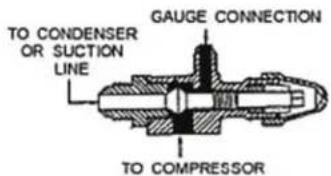
Service valve positions are as follows:
Fully Left Back seated with flow from refrigeration system closed.

Middle Allows flow from the refrigeration system to the service port.
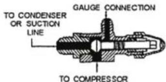
Fully Right Front seated with flow to the service port closed.
STEP 5.
Charge level is listed on unit information plate.
CAUTION
Once charge level has been set, avoid installing gauges as part of regular service. System should be kept sealed.
Do not "top off" or add refrigerant to an unknown existing charge.
Completely reclaim existing refrigerant in accordance with EPA regulations and thoroughly evacuate the system.
After evacuating the system:
-
Break vacuum with refrigerant.
-
Purge system through the high side until a nominal amount of refrigerant is purged out of the low side.
- Then "weigh in" the correct total charge into system.
6.17 Replace compressor starting device – Self-contained models
STEP 1.
Completely slide out refrigeration deck. See Section 6.2.
STEP 2.
Pry open gray cover. Starting device is now accessible.

natural_image
Close-up of a mechanical device with a tool inserted, showing no visible text or symbols.Overload device and capacitor are also accessible.

6.18 Troubleshooting Guide – Refrigeration System: Variable Speed Compressor\*
*For Models beginning in March 2017
Use this diagnostic guide to identify issues and to locate applicable instructions within this service manual. This diagnostic guide can be used for any of Perlick's Back Bar Refrigeration Products.
DANGER
ELECTROCUTION HAZARD!!
Never attempt to repair or perform maintenance on the unit until the Main electrical power has been disconnected.
| PROBLEM CAUSE SOLUTION | ||
| Refrigerator does not run. | No power to the unit. Check circuit protection | devices. Fuses, breakers, GFI).Restore power to unit.Refer to information plate. See Section 1.0 and Table 7-1. |
| Failed Compressor | See Compressor Test Procedures | |
6.18.1 Compressor/Inverter Test Procedures
Electrical Connections: The compressor IS NOT 100% controlled from the internal wiring block, as in previous models
- DO NOT attempt to test the compressor or inverter with the main plug or inverter power wire energized.

natural_image
Close-up of mechanical components with wires and a red diagonal line overlay (no visible text or symbols)Electrical Meters: Volumeters WILL NOT be able to read the voltage output from the inverter.
Power Visual Review: The Inverter is equipped with LED lights indicating electrical power and performance.
6.18.2 Compressor Diagnostic
Resistance Readings:
The following should be read between any 2 of 3 pins.
| Compressor Resistance (OHMS) | |
| VEG8TU 10.5 | |
| VEGT11HB 6.0 | |
6.18.3 Inverter Diagnostic
Accessing the Inverter
STEP 1.
Locate the LED Dianostics, which can be viewed from the rear of the unit.
STEP 2.
Remove the grill and view the amber cover located on the inverter.
NOTE: It is not necessary to remove the cover for viewing
Inverter Flash Codes
| LED Status | Period Between Flash | Description |
| 1 Green Flash 30 | sec Normal | Operation |
| 4 Green Flashes 5 | sec Communications Problem | |
| 4 Red Flashes 5 | sec Inverter | Problem |
| 4 Orange Flashes | 5 sec Compressor Problem | |
6.18.4 Variable Speed Compressor Change
Compressor Change Procedures:
See Section 6.14-6.16
Wiring Connections
CAUTION
When replacing compressor/inverter, ensure the unit is wired correctly.
Ensure the purple inverter wire is connected to the main power harness wiring, containing the UL reference.

natural_image
Close-up of electronic components with colored wires and connectors, no visible text or symbols6.18.5 Troubleshooting
(After Compressor Replacement)
| Problem Cause Solution | ||
| Compressor is not running. | Inverter Code Flash (4 Green flashes, 5 second-intervals) | Incorrectly wired;Check that purple wire is connected correctly |
7.0 Electrical System Repair Instructions
7.1 Electrical Specifications (units shipped pre 3-27-2017 only)
Verify adequate power is supplied.
To avoid electrical shock, completely disconnect electrical power to referenced units before performing service work. Disconnect power to entire unit by unplugging the main power cord from the wall receptacle or disabling power to the circuit at the electrical circuit protection device, (i.e. circuit breaker).

natural_image
Red circular icon showing a hand holding a tool, no text or symbols visibleTable 7-1. Electrical Specifications
| Unit Type | Model Number | Running Load Amps | Electrical Supply | Electrical Connection |
| Self-Contained | BBS36 | 3.2 | 120 VAC/60 Hz/1 Ph | Cord Connected |
| BBS60 | 5.5 | |||
| BBS84 | 6.3 | |||
| BBS108 | 6.3 | |||
| BBSLP36 3.0 | ||||
| BBSLP60 5.3 | ||||
| BBSLP84 6.7 | ||||
| BBSLP108 | 6.7 | |||
| BBSN32 | 3.2 | |||
| BBSN52 | 5.5 | |||
| BBSN72 | 6.3 | |||
| BBSN92 | 6.3 | |||
| DDS36 3.2 | ||||
| DDS60 5.5 | ||||
| DDS84 6.3 | ||||
| DDS108 | 6.3 | |||
| DDC68 | 5.5 | |||
| DDC92 | 6.3 | |||
| DZS36 3.2 | ||||
| DZS60 | 5.5 | |||
| PTS36 | 3.2 | |||
| PTS60 | 5.5 | |||
| PTS84 | 6.3 | |||
| SDBS60 5.5 | ||||
| SDBS108 | 6.3 | |||
| SDPS60 | 5.5 | |||
| Remote | BBR24 | 1.1 | 120 VAC/60 Hz/1 Ph | Hard Wired |
| BBR48 | 1.6 | |||
| BBR72 | 2 | |||
| BBR96 | 2.5 | |||
| BBRLP48 1.6 | ||||
| BBRLP72 2 | ||||
| BBRLP96 | 2.5 | |||
| BBRN40 | 1.6 | |||
| BBRN60 | 2 | |||
| BBRN80 | 2.5 | |||
| PTR48 1.6 | ||||
| PTR72 | 2 | |||
| SDBR48 | 1.6 | |||
| SDBR96 | 2.5 | |||
| SDPR48 | 1.6 |
7.2 Wiring Diagrams

flowchart
graph TD
    A["12VDC POWER SUPPLY"] -->|BROWN| B["1st DOOR LED BOARD"]
    B -->|BLACK| C["2nd DOOR LED BOARD"]
    C --> D["MULLION HEATER"]
    E["EVAPORATOR FAN"] -->|WHITE| F["Black"]
    F --> G["CABINET JUNCTION BOX"]
    G --> H["POWER CONNECTION"]
    H --> I["PRESSURE SWITCH"]
    I --> J["CONDENSING UNIT"]
    J --> K["NOTE: FIELD WIRING FROM CABINET JUNCTION BOX TO CONDENSING UNIT MUST COMPLY WITH ALL LOCAL AND NATIONAL ELECTRICAL CODES"]
    style A fill:#f9f,stroke:#333
    style B fill:#ccf,stroke:#333
    style C fill:#cfc,stroke:#333
    style D fill:#fcc,stroke:#333
    style E fill:#cff,stroke:#333
    style F fill:#ffc,stroke:#333
    style G fill:#cfc,stroke:#333
    style H fill:#fcc,stroke:#333
    style I fill:#ffc,stroke:#333
    style J fill:#cfc,stroke:#333
    style K fill:#fcc,stroke:#333
Figure 7-1. BBR24, BBRN40 Wiring Diagram

flowchart
graph TD
    A["12VDC POWER SUPPLY"] -->|BROWN| B["12VDC OUTPUT RED"]
    B -->|BLACK| C["LIGHT SWITCH"]
    C -->|RED| D["1st DOOR LED BOARD"]
    D -->|BLACK| E["MULLION HEATER"]
    F["WHITE"] --> G["BBR24"]
    H["BLACK"] --> I["EVAPORATOR FAN"]
    J["POWERS CONNECTION"] --> K["PRESSURE SWITCH"]
    L["CABINET JUNCTION BOX"] --> M["CONDENSING UNIT"]
    N["THESE WIRES CAPPED IN SINGLE CABINET INSTALLATIONS"] --> O["NOTE: FIELD WIRING FROM CABINET JUNCTION BOX TO CONDENSING UNIT MUST COMPLY WITH ALL LOCAL AND NATIONAL ELECTRICAL CODES"]
Figure 7-1. BBR24, BBRN40 Wiring Diagram

flowchart
graph TD
    A["PRODUCTION START: NA\nPRODUCTION END: 3/26/2017"] --> B["12VDC POWER SUPPLY"]
    B --> C["12VDC OUTPUT RED"]
    C --> D["LIGHT SWITCH"]
    D --> E["1st DOOR LED BOARD"]
    E --> F["2nd DOOR LED BOARD"]
    F --> G["3rd DOOR LED BOARD"]
    G --> H["4th DOOR LED BOARD"]
    B --> I["EVAPORATOR FAN"]
    I --> J["EVAPORATOR FAN"]
    J --> K["CABINET JUNCTION BOX"]
    K --> L["THES WIRE CAPCDED IN SINGLE CABINET INSTALLATIONS"]
    L --> M["TYPICAL FIELD INSTALLATION"]
    M --> N["PRESSURE SWITCH"]
    N --> O["CONDENSING UNIT"]
    O --> P["NOTE: FIELD WIRING FROM CABINET JUNCTION BOX TO CONDENSING UNIT MUST COMPLY WITH ALL LOCAL AND NATIONAL ELECTRICAL CODES"]
    style A fill:#f9f,stroke:#333
    style B fill:#ccf,stroke:#333
    style C fill:#cfc,stroke:#333
    style D fill:#fcc,stroke:#333
    style E fill:#cff,stroke:#333
    style F fill:#ffc,stroke:#333
    style G fill:#ffc,stroke:#333
    style H fill:#ffc,stroke:#333
    style I fill:#fcc,stroke:#333
    style J fill:#fcc,stroke:#333
    style K fill:#fcc,stroke:#333
    style L fill:#fcc,stroke:#333
    style M fill:#ffc,stroke:#333
    style N fill:#ffc,stroke:#333
    style O fill:#ffc,stroke:#333
    style P fill:#ffc,stroke:#333
Figure 7-2. BBR48, BBR72, BBR96, BBRN60, BBRN80 Wiring Diagram

flowchart
graph TD
    A["120VAC INPUT BLUE"] --> B["12VDC POWER SUPPLY"]
    B --> C["EVAPORATOR FAN"]
    C --> D["BLACK"]
    D --> E["1st DOOR LED BOARD"]
    E --> F["BLACK"]
    F --> G["2nd DOOR LED BOARD"]
    G --> H["BLACK"]
    H --> I["3rd DOOR LED BOARD"]
    I --> J["BLACK"]
    J --> K["4th DOOR LED BOARD"]
    K --> L["BLACK"]
    L --> M["3rd MULLION HEATER"]
    M --> N["BLACK"]
    N --> O["2nd MULLION HEATER"]
    O --> P["BLACK"]
    P --> Q["3rd MULLION HEATER"]

    R["12VDC OUTPUT RED"] --> S["BLACK"]
    T["1st DOOR LED BOARD"] --> U["BLACK"]
    V["2nd DOOR LED BOARD"] --> W["BLACK"]
    X["3rd DOOR LED BOARD"] --> Y["BLACK"]

    Z["TYPICAL FIELD INSTALLATION"]
    AA["CABINET JUNCTION BOX"] --> AB["BLACK"]
    AC["WHITE"] --> AD["BLACK"]
    AE["RED"] --> AF["GREEN"]
    AG["THESE WIRES CAPPED IN SINGLE CABINET INSTALLATIONS"] --> AH["BLACK"]

    AI["BBR48"] --> AJ["1st MULLION HEATER"]
    AK["BBRN60 & BBR72"] --> AL["1st MULLION HEATER"]
    AM["BBRN80 & BBR96"] --> AN["1st MULLION HEATER"]

    AO["PRESSURE SWITCH"] --> AP["CONDENSING UNIT"]

    AQ["POWER CONNECTION"] --> AR["BLACK WHITE GREEN"]

    AS["FORMS"] --> AT["Black"]

    AU["NOTE: FIELD WIRING FROM CABINET JUNCTION BOX TO CONDENSING UNIT MUST COMPLY WITH ALL LOCAL AND NATIONAL ELECTRICAL CODES"]
Figure 7-2. BBR48, BBR72, BBR96, BBRN60, BBRN80 Wiring Diagram

flowchart
graph TD
    A["NEMA 5-15P"] --> B["MOLDED RECEPTACLE"]
    B --> C["RED"]
    B --> D["BLACK"]
    B --> E["WHITE"]
    B --> F["GREEN"]
    B --> G["RED"]
    B --> H["BLACK"]
    B --> I["12VDC POWER SUPPLY"]
    B --> J["120VAC INPUT"]
    B --> K["BROWN"]
    B --> L["BLUE"]
    B --> M["WHITE"]
    B --> N["BLACK"]
    B --> O["RED"]
    O --> P["LED BOARD 1st DOOR"]
    P --> Q["BBS36 BBS36C BBSN32"]
    P --> R["BBS60 BBSN52"]
    P --> S["BBS84 BBSN72"]
    P --> T["BBS108 BBSN92"]
    P --> U["BBS SERIES - DRAWER MULLION HEATER(S) CAN BE CONNECTED TO ANY HEATER JUNCTION(S) BASED ON CUSTOMER OPTIONS."]
    P --> V["DRAWER MULLION HEATER"]
    P --> W["EVAPORATOR FAN"]
    P --> X["SENSING PROBE"]
    P --> Y["CONDENSING UNIT"]
    P --> Z["LED SWITCH"]
    P --> AA["BLACK"]
    P --> AB["BLACK"]
    P --> AC["BLACK"]
    P --> AD["BLACK"]
    P --> AE["Black"]
    P --> AF["Black"]
    P --> AG["Black"]
    P --> AH["Black"]
    P --> AI["Black"]
    P --> AJ["Black"]
    P --> AK["Black"]
    P --> AL["Black"]
    P --> AM["Black"]
    P --> AN["Black"]
Figure 7-3. BBS36, BBS60, BBS84, BBS108, BBSN32, BBSN52, BBSN72, BBSN92 Wiring Diagram

flowchart
graph TD
    A["PRODUCTION START: 3/27/2017"] --> B["PRODUCTION END: N/A"]
    B --> C["INVERTER"]
    C --> D["CONDENSING UNIT 2, 3, 4 DOOR ONLY"]
    D --> E["12VDC POWER SUPPLY"]
    E --> F["12VDC OUTPUT"]
    F --> G["BACK"]
    G --> H["1st DOOR LED BOARD"]
    H --> I["BBS36 BBS36C BBSN32"]
    H --> J["BBS60 BBSN52"]
    H --> K["BBS84 BBSN72"]
    H --> L["BBS108 BBSN92"]
    H --> M["BBS SERIES - DRAWER MULLION HEATER(S) CAN BE CONNECTED TO ANY HEATER JUNCTION(S) BASED ON CUSTOMER OPTIONS."]
    M --> N["DRAWER MULLION HEATER"]
    M --> O["EVAPORATOR FAN"]
    M --> P["SENSING PROBE"]
    M --> Q["CONDENSING UNIT 1 DOOR ONLY"]
    Q --> R["CONDENSING UNIT 1 DOOR ONLY"]
    R --> S["MOLDED RECEPTACLE"]
    S --> T["NEMA 5-15P"]
    T --> U["CONNECT CONDENSING UNIT HERE"]
    U --> V["BACK"]
    V --> W["RED BLACK WHITE"]
    W --> X["GREEN"]
    X --> Y["MOLDED RECEPTACLE"]
    Y --> Z["BACK"]
    Z --> AA["RED BLACK WHITE"]
    AA --> AB["RED BLACK WHITE"]
    AB --> AC["RED BLACK WHITE"]
    AC --> AD["RED BLACK WHITE"]
    AD --> AE["RED BLACK WHITE"]
    AE --> AF["RED BLACK WHITE"]
    AF --> AG["RED BLACK White"]
    AG --> AH["RED BLACK White"]
    AH --> AI["RED BLACK White"]
    AI --> AJ["RED BLACK White"]
    AJ --> AK["RED BLACK White"]
    AK --> AL["RED BLACK White"]
    AL --> AM["RED BLACK White"]
    AM --> AN["RED BLACK White"]
    AN --> AO["RED BLACK White"]
    AO --> AP["RED BLACK White"]
    AP --> AQ["RED BLACK White"]
    AQ --> AR["RED BLACK White"]
    AR --> AS["RED BLACK White"]
    AS --> AT["RED BLACK White"]
    AT --> AU["RED BLACK White"]
    AU --> AV["RED BLACK White"]
    AV --> AW["RED BLACK White"]
    AW --> AX["RED BLACK White"]
    AX --> AY["RED BLACK White"]
Figure 7-3. BBS36, BBS60, BBS84, BBS108, BBSN32, BBSN52, BBSN72 and BBSN92 Wiring Diagram

flowchart
graph TD
    A["PRODUCTION START: 9/19/2016"] --> B["PRODUCTION END: N/A"]
    B --> C["12VDC POWER SUPPLY"]
    C --> D["12VDC OUTPUT"]
    D --> E["1st DOOR LED BOARD"]
    E --> F["BBS36 BBS36C BBSN32"]
    E --> G["BBS60 BBSN52"]
    E --> H["BBS84 BBSN72"]
    E --> I["BBS108 BBSN92"]
    E --> J["1st MULLION HEATER"]
    E --> K["2nd MULLION HEATER"]
    E --> L["3rd MULLION HEATER"]
    C --> M["230VAC INPUT"]
    M --> N["O&R"]
    M --> O["O&R"]
    M --> P["O&R"]
    M --> Q["O&R"]
    M --> R["O&R"]
    M --> S["O&R"]
    M --> T["O&R"]
    M --> U["O&R"]
    M --> V["O&R"]
    M --> W["O&R"]
    M --> X["O&R"]
    M --> Y["O&R"]
    M --> Z["O&R"]
    M --> AA["O&R"]
    M --> AB["O&R"]
    M --> AC["O&R"]
    M --> AD["O&R"]
    M --> AE["O&R"]
    M --> AF["O&R"]
    M --> AG["O&R"]
    M --> AH["O&R"]
    M --> AI["O&R"]
    M --> AJ["O&R"]
    M --> AK["O&R"]
    M --> AL["O&R"]
    M --> AM["O&R"]
    M --> AN["O&R"]
    M --> AO["O&R"]
    M --> AP["O&R"]
    M --> AQ["O&R"]
    M --> AR["O&R"]
    M --> AS["O&R"]
    M --> AT["O&R"]
    M --> AU["O&R"]
    M --> AV["O&R"]
    M --> AW["O&R"]
    M --> AX["O&R"]
    M --> AY["O&R"]
    M --> AZ["O&R"]
    M --> BA["O&R"]
    M --> BB["O&R"]
    M --> BC["O&R"]
    M --> BD["O&R"]
    M --> BE["O&R"]
    M --> BF["O&R"]
    M --> BG["O&R"]
    M --> BH["O&R"]
    M --> BI["O&R"]
    M --> BJ["O&R"]
    M --> BK["O&R"]
    M --> BL["O&R"]
    M --> BM["O&R"]
    M --> BN["O&R"]
    M --> BO["O&R"]
    M --> BP["O&R"]
    M --> BQ["O&R"]
    M --> BR["O&R"]
    M --> BS["O&R"]
    M --> BT["O&R"]
    M --> BU["O&R"]
    M --> BV["O&R"]
    M --> BW["O&R"]
    M --> BX["O&R"]
    M --> BY["O&R"]
    M --> BZ["O&R"]
    M --> CA["O&R"]
    M --> CB["O&R"]
    M --> CC["O&R"]
    M --> CD["O&R"]
    M --> CE["O&R"]
    M --> CF["O&R"]
    M --> CG["O&R"]
    M --> CH["O&R"]
    M --> CI["O&R"]
    M --> CJ["O&R"]
    M --> CK["O&R"]
    M --> CL["O&R"]
    M --> CM["O&R"]
    M --> CN["O&R"]
    M --> CO["O&R"]
    M --> CP["O&R"]
    M --> CQ["O&R"]
    M --> CR["O&R"]
    M --> CS["O&R"]
    M --> CT["O&R"]
    M --> CU["O&R"]
    M --> CV["O&R"]
    M --> CW["O&R"]
    M --> CX["O&R"]
    M --> CY["O&R"]
    M --> CZ["O&R"]
Figure 7-4. BBS36, BBS60, BBS84, BBS108, BBSN32, BBSN52, BBSN72 and BBSN92 Wiring Diagram

flowchart
graph TD
    A["120VAC INPUT BLUE"] --> B["12VDC POWER SUPPLY"]
    B --> C["BLACK"]
    C --> D["12VDC OUTPUT RED"]
    D --> E["BLACK"]
    E --> F["LIGHT SWITCH"]
    F --> G["BLACK"]
    G --> H["1st DOOR LED BOARD"]
    H --> I["BLACK"]
    I --> J["2nd DOOR LED BOARD"]
    J --> K["MULLION HEATER"]
    L["WHITE"] --> M["BLACK"]
    N["WHITE"] --> O["BLACK"]
    P["EVAPORATOR FAN"] --> Q["BLACK"]
    R["CABINET JUNCTION BOX"] --> S["BLACK"]
    T["Black"] --> U["RED"]
    V["THESE WIRES CAPPED IN SINGLE CABINET INSTALLATIONS"] --> W["GREEN"]
    X["TYPICAL FIELD INSTALLATION"] --> Y["PRESSURE SWITCH"]
    Y --> Z["BLACK"]
    AA["POWER CONNECTION"] --> AB["WHITE GREEN"]
    AC["CONDENSING UNIT"] --> AD["GREEN"]
    AE["NOTE: FIELD WIRING FROM CABINET JUNCTION BOX TO CONDENSING UNIT MUST COMPLY WITH ALL LOCAL AND NATIONAL ELECTRICAL CODES"] --> AF["PRODUCTION START: NA"]
    AG["PRODUCTION END: 03/26/2017"] --> AH["PRODUCTION START: NA"]
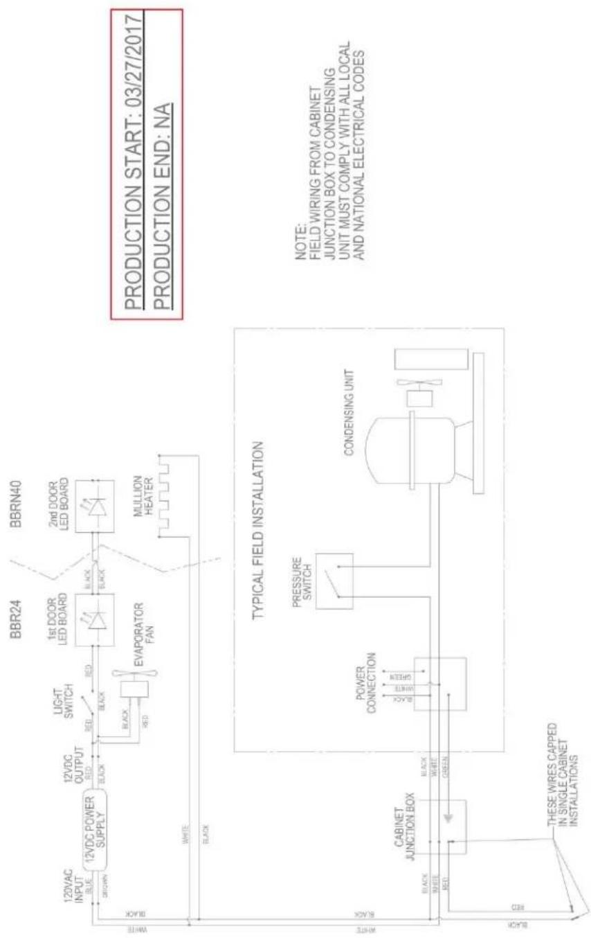
Figure 7-4. BBR24, BBRN40 Wiring Diagram
flowchart
graph TD
    A["120VAC INPUT"] --> B["12VDC POWER SUPPLY"]
    B --> C["12VDC OUTPUT RED"]
    C --> D["BLACK"]
    D --> E["1st DOOR LED BOARD"]
    E --> F["BLACK"]
    F --> G["MULLION HEATER"]
    H["BBR24"] --> I["1st DOOR LED BOARD"]
    I --> J["BLACK"]
    J --> K["MULLION HEATER"]
    L["BBRN40"] --> M["2nd DOOR LED BOARD"]
    M --> N["BLACK"]
    N --> O["MULLION HEATER"]

    P["WHITE"] --> Q["BLACK"]
    R["WHITE"] --> S["BLACK"]

    T["TYPICAL FIELD INSTALLATION"] --> U["CABINET JUNCTION BOX"]
    U --> V["BLACK"]
    V --> W["WHITE"]
    V --> X["GREEN"]

    Y["PRESSURE SWITCH"] --> Z["POWER CONNECTION"]
    Z --> AA["BLACK"]
    AA --> AB["WHITE"]
    AA --> AC["GREEN"]

    AD["CONDENSING UNIT"] --> AE["Black Box"]
    AE --> AF["RED"]

    AG["NOTE: FIELD WIRING FROM CABINET, JUNCTION BOX TO CONDENSING, UNIT MUST COMPLY WITH ALL LOCAL, AND NATIONAL ELECTRICAL CODES"] --> AH["Red"]
    AI["THESE WIRES CAPPED IN SINGLE CABINET INSTALLATIONS"] --> AJ["Black Box"]
Figure 7-5. BBR24, BBRN40 Wiring Diagram

flowchart
graph TD
    A["PRODUCTION START: NA\nPRODUCTION END: 3/26/2017"] --> B["12VDC POWER SUPPLY"]
    B --> C["12VDC OUTPUT RED"]
    C --> D["1st DOOR LED BOARD"]
    D --> E["2nd DOOR LED BOARD"]
    E --> F["3rd DOOR LED BOARD"]
    F --> G["4th DOOR LED BOARD"]
    B --> H["EVAPORATOR FAN"]
    H --> I["EVAPORATOR FAN"]
    I --> J["CABINET JUNCTION BOX"]
    J --> K["THESE WIRE CAPTED IN SINGLE CABINET INSTALLATIONS"]
    D --> L["BBR48"]
    E --> M["BBRN60 & BBR72"]
    F --> N["BBRN80 & BBR96"]
    G --> O["1st MULLION HEATER"]
    G --> P["2nd MULLION HEATER"]
    G --> Q["3rd MULLION HEATER"]
    J --> R["POWER CONNECTION"]
    J --> S["PRESSURE SWITCH"]
    J --> T["CONDENSING UNIT"]
    style A fill:#f9f,stroke:#333
    style B fill:#ccf,stroke:#333
    style C fill:#cfc,stroke:#333
    style D fill:#fcc,stroke:#333
    style E fill:#cff,stroke:#333
    style F fill:#ffc,stroke:#333
    style G fill:#fcf,stroke:#333
    style H fill:#fff,stroke:#333
    style I fill:#fff,stroke:#333
    style J fill:#fff,stroke:#333
    style K fill:#fff,stroke:#333
    style L fill:#fff,stroke:#333
    style M fill:#fff,stroke:#333
    style N fill:#fff,stroke:#333
    style O fill:#fff,stroke:#333
    style P fill:#fff,stroke:#333
    style Q fill:#fff,stroke:#333
    style R fill:#fff,stroke:#333
    style S fill:#fff,stroke:#333
    style T fill:#fff,stroke:#333
Figure 7-5. BBR48, BBR72, BBR96, BBRN60 and BBRN80 Wiring Diagram

flowchart
graph TD
    A["12VDC POWER SUPPLY"] -->|BROWN| B["1st DOOR LED BOARD"]
    B -->|BLACK| C["2nd DOOR LED BOARD"]
    C -->|BLACK| D["3rd DOOR LED BOARD"]
    D -->|BLACK| E["4th DOOR LED BOARD"]
    F["EVAPORATOR FAN"] -->|BLACK| G["EVAPORATOR FAN"]
    H["BBR48"] --> I["1st MULLION HEATER"]
    J["BBRN60 & BBR72"] --> K["2nd MULLION HEATER"]
    L["BBRN80 & BBR96"] --> M["3rd MULLION HEATER"]

    N["TYPICAL FIELD INSTALLATION"] --> O["CABINET JUNCTION BOX"]
    O --> P["POWER CONNECTION"]
    P --> Q["PRESSURE SWITCH"]
    Q --> R["CONDENSING UNIT"]

    S["NOTE: FIELD WIRING FROM CABINET JUNCTION BOX TO CONDENSING UNIT MUST COMPLY WITH ALL LOCAL AND NATIONAL ELECTRICAL CODES"] --> T["PRODUCTION START: 3/27/2017; PRODUCTION END: N/A"]
Figure 7-6. BBR48, BBR72, BBR96, BBRN60 and BBRN80 Wiring Diagram
flowchart
graph TD
    A["NEMA 5-15P"] --> B["MOLDED RECEPTACLE"]
    B --> C["RED"]
    B --> D["BLE"]
    B --> E["WHITE"]
    B --> F["GREEN"]
    B --> G["RED"]
    B --> H["BLACK"]
    B --> I["Black"]
    B --> J["LED BOARD"]
    B --> K["STOPS36"]
    B --> L["STOPS60"]
    B --> M["STOPS84"]
    B --> N["STOPS36"]
    B --> O["STOPS60"]
    B --> P["STOPS84"]
    B --> Q["STOPS36"]
    R["CABINET FRONT"] --> S["1st MULLION HEATER"]
    R --> T["2nd MULLION HEATER"]
    R --> U["CABINET FRONT"]
    V["CABINET BACK"] --> W["1st MULLION HEATER"]
    V --> X["2nd MULLION HEATER"]
    V --> Y["CABINET BACK"]
    Z["SENSING PROBE"] --> AA["DIGITAL CONTROLLER"]
    AB["CONDENSING UNIT"] --> AC["LED BOARD"]
    AD["LIGHT SWITCH"] --> AE["Black"]
    AF["12VDC OUTPUT"] --> AG["Black"]
    AH["12VDC POWER SUPPLY"] --> AI["Black"]
    AJ["12VAC INPUT"] --> AK["BROWN"]
    AL["RED"] --> AM["BLACK"]
    AN["RED"] --> AO["BLACK"]
    AP["RED"] --> AQ["BLACK"]
    AR["RED"] --> AS["BLACK"]
    AT["EVAPORATOR FAN"] --> AU["Black"]
    AV["Black"] --> AW["White"]
    AX["Black"] --> AY["White"]
    AZ["Black"] --> BA["Black"]
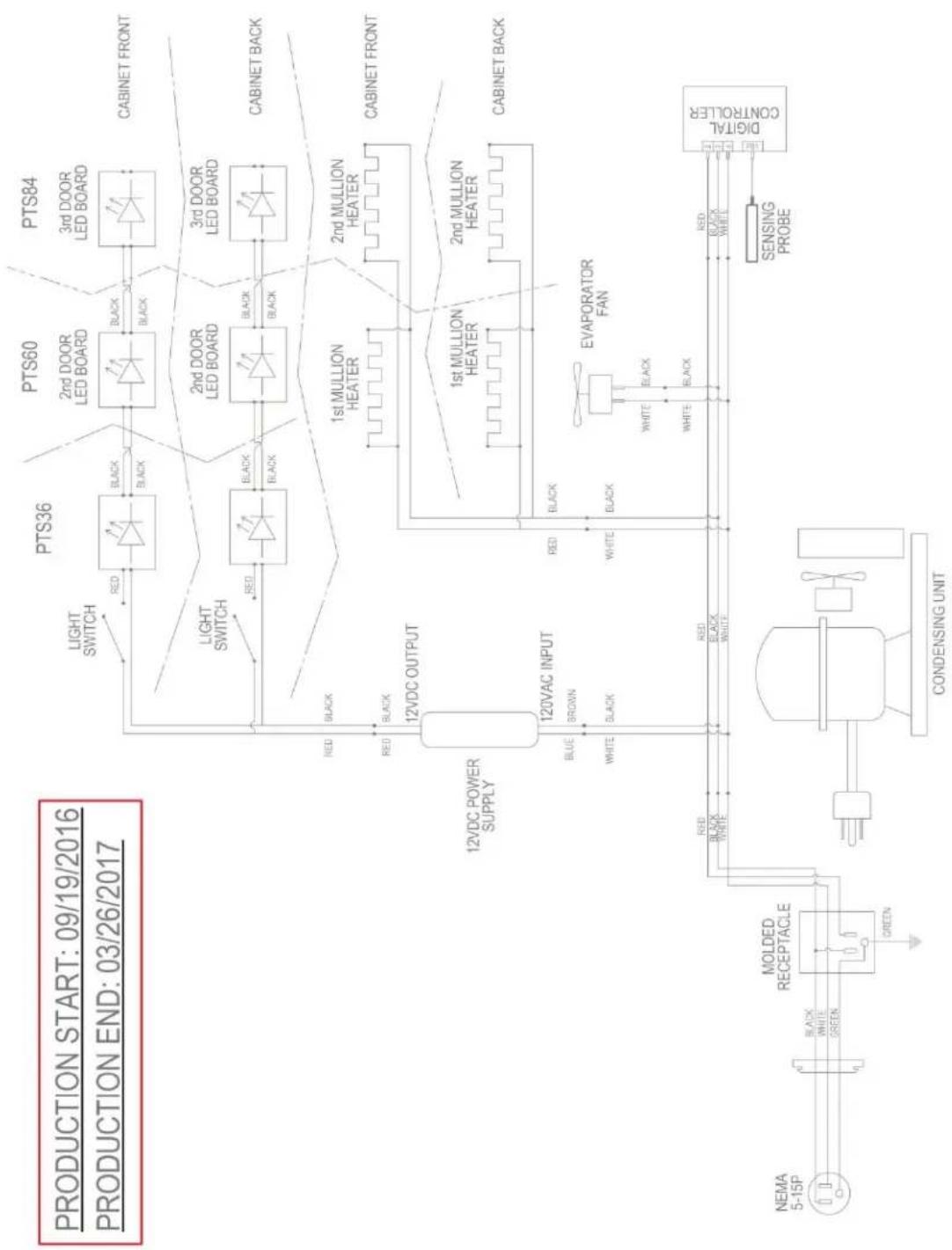
Figure 7-7. PTS36, PTS60, PTS84 Wiring Diagram

flowchart
graph TD
    A["PRODUCTION START: 03/27/2017"] --> B["PRODUCTION END: NA"]
    B --> C["PTS36"]
    B --> D["PTS60"]
    B --> E["PTS84"]
    C --> F["LIGHT SWITCH"]
    D --> G["2nd DOOR LED BOARD"]
    E --> H["3rd DOOR LED BOARD"]
    F --> I["BLACK"]
    G --> J["BLACK"]
    H --> K["BLACK"]
    I --> L["CABINET FRONT"]
    J --> M["CABINET BACK"]
    K --> N["1st MULLION HEATER"]
    L --> O["2nd MULLION HEATER"]
    M --> P["CABINET FRONT"]
    N --> Q["1st MULLION HEATER"]
    O --> R["2nd MULLION HEATER"]
    P --> S["CABINET BACK"]
    T["CONDENSING UNIT PTS60 & PTS84 MODELS"] --> U["INVERTER"]
    U --> V["BLK"]
    V --> W["12VDC POWER SUPPLY"]
    W --> X["12VDC OUTPUT"]
    X --> Y["120VAC INPUT"]
    Y --> Z["BROWN"]
    Z --> AA["BLUE"]
    AA --> AB["WHITE"]
    AB --> AC["BLK"]
    AC --> AD["BLACK"]
    AD --> AE["EVAPORATOR FAN"]
    AE --> AF["DIGITAL CONTROLLER"]
    AG["NEMA 5-15P"] --> AH["MOLDED RECEPTACLE"]
    AH --> AI["GREEN"]
    AJ["CONNECT CONDENSING UNIT HERE"] --> AK["RED BLACK WHITE"]
    AL["MOLDEN"] --> AM["GREEN"]
    AN["SENSING PROBE"] --> AO["Black"]
    AP["CONDENSING UNIT PTS36 ONLY"] --> AQ["RED BLACK WHITE"]
    AR["SENSING PROBE"] --> AS["Black"]
    AT["CONDENSING UNIT PTS60 & PTS84 MODELS"] --> AU["BLK"]
    AV["INVERTER"] --> AW["BLK"]
    AX["12VDC POWER SUPPLY"] --> AY["BROWN"]
    AZ["12VDC OUTPUT"] --> BA["BROWN"]
    BB["SENSING PROBE"] --> BC["Black"]
    BD["SENSING PROBE"] --> BE["Black"]
    BF["SENSING PROBE"] --> BG["Black"]
Figure 7-6. PTS36, PTS60, PTS84 Wiring Diagram

flowchart
graph TD
    A["PRODUCTION START: 09/19/2016"] --> B["PRODUCTION END: NA"]
    B --> C["PTS36"]
    B --> D["PTS60"]
    B --> E["PTS84"]
    C --> F["Light SWITCH"]
    D --> G["2nd DOOR LED BOARD"]
    E --> H["3rd DOOR LED BOARD"]
    F --> I["BLACK"]
    G --> J["BLACK"]
    H --> K["BLACK"]
    I --> L["CABINET FRONT"]
    J --> M["CABINET BACK"]
    K --> N["1st MULLION HEATER"]
    L --> O["2nd MULLION HEATER"]
    M --> P["CABINET FRONT"]
    N --> Q["1st MULLION HEATER"]
    O --> R["2nd MULLION HEATER"]
    P --> S["CABINET BACK"]
    T["12VDC POWER SUPPLY"] --> U["230VAC INPUT"]
    U --> V["Brown"]
    U --> W["Brown"]
    X["GREEN/YELLOW"] --> Y["MOLDED RECEPTACLE"]
    Z[""N" BLUE"] --> AA["BROWN"]
    AB["G"] --> AC["L"]
    AD["G"] --> AE["G"]
    AF[""Orange" BROWN"] --> AG["BROWN UNDER Blue"]
    AH[""Orange" BROWN"] --> AI["BROWN UNDER Orange"]
    AJ["Blue"] --> AK["BROWN"]
    AL["Blue"] --> AM["BROWN"]
    AN["Blue"] --> AO["BROWN"]
    AP["CONDENSING UNIT"] --> AQ["ORANGE BROWN"]
    AR["SENSING PROBE"] --> AS["ORANGE BROWN"]
    AT["EVAPORATOR FAN"] --> AU["WHITE BLACK"]
    AV["Digital CONTROLLER"] --> AW["ORANGE BROWN"]
    AX["Black"] --> AY["BROWN"]
    AZ["Black"] --> BA["BROWN"]
    BB["Black"] --> BC["BROWN"]
Figure 7-6. PTS36, PTS60, PTS84 Wiring Diagram

flowchart
graph TD
    A["Evaporator Fan"] -->|WHITE| B["12VDC POWER SUPPLY"]
    A -->|BLACK| C["EVAPORATOR FAN"]
    D["Evaporator Housing Ground Wire"] -->|GREEN| E["CABINET JUNCTION BOX"]
    D -->|WHITE| F["THES WIRE CAPTED IN SINGLE CABINET INSTALLATIONS"]
    G["PTR48"] --> H["1st DOOR LED BOARD"]
    G --> I["2nd DOOR LED BOARD"]
    G --> J["3rd DOOR LED BOARD"]
    H --> K["Black"]
    I --> L["Black"]
    J --> M["Black"]
    K --> N["Light SWITCH"]
    L --> O["Light SWITCH"]
    M --> P["1st MULLION HEATER"]
    N --> Q["2nd MULLION HEATER"]
    O --> R["1st MULLION HEATER"]
    P --> S["2nd MULLION HEATER"]
    Q --> T["CABINET FRONT"]
    R --> U["CABINET BACK"]
    V["TYPICAL FIELD INSTALLATION"] --> W["POWER CONNECTION"]
    V --> X["PRESSURE SWITCH"]
    V --> Y["CONDENSING UNIT"]
    W --> Z["JUNCTION BOX"]
    X --> AA["NOTE: FIELD WIRING FROM CABINET JUNCTION BOX TO CONDENSING UNIT MUST COMPLY WITH ALL LOCAL AND NATIONAL ELECTRICAL CODES"]
Figure 7-8. PTR48, PTR72 Wiring Diagram

flowchart
graph TD
    A["120VAC INPUT BLUE"] --> B["12VDC POWER SUPPLY"]
    B --> C["12VDC OUTPUT RED BLACK"]
    C --> D["LIGHT SWITCH"]
    D --> E["1st DOOR LED BOARD"]
    E --> F["2nd DOOR LED BOARD"]
    F --> G["3rd DOOR LED BOARD"]
    G --> H["CABINET FRONT"]
    I["EVAPORATOR FAN"] --> J["BLACK RED"]
    K["EVAPORATOR FAN"] --> L["BLACK RED"]
    M["EVAPORATOR"] --> N["BLACK RED"]
    O["EVAPORATOR"] --> P["BLACK RED"]
    Q["EVAPORATOR"] --> R["BLACK RED"]
    S["EVAPORATOR"] --> T["BLACK RED"]
    U["EVAPORATOR"] --> V["BLACK RED"]
    W["EVAPORATOR"] --> X["BLACK RED"]
    Y["EVAPORATOR"] --> Z["BLACK RED"]
    AA["EVAPORATOR"] --> AB["BLACK RED"]
    AC["EVAPORATOR"] --> AD["BLACK RED"]
    AE["EVAPORATOR"] --> AF["BLACK RED"]
    AG["EVAPORATOR"] --> AH["BLACK RED"]
    AI["EVAPORATOR"] --> AJ["BLACK RED"]
    AK["EVAPORATOR"] --> AL["BLACK RED"]
    AM["EVAPORATOR"] --> AN["BLACK RED"]
    AO["TYPICAL FIELD INSTALLATION"] --> AP["POWER CONNECTION"]
    AP --> AQ["PRESSURE SWITCH"]
    AQ --> AR["CONDENSING UNIT"]
    AR --> AS["JUNCTION BOX"]
    AS --> AT["THeses WIRES CAPPED IN SINGLE CABINET INSTALLATIONS"]
    AU["NOTE: FIELD WIRING FROM CABINET JUNCTION BOX TO CONDENSING UNIT MUST COMPLY WITH ALL LOCAL AND NATIONAL ELECTRICAL CODES"] --> AV
    AW["PRODUCTION START: 03/27/2017"] --> AX
    AY["PRODUCTION END: NA"] --> AZ
    style A fill:#f9f,stroke:#333
    style B fill:#ccf,stroke:#333
    style C fill:#cfc,stroke:#333
    style D fill:#fcc,stroke:#333
    style E fill:#cff,stroke:#333
    style F fill:#ffc,stroke:#333
    style G fill:#ffc,stroke:#333
    style H fill:#ffc,stroke:#333
    style I fill:#ffc,stroke:#333
    style J fill:#ffc,stroke:#333
    style K fill:#ffc,stroke:#333
    style L fill:#ffc,stroke:#333
    style M fill:#ffc,stroke:#333
    style N fill:#ffc,stroke:#333
    style O fill:#ffc,stroke:#333
    style P fill:#ffc,stroke:#333
    style Q fill:#ffc,stroke:#333
    style R fill:#ffc,stroke:#333
    style S fill:#ffc,stroke:#333
    style T fill:#ffc,stroke:#333
    style U fill:#ffc,stroke:#333
    style V fill:#ffc,stroke:#333
    style W fill:#ffc,stroke:#333
    style X fill:#ffc,stroke:#333
    style Y fill:#ffc,stroke:#333
    style Z fill:#ffc,stroke:#333
Figure 7-8. PTR48, PTR72 Wiring Diagram


flowchart
graph TD
    A["NEMA 5-15P"] --> B["MOLDED RECEPTACLE"]
    B --> C["CONDENSING UNIT"]
    C --> D["SENSING PROBE"]
    D --> E["Digital CONTROLLER"]
    E --> F["PLUGGED"]
    F --> G["EVAPORATOR FAN"]
    G --> H["Black"]
    H --> I["White"]
    I --> J["Black"]
    J --> K["White"]
    K --> L["Black"]
    L --> M["Red"]
    M --> N["Black"]
    N --> O["White"]
    O --> P["Red"]
    P --> Q["Black"]
    Q --> R["White"]
    R --> S["Red"]
    S --> T["Black"]
    T --> U["White"]
    U --> V["Red"]
    V --> W["Black"]
    W --> X["White"]
    X --> Y["Red"]
    Y --> Z["Black"]
    Z --> AA["White"]
    AA --> AB["Red"]
    AB --> AC["Black"]
    AC --> AD["White"]
    AD --> AE["Red"]
    AE --> AF["Black"]
    AF --> AG["White"]
    AG --> AH["Red"]
    AH --> AI["Black"]
    AI --> AJ["White"]
    AJ --> AK["Red"]
    AK --> AL["Black"]
    AL --> AM["White"]
    AM --> AN["Red"]
    AN --> AO["Black"]
    AO --> AP["White"]
    AP --> AQ["Red"]
    AQ --> AR["Black"]
PRODUCTION START: 3/27/2017
PRODUCTION END: N/A

flowchart
graph TD
    A["NEMA 5-15P"] --> B["MOLDED RECEPTACLE"]
    B --> C["PLUGGED"]
    C --> D["EVAPORATOR FAN"]
    D --> E["RED"]
    E --> F["DIGITAL CONTROLLER"]
    F --> G["SENSING PROBE"]
    B --> H["CONNECT CONDENSING UNIT HERE"]
    H --> I["INVERTER"]
    I --> J["CONDENSING UNIT DDS60, DDS84, DDS106, SSC68, DDC92"]
    B --> K["CONNECT CONDENSING UNIT HERE"]
    K --> L["CONNECT CONDENSING UNIT HERE"]
    L --> M["CONNECT CONDENSING UNIT DDS36 ONLY"]
PRODUCTION START: 09/19/2016
PRODUCTION END: N/A

flowchart
graph TD
    A[""G" GREEN/YELLOW"] --> B[""N" BLUE"]
    B --> C[""L" BROWN"]
    C --> D["MOLDED RECEPTACLE"]
    D --> E["GREEN/YELLOW"]
    E --> F["CONDENSING UNIT"]
    F --> G["BLUE ORANGE BROWN"]
    G --> H["PLUGGED"]
    H --> I["EVAPORATOR FAN"]
    I --> J["WHITE BLACK BLU"]
    J --> K["ORANGE BROWN BLUE"]
    K --> L["DIGITAL CONTROLLER"]
    L --> M["SENSING PROBE"]
    M --> N["Ground"]
7.3 Load Operation Modes
Table 7-2. Load Operation Modes
| LOAD COOLING MODE OFF MODE | DEFROST MODE | ||
| Compressor Energized De | Energized De-Energized | ||
| Condenser Fan Energized | De-Energized De-Energized | ||
| Evaporator Fan Energized | Energized Energized | ||
| Mullion Heaters | Energized Energized | Energized | |
| Eliwell Controller Display |  | No icon illuminated |  |
| Dixell Controller Display |  | No icon illuminated |  |
| Inverter (if applicable) | Energized | De-Energized | De-Energized |
7.4 Electronic Controller
Note: The digital readout is monitoring true air temperature, not product temperature.
Table 7-3. Controller Where-Used Table
| Controller Type | Build Date |
| Eliwell | Beginning 9/19/2016 |
| Dixell | 4/1/2013 to 9/16/2016 |
Eliwell Controller

Press and release controller set key to display 'Machine Status' menu and 'SEt' label.
Press and release the set key again to display the current set point.
Refer to Table 7-4 for factory set point.
To adjust controller set point, press up and down arrow keys within 15 seconds.
Press set key once for controller to memorize new set point.
Be sure to allow 24 hours between temperature controller adjustments.
Dixell Controller

To view set point, press and release SET key.
Refer to Table 7-4 for factory set point.
To change set point value, press and hold SET key for at least 2 seconds. The set point value will be displayed along with a blinking "°C" or "°F" LED.
Release the SET key and then use up or down arrows within 10 seconds to change the set point.
The new set point will be memorized by either pressing SET key again or by waiting 10 seconds.
7.5 Factory Set Point
Table 7-4. Factory Temperature Settings
| Model | Refrigerator °F (°C) | White Wine °F (°C) | Red Wine°F (°C) |
| BBS, BBSN PTS, DZS SDBS, SDPS BBSLP, DDC DDS | 36 (2.2) | 45 (7.2) | 60 (15.5) |
7.5.1 Dixell Controller: Reset Factory Parameter Settings
- Contact Perlick.
7.5.2 Eliwell Controller: Reset Factory Parameter Settings
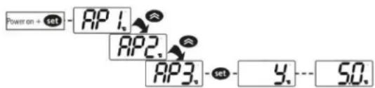
LOADING DEFAULT APPLICATIONS
The procedure used to load one of the default applications is:
- When the instrument switches on, press and hold the lock the label AP1 will appear;
- Scroll though the various applications (AP1-AP2-AP3) using the kAs;
- Select the desired application using the key (AP3 in the example) or cancel the procedure by pressing the key or alternatively wait for the timeout;
- If the operation is successful, the display will show y, otherwise n will appear;
- After a few seconds the instrument will return to the main display.
LOADING APPLICATIONS WHEN EXITING STAND-BY MODE
The procedure for loading one of the preset applications when exiting stand-by mode is:
- Set the instrument in stand-by mode by pressing the Ⓞ button for time H02;
- Exit stand-by mode by pressing the button for time H02;
- Within 10 seconds of exiting stand-by mode, press the button for time H02: AP1 label will appear;
- Scroll through the various applications (AP1-AP2-AP3) using the 🔊 keys;
- Select the desired application using the set key (AP3 in the example) or cancel the procedure by pressing the ① key or alternatively wait for the timeout;
- If the operation is successful, the display will show y, otherwise n will appear;
- After a few seconds the instrument will return to the main display.
| Single Zone Models | Dual Zone Models: Zone 1 Control | Dual Zone Models: Zone 2 Control |
| AP1 = Refrigerator settings (36°F) | AP1 = Refrigerator settings (36°F) | AP1 = Not Used |
| AP2 = White Wine settings (45°F) | AP2 = White Wine settings (45°F) | AP2 = White Wine settings (45°F) |
| AP3 = Red Wine settings (60°F) | AP3 = Not Used | AP3 = Red Wine settings (60°F) |
flowchart
graph LR
    A["Power on + set"] --> B["AP1"]
    B --> C["AP2"]
    C --> D["AP3"]
    D --> E["y"]
    E --> F["50."]
7.5.3 Replacing Control Module
7.5.3.1 Removing Dixell Controller

STEP 1.
Remove the grille by removing 3 Phillips head screws, one at the top center and two at the bottom edge.
STEP 2.
Remove 2 screws holding control cradle to unit.

natural_image
Hand holding a golden object into a black appliance with wires and a microwave oven in the background (no visible text or symbols)STEP 3.
Remove clips holding the controller to the cradle. Control cradle will slide freely from the controller.
CAUTION
Do not attempt to reuse the old wiring harness.

natural_image
Close-up of hands installing or adjusting a device into a plastic enclosure with visible wiring and a green component (no text or symbols)STEP 4.
Cut 2 zip ties holding wire harness to top of the refrigeration module.

natural_image
Close-up of hands connecting electrical cables to a device (no visible text or symbols)STEP 5.
Disconnect evaporator fan wire leads from the main wiring harness.
natural_image
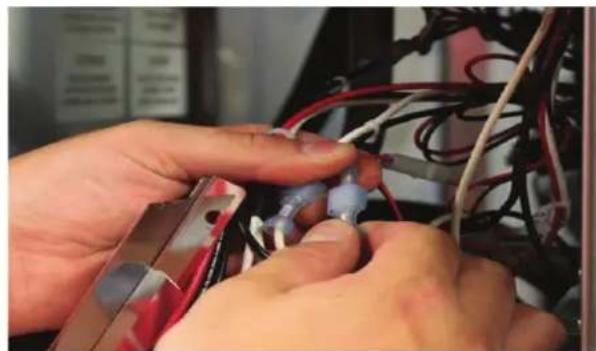
Close-up of hands installing or adjusting cable wiring on a device (no visible text or symbols)STEP 6.
Disconnect mullion heater wire leads from the main wiring harness.

natural_image
Close-up of hands connecting wires to a device (no visible text or symbols)STEP 7.
Disconnect DC driver leads from the main wiring harness.

natural_image
Close-up of hands holding a connector with wires and connectors, no visible text or symbolsSTEP 8.
Remove main wiring harness by disconnecting Molex connector from molded receptacle.

natural_image
Close-up of a hand holding a black connector with wires and wires, connected to a black electrical component (no text or symbols visible)STEP 9.
Remove green probe connector from controller.

natural_image
Close-up of hands installing a component into an electronic device with visible wiring and a green connector (no text or symbols)STEP 10
Remove controller assembly from the unit.
STEP 11.
Remove shelving and pilaster from the unit wall.
STEP 12.
Remove evaporator fan panel. See Figure 6-8.
STEP 13.
Remove screw holding probe bracket to the unit.

natural_image
Close-up of a hand using a yellow screwdriver to test electrical components on a metal panel (no visible text or symbols)STEP 14.
Remove screw holding probe "mass" to the probe bracket and remove the probe.

natural_image
Close-up of hands using a screwdriver to adjust a small electronic component (no visible text or symbols)STEP 15.
Remove sealing compound from top of wire pass-through (inside evaporator box).
STEP 16.
Remove sealing compound from bottom of wire pass-through (inside condenser compartment).
STEP 17.
Pull probe out through the bottom of the evaporator box.
STEP 18.
Discard Dixell probe assembly.
7.5.3.2 Installing Eliwell Controller
Tools required

STEP 1.
Feed Eliwell probe through the bottom of the evaporator box.
STEP 2.
Attach probe and mass onto probe bracket with screw.
STEP 3.
Use pliers if needed to secure probe notch to sheet metal probe bracket. See Figure 7-2.
Crimp gently to avoid damaging the probe. The notch in the probe body should fit into the bracket slot to encapsulate the probe into stainless steel sleeve.

natural_image
Close-up of a hand using a pliers to cut metal components on a wooden surface (no text or symbols visible)Figure 7-11. Attach Probe to Bracket
STEP 4.
Attach the bracket/probe assembly to the bottom of the evaporator box with screw.
STEP 5.
Replace sealing compound at top of wire pass-through (inside evaporator box). Verify a complete seal around the wire harness and pass-through hole.
STEP 6.
Replace the evaporator fan panel.
STEP 7.
Replace the sealing compound at bottom of wire pass-through (inside condenser compartment). Verify a complete seal around the wire harness and pass-through hole.
STEP 8.
Reverse this instruction to connect the replacement wire harness/controller/bracket assembly.
7.5.4 Temperature Probe
Each refrigerated zone has one 10K ohm NTC probe, which senses compartment temperature. Sensing probe is located behind evaporator fan panel.
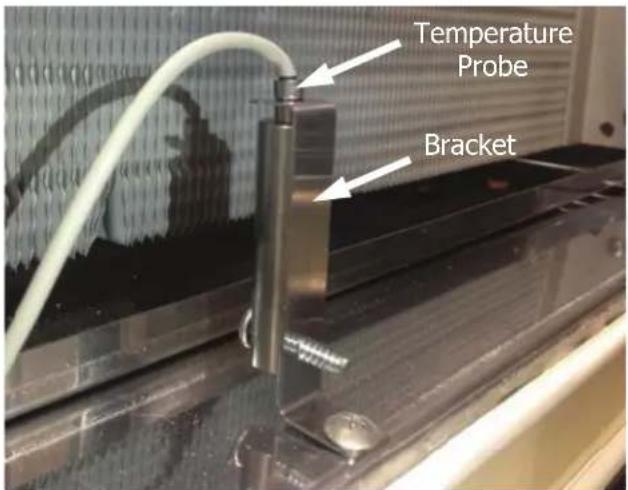
Figure 7-12. Temperature Probe and Bracket
• See Table 7-5 for temperature to resistance values when troubleshooting probe or temperature issues.
Table 7-5. Temperature – Resistance Values
| TEMPERATURE(°C) | TEMPERATURE(°F) | RESISTANCE(OHMS) |
| -30 -22 11 | 1300 | |
| -25 -13 86 | 430 | |
| -20 -4 677 | 70 | |
| -15 5 | 53410 | |
| -10 | 14 | 42470 |
| -5 | 23 | 33900 |
| 0 | 32 | 27280 |
| 5 | 41 | 22050 |
| 10 | 50 | 17960 |
| 15 | 59 | 14690 |
| 20 | 68 | 12090 |
| 25 | 77 | 10000 |
| 30 | 86 | 8313 |
| 35 | 95 | 6940 |
| 40 104 58 | 27 |
| TEMPERATURE(°C) | TEMPERATURE(°F) | RESISTANCE(OHMS) |
| 45 113 4911 | ||
| 50 122 4160 | ||
| 55 131 3536 |
To replace temperature probe, refer to section 7.5.3.
7.6 LED Lighting
7.6.1 Replace LED Light Strip
▲ DANGER
ELECTROCUTION HAZARD!! Never attempt to repair or perform maintenance on unit until main electrical power to the unit has been disconnected!

STEP 1.
Open door or remove upper drawer. See Figure 8-13.
STEP 2.
Using a flat blade screwdriver, carefully pry off the lens cover. See Figure 7-4.
STEP 3.
Remove two screws securing LED light to housing.
STEP 4.
Unplug the LED from the wiring harness.
STEP 5.
Plug new LED into harness and secure to housing using screws removed in step 2.
STEP 6.
Snap LED cover into place.

Figure 7-13. Interior LED Light
7.7 Replace DC Driver/Inverter
STEP 1.
Locate DC Driver/Inverter on ceiling of refrigeration compartment.

STEP 2.
Check voltage.
If not within range printed on the part, replace the part.
STEP 3.
Disconnect DC driver leads from the main wiring harness.

STEP 4.
Use reverse procedure to install replacement DC driver/Inverter.
8.0 Service Instructions - Doors, Drawers, and Shelving
8.1 Proper Door and Drawer Usage
Note: Improper use of doors and drawers can allow extra heat into unit causing extended compressor run times.
- Ensure door or drawers are closed completely and are not left open for a long duration of time. The door can bounce back open slightly and appear closed.
- Ensure the unit is level.
- Ensure doors and drawers are sealing properly when closed.
- No door adjustments should be necessary unless there is major structural damage to cabinet.
8.2 Reverse Door Swing
Note: Changing door swing direction is not advisable if door is not equipped with full length handle. Doing so may result in an undesirable handle position.
Table 8-1. Door Hinges
| HINGE KIT - PART NUMBER DESCRIPTION | |
| 67439R Right Hinging | |
| 67439L Left Hinging | |

STEP 1.
Support the door in the open position as shown in Figure 8-1. Remove the hinge pin.

Figure 8-1. Door Removal
STEP 2.
Pull door to the side and then lower the door.
STEP 3.
Remove top and bottom hinge brackets. Retain screws for later use. See Figure 8-2.

Figure 8-2. Hinge Removal
STEP 4.
Remove hole plugs from top and bottom hinge bracket mounting holes. See Figure 8-2.
Place plugs in holes on opposite side made vacant by removing hinges in step 3.
STEP 5.
Using screws removed in step 3, install top and bottom hinge brackets from kit. See Figure 8-3.

Figure 8-3. Hinge Installation
STEP 6.
Remove top and bottom hinge brackets from door (Figure 8-4). Retain screws for later use.

Figure 8-4. Door Brackets
STEP 7.
Remove front panel from door assembly by removing inner mounting screws (4 per side) from perimeter of door assembly. See Figure 8-5.
Rotate front panel 180° top to bottom. Reattach using same screw and mounting holes.
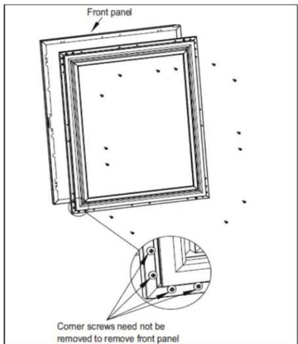
Figure 8-5. Removing Front Panel
STEP 8.
Insert bearing into door top hinge bracket. See Figure 8-6.
STEP 9.
Insert V-block into door bottom hinge bracket and attach with e-clip. See Figure 8-6. Note the orientation of V-block.
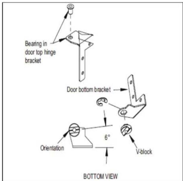
Figure 8-6. Bearing and V-Block
STEP 10.
Attach top and bottom door hinges using screws removed in STEP 6. See Figure 8-7.

Figure 8-7. Door Hinges
STEP 11.
Place lower V-block into lower cabinet hinge with notch parallel to cabinet. See Figure 8-8.

Figure 8-8. Installing V-Block
STEP 12.
Lift door assembly and insert top pin into bearing. Move door toward cabinet and align V-blocks. See Figure 8-8 and Figure 8-9.

Figure 8-9. Installing Door
STEP 13.
Insert and tighten lower hinge pin to complete assembly.
8.3 Replace Door Hinge
See Section 8.2 for hinge replacement instructions.
8.4 Sliding Door Models
8.4.1 Removing/Installing Sliding Doors
STEP 1.
To remove sliding door, simply grasp door on each side and lift up off bottom track, then tilt outwards and pull down to remove from upper track.
STEP 2.
To reinstall sliding door, place door in upper track. Be sure to engage bracket. See Figure 8-10.
Lift door up into track and place into bottom track.

natural_image
Industrial steel structure with a white arrow pointing to a joint detail (no text or symbols visible)Figure 8-10. Removing/Installing Sliding Door
8.4.2 Adjusting Door Spring Tension

Tension spring is in upper track of each door.

Figure 8-11. Door Track
To increase or decrease spring tension:
- Remove Phillips screw
• Position bracket in one of three detents - Reinstall screw
Detent farthest from left provides the least amount of tension.
Units are shipped from factory with springs set at the weakest setting.
8.4.3 Torpedo Spring Adjustment

STEP 1.
Remove doors.
STEP 2.
Remove screw.
STEP 3.
Pull up spring and attached black tab.
STEP 4.
Feed into next notch to tighten/loosen.
STEP 5.
Tighten screw.
8.5 Drawer & Shelf Slides
8.5.1 Shelving Adjustment
CAUTION
Completely empty shelf or drawer before removing.
STEP 1.
Open door and slide shelf out.
STEP 2.
Press locking mechanism. Tilt shelf and remove from unit

natural_image
Close-up of a mechanical component with a metallic handle and circular component, no visible text or symbolsFigure 8-12. Shelf Locking Mechanism
STEP 3.
Reposition each bracket separately. Grasp middle of bracket, pull front end up and out, then forward to remove.
STEP 4.
Place brackets at desired location and reinstall shelf(s).
8.5.2 Drawer Divider Adjustment
▲CAUTION
Completely empty shelf or drawer before removing.
STEP 1.
Lift divider straight up and move to desired position, engaging tabs in holes. Make sure divider tabs engage corresponding holes on both sides.
8.5.3 Cleaning/Lubricating Drawer Extenders
CAUTION
Completely empty shelf or drawer before removing.
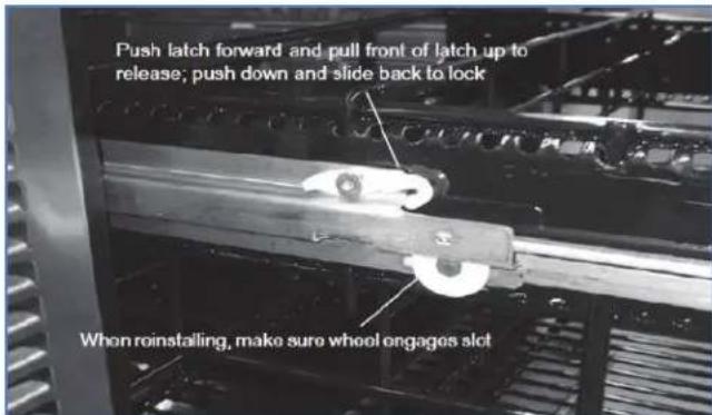
Figure 8-13. Removing/Installing Drawer
STEP 1.
Drawer must be removed to clean or lubricate the extenders.
STEP 2.
Pull the drawer out to its furthest position. Locate the latch in the middle of both extenders. Push each latch forward and lift front of latch up (unlocked position), then lift the front of the drawer and pull out.
STEP 3.
Use a food grade lubricant to lubricate the drawer extenders.
STEP 4.
Place drawer on to the extenders, making sure wheels engage the slots on each side.
STEP 5.
Push drawer all the way in, then pull drawer out and push the latch down and back to engage. Make sure front of latches are fully down and back, engaging the extenders.
8.6 Replace Door & Drawer Gasket
STEP 1.
Remove gasket by lifting at one corner and pulling gasket away from door. Work around the door until gasket is free.
STEP 2.
To replace, start at one corner and press firmly to seat the gasket dart in the channel of the door frame. Listen/feel for a click to indicate the dart is completely seated.
STEP 3.
Finish by going around the gasket once more to feel for any gaps and to ensure the gasket is flat and fully seated.
8.7 Replace Door Handle

STEP 1.
Remove door gasket. See Section 8.6.
STEP 2.
Remove 16 screws underneath door gasket that hold door overlay panel to door frame.
STEP 3.
Remove 3 screws from each door hinge where it is attached to door frame.
STEP 4.
Separate door overlay panel from door frame.
STEP 5.
Door handle can now be removed, 4 X 3/8" hex head bolts.
STEP 6.
Reverse these steps to replace door hinges, overlay panel, and gasket.
8.8 Locks
Gain access to back side of the lock by following directions to remove door handle, Section 8.7.
Note position of door lock strike and reassemble in the same orientation.
8.9 Custom Overlay Panels

Remove front panel from door assembly by removing inner mounting screws (4 per side) from perimeter of door assembly. See Figure 8-14.
Reattach custom overlay panel using same screw and mounting holes.

Figure 8-14. Custom Panel
9.0 Replacement Parts
For parts ordering call (844) 411-8050.
9.1 Refrigeration Module (BBS, BBSN, PTS, SDBS, SDPS, DDS, DDC Model Series)

| BBS, BBSN, PTS, SDBS, SDPS, DDS, DDC MODELS | ||||
| ITEM NUMBER | DESCRIPTION | 1-DOOR QTY. | 2-DOOR QTY. | 3&4-DOOR QTY. |
| 01 Condensing Unit, 1/5 H.P. 115V, BOM #515301064 1 - - | ||||
| 01 Condensing Unit, 1/4 H.P., 115V, BOM #515301063 - 1 - | ||||
| 01 Condensing Unit, 1/3 H.P. 115V, BOM #515301062 - - 1 | ||||
| 02 Screw, Phillips Truss Head Machine 1 1 - | ||||
| 03 Screw, Thread Cutter, Hex Washer Head | 4 | 4 | 4 | |
| 04 Screw, Phillips Truss Head Sheet Metal | 2 2 2 | |||
| 05 Screw, Phillips Pan Head Sheet Metal | 1 1 1 | |||
| 06 Screw, Phillips Head | 9 9 4 | |||
| 07 Screw, Sheet Metal | 20 | 20 | 20 | |
| 08 Screw | 2 2 2 | |||
| 09 Rivet, Pop | 20 | 20 | 20 | |
| 10 Rivnut, Insert | 1 1 - | |||
| 11 Low Side Foamed Assembly | 1 1 1 | |||
| 12 Gasket, .25" | 2 2 2 | |||
| 13 Probe, Temperature | 1 1 1 | |||
| 14 Foam, Divider | 1 1 1 | |||
| 15 Sleeve, Sensor Insulating | 1 1 1 | |||
| 16 Tube, Drain, Evaporator Pan to Condenser Pan | 1 1 1 | |||
| 17 Bracket, Temperature Sensor | 1 1 1 | |||
| 19 Tube, Evaporator | 1 1 - | |||
| 18 Tube, Crimped Evaporator | 1 1 - | |||
| 20 Bracket, Top Pull Down | 2 2 2 | |||
| 21 Standoff, Grille | 1 1 1 | |||
| 22 LED Driver | 1 1 1 | |||
| 23 Controller | 1 1 1 | |||
| 24 Panel, Outer Side, High Side | 1 1 1 | |||
| 25 Panel, Inner Side, High Side | 1 1 1 | |||
| 26 Base, High Side | 1 1 1 | |||
| 27 Cover, Back, High Side | 1 1 1 | |||
| 28 Rail, Condensate Pan | 2 2 2 | |||
| 29 Pan, Condensate, High Side | 1 1 1 | |||
| 30 Grille, Front | 1 1 1 | |||
| 31 Pan, Evaporator | 1 1 1 | |||
| 32 Evaporator Fin Coil | 1 1 1 | |||
| 33 Baffle, Compressor | 1 1 1 | |||
| 34 Bracket, Compressor | 1 1 1 | |||
| 35 L & S Line, 1 Door | 1 - - | |||
| 35 L & S Line, 2 Door | - 1 - | |||
| 35 L & S Line, 3 & 4 Door - - 1 | ||||
| 36 Power Cord, with Molded Receptacle 1 1 1 | ||||
| 37 Wire Harness, Refrigeration Module 1 1 1 | ||||
| 38 Bracket, Controller Mounting 1 1 1 | ||||
| 39 Screw, Phillips Head 1 1 1 | ||||
| 40 Screw, Phillips Head Machine 1 1 1 | ||||
9.2 Refrigeration Module (BBSLP Model Series)

| BBSLP MODELS | ||||
| ITEM NUMBER | DESCRIPTION | 1-DOOR QTY. | 2-DOOR QTY. | 3&4-DOOR QTY. |
| 01 Condensing Unit, 1/3 HP, 115V - - 1 | ||||
| 01 Condensing Unit, 1/4 HP 115V - 1 - | ||||
| 01 Condensing Unit, 1/5 HP, 115V 1 - - | ||||
| 02 Base, High Side 1 1 1 | ||||
| 03 Bracket, Hold Down, Compressor 1 1 1 | ||||
| 04 Panel, Baffle, Compressor 1 1 1 | ||||
| 05 Rai, Condensate Pan | 2 2 2 | |||
| 06 Panel, Outer Side, High Side | 1 1 1 | |||
| 07 Panel, Inner Side, High Side | 1 1 1 | |||
| 08 Screw, Thread Cutter, 1/4-20 X 5/8 | 4 | 4 | 4 | |
| 09 Par, Condensate | 1 1 1 | |||
| 10 Gasket | 2 2 2 | |||
| 11 Foam Block, Divider Baffle | 1 1 1 | |||
| 12 Low Side Shell Assembly | 1 1 1 | |||
| 13 Par, Evaporator, Assembly | 1 1 1 | |||
| 14 Coil, Evaporator, 5 X 14 X 1.9 | 1 | 1 | 1 | |
| 15 Tube, Drain, To Evaporator Pan 1 1 1 | ||||
| 16 Tube, Outlet, Evaporator | 2 2 2 | |||
| 17 Power Cord with Molded | 1 1 1 | |||
| 18 Screw, Sheet Metal, #10 X 1 1/4 Phillips | 1 | 1 | 1 | |
| 19 Driver, 12 VDC, 60 Watt, Meanwell Lpv-60-12 | 1 | 1 | 1 | |
| 20 Bracket, Temp Sensor | 1 1 1 | |||
| 21 Sleeve, Sensor Insulating | 1 1 1 | |||
| 22 Probe, Temperature, NTC, 10k | 1 1 1 | |||
| 23 Screw, Sheet Metal, #10 X 1", Phillips | 1 | 1 | 1 | |
| 24 Cover, Back, High Side | 1 1 1 | |||
| 25 Standoff, Grille | 1 | 1 | 1 | |
| 26 Screw, Machine, #8-32, 2-1/2" Black Zinc Plated | 1 | |||
| 26 Screw, Machine, #8-32, 2-1/2" Zinc Plated | Customer Option | |||
| 27 Screw, #10 X 1/2" Phillips Truss Head SMS, #410 | 4 | 4 | 4 | |
| 28 Controller Mounting Bracket | 1 1 1 | |||
| 29 Control | 1 1 1 | |||
| 30 Screw, Sheet Metal, #10-16 X 1/2" | 5 | 5 | 5 | |
| 31 Top Pull Down Bracket | 2 2 2 | |||
| 32 Screw, Tri-lobe, 1/4-20x 1/2" Phillips Flat Head | 2 | 2 | 2 | |
| 33 Wire Harness, Condenser Housing | 1 1 1 | |||
| 34 L & S Line, 1 Door, Back Bar | 1 | - | - | |
| 34 L & S Line, 2 Door, Back Bar | - 1 - | |||
| 34 L & | S Line, 3 & 4 Door, Back Bar - - 1 | |||
| 35 Wire Harness, Fan Motors 1 1 1 | ||||
| 36 Harness 12VDC Split Male-Female 1 1 1 | ||||
| 37 Grille, Front, S.S. | 1 | |||
| 37 Grille, Front, Black Vinyl Customer Option | ||||
| 38 Screw, Sheet Metal, #6 X 3/4", Phillips 2 2 2 | ||||
| 39 Cover, Dc Driver, Low Ht. Back Bar 1 1 1 | ||||
9.3 Refrigeration Module (DZS60 Model Series)
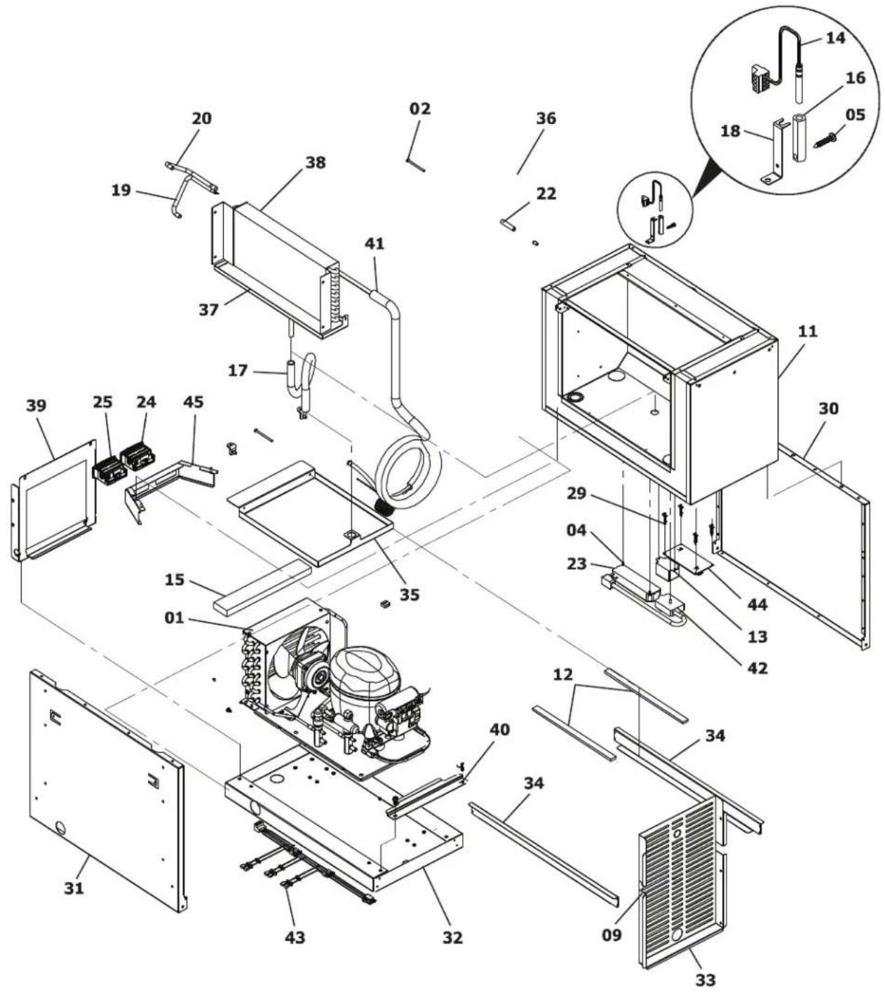
| DZS60 MODELS | ||
| ITEM NUMBER | DESCRIPTION QTY. | |
| 01 Condensing Unit, 1/4 H.P., 115V 1 | ||
| 02 Screw, Machine, #8-32 x 2-1/2" Lg, Phillips Truss Head 1 | ||
| 03 | Screw, Thread Cutter, 1/4-20 x 5/8 Hex Washer Head, Type 23, Steel | 4 |
| 04 | Screw, Sheet Metal, #6 x 1/2", Type "A", PH Truss Head - Full Contoured, 18-8 | 2 |
| 05 | Screw, Sheet Metal, #10 x 1", PH Pan Head, Type "B", Steel, Hardened | 1 |
| 06 Screw, #10 X 1/2" PH Truss Head SMS #410 S.S., Type "AB" 9 | ||
| 07 | Screw, Sheet Metal, #10-16 x 1/2" Hex Flange Grip-Lite, Type "AB" | 20 |
| 08 Screw, Thread Forming, 1/4-20 X 1/2" 2 | ||
| 09 Rivet, Pop 20 | ||
| 10 Rivnut, Insert | 1 | |
| 11 Low Side Foamed Assembly | 1 | |
| 12 Gasket, Foam .25" | 2 | |
| 13 Relay, Pump, 120VAC Rating | 1 | |
| 14 | Probe, Temperature, NTC, 10K Ohm XW60L, 1.8" Nickel Plated | 1 |
| 15 Foam, Divider, 12" | 1 | |
| 16 Sleeve, Sensor Insulating | 1 | |
| 17 Tube, Drain, Evaporator Pan to Condenser Pan | 1 | |
| 18 Bracket, Temperature Sensor, Back Bar | 1 | |
| 19 Tube, IO, Evaporator, Back Bar (Crimped for Cap Tube) 1 | ||
| 20 Tube, IO, Evaporator, Back Bar | 1 | |
| 21 Top Pull Down Bracket, Back Bar | 2 | |
| 22 Standoff, Grille, Back Ba | 1 | |
| 23 LED Driver 1 | ||
| 24 Control | 1 | |
| 25 Red Display | 1 | |
| 26 Harness 12 VDC Split Male-Female | 1 | |
| 27 Harness, Line Voltage Split | 1 | |
| 28 Harness Stepper Controller Input | 1 | |
| 29 Standoff | 4 | |
| 30 Panel, Outer Side, High Side | 1 | |
| 31 Panel, Inner Side, High Side, Back Bar | 1 | |
| 32 Base, High Side | 1 | |
| 33 Cover, Back, High Side | 1 | |
| 34 Rai, Condensate Pan, Back Bar | 2 | |
| 35 Par, Condensate, High Side | 1 | |
| 36 Grille, Front, Back Bar | 1 | |
| 37 Par, Evaporator, Assembly, Back Bar | 1 | |
| 38 Evaporator Fin Coil | 1 | |
| 39 Baffle, Compressor 1 | ||
| 40 Bracket, Compressor 1 | ||
| 41 L & S Line, 2 Door Back Bar 1 | ||
| 42 Power Cord with Molded Receptacle, 14/3, Back Bar 1 | ||
| 43 Wire Harness, Refrigeration Module, Back Bar 1 | ||
| 44 Controller Board-Damper, Dual Zone Commercial 1 | ||
| 45 Controller Mounting Bracket 1 | ||
| 46 Screw, #10 X .500 PH TRUSS HEAD 1 | ||
| 47 Plated Screw, Machine, 8-32,2-1/2" Lg Phillip Truss Head, Steel, Black Zinc 1 | ||
9.4 Refrigeration Module (DZS36 Model Series)

| DZS36 MODELS | ||
| ITEM NUMBER | DESCRIPTION QTY. | |
| 01 Condensing Unit, 1/5 H.P. 115V 1 | ||
| 02 Screw, Machine, #8-32 x 2-1/2” Lg, Phillips Truss Head 1 | ||
| 03 | Screw, Thread Cutter, 1/4-20 x 5/8 Hex Washer Head, Type 23, Steel | 4 |
| 04 | Screw, Sheet Metal, #6 x 1/2", Type "A", PH Truss Head - Full Contoured, 18-8 | 2 |
| 05 | Screw, Sheet Metal, #10 x 1", PH Pan Head, Type "B", Steel, Hardened | 1 |
| 06 Screw, #10 X 1/2" PH Truss Head SMS #410 S.S., Type "AB" 9 | ||
| 07 | Screw, Sheet Metal, #10-16 x 1/2" Hex Flange Grip-Lite, Type "AB" | 20 |
| 08 Screw, Thread Forming, 1/4-20 X 1/2" 2 | ||
| 09 Rivet, Pop, 1/8" Dome Head, S.S., .063" -.125" Grip Range 20 | ||
| 10 Rivnut, Insert, #8-32, Steel, Zinc & Yellow Chromate Plated 1 | ||
| 11 Low Side Foamed Assembly 1 | ||
| 12 Gasket, Low Perm Polyether Foam .25" | 2 | |
| 13 Relay, Pump, 120VAC Rating | 1 | |
| 14 Probe, Temperature, NTC, 10K Ohm XW60L, 1.8" Nickel Plated | 1 | |
| 15 Foam, Divider, 12" | 1 | |
| 16 Sleeve, Sensor Insulating | 1 | |
| 17 Tube, Drain, Evap Pan to Cond Pan | 1 | |
| 18 Bracket, Temperature Sensor, Back Bar | 1 | |
| 19 Tube, IO, Evaporator, Back Bar (Crimped for Cap Tube) | 1 | |
| 20 Tube, IO, Evaporator, Back Bar | 1 | |
| 21 Standoff, Grille, Back Bar | 1 | |
| 22 LED Driver | 1 | |
| 23 Control | 1 | |
| 24 Red Display | 1 | |
| 25 Top Pull Down Bracket, Back Bar | 2 | |
| 26 Harness Stepper Controller Input | 1 | |
| 27 Standoff | 4 | |
| 28 Panel, Outer Side, High Side | 1 | |
| 29 Panel, Inner Side, High Side, Back Bar | 1 | |
| 30 Base, High Side | 1 | |
| 31 Cover, Back, High Side | 1 | |
| 32 Rail, Condensate Pan, Back Bar | 2 | |
| 33 Pan, Condensate, High Side | 1 | |
| 34 Grille, Front, Back Bar | 1 | |
| 35 Pan, Evaporator, Assembly, Back Bar | 1 | |
| 36 Evaporator Fin Coil | 1 | |
| 37 Baffle, Compressor | 1 | |
| 38 Bracket, Compressor | 1 | |
| 39 L & S Line, 1 Door Back Bar | 1 | |
| 40 Power Cord with Molded Receptacle, 14/3, Back Bar | 1 | |
| 41 Wire Harness, Refrigeration Module, Back Bar 1 | ||
| 42 Controller Mounting Bracket 1 | ||
| 43 Controller Board-Damper, Dual Zone Commercial 1 | ||
| 44 Screw, #10 X .500 PH Truss Head 1 | ||
| 45 Screw, Machine, 8-32,2-1/2" Lg Phillip Truss Head, Steel, Black Zinc, Plated 1 | ||
| DDS60-IR, DDS84-IR, DDS108-IR MODELS | |||
| ITEM NUMBER | DESCRIPTION | 2-DOOR QTY. | 3&4- DOOR QTY. |
| 01 Condensing Unit, 1/3 H.P. 115V - 1 | |||
| 01 Condensing Unit, 1/4 H.P., 115V 1 - | |||
| 02 Screw, Machine, 8-32, 2-1/2" Lg Phillip Truss Head, Steel, Black Zinc, Plated 2 2 | |||
| 03 Screw, Thread Cutter, 1/4-20 x 5/8 Hex Washer Head, Type 23, Steel | 4 | 4 | |
| 04 Screw, Sheet Metal, #10 x 1", PH Pan Head, Type "B", Steel, Hardened | 1 | 1 | |
| 05 Screw, #10 X 1/2" PH Truss Head SMS #410 S.S., Type "AB" 15 10 | |||
| 06 Screw, Sheet Metal, #10-16 x 1/2" Hex Flange Grip-Lite, Type "AB" | 14 | 20 | |
| 07 Screw, Thread Forming, 1/4-20 X 1/2" | 2 | 2 | |
| 08 Rivet, Pop, 1/8" Dome Head, S.S., .063" - .125" Grip Range | 26 26 | ||
| 09 Rivnut, Insert, #8-32, Steel, Zinc & Yellow Chromate Plated | 1 1 | ||
| 10 Low Side Foamed Assembly | 1 1 | ||
| 11 Gasket, Low Perm Polyether Foam .25" | 2 2 | ||
| 12 Probe, Temperature, NTC, 10K Ohm XW60L, 1.8" Nickel Plated | 1 | 1 | |
| 13 Foam, Divider, 12" | 1 1 | ||
| 14 Snap Bushing, For 1" Hole, Nylon, Black | 1 1 | ||
| 15 Sleeve, Sensor Insulating | 1 1 | ||
| 16 Tube, Drain, Evaporator Pan to Condenser Pan | 1 1 | ||
| 17 Bracket, Temperature Sensor, Back Bar | 1 1 | ||
| 18 Tube, IO, Evaporator, Back Bar (Crimped for Cap Tube) | 1 | 1 | |
| 19 Tube, IO, Evaporator, Back Bar | 1 1 | ||
| 20 Top Pull Down Bracket, Back Bar | 2 2 | ||
| 21 Standoff, Grille, Back Bar | 1 1 | ||
| 22 Control | 1 1 | ||
| 23 Panel, Outer Side, High Side | 1 1 | ||
| 24 Panel, Inner Side, High Side, Back Bar | 1 1 | ||
| 25 Base, High Side | 1 1 | ||
| 26 Rail, Condensate Pan, Back Bar | 2 2 | ||
| 27 Pan, Condensate, High Side | 1 1 | ||
| 28 Grille, Front, Back Bar | 1 1 | ||
| 29 Pan, Evaporator, Assembly, Back Bar | 1 1 | ||
| 30 Evaporator Fin Coil | 1 1 | ||
| 31 Baffle, Compressor | 1 1 | ||
| 32 Bracket, Compressor | 1 1 | ||
| 33 L & S Line, 2 Door Back Bar | 1 - | ||
| 33 L & S Line, 3 & 4 Door Back Bar | - 1 | ||
| 34 Power Cord with Molded Receptacle, 14/3, Back Bar | 1 1 | ||
| 35 Wire Harness, Refrigeration Module, Back Bar 1 1 | |||
| 36 Controller Mounting Bracket 1 1 | |||
| 37 Panel, Back, Flush, High Side, Back Bar 1 1 | |||
| 38 Bracket, Mounting, Flush Back Panel, Back Bar 2 2 | |||
| 39 Screw, #10 X .500 PH Truss Head 1 1 | |||
9.6 Fan Motor Assembly Parts (Self-Contained Model Series)

| SELF-CONTAINED MODELS | ||
| ITEM NUMBER | DESCRIPTION QTY. | |
| 01 Motor, Fan 1 | ||
| 02 Panel, Fan Mounting 1 | ||
| 03 Panel, Inner Grille 1 | ||
| 04 Screw, Motor Mounting 4 | ||
| 05 Screw, Grille Mounting 8 | ||
| 06 Guard, Product 1 | ||
| 07 Screw, Guard Mounting 2 | ||
9.7 Low Profile Evaporator Parts (BBSLP Model Series)

| LOW PROFILE MODELS | ||
| ITEM NUMBER | DESCRIPTION QTY. | |
| 01 Fan, Evaporator 3 | ||
| 02 Panel, Fan Mounting 1 | ||
| 03 Screw, Fan Mounting 12 | ||
| 04 Grille 1 | ||
| 05 Screw, Grille Mounting 2 | ||
| 06 Handle, Guard 6 | ||
| 07 Screw, Guard Handle Mounting 2 | ||
9.8 Remote Evaporator Parts (BBR, BBRN, PTR, SDBR & BBRLP Model Series)

| REMOTE MODELS | ||
| ITEM NUMBER | DESCRIPTION QTY. | |
| 01 Motor, Fan 1 | ||
| 02 Panel, Fan Mounting 1 | ||
| 01 Bracket, Fan 2 | ||
| 02 Control, Temperature 1 | ||
| 03 Pan, Evaporator 1 | ||
| 04 Bushing, 1.75” I.D. 1 | ||
| 05 Guard, Plastic Fan 2 | ||
| 06 Fan | Panel, Evaporator (Right) 1 | |
| 07 Fan | Panel, Evaporator (Left) 1 | |
| 08 Plug, Dome 1 | ||
| 09 Motor, Fan 2 | ||
| 10 Blade, Fan 2 | ||
| 11 Evaporator Assembly 1 | ||
| Coil, 21" Fin 1 | ||
| Tube, Evaporator Outlet 1 | ||
| Tube, Evaporator Inlet 1 | ||
| Clamp, Control Bulb 1 | ||
| 12 Silicone - | ||
Perlick®
- Commercial Back Bar Refrigeration
- Self-Contained and Remote
- Table of Contents
- GENERAL INFORMATION ...... 1-1
- SAFETY INFORMATION 2-1
- TROUBLESHOOTING GUIDE – REFRIGERATION SYSTEM.... 3-1
- TROUBLESHOOTING GUIDE – ELECTRICAL SYSTEM 4-1
- TROUBLESHOOTING GUIDE – DOORS, DRAWERS AND SHELVING .... 5-1
- REFRIGERATION SYSTEM REPAIR INSTRUCTIONS 6-1
- ELECTRICAL SYSTEM REPAIR INSTRUCTIONS.... 7-1
- SERVICE INSTRUCTIONS - DOORS, DRAWERS, AND SHELVING 8-1
- REPLACEMENT PARTS 9-1
- Table of Figures
- Table of Tables
- General Information
- Use of Service Manual
- Model Families
- Safety Information
- Refrigerant HFC-134a
- Potential Problems with HFC-134a
- Service Manual Safety Labels
- ⚠️ DANGER
- HAZARD!!
- ▲ WARNING
- ▲CAUTION
- CAUTION
- WARNING
- Troubleshooting Guide – Refrigeration System
- Troubleshooting Guide – Electrical System
- DANGER
- Troubleshooting Guide – Doors, Drawers and Shelving
- Refrigeration System Repair Instructions
- Air Infiltration
- STEP 1. Door Gaskets
- STEP 2. Sealing Compound
- STEP 3. Silicone Seal (RTV type)
- STEP 4. Floor Drain
- Slide Out the Refrigeration Deck
- STEP 1.
- STEP 2.
- STEP 3.
- Plumbing for Remote Drain
- System Operating Pressures
- First Time Pull-Down
- Normal Cycling
- Stabilization
- Service Valves
- STEP 3. Recording pressure
- De-Ice Blocked Evaporator Coil – Self-Contained Models
- STEP 4.
- STEP 5. When ice has been removed:
- STEP 6.
- Air Flow Obstructions
- Clean Condenser Coil
- Ambient Temperature
- Compressors and Condensing Unit (units shipped pre 3-27-2017 only)
- Replace Condenser Fan Motor
- STEP 5.
- Replace Evaporator Fan Motor – Self-Contained Models
- STEP 7.
- STEP 8.
- STEP 9.
- STEP 10.
- STEP 11.
- Replace Compressor
- Leak Detection
- Recharge Procedure
- Replace compressor starting device – Self-contained models
- Troubleshooting Guide – Refrigeration System: Variable Speed Compressor\*
- ELECTROCUTION HAZARD!!
- Compressor/Inverter Test Procedures
- Compressor Diagnostic
- Resistance Readings:
- Inverter Diagnostic
- Accessing the Inverter
- Variable Speed Compressor Change
- Compressor Change Procedures:
- Wiring Connections
- Troubleshooting
- (After Compressor Replacement)
- Electrical System Repair Instructions
- Electrical Specifications (units shipped pre 3-27-2017 only)
- Wiring Diagrams
- Load Operation Modes
- Electronic Controller
- Eliwell Controller
- Dixell Controller
- Factory Set Point
- Dixell Controller: Reset Factory Parameter Settings
- Eliwell Controller: Reset Factory Parameter Settings
- LOADING DEFAULT APPLICATIONS
- LOADING APPLICATIONS WHEN EXITING STAND-BY MODE
- Replacing Control Module
- Removing Dixell Controller
- STEP 10
- STEP 12.
- STEP 13.
- STEP 14.
- STEP 15.
- STEP 16.
- STEP 17.
- STEP 18.
- Temperature Probe
- LED Lighting
- Replace LED Light Strip
- ▲ DANGER
- Replace DC Driver/Inverter
- Service Instructions - Doors, Drawers, and Shelving
- Proper Door and Drawer Usage
- Reverse Door Swing
- Replace Door Hinge
- Sliding Door Models
- Removing/Installing Sliding Doors
- Adjusting Door Spring Tension
- Torpedo Spring Adjustment
- Drawer & Shelf Slides
- Shelving Adjustment
- Drawer Divider Adjustment
- Cleaning/Lubricating Drawer Extenders
- Replace Door & Drawer Gasket
- Replace Door Handle
- Locks
- Custom Overlay Panels
- Replacement Parts
- Refrigeration Module (BBS, BBSN, PTS, SDBS, SDPS, DDS, DDC Model Series)
- Low Profile Evaporator Parts (BBSLP Model Series)
- Perlick®
Brand : Perlick
Model : DDS108
Category : Beer dispenser