
Smarty Max - Machine à effets Elation - Free user manual and instructions
Find the device manual for free Smarty Max Elation in PDF.


| Product Type | Fog Machine |
| Brand | Elation |
| Model | Smarty Max |
| Dimensions (L x W x H) | 15 x 10 x 8 inches (approx.) |
| Weight | 12 lbs (approx.) |
| Power Supply | AC 120V / 60Hz (or 230V / 50Hz depending on region) |
| Power Consumption | 1000W |
| Fluid Capacity | 1 liter tank |
| Heating Time | Approximately 2-3 minutes |
| Output | Adjustable fog output with remote control |
| Remote Control | Wired remote included |
| DMX Support | DMX512 via 3-pin XLR |
| Control Modes | Manual, remote, DMX |
| Safety Features | Automatic shut-off when fluid low; thermal cutout |
| Cleaning | Use distilled water or cleaning solution after every 20 hours of use |
| Spare Parts | Heater, pump, fuse, remote control available |
| Repairability | User-replaceable fuses; professional service recommended for heater/pump |
| Warranty | 1 year limited warranty |
Frequently Asked Questions - Smarty Max Elation
User questions about Smarty Max Elation
0 question about this device. Answer the ones you know or ask your own.
Ask a new question about this device
Download the instructions for your Machine à effets in PDF format for free! Find your manual Smarty Max - Elation and take your electronic device back in hand. On this page are published all the documents necessary for the use of your device. Smarty Max by Elation.
USER MANUAL Smarty Max Elation
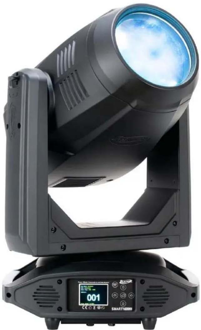
natural_image
Exterior view of a black triangular light fixture with a digital display showing '001' and 'SMART16000' (no readable text or symbols on the device itself)SMARTYMAX™
user manual
©2023 ELATION PROFESSIONAL all rights reserved. Information, specifications, diagrams, images, and instructions herein are subject to change without notice. ELATION PROFESSIONAL logo and identifying product names and numbers herein are trademarks of ELATION PROFESSIONAL. Copyright protection claimed includes all forms and matters of copyrightable materials and information now allowed by statutory or judicial law or hereinafter granted. Product names used in this document may be trademarks or registered trademarks of their respective companies and are hereby acknowledged. All non-ELATION brands and product names are trademarks or registered trademarks of their respective companies.
ELATION PROFESSIONAL and all affiliated companies hereby disclaim all liabilities for property, equipment, building, and electrical damages, injuries to any persons, and direct or indirect economic loss associated with the use or reliance of any information contained within this document, and/or because of the improper, unsafe, insufficient, and negligent assembly, installation, rigging, and operation of this product.
Elation Professional USA | 6122 S. Eastern Ave. | Los Angeles, CA. 90040 323-582-3322 | 323-832-9142 fax | www.elationlighting.com | info@elationlighting.com
Elation Professional B.V. I Junostraat 2 I 6468 EW Kerkrade, The Netherlands +31 45 546 85 66 I +31 45 546 85 96 fax I www.elationlighting.eu I info@elationlighting.eu
Elation Professional Mexico I AV Santa Ana 30 I Parque Industrial Lerma, Lerma, Mexico 52000 +52 (728) 282-7070
DOCUMENT VERSION

Due to additional product features and/or enhancements, an updated version of this document may be available online. Please scan the QR Code with your mobile device or visit www.elationlighting.com for the latest revision/update of this manual before installation and/or programming.
| Date | Document Version | Software Version ≥ | DMX Channel Modes | Notes |
| 09/17/19 | 1.0 | 1.3.1 | 27 / 44 | Initial release. |
| 08/17/20 | 1.2 | N/C | NO CHANGE | Updated thermal |
| 10/06/20 | 1.4 | N/C | NO CHANGE | Updated specifications |
| 01/11/21 | 1.6 | 1.3.4 | NO CHANGE | Updated sun protection |
| 07/22/21 | 1.8 | 1.3.5 | NO CHANGE | Added FIL dimensions, updated Software version to 1.3.5 to add Primary/Secondary |
| 11/15/22 | 2.0 | 1.5 | NO CHANGE | Updated System Menu, DMX Traits, and Truss Clamp information |
| 03/07/23 | 2.1 | 2.01 | No Change | Updated System Menu, DMX Traits, Fixture Transport and Handling |
| 08/24/23 | 2.2 | N/C | No Change | Removed Fixture Transport and Handling; updated Dimensional Drawings, Software Updates, Optional Accessories |
CONTENTS
General Information 4
Limited Warranty (USA Only) 5
Safety Guidelines 6
Discharge Lamp Warning 8
Maintenance Guidelines 9
Fixture Overview 10
Colors, Gobos, Animation 11
Gobo Size 12
Gobo Replacement 13
Lamp Replacement 17
Fixture Installation 22
Sun Protection Mode | Hibernation Mode 26
System Menu 27
Dimmer Mode 35
DMX Traits: Channel Functions and Values 36
Remote Device Management (RDM) 43
Software Updates 44
Error Codes 45
Specifications 46
Dimensional Drawings 47
Optional Accessories 49
FCC Statement 50
GENERAL INFORMATION
INTRODUCTION
Please read and understand the instructions in this manual carefully and thoroughly before attempting to operate this device. These instructions contain important safety and use information.
This device is intended for use by professionally trained personnel only, and so is not suitable for private use.
UNPACKING
Every device has been thoroughly tested and has been shipped in perfect operating condition. Carefully check the shipping carton for damage that may have occurred during shipping. If the carton is damaged, carefully inspect the device for damage, and be sure all accessories necessary to install and operate the device have arrived intact. In the event damage has been found or parts are missing, please contact our customer support team for further instructions. Please do not return this device to your dealer without first contacting customer support. Please do not discard the shipping carton in the trash. Please recycle whenever possible.
BOX CONTENTS
Omega Brackets (x2)
IP65 Power Cable
CUSTOMER SUPPORT
Contact ELATION Service for any product related service and support needs. Also visit forums.elationlighting.com with questions, comments or suggestions.
ELATION SERVICE USA - Monday - Friday 8:00am to 4:30pm PST 323-582-3322 | Fax 323-832-9142 | support@elationlighting.com
ELATION SERVICE EUROPE - Monday - Friday 08:30 to 17:00 CET +31 45 546 85 63 | Fax +31 45 546 85 96 | support@elationlighting.eu
REPLACEMENT PARTS please visit parts.elationlighting.com
LIMITED WARRANTY (USA ONLY)
A. Elation Professional hereby warrants, to the original purchaser, Elation Professional products to be free of manufacturing defects in material and workmanship for a period of two years (730 days), and Elation Professional product rechargeable batteries to be free of manufacturing defects in material and workmanship for a period of six months (180 days), from the original date of purchase. This warranty excludes discharge lamps and all product accessories. This warranty shall be valid only if the product is purchased within the United States of America, including possessions and territories. It is the owner's responsibility to establish the date and place of purchase by acceptable evidence, at the time service is sought.
B. For warranty service, send the product only to the Elation Professional factory. All shipping charges must be pre-paid. If the requested repairs or service (including parts replacement) are within the terms of this warranty, Elation Professional will pay return shipping charges only to a designated point within the United States. If any product is sent, it must be shipped in its original package and packaging material. No accessories should be shipped with the product. If any accessories are shipped with the product, Elation Professional shall have no liability what-so-ever for loss and/or or damage to any such accessories, nor for the safe return thereof.
C. This warranty is void if the product serial number and/or labels are altered or removed; if the product is modified in any manner which Elation Professional concludes, after inspection, affects the reliability of the product; if the product has been repaired or serviced by anyone other than the Elation Professional factory unless prior written authorization was issued to purchaser by Elation Professional; if the product is damaged because not properly maintained as set forth in the product instructions, guidelines and/or user manual.
D. This is not a service contract, and this warranty does not include any maintenance, cleaning or periodic check-up. During the periods as specified above, Elation Professional will replace defective parts at its expense, and will absorb all expenses for warranty service and repair labor by reason of defects in material or workmanship. The sole responsibility of Elation Professional under this warranty shall be limited to the repair of the product, or replacement thereof, including parts, at the sole discretion of Elation Professional. All products covered by this warranty were manufactured after January 1, 1990, and bare identifying marks to that effect.
E. Elation Professional reserves the right to make changes in design and/or performance improvements upon its products without any obligation to include these changes in any products theretofore manufactured.
F. No warranty, whether expressed or implied, is given or made with respect to any accessory supplied with the products described above. Except to the extent prohibited by applicable law, all implied warranties made by Elation Professional in connection with this product, including warranties of merchantability or fitness, are limited in duration to the warranty periods set forth above. And no warranties, whether expressed or implied, including warranties of merchantability or fitness, shall apply to this product after said periods have expired. The consumer's and/or dealer's sole remedy shall be such repair or replacement as is expressly provided above; and under no circumstances shall Elation Professional be liable for any loss and/or damage, direct and/or consequential, arising out of the use of, and/or the inability to use, this product.
G. This warranty is the only written warranty applicable to Elation Professional products and supersedes all prior warranties and written descriptions of warranty terms and conditions heretofore published.
WARRANTY RETURNS
All returned service items whether under warranty or not, must be freight pre-paid and accompany a return authorization (R.A.) number. The R.A. number must be clearly written on the outside of the return package. A brief description of the problem as well as the R.A. number must also be written down on a piece of paper and included in the shipping container. If the unit is under warranty, you must provide a copy of your proof of purchase invoice. Items returned without a R.A. number clearly marked on the outside of the package will be refused and returned at customer's expense. You may obtain a R.A. number by contacting customer support.
SAFETY GUIDELINES
This fixture is a sophisticated piece of electronic equipment. To guarantee a smooth operation, it is important to follow all instructions and guidelines in this manual. Elation Professional is not responsible for injury and/or damages resulting from the misuse of this fixture due to the disregard of the information printed in this manual. Only qualified and/or certified personnel should perform installation of this fixture and only the original rigging parts (omega brackets) included with this fixture should be used for installation. Any modifications to the fixture and/or the included mounting hardware will void the original manufactures warranty and increase the risk of damage and/or personal injury.

PROTECTION CLASS 1 - FIXTURE MUST BE PROPERLY GROUNDED
THERE ARE NO USER SERVICEABLE PARTS INSIDE THIS UNIT. DO NOT ATTEMPT ANY REPAIRS YOURSELF; DOING SO WILL VOID YOUR MANUFACTURES WARRANTY. DAMAGES RESULTING FROM MODIFICATIONS TO THIS FIXTURE AND/OR THE DISREGARD OF SAFETY INSTRUCTIONS AND GUIDELINES IN THIS MANUAL VOID THE MANUFACTURES WARRANTY AND ARE NOT SUBJECT TO ANY WARRANTY CLAIMS AND/OR REPAIRS.
DO NOT PLUG FIXTURE INTO A DIMMER PACK! NEVER OPEN THIS FIXTURE WHILE IN USE! UNPLUG POWER BEFORE SERVICING FIXTURE! NEVER TOUCH FIXTURE DURING OPERATION, AS IT MAY BE HOT! KEEP FLAMMABLE MATERIALS AWAY FROM FIXTURE!
NEVER LOOK DIRECTLY INTO THE LIGHT SOURCE! RETINA INJURY RISK - MAY INDUCE BLINDNESS! SENSITIVE PERSONS MAY SUFFER AN EPILEPTIC SHOCK!
INDOOR / DRY LOCATIONS USE ONLY! DO NOT EXPOSE FIXTURE TO RAIN AND MOISTURE!
MINIMUM DISTANCE TO OBJECTS/SURFACES MUST BE 49.2 FEET (15 METERS) MAXIMUM TEMP OF EXTERNAL SURFACE 248°F (120°C) MINIMUM DISTANCE OF INFLAMMABLE MATERIALS FROM THE SURFACE 1.6 FEET (0.5 METER)
SAFETY GUIDELINES
CAUTION
HIGH
INTENSITY
ULTRAVIOLET
LIGHT
AVOID DIRECT EYE & SKIN EXPOSURE.
WEAR PROPER EYE & SKIN PROTECTION.
SEE MANUAL FOR SAFETY INSTRUCTIONS.

RISK GROUP 3 - RISK OF EXPOSURE TO ULTRAVIOLET UV RADIATION! FIXTURE EMITS HIGH INTENSITY WAVELENGTH OF ULTRAVIOLET UV LIGHT FROM THE UV COLOR FILTER. WEAR PROPER EYE AND SKIN PROTECTION. AVOID PROLONGED PERIODS OF EXPOSURE TO UV COLOR FILTER. AVOID WEARING WHITE COLOR CLOTHING AND/OR USING UV PAINTS ON SKIN. AVOID DIRECT EYE AND/OR SKIN EXPOSURE AT DISTANCES LESS THAN 11 feet (3.3m). DO NOT OPERATE FIXTURE WITH DAMAGED/MISSING EXTERNAL COVERS. DO NOT LOOK DIRECTLY
INTO THE UV LIGHT AND/OR VIEW UV LIGHT DIRECTLY WITH OPTICAL INSTRUMENTS THAT MAY CONCENTRATE THE LIGHT/RADIATION OUTPUT. INDIVIDUALS SUFFERING FROM A RANGE OF EYE CONDITIONS, SUNLIGHT EXPOSURE DIS-ORDERS, OR INDIVIDUALS USING PHOTOSENSITIVE MEDICATION, MAY RECEIVE DISCOMFORT IF EXPOSED TO THE ULTRAVIOLET UV LIGHT EMITTED FROM THE UV LED.
DO NOT TOUCH the fixture housing during operation. Turn OFF the power and allow approximately 60 minutes for the fixture to cool down before serving.
DO NOT shake fixture, avoid brute force when installing and/or operating fixture.
DO NOT operate fixture if the power cord is frayed, crimped, damaged and/or if any of the power cord connectors are damaged and do not insert into the fixture securely with ease. NEVER force a power cord connector into the fixture. If the power cord or any of its connectors are damaged, replace it immediately with a new one of similar power rating.
DO NOT block any air ventilation slots.
All fan and air inlets must remain clean and never blocked.
Allow approx. 6" (15cm) between fixture and other devices or a wall for proper cooling.
Always disconnect fixture from main power source before performing any type of service and/or cleaning procedure. Only handle the power cord by the plug end, never pull out the plug by tugging the wire portion of the cord.
During the initial operation of this fixture, a light smoke or smell may emit from the interior of the fixture.
This is a normal process and is caused by excess paint in the interior of the casing burning off from the heat associated with the lamp and will decrease gradually over time.
Consistent operational breaks will ensure fixture will function properly for many years.
ONLY use the original packaging and materials to transport the fixture in for service.
DISCHARGE LAMP WARNING

natural_image
Two-panel diagram showing mechanical assembly or disassembly process, with no visible text or symbolsThis fixture is fitted with a DISCHARGE LAMP, which is highly susceptible to damage if improperly handled. NEVER touch the lamp with your bare hands, as the oil from your hands will shorten the life of the lamp. NEVER move the fixture until the lamp has had ample time to cool. DISCHARGE LAMPS are NOT covered under warranty conditions. Avoid switching the fixture ON and OFF repeatedly in short intervals, as this will reduce lamp life and intensity. To achieve the intensity associated with discharge lamps, these lamps use gas sealed in a high-pressure environment to emit a brilliant output.
Due to the high pressure involved with the construction of the lamp, it MAY
EXPLODE DURING PROLONGED EXTENSIVE USE. This risk is increased with age; added care is encouraged when dealing with older lamps. Thus, the lamp must always be replaced at the end of their recommended duty cycle. Extreme caution should be used when operating this or any fixture fitted with a gas discharge lamp.
UV RADIATION NOTICE

THIS FIXTURE EMITS INTENSE UV RADIATION, WHICH IS HARMFUL TO THE EYES AND SKIN. THE INTENSE LUMINANCE OF THE LAMP CAN CAUSE SEVERE DAMAGE TO THE RETINA. NEVER OPERATE THIS FIXTURE WITH ANY OF THE PROTECTIVE COVERS REMOVED. THESE COVERS HAVE BEEN SPECIALLY DESIGNED TO SHIELD AGAINST UV RADIATION.
LAMP REPLACEMENT

USE ONLY GENUINE ORIGINAL PHILIPS™ LAMPS. OTHER BRAND LAMPS WILL CAUSE DAMAGE AND WILL VOID FIXTURE WARRANTY!
DISCONNECT THE MAIN POWER SUPPLY BEFORE REPLACING LAMP! FIXTURE MUST COOL FOR 60 MINUTES BEFORE REPLACING LAMP!
NEVER TOUCH LAMP WITH BARE HANDS, ALWAYS WEAR GLOVES! OIL FROM HANDS WILL SHORTEN LIFE OF LAMP!
MAKE SURE ALL COVERS/PANELS ARE REPLACED/SECURED BEFORE OPERATING FIXTURE TO PREVENT ANY RISK AND/OR DAMAGE TO EYE RETINA FROM UV RADIATION EXPOSIURE!
MAINTENANCE GUIDELINES

DISCONNECT POWER BEFORE PERFORMING ANY MAINTENANCE!
CLEANING
Frequent cleaning is recommended to insure proper function, optimized light output, and an extended life. The frequency of cleaning depends on the environment in which the fixture operates: damp, smoky or particularly dirty environments can cause greater accumulation of dirt on the fixture's optics. Clean the external lens surface at least every 20 days with a soft cloth to avoid dirt/debris accumulation.
NEVER use alcohol, solvents, or ammonia-based cleaners.
MAINTENANCE
Regular inspections are recommended to insure proper function and extended life.
There are no user serviceable parts inside this fixture, please refer all other service issues to an authorized Elation service technician. Should you need any spare parts, please order genuine parts from your local Elation dealer.
Please refer to the following points during routine inspections:
- A detailed electric check by an approved electrical engineer every three months, to make sure the circuit contacts are in good condition and prevent overheating.
- Be sure all screws and fasteners are securely tightened at all times. Lose screws may fall out during normal operation resulting in damage or injury as larger parts could fall.
- Check for any deformations on the housing, color lenses, rigging hardware and rigging points (ceiling, suspension, trussing). Deformations in the housing could allow for dust to enter into the fixture.
- Damaged rigging points or unsecured rigging could cause the fixture to fall and seriously injure a person(s).
- Electric power supply cables must not show any damage, material fatigue or sediments. NEVER remove the ground prong from the power cable.
FIXTURE OVERVIEW
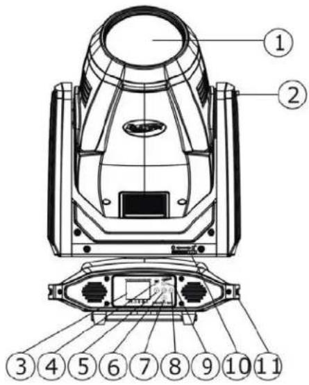
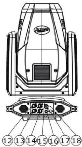
SAFETY CABLE ATTACHMENT
- Lens
- TILT Lock
- LCD Control Menu Display
- MODE/ESC Button
- LEFT Button
- ENTER Button
- DOWN Button
- RIGHT Button
- UP Button
- PAN Lock
- Handle (s)
- RJ45 Ethernet IN
- RJ45 Ethernet OUT
- 5pin DMX OUT
- 5pin DMX IN
- Fuse
- Service Port
- Power IN
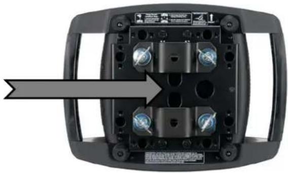
natural_image
Top-down view of a black electronic device with multiple ports and buttons, showing a gray arrow pointing to the front panel (no text or symbols visible)
ALWAYS ATTACH A SAFETY CABLE WHENEVER INSTALLING THIS DEVICE IN A SUSPENDED ENVIRONMENT TO ENSURE THE FIXTURE WILL NOT DROP IF THE CLAMP FAILS.
COLORS, GOBOS, ANIMATION
| Color Wheel | Color Flags |
| Red | Cyan |
| Green | Magenta |
| Yellow | Yellow |
| Purple | |
| Cyan | |
| Orange | |
| Magenta | |
| Light Green | |
| Pink | |
| UV Filter | |
| CTB | |
| CTO | |
| Blue |
INTERCHANGEABLE-ROTATING GLASS GOBO WHEEL 1
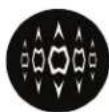
1
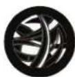
2
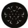
3
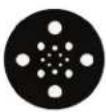
4
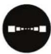
5
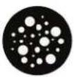
6

7

8
STATIC-FIXED METAL GOBO WHEEL 2

1 2 3 4
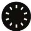
5

6

7
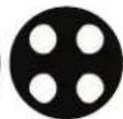
8

9
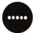
10

11

12
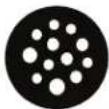
13

14
BI-DIRECTIONAL ANIMATION WHEEL
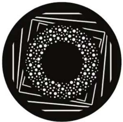
natural_image
Abstract black-and-white circular pattern with concentric squares and scattered white dots (no text or symbols)GOBO SIZE
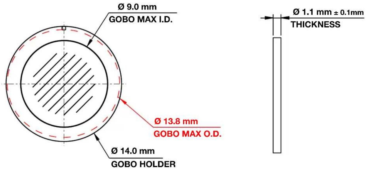
| ROTATING GLASS GOBOS - WHEEL 1 | |
| Gobo O.D. (Max. Outer Diameter) | ∅ 13.8mm |
| Gobo I.D. (Max. Image Diameter) | ∅ 9.0mm |
| Gobo Holder Diameter | ∅ 14.0mm |
| Gobo Thickness | ∅ 1.1mm ±0.1mm |
| Gobo Material | BOROFLOAT GLASS |
\*\*\* IMPORTANT NOTICE REGARDING CUSTOM GOBOS \*\*\*
Due to the high temperature optical system, special material as listed above is required for custom gobos. Due to varying manufacturing processes and tolerances, it is highly recommended to provide a gobo sample and holder from the fixture to the custom gobo vendor for accurate sizing. Extended testing of custom gobo designs is highly recommended prior to use. Contact ELATION SERVICE for further information.
ELATION SERVICE USA - Monday - Friday 8:00am to 5:00pm PST
Voice: 323-582-3322 Fax: 323-832-9142
E-mail: support@elationlighting.com
ELATION SERVICE EUROPE - Monday - Friday 08:30 to 17:00 CET
Voice: +31 45 546 85 30 Fax: +31 45 546 85 96
E-mail: support@elationlighting.eu
GOBO REPLACEMENT
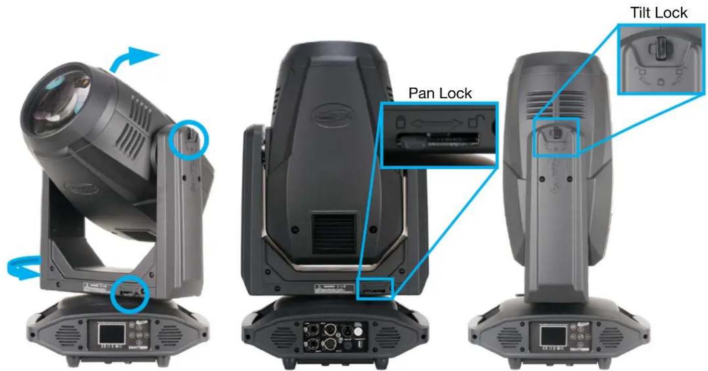
- Before removing covers, place fixture on a stable flat surface in an INDOOR DUST FREE location. Ensure moving head is locked into a neutral upright position with both PAN and TILT locks engaged.
natural_image
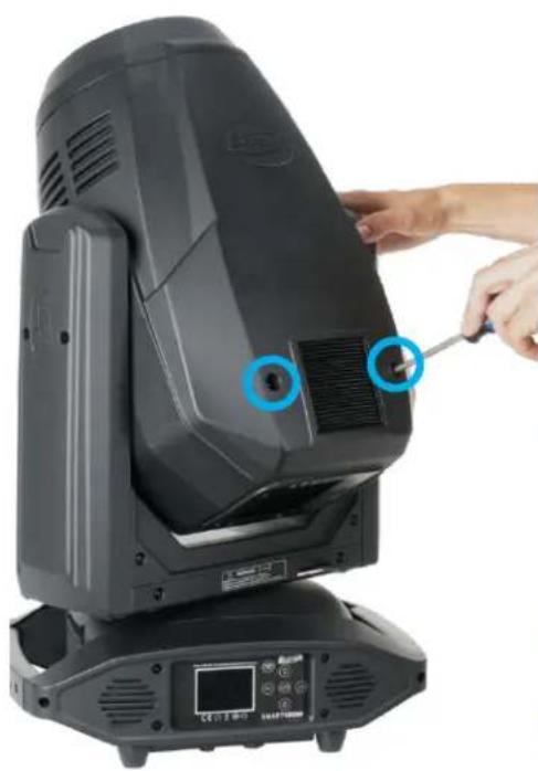
Close-up of a black triangular mechanical device with a hand adjusting its tip, showing no visible text or symbols.- Unfasten and remove the front and back panels; each are secured with (2x) 14 -turn Phillips-head screws. (These screws are integrally installed in both panels and cannot be removed.) With the panel screws unfastened, unclip their safety cables to remove them completely from the fixture. For safety and ease of access, the fixture can be locked at a 45^ angle.
natural_image
Close-up of hands installing or adjusting electronic components on a mechanical device (no visible text or symbols)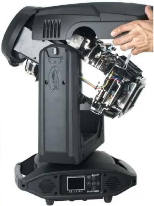
natural_image
Close-up of a black industrial robotic platform with visible internal components and a hand adjusting the handle (no text or symbols)GOBO REPLACEMENT
natural_image
Close-up of a robotic device's internal structure showing mechanical components and fan assembly (no visible text or symbols)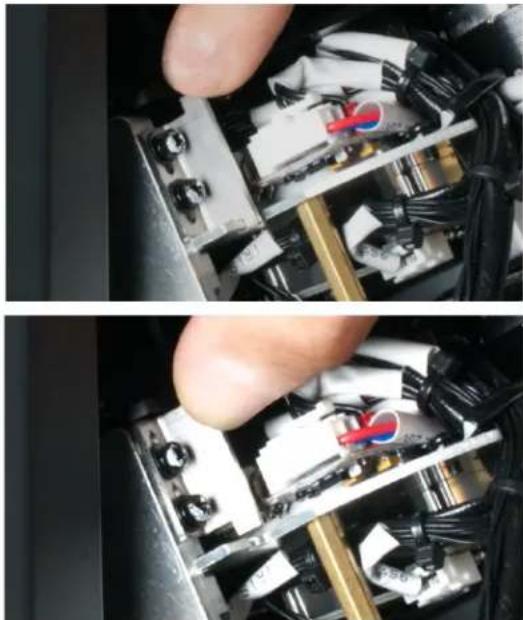
natural_image
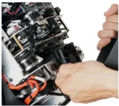
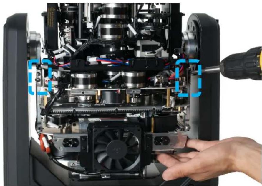
Close-up of hands installing or adjusting a mechanical component with visible wiring and components (no text or symbols)- Locate the two slotted brackets which secure the GOBO Wheel Module to the frame, each held with two Phillips-head screws. Loosen the (4x) Phillips-head screws, which will allow the slotted brackets to slide up. Slide the two slotted brackets up as shown above right.
natural_image
Close-up of hands assembling electronic components with visible wiring and mechanical parts (no text or symbols)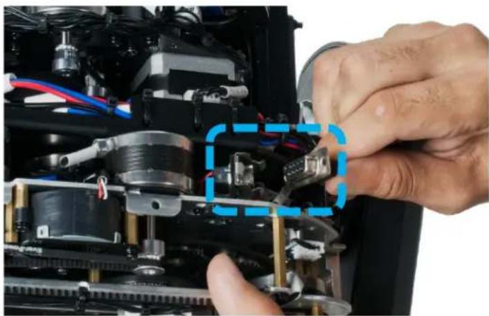
natural_image
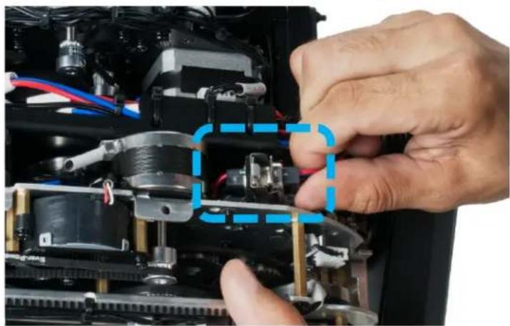
Close-up of hands assembling electronic components with visible wiring and mechanical parts (no text or symbols)- Locate the 9-pin GOBO Wheel Module connector and carefully unplug it from the connector base.

CAUTION! DO NOT USE FORCE TO REMOVE CONNECTOR!
GOBO REPLACEMENT
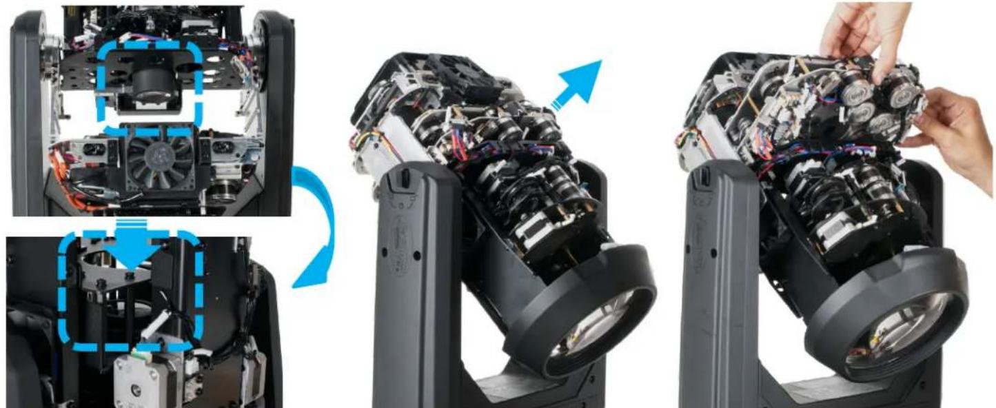
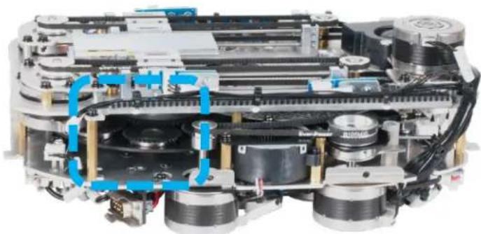
- Impeding the removal of the GOBO Wheel Module is the Zoom Lens, which is set within the lens housing aperture. Position the moving head down so the lens is facing down as well. This will allow gravity to drop the Zoom Lens out of the aperture. With the Zoom Lens dropped out of the way, carefully grip the GOBO Wheel Module, and slide it out and away to clear the mounting rails, and then carefully place the module on a stable flat surface in an INDOOR DUST FREE location.
natural_image
Internal view of a mechanical assembly with visible gears and shafts (no text or symbols)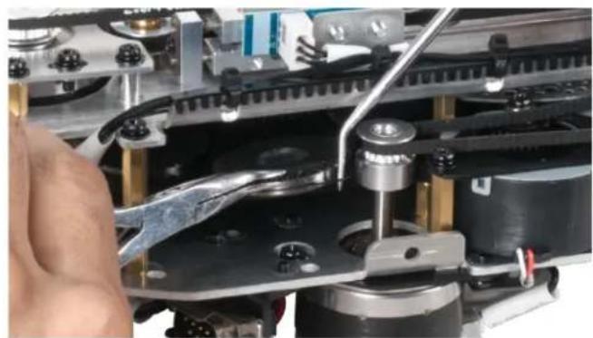
natural_image
Close-up of a mechanical assembly with a hand operating a tool, no visible text or symbols6. REPLACING A ROTATING GOBO
Locate the specific Rotating GOBO to replace. Carefully grip the GOBO Holder using needle nose pliers (or equivalent) and the ring/tab with a precision pick (or equivalent) and gently lift it slightly to pull it out and away until it fully clears the GOBO Wheel.
natural_image
Three views of a mechanical component with gear teeth and a hand holding a screwdriver (no text or symbols visible)GOBO REPLACEMENT
7. REPLACING A ROTATING GOBO
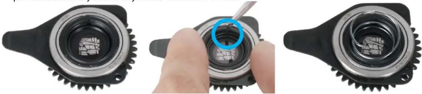
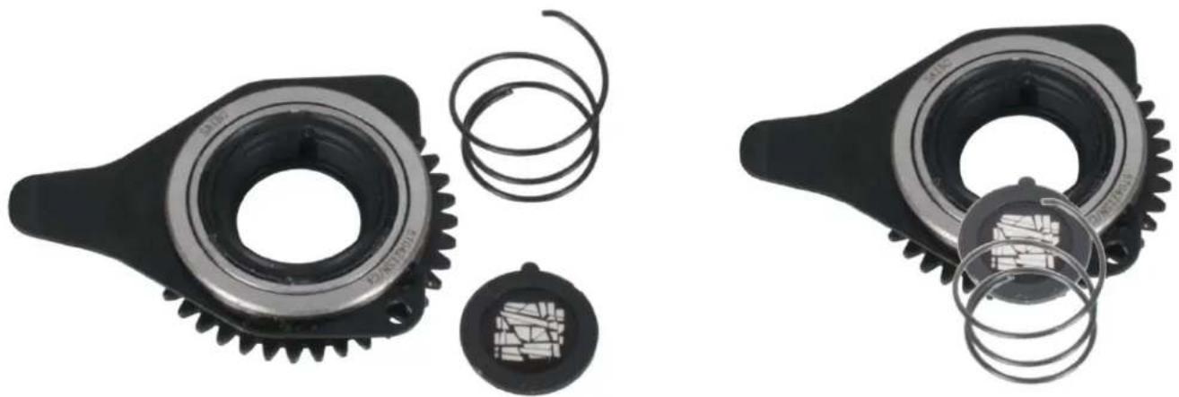
Locate the tab of the spring, and with a precision pick (or similar tool), carefully press retaining spring inward to relieve tension.
natural_image
Two mechanical gear components with visible springs and inner gears, no text or symbols present.- Remove the retaining spring and carefully separate the GOBO from the GOBO Holder. Install the replacement Rotating GOBO following the steps above in reverse order.

CAUTION: TAKE CARE NOT TO SCRATCH GOBO OR GOBO HOLDER!
LAMP REPLACEMENT
To ensure a proper/safe lamp change, carefully read all the following instructions.
USE ONLY GENUINE ORIGINAL PHILIPS™ LAMPS. OTHER BRAND LAMPS WILL CAUSE DAMAGE AND WILL VOID FIXTURE WARRANTY!

DISCONNECT THE MAIN POWER SUPPLY BEFORE REPLACING LAMP! FIXTURE MUST COOL FOR 60 MINUTES BEFORE REPLACING LAMP!
NEVER TOUCH LAMP WITH BARE HANDS, ALWAYS WEAR GLOVES! OIL FROM HANDS WILL SHORTEN LIFE OF LAMP!
MAKE SURE ALL COVERS/PANELS ARE REPLACED/SECURED BEFORE OPERATING FIXTURE TO PREVENT ANY RISK AND/OR DAMAGE TO EYE RETINA FROM UV RADIATION EXPOSIURE!
LAMP PROTECTION CIRCUITRY
The fixture LCD Menu Control Display will indicate the lamp life and related lamp warnings with each power ON, each lamp strike, and when specific lamp hours are reached. The table below provides details on each lamp life warning. Due to the extreme heat associated with the lamp and the nature of the internal optical system, it is IMPERATIVE the lamp is replaced when the LCD Menu Control Display indicates replacement is needed. This is done to protect the internal optical system as well as prevent accidental lamp explosion, which could lead to hot glass particles falling from the fixture.
| Total Lamp Hours = X - 20%LCD display will slowly blink with a YELLOW outline and the following warning for 10 mins:“LAMP LIFE left “X” hours. Please change lamp soon”Sending a DMX value of 250-251 in Channel 24 (Standard Mode) or Channel 34 (Extended Mode) from the lighting controller or pressing the OK button on the fixture control panel will clear this warning. |
| Total Lamp Hours = X up to X + 20%LCD display will slowly blink with a RED outline and the following warning for 10 mins:“LAMP LIFE exceeded by “X” hours. Please change lamp immediately”Sending a DMX value of 250-251 in Channel 24 (Standard Mode) or Channel 34 (Extended Mode) from the lighting controller or pressing the OK button on the fixture control panel will clear this warning. |
| Total Lamp Hours = X + 20% and higherLCD display will slowly blink RED Outline and the following warning:“Lamp Life “X” hours. Danger of lamp explosion and permanent fixture damage.Replace lamp immediately! User assumes all risks”This error can ONLY be cleared when the lamp hours are reset. |
LAMP REPLACEMENT
LAMP LIFE OF PHILIPS PLATINUM 400L FLEX = UP TO 4,000 HOURS
Lamp hours are calculated in real time by a smart algorithm combining periods of full output and periods of hibernation with the shutter closed. To reach 4,000 hours the fixture must be operated in average entertainment usage patterns that contain cycles of closed shutters to enter hibernation mode. On average this will allow to the fixture to reach 4,000 hours under common entertainment operation cycles as defined by Philips as 30% operation, 70% hibernation. In the rare case that the fixture Smarty would be turned on, shutter opened and never closed again the lamp life is 1,500 hours. Lamp life idle, total time and an estimated total lamp life % are provided in the display of the fixture.
LAMP INSTALLATION PROCEDURE
natural_image
Technical line drawing of a mechanical device with grid pattern and labeled part '1' (no text or symbols on the device itself)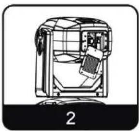
natural_image
Technical line drawing of a mechanical device with internal components and no visible text or symbols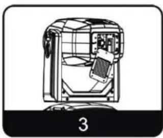
natural_image
Technical line drawing of a mechanical device with internal components and a labeled section (no text or symbols)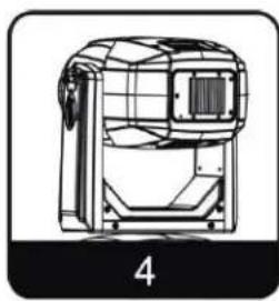
natural_image
Technical line drawing of a mechanical device with grid lines and a labeled section (no text or symbols on the device itself)
WARNING! LAMP REPLACEMENT SHOULD ONLY BE DONE BE A TRAINED TECHNICIAN.
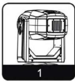
- Turn OFF power and allow approximately 60 minutes for the fixture to cool down.
- Place fixture on a stable flat surface in an INDOOR DUST FREE location, and position moving head into a 90 degree position with both PAN and TILT locks engaged.
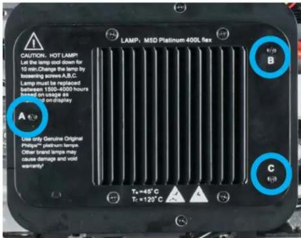
- Remove (3) Philips-head screws marked "A", "B", and "C" to remove lamp access panel.
LAMP REPLACEMENT
LAMP INSTALLATION PROCEDURE
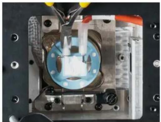
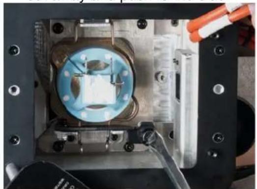
- Remove the (2x) spade receptacle-terminals connected to the lamp base.
natural_image
Close-up of a mechanical assembly with blue circular component and yellow tool, no visible text or symbols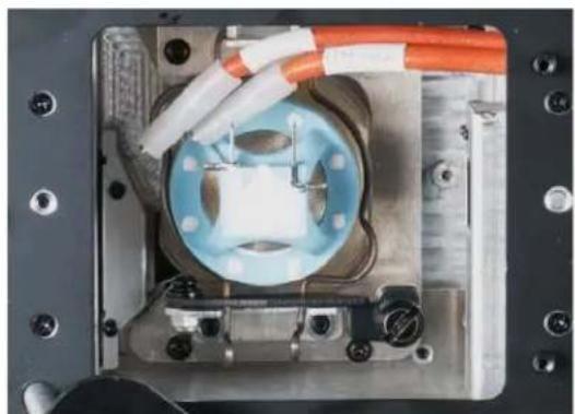
natural_image
Close-up of a mechanical assembly with blue circular component and orange wires (no visible text or symbols)- Loosen the large black slotted screw holding down the hinged lamp retention clip bar. Pull the bar out away and push to the side.
natural_image
Close-up of a mechanical assembly with a blue circular component and orange tool, no visible text or symbols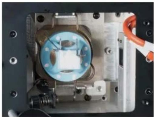
natural_image
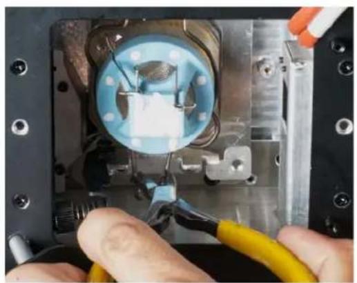
Close-up of a mechanical assembly with a blue circular component and orange-handled tool, no visible text or symbols- Squeeze the retention clip and pull clip up and away from the lamp.
natural_image
Close-up of hands using pliers to adjust a mechanical component with visible wiring and components (no text or symbols)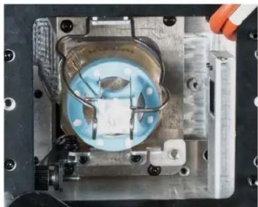
natural_image
Close-up of a mechanical assembly with a blue circular component and metal housing (no visible text or symbols)LAMP REPLACEMENT
LAMP INSTALLATION PROCEDURE
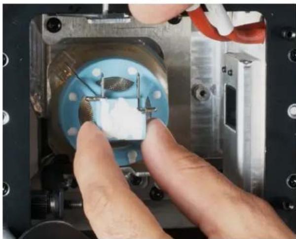
- Gently grab lamp base with thumb and index finger and pull lamp out from fixture.
natural_image
Close-up of hands using a tool to adjust or install a small component inside a metallic mechanical device (no visible text or symbols)-
Using thumb and index finger, gently install the new lamp. Position lamp so it is seated properly, then swing down the retention clip, squeezing the ends to lock/secure the lamp into place.
-
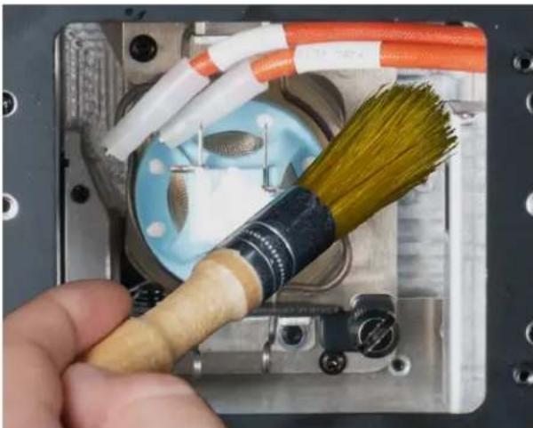
Brush away any debris as this could compromise fixture performance.
natural_image
Close-up of a hand holding a broom with yellow bristles inside a metallic mechanical housing (no visible text or symbols)-
Gently attach (2x) spade receptacle-terminals securely to the base of the lamp.
-
Replace lamp access panel and secure (3) Philips-head screws marked "A", "B", and "C".
-
Be sure to reset the LAMP HOURS in the system menu to prevent the protection circuitry from accidentally shutting off the lamp during normal operation. If the lamp protection circuitry has already been initiated and the LAMP HOURS is not reset, the “Replace the Lamp” warning will continue to flash, and fixture will eventually shut down. To reset LAMP HOURS, see instructions on the next page.
LAMP REPLACEMENT
LAMP HOURS RESET PROCEDURE
- Activate the main menu by pressing MODE/ESC and toggle to "Information".
- Press ENTER and press UP or DOWN to toggle to "Time Information".
- Press UP or DOWN to toggle to "LampTime Password" and press ENTER.
Press UP or DOWN to enter the reset pass code, "038" and press ENTER to confirm. The display will automatically revert to "LampTime Password", next press UP or DOWN to toggle down to "Clean Lamp Time".
- Press ENTER and select "ON". The lamp timer has now been reset, press MODE/ESC to exit the menu and return to the home screen.
LAMP OPTIMIZATION
Unlike traditional discharge lamps the Philips MSD Platinum 400L FLEX lamp does NOT require optimization. The lamp orientation and optimization procedure has been preset during the manufacturing process of the lamp. The lamp is NOT a hot-restrike lamp therefore, you must wait approximately 10 minutes before attempting to restrike once it has been turned off.
FIXTURE INSTALLATION

FLAMMABLE MATERIAL WARNING
Keep fixture minimum 5.0 feet (1.5m) away from flammable materials and/or pyrotechnics.

ELECTRICAL CONNECTIONS
A qualified electrician should be used for all electrical connections and/or installations.

MINIMUM DISTANCE TO OBJECTS/SURFACES MUST BE 49.2 FEET (15 METERS)

MINIMUM DISTANCE OF INFLAMMABLE MATERIALS FROM THE SURFACE 1.6 FEET (0.5 METER)

MAXIMUM TEMP OF EXTERNAL SURFACE 248°F (120°C)

DO NOT INSTALL THE FIXTURE IF YOU ARE NOT QUALIFIED TO DO SO!
Fixture MUST be installed following all local, national, and country commercial electrical and construction codes and regulations.
Before rigging/mounting a single fixture or multiple fixtures to any metal truss/structure or placing the fixture(s) on any surface, a professional equipment installer MUST be consulted to determine if the metal truss/structure or surface is properly certified to safely hold the combined weight of the fixture(s), clamps, cables, and accessories.
Overhead rigging requires extensive experience, including amongst others calculating working load limits, installation material being used, and periodic safety inspection of all installation material and the fixture. If you lack these qualifications, do not attempt the installation yourself. Improper installation can result in bodily injury.
Fixture ambient operating temperature range is 14° to 113°F. (-10° to 45°C)
Do not use the fixture under or above this temperature.
Fixture(s) should be installed in areas outside walking paths, seating areas, or away from areas were unauthorized personnel might reach the fixture by hand.
NEVER stand directly below the fixture(s) when rigging, removing, or servicing.
Overhead fixture installation must always be secured with a secondary safety attachment, such as an appropriately rated safety cable.
Allow approximately 60 minutes for the fixture to cool down before serving.
FIXTURE INSTALLATION
OMEGA BRACKETS INSTALLATION
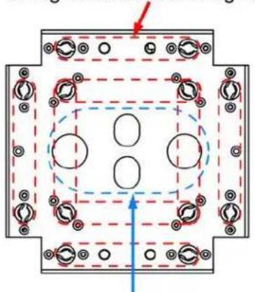
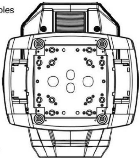
Insert the Omega Brackets into the matching holes on the bottom of the fixture. Note that there are 8 possible locations. Secure the Omega Brackets to the fixture by turning each quick-lock fastener 14 turn clockwise; making sure the fastener is completely locked. Omega Brackets can be installed into the fixture base as illustrated below.
Omega Bracket Mounting Holes
natural_image
Pure mechanical assembly diagram with no text, numbers, or symbolsSafety Cable Rigging Points
natural_image
Technical line drawing of a mechanical component with mounting holes and internal grid (no text or symbols)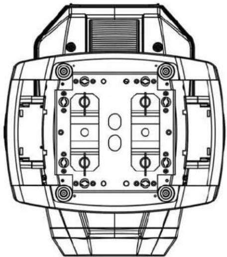
natural_image
Technical line drawing of a mechanical component with internal compartments and mounting holes (no text or symbols)CLAMP INSTALLATION
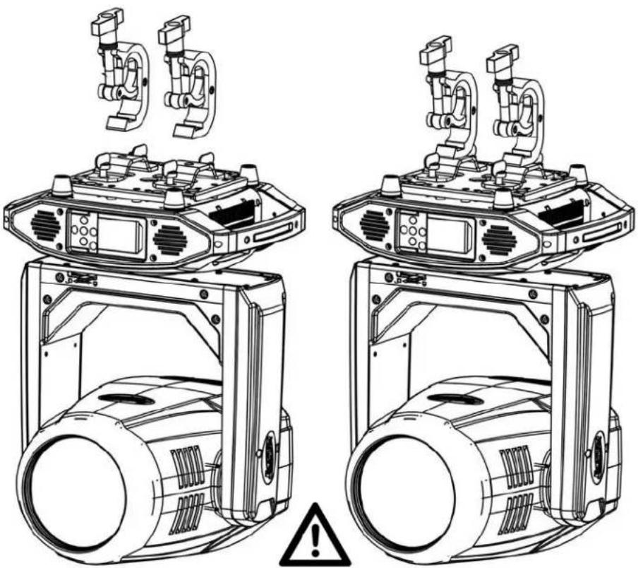
When mounting fixture to truss, be sure to secure an appropriately rated professional grade rigging clamp to the included Omega Brackets using an M12 screw fitted through the center hole of the Omega Brackets. The fixture provides a built-in rigging point for a SAFETY CABLE. Be sure to only use one of the designated rigging points for the safety cable and never secure a safety cable to a carrying handle.
natural_image
Technical line drawings of a mechanical device with two top views and a warning symbol (no text or labels)ALWAYS ATTACH AN APPROPRIATELY RATED SAFETY CABLE (NOT INCLUDED) THAT MEETS ALL LOCAL, NATIONAL, AND COUNTRY CODES AND REGULATIONS WHENEVER INSTALLING FIXTURE IN A SUSPENDED ENVIRONMENT!
FIXTURE INSTALLATION
RIGGING
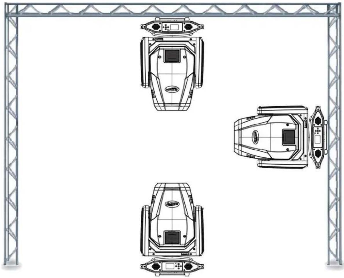
Overhead rigging requires extensive experience, including among others calculating working load limits, installation material being used, and periodic safety inspection of all installation material and the fixture. If you lack these qualifications, do not attempt the installation yourself. Improper installation can result in bodily injury.
natural_image
Technical line drawing of four identical mechanical or industrial components mounted on a metal truss structure (no text or symbols)FIXTURE INSTALLATION
ART-NET | sACN CONNECTION
When connecting fixture to a network switch to control multiple devices, a Gigabit Ethernet Switch that supports IGMP (Internet Group Management Protocol) is required. Using a Gigabit Ethernet Switch that does not support IGMP can cause erratic behavior of all connected devices to the switch. Click link below for more information about IGMP.
https://en.wikipedia.org/wiki/Internet_Group_Management_Protocol
POTENTIAL INTERNAL FIXTURE DAMAGE FROM EXTERNAL SOURCES OF LIGHT BEAMS
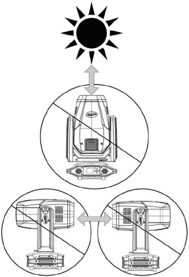
External sources of light beams from direct sunlight, lighting moving head fixtures, and lasers, which are focused directly on the exterior housing and/or penetrate the front lens opening of ELATION lighting fixtures, can cause severe internal damage including burning to optics, dichroic color filters, glass and metal gobos, prisms, animation wheels, frost filters, iris, shutters, motors, belts, wiring, discharge lamps, and LEDs.
This issue is not specific only to ELATION lighting fixtures, it is a common issue with lighting fixtures from all manufacturers. Although there is no true way to fully prevent this issue from happening, the guidelines below can prevent any potential damage from occurring if followed. Contact ELATION Service for more details.
DO NOT EXPOSE THE FIXTURE AND/OR FRONT LENS OPENING TO LIGHT BEAMS FROM DIRECT SUNLIGHT, OTHER LIGHTING MOVING HEAD FIXTURES, AND LASERS WHILE UNPACKING, INSTALLATION, USE, AND EXTENDED IDLE TIMES OUTDOORS. DO NOT FOCUS A LIGHT BEAM FROM ONE LIGHTING FIXTURE DIRECTLY TOWARDS ANOTHER.
flowchart
graph TD
    A["Sun"] --> B["Device with Sensor"]
    B --> C["Device with Sensor"]
    C --> D["Device with Sensor"]
    D --> E["Device with Sensor"]
    style A fill:#f9f,stroke:#333
    style B fill:#ccf,stroke:#333
    style C fill:#cfc,stroke:#333
    style D fill:#fcc,stroke:#333
    style E fill:#cff,stroke:#333
SUN PROTECTION MODE
The fixture incorporates an automatic protection from harmful sunlight, which can damage a fixture's internal components from extended exposure. Fixtures use an internal sensor to determine their physical orientation, then reorient the fixture towards the ground to prevent sunlight from entering the lens.
This automatic feature only works when the fixture is powered. If the fixture is unpowered during setup, it is necessary to manually reorient the lenses away from the sun and aim them towards the ground. Even a few minutes of sun exposure can cause damage inside the fixture.
The Sun Protection setting is accessed via the "No DMX Status" menu.
The automatic sun protection positioning is activated under the following conditions:
- Power on without DMX signal: the fixture always starts in sun protection mode.
- No DMX Status "Sun Protection": the fixture enters sun protection mode after approximately 3 minutes.
- Remote DMX control: the sun protection position can be temporarily activated from the lighting console without the need to create a custom position preset. The fixture senses the correct ground orientation. This means that fixtures already facing the ground may not move their heads.
Hold "Sun Protect Position" for 3s to set the fixture to the sun protection position.
Sun protection status displays as "Sun Protection: Active".
The sun protection position deactivates under the following conditions:
- Connect DMX signal.
- Remote DMX control: Hold "Sun Protection Off" for 3s.
To avoid harsh or jarring movements, the sun protection position always uses a 5-second fade time when it is activated or deactivated.
HIBERNATION MODE
To reduce wear on the fixture and its components, this mode disables motors and most electronics. Set the hibernation mode countdown time in the Display Menu: "Status Settings / Personality / Hibernation". Hibernation can be fully disabled.
The hibernation mode activates under the following conditions:
-
Loss of DMX: the fixture enters hibernation after the timeout expires. Default is 15 minutes.
-
Remote DMX control: Hold "Hibernate Fixture" for 3s
The hibernation mode deactivates under the following conditions:
-
Connect DMX Signal
-
Remote DMX control: Hold "Hibernate Off" for 3s
The fixture will perform a full calibration cycle, then assume the current DMX status.
Please note that the Hibernation does not change the PT position of the fixtures, allowing the user to set the desired position and then issue the Hibernate command.
To ensure the fixture is protected from harmful sunrays it is recommended to either leave the "No DMX Status" in "Sun Protection" (so the fixture is already in the correct position after 3 minutes of DMX loss) or set the fixture to a safe Tilt position manually first before hibernation.
Burn and heat damage to the fixture's interior components due to external light sources (sun or other fixtures shining into the lens) is never covered under the manufacturer's warranty.
SYSTEM MENU
The fixture includes an easy to navigate system menu. The control panel (see image below) located on the front of the fixture, provides access to the main system menu and is where all necessary system adjustments are made to the fixture. During normal operation, pressing MODE/ESC button once will access the fixture's main menu. Once in the main menu you can navigate through the different functions and access the sub-menus with the UP, DOWN, RIGHT, and LEFT buttons. Once you reach a field that requires adjusting, press the ENTER button to activate that field and use the UP and DOWN buttons to adjust the field. Pressing the ENTER button once more will confirm your setting. You may exit the main menu at any time without making any adjustments by pressing the MODE/ESC button.
To access the LCD Menu Control Display via the internal battery, press and hold the MODE/ESC button for 5 seconds. The LCD Menu Control Display will shut OFF automatically about 1 minute from the last button press.
Press

natural_image
Empty white rectangle with black border (no text or symbols)






SMARTY MAX
ELATION SMARTY MAX SYSTEM MENU
| Features are subject to change without notice. *Rotation direction (Clockwise or Counterclockwise) of effects depends on orientation of the fixture head and Pan/Tilt settings. | ||||
| MAIN MENU | SUB MENU | OPTIONS / VALUES (Default Settings in BOLD) | DESCRIPTION | |
| FUNCTION | Set Dmx Address | A001~AXXX | DMX Address Setting | |
| Dmx Value | PAN...... | DMX Value Display | ||
| Secondary Mode | Secondary1, Secondary2, Secondary3 | Secondary Setting | ||
| Auto Program | Primary / Alone | Auto Program | ||
| INFORMATION | Time Information | Current Time | xxxx(Hours) | Fixture Run Time From Power ON |
| Total Run Time | xxxx (Hours) | Fixture Total Run Time | ||
| Last Run Time | xxxx (Hours) | Fixture Last Run Time | ||
| Lamp Time Info | Total Time xxxx (Hours) | Total Lamp Time Usage | ||
| Active Time xxxx (Hours) | Active Lamp Time Usage | |||
| Idle Time xxxx (Hours) | Idle Lamp Time | |||
| Lamp Life (% Percent) | Lamp Life | |||
| LastRun Password | Password = 038 | (PSWD Required) | ||
| Clear Last Run | ON / OFF | Clear Fixture Last Run Time | ||
| LampTimePassword | Password = 038 | (PSWD Required) | ||
| Clear Lamp Time | ON / OFF | Clear Lamp Run Time | ||
| Temperature Info | Head Temperature | xxx C° / F° | Temperature in Fixture Head | |
| Base Temperature | xxx C° / F° | Temperature in Fixture Base | ||
| Ethernet IP | xxx . xxx . xxx . xxx | xxx . xxx . xxx . xxx | Displays Fixture Ethernet Address | |
| Fan Info | 1U_FAN1:xxxx RPM, ... | Speeds of Head/Base Fans | ||
| Software Version | Vx.x | Software Version | ||
| Error Info | Error Record 1 ~ Error Record 10 | Fixture Last 10 Error Codes | ||
| LAMP CONTROL | Lamp On/Off | ON/OFF | Lamp ON/OFF | |
| Automatic On | ON/OFF | Lamp ON/OFF when Power ON | ||
| Lamp On via DMX | ON/OFF | Lamp ON via DMX | ||
| Lamp Off via DMX | ON/OFF | Lamp OFF via DMX | ||
| Lamp Power Mode | 480W, 470W, 370W | Lamp Power Mode | ||
| PERSONALITY | Status Settings | Address via DMX | ON/OFF | Address Via DMX |
| No DMX Status | Close / Hold / Auto/ SunProt | Fixture State When NO DMX Signal | ||
| Pan Reverse | ON/OFF | Pan Reverse Movement | ||
| Tilt Reverse | ON/OFF | Tilt Reverse Movement | ||
| Pan Degree | 630/540 | Pan Degree Select | ||
| Feedback | ON/OFF | Movement Feedback | ||
| Movement Speed | Normal, Slow | Set Movement Speed | ||
| CMY Speed | Fast / Normal | Select CMY Speed | ||
| P/T Brake Mode | Smooth, Fast | Set Pan / Tilt Brake Mode | ||
| Hibernation | OFF, 01M~99M, 15M | Standby Mode | ||
| Service Setting | Password | Password=050 | Service Password | |
| Clear Err. Info | ON/OFF | Clear Error Info (PSWD Required) | ||
| DFLT Pow. LampOn | ON/OFF | Set Lamp Default Power State | ||
| DFLT Pow. Efly On | ON/OFF | Set E-FLY Default Power State (E-FLY Optional) | ||
| USB Update | YES/NO | Service Port - Software Updates | ||
| Display Setting | Shutoff Time | 02~60m 05m | Display Shut Off Time | |
| Display Reverse | ON/OFF/AUTO | Display Reverse 180° | ||
| Key Lock | ON/OFF | Key Lock | ||
| Temperature C/F | Celsius/Fahrenheit | Temperature Switch Between C° / F° | ||
| Initial Status | PAN =XXX... | Initial Effect Position | ||
| Select Signal | E-FLY Off, DMX & E-FLY, E-FLY & Out, Art-Net, sACN | Activate Signal Protocol (E-FLY Optional) | ||
| Ethernet IP | XXX . XXX . XXX . XXX | Ethernet IP | ||
| Ether Mask IP | XXX . XXX . XXX . XXX | Ethernet Mask IP | ||
| Set Universe | 000 - 32767 | Set Art-Net Universe | ||
| Set E-FLY Chn | 00 - 14 | Set E-FLY Channel (E-FLY Optional) | ||
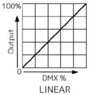
| Dimmer Curve | Linear, Square, InverseSquare, S-Curve | Set Dimmer Curve Mode | ||
| Reset Default | ON/OFF | Password = 011 | Restore Factory Settings (PSWD Required) | |
| ELATION SMARTY MAX SYSTEM MENU | ||||
| Features subject to change without notice. *Rotation direction (Clockwise or Counterclockwise) of effects depends on orientation of the fixture head and Pan/Tilt settings. | ||||
| MAIN MENU | SUB MENU | OPTIONS / VALUES (Default Settings in BOLD) | DESCRIPTION | |
| Reset Function | Reset All | Reset All Motors | ||
| Reset Pan&Tilt | Reset Pan/Tilt | |||
| Reset Colors | Reset Color Wheel | |||
| Reset Gobos | Reset Gobos | |||
| Reset Shutter | Reset Shutter | |||
| Reset Others | Reset Other Motors | |||
| Effect Adjust | Test Channel | PAN ...... | Test function | |
| Manual Control | PAN =XXX, ...... | Fine Adjustments | ||
| Calibration | Calibration Password PAN = XXX, ... | Password 050 (PSWD Required) | ||
| User Mode Set | User Mode | Standard Mode | DMX Channel Modes | |
| Extended Mode | ||||
| Edit Program | Select Program | Auto Pro Part1 = Program 1~10 (Program 1) | Select Programs To Be Run | |
| Auto Pro Part2 = Program 1~10 (Program 2) | ||||
| Auto Pro Part3 = Program 1~10 (Program 3) | ||||
| Edit Program | Program 1 | Program Test | Testing Program | |
| : | Step 01=SCxxx | Program In Loop | ||
| Program 10 | Step 64=SCxxx | Save and Exit | ||
| Edit Scenes | Edit Scene 001 ~ Edit Scene 250 | Pan,Tilt,...... | Save and Automatically Return | |
| --Fade Time-- --Scene Time-- | Manual Scenes Edit | |||
| Input By Out | Stores Scenes via Ext DMX Console | |||
| Rec. Controller | XX~XX | Automatic Scenes Recorder | ||

ALTHOUGH E-FLY SETTINGS MAY APPEAR IN THE SYSTEM MENU, THIS FEATURE IS NOT ACTIVATED. E-FLY WIRELESS DMX IS AN OPTIONAL FEATURE WHICH MUST BE ACTIVATED IN THE SERVICE MENU.
PLEASE CONTACT ELATION SERVICE FOR FURTHER DETAILS.
SYSTEM MENU
PERSONALITY - Status Settings - Address Via DMX
When ON, define the desired DMX address via an external controller.
NOTE: This process assumes the fixture DMX address is set to 001. If fixture DMX address is not at 001, you must adjust the channel numbers accordingly in order for this feature to work.
For example: if your fixture address is 010, then Channel 1 becomes Channel 10, Channel 2 becomes Channel 11, and Channel 3 becomes Channel 12.
- Connect the fixture to the external controller and power ON.
- Set the DMX value of Channel 1 on the controller to (7).
-
Set the DMX value of Channel 2 on the controller to (7) or (8).
When set to (7), the DMX address can be set between (1) and (255).
When set to (8), the DMX address can be set between (256) and (511). -
Using Channel 3 on the controller set the desired DMX address of the fixture.
Example 1: If the desired DMX address is 57, set Channel 1 to a value of (7), set Channel 2 to a value of (7), and then set Channel 3 to a value of (57).
Example 2: If the desired DMX address is 420, set Channel 1 to a value of (7), set Channel 2 to a value of (8), and then set Channel 3 to a value of (164). (256+164=420)
- After setting Channel 3 to the desired DMX address value, wait for approximately 20 seconds (some fixtures may require a longer time) for the fixture to complete the address reset function.
PERSONALITY - Service Setting - Password (050)
The Service Password MUST be entered in order to access the service menus.
PERSONALITY – Service Setting – USB Update
To update the fixture software via the UPDATE/SERVICE PORT, follow steps below.

ONLY QUALIFIED TECHNICIANS SHOULD PERFORM THIS FUNCTION! NOTE ALL MENU SETTINGS BEFORE UPDATING SOFTWARE! FIXTURE SOFTWARE CAN NOT BE DOWNGRADED! DOWNLOAD FIXTURE SOFTWARE TO PC ONLY! (NO MAC SUPPO PLEASE CONTACT ELATION SERVICE FOR FURTHER INFORMAT
- Copy fixture software update file from a PC computer to a compatible USB flash drive. Make sure only the fixture software update file is stored on the USB flash drive.
- Disconnect DMX, Art-Net, and E-FLY connections and power the fixture ON.
- Insert USB flash drive into the UPDATE/SERVICE PORT on the rear connection panel.
- Navigate to the Personality main menu Service Setting / USB Update sub menu.
- Select the software file name on the menu display and press ENTER.
- Select YES to begin update process and Updating...% will show on the menu display.
- After file is uploaded, the fixture will check the software which will take some time.
The fixture will perform a reset process when the software update process is complete. - Remove the USB flash drive and make necessary system menu setting adjustments.
SYSTEM MENU
PERSONALITY - Display Setting – Key Lock
When ON, Control Panel buttons lock automatically after exiting main menu for 15 seconds. To unlock, keep MODE/ESC button pressed for 3 seconds.
PERSONALITY - Reset Default

ONLY QUALIFIED TECHNICIANS SHOULD PERFORM THIS FUNCTION!
This function restores all fixture settings to the factory default settings. The password is 011 and must be entered each time a reset is performed.
EFFECT ADJUST – Test Channel
Auto test each individual channel function independently from the DMX control board.
EFFECT ADJUST – Manual Control
Select and manually test and fine adjust each individual channel function
Independently from DMX control board. This function will center PAN and TILT motors and set dimmer to 100%. PAN and TILT functions will still operate if the fixture needs to be positioned to a flat clear surface. With the individual functions, you can focus the light on a flat surface (wall) and perform fine adjustments.
EFFECT ADJUST – Calibration

ONLY QUALIFIED TECHNICIANS SHOULD PERFORM THIS FUNCTION!
This function allows small adjustments to be made to the Pan, Tilt, and Zoom movements to compensate for ware or in the event a sensor has been knocked slightly out of place. Because improper use of this function can result in undesired operation this function has been password protected. The password is 050 and must be entered each time the calibration menu function is entered. Because calibration is an extremely delicate procedure, instructions on performing this action are left out of this manual. For a first-time calibrator, please contact our customer support team for step-by-step instructions.
SYSTEM MENU
EDIT PROGRAM – Rec. Controller
The fixture features an integrated DMX-recorder by which you can transmit the programmed scenes from your DMX-controller to the moving head. Adjust the desired scene numbers via the encoder (from – to). When you call up the scenes at your controller, they will automatically be transmitted to the moving head.
EDIT PROGRAM – Record Controller – Working with Built-In Programs
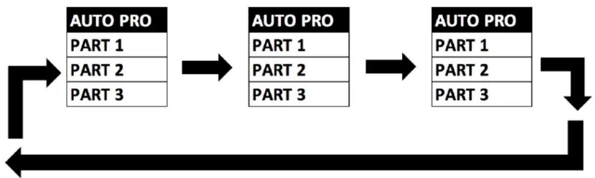
A Primary unit can send up to 3 different data groups to the Secondary units, i.e. a Primary unit can start 3 different Secondary units, which run 3 different programs. The Primary unit sends the 3 program parts in a continuous loop.
flowchart
graph TD
    A["AUTO PRO\nPART 1\nPART 2\nPART 3"] --> B["AUTO PRO\nPART 1\nPART 2\nPART 3"]
    B --> C["AUTO PRO\nPART 1\nPART 2\nPART 3"]
    C --> D["Downward arrow"]
The Secondary unit receives data from the Primary unit according to the group which the Secondary unit was assigned to. If e.g. a Secondary unit is set to “Secondry 1” in the menu “Set to Secondry”, the Primary unit sends “Auto Program Part 1” to the Secondary unit.
If set to “Secondary 2”, the Secondary unit receives “Auto Program Part 2”.
SYSTEM MENU
EDIT PROGRAM – Record Controller – Working with Built-In Program [continued]
To start an Auto Program, proceed as follows:
1. Secondary Setting
Select "Function Mode".
Press ENTER to confirm.
Select "Set to Secondary".
Press ENTER to confirm.
Select "Secondary 1", "Secondary 2" or "Secondary 3".
Press ENTER to confirm.
Press MODE/ESC in order to return to the main menu.
2. Automatic Program Run
Select "Function Mode".
Press ENTER to confirm.
Select "Auto Program".
Press ENTER to confirm.
Select "Primary" or "Alone".
Press ENTER to confirm.
Press MODE/ESC in order to return to the main menu.
3. Program Selection for Auto Pro Part
Select "Edit Program".
Press ENTER to confirm.
Select "Select Programs".
Press ENTER to confirm.
Select “Auto Pro Part 1”, “Auto Pro Part 2” or “Auto Pro Part 3” and select which Secondary program is to be sent. Selection “Part 1” means, that the Secondary unit runs the same program as the primary units.
Press ENTER to confirm.
Press MODE/ESC in order to return to the main menu.
4. Program Selection for Edit Program
Select "Edit Program".
Press ENTER to confirm.
Select "Edit Program".
Press ENTER to confirm.
Select the desired program to edit specific scenes into a specific program.
Press ENTER to confirm.
Press MODE/ESC in order to return to the main menu.
SYSTEM MENU
EDIT PROGRAM – Record Controller – Working with Built-In Program [continued]
5. Automatic Scene Recording
Select "Edit Program".
Press ENTER to confirm.
Select "Edit Scenes".
Select desired scene numbers. A maximum of 250 scenes can be programmed.
Press ENTER to confirm.
Press MODE/ESC in order to return to the main menu.
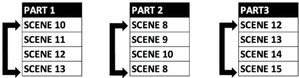
Example:
Program 2 includes scenes: 10, 11, 12, & 13
Program 4 includes scenes: 8, 9, & 10
Program 6 includes scenes: 12, 13, 14, & 15
Auto Pro Part 1 is Program 2
Auto Pro Part 2 is Program 3
Auto Pro Part 3 is Program 6
The 3 Secondary groups run the Auto Program in certain time segments. (See chart below)
flowchart
graph LR
    A["PART 1\nSCENE 10\nSCENE 11\nSCENE 12\nSCENE 13"] --> B["PART 2\nSCENE 8\nSCENE 9\nSCENE 10\nSCENE 8"]
    B --> C["PART 3\nSCENE 12\nSCENE 13\nSCENE 14\nSCENE 15"]
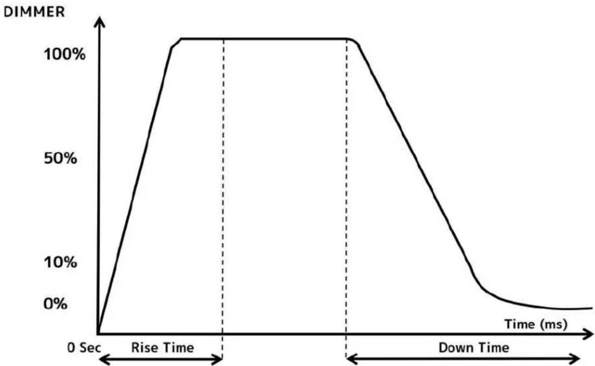
DIMMER MODE
line
| Time (ms) | DIMMER | | --------- | ------ | | 0 | 0% | | Rise | 100% | | Down | 0% || Dimming Curve Ramp Effect | 0 sec Fade Time | 1 sec Fade Time | ||
255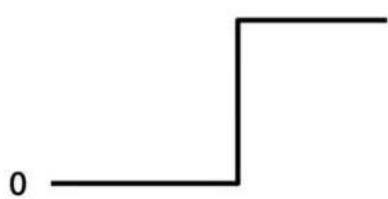 | 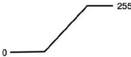 | |||
| Rise Time (ms) | Down Time (ms) | Rise Time (ms) | Down Time (ms) | |
| Standard (default) | 0 | 0 | 0 | 0 |
| Stage | 780 | 1100 | 1540 | 1660 |
| TV | 1180 | 1520 | 1860 | 1940 |
| Architectural | 1380 | 1730 | 2040 | 2120 |
| Theatre | 1580 | 1940 | 2230 | 2280 |
| Stage 2 | 0 | 1100 | 0 | 1660 |
line
| DMX % | Output | |-------|--------| | 0 | 0 | | 100 | 100 |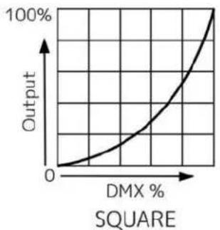
line
| DMX % | Output | |-------|--------| | 0 | 0 | | 100 | 100 |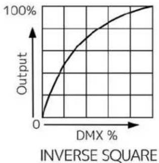
line
| DMX % | Output | |-------|--------| | 0 | 0 | | >100 | 100 |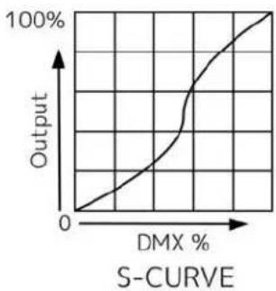
line
| DMX % | Output | |-------|--------| | 0 | 0 | | > DMX % | 100% |DMX TRAITS
| Features subject to change without notice.*Rotation direction (Clockwise/Counterclockwise) and control of effects depends on head orientation and Pan/Tilt settings. | |||||
| Standard | Extended | Value | Function | Default | Snap |
| 1 | 1 | 0-255 | PAN Movement 8bit: Pan Movement | ||
| 2 | 2 | 0-255 | Pan Fine 16bit: Fine control of Pan movement | ||
| 3 | 3 | 0-255 | TILT Movement 8bit: Tilt Movement | ||
| 4 | 4 | 0-255 | Tilt Fine 16bit: Fine control of Tilt Movement | ||
| 5 | 5 | 0-255 | Cyan: (0-100% Cyan) | ||
| 6 | 0-255 | Cyan Fine: Cyan Fine | |||
| 6 | 7 | 0-255 | Magenta: (0-100% Magenta) | ||
| 8 | 0-255 | Magenta Fine: Magenta Fine | |||
| 7 | 9 | 0-255 | Yellow: (0-100% Yellow) | ||
| 10 | 0-255 | Yellow Fine: Yellow Fine | |||
| 8 | 11 | 0-255 | CTO: (0-100% CTO | ||
| 12 | 0-255 | CTO Fine: CTO Fine | |||
| 9 | 13 | Color Wheel: | |||
| 0-10 | Open | ||||
| 11-19 | Red | ||||
| 20-28 | Green | ||||
| 29-37 | Yellow | ||||
| 38-46 | Purple | ||||
| 47-55 | Light Blue | ||||
| 56-64 | Orange | ||||
| 65-73 | Magenta | ||||
| 74-82 | AQUA | ||||
| 83-91 | Pink | ||||
| 92-100 | UV | ||||
| 101-109 | CTB | ||||
| 110-118 | CTO | ||||
| 119-127 | Deep Blue | ||||
| Color Scroll | |||||
| 128-180 | Clockwise, fast→slow | ||||
| 181 | Stop | ||||
| 182-234 | Counter-clockwise, slow→fast | ||||
| Random Slots | |||||
| 235-239 | Fast | ||||
| 240-244 | Medium | ||||
| 245-249 | Slow | ||||
| 250-255 | Open | ||||
| 14 | 0-255 | Color Wheel Fine:Fine Control of Color Wheel position | |||
| Standard | Extended | Value | Function | Default | Snap |
| 10 | 15 | Rotating Gobo | |||
| 0-10 | Beam open | ||||
| 11-21 | Spot open | ||||
| 22-31 | Rot. gobo 1 | ||||
| 32-41 | Rot. gobo 2 | ||||
| 42-51 | Rot. gobo 3 | ||||
| 52-61 | Rot. gobo 4 | ||||
| 62-71 | Rot. gobo 5 | ||||
| 72-81 | Rot. gobo 6 | ||||
| 82-91 | Rot. gobo 7 | ||||
| 92-101 | Rot. gobo 8 | ||||
| 102-112 | Rot. gobo 1 shake | ||||
| 113-123 | Rot. gobo 2 shake | ||||
| 124-134 | Rot. gobo 3 shake | ||||
| 135-145 | Rot. gobo 4 shake | ||||
| 146-156 | Rot. gobo 5 shake | ||||
| 157-167 | Rot. gobo 6 shake | ||||
| 168-178 | Rot. gobo 7 shake | ||||
| 179-189 | Rot. gobo 8 shake | ||||
| 190-221 | Scroll CW fast to slow | ||||
| 222-223 | Stop | ||||
| 224-255 | Scroll CCW slow to fast | ||||
| 11 | 16 | Rotating Gobo Index, Rotation | |||
| 0-127 | Gobo indexing | ||||
| 128-189 | Clockwise gobo scroll from fast to slow | ||||
| 190-193 | No rotation | ||||
| 194-255 | Counter-clockwise gobo scroll from slow to fast | ||||
| 17 | 0-255 | Rotating gobo fine indexing: Fine indexing | |||
| 12 | 18 | Fixed gobos1 | |||
| 0-7 | Open | ||||
| 8-14 | Gobo 1 | ||||
| 15-21 | Gobo 2 | ||||
| 22-28 | Gobo 3 | ||||
| 29-35 | Gobo 4 | ||||
| 36-42 | Gobo 5 | ||||
| 43-49 | Gobo 6 | ||||
| 50-56 | Gobo 7 | ||||
| 57-63 | Gobo 8 | ||||
| 64-70 | Gobo 9 | ||||
| 71-77 | Gobo 10 | ||||
| 78-84 | Gobo 11 | ||||
| 85-91 | Gobo 12 | ||||
| 92-98 | Gobo 13 | ||||
| 99-105 | Gobo 14 | ||||
| 106-111 | Gobo 1 shake slow to fast | ||||
| 112-117 | Gobo 2 shake slow to fast | ||||
| 118-123 | Gobo 3 shake slow to fast | ||||
| 124-129 | Gobo 4 shake slow to fast | ||||
| 130-135 | Gobo 5 shake slow to fast | ||||
| 136-141 | Gobo 6 shake slow to fast | ||||
| 142-147 | Gobo 7 shake slow to fast | ||||
| 148-153 | Gobo 8 shake slow to fast | ||||
| 154-159 | Gobo 9 shake slow to fast | ||||
| 160-165 | Gobo 10 shake slow to fast | ||||
| 166-171 | Gobo 11 shake slow to fast | ||||
| 172-177 | Gobo 12 shake slow to fast | ||||
| 178-183 | Gobo 13 shake slow to fast | ||||
| 184-189 | Gobo 14 shake slow to fast | ||||
| 190-221 | Scroll CW fast to slow | ||||
| 222-223 | Stop | ||||
| 224-255 | Scroll CCW slow to fast | ||||
| 19 | 0-255 | Fixed gobo indexing Fine 1: Fine indexing | |||
| 13 | 20 | Rotating Prism,Prism/Gobo macros: | |||
| 0-63 | Open | ||||
| 64-95 | Prism 8x | ||||
| 96-127 | Prism 6 Linear | ||||
| 128-135 | Macro1 | ||||
| 136-143 | Macro2 | ||||
| 144-151 | Macro3 | ||||
| 152-159 | Macro4 | ||||
| 160-167 | Macro5 | ||||
| 168-175 | Macro6 | ||||
| 176-183 | Macro7 | ||||
| 184-191 | Macro8 | ||||
| 192-199 | Macro9 | ||||
| 200-207 | Macro10 | ||||
| 208-215 | Macro11 | ||||
| 216-223 | Macro12 | ||||
| 224-231 | Macro13 | ||||
| 232-239 | Macro14 | ||||
| 240-247 | Macro15 | ||||
| 248-255 | Macro16 | ||||
| 14 | 21 | Rotating prism index,rotating gobo rotation: | |||
| 0-127 | Prism indexing | ||||
| 128-189 | Clockwise prism rotation from fast to slow | ||||
| 190-193 | No rotation | ||||
| 194-255 | Counter-clockwise prism rotation from slow to fast | ||||
| 22 | 0-255 | Rotating prism indexing Fine: Fine indexing | |||
| 15 | 23 | Rotating Prism 2 | |||
| 0-63 | Open | ||||
| 64-95 | Prism 16x | ||||
| 96-127 | Prism 4 Linear | ||||
| 128-255 | Reserved | ||||
| 16 | 24 | Rotating prism 2 index,rotating gobo rotation: | |||
| 0-127 | Prism indexing | ||||
| 128-189 | Clockwise prism rotation from fast to slow | ||||
| 190-193 | No rotation | ||||
| 194-255 | Counter-clockwise prism rotation from slow to fast | ||||
| 25 | 0-255 | Rotating prism 2 indexing Fine: Fine indexing | |||
| 17 | 26 | 0-255 | Focus: Focus edge adjustment | ||
| 27 | 0-255 | Focus Fine: Focus adjustment Fine | |||
| 18 | 28 | 0-255 | Zoom: Zoom adjustment from small to big | ||
| 29 | 0-255 | Zoom Fine: Zoom adjustment Fine | |||
| 30 | Auto Focus: | ||||
| 0-50 | Auto Focus Off | ||||
| 51-150 | 15m | ||||
| 151-255 | 20m | ||||
| 31 | 0-255 | AutoFocus Fine: Continuous adjustment Fine | |||
| 19 | 32 | Shutter, strobe: | |||
| 0-31 | Shutter closed | ||||
| 32-63 | No function (shutter open) | ||||
| 64-95 | Strobe effect slow to fast | ||||
| 96-127 | No function (shutter open) | ||||
| 128-159 | Pulse-effect in sequences | ||||
| 160-191 | No function (shutter open) | ||||
| 192-223 | Random strobe effect slow to fast | ||||
| 224-255 | No function (shutter open) | ||||
| 20 | 33 | 0-255 | Dimmer: Intensity 0 to 100% | ||
| 21 | 34 | 0-255 | Dimmer Fine: Dimmer Fine | ||
| 22 | 35 | Iris: | |||
| 0-191 | Max. diameter to Min.diameter | ||||
| 192-223 | Pulse closing fast to slow | ||||
| 224-255 | Pulse opening slow to fast | ||||
| 36 | 0-255 | Iris Fine: Iris Fine | |||
| 23 | 37 | 0-255 | Frost 1: Min to Max | ||
| 24 | 38 | 0-255 | Frost 2: Min to Max | ||
| 25 | 39 | Animation wheel: | |||
| 0 | Open | ||||
| 1-127 | Track 1 min to max | ||||
| 128-255 | Track 2 min to max | ||||
| 26 | 40 | Animation index, animation rotation: | |||
| 0-127 | Animation indexing | ||||
| 128-189 | Clockwise animation rotation from fast to slow | ||||
| 190-193 | No rotation | ||||
| 194-255 | Counter-clockwise animation rotation from slow to fast | ||||
| 41 | 0-255 | Speed of CMY & Colour macro Speed: Speed Max -> Min | |||
| 42 | Color macros - CMY and colour wheel: | ||||
| 0-31 | OFF | ||||
| 32-39 | Macro1 | ||||
| 40-47 | Macro2 | ||||
| 48-55 | Macro3 | ||||
| 56-63 | Macro4 | ||||
| 64-71 | Macro5 | ||||
| 72-79 | Macro6 | ||||
| 80-87 | Macro7 | ||||
| 88-95 | Macro8 | ||||
| 96-103 | Macro9 | ||||
| 104-111 | Macro10 | ||||
| 112-119 | Macro11 | ||||
| 120-127 | Macro12 | ||||
| 128-135 | Macro13 | ||||
| 136-143 | Macro14 | ||||
| 144-151 | Macro15 | ||||
| 152-159 | Macro16 | ||||
| 160-167 | Macro17 | ||||
| 168-175 | Macro18 | ||||
| 176-183 | Macro19 | ||||
| 184-191 | Macro20 | ||||
| 192-199 | Macro21 | ||||
| 200-207 | Macro22 | ||||
| 208-215 | Macro23 | ||||
| 216-223 | Macro24 | ||||
| 224-231 | Macro25 | ||||
| 232-239 | Macro26 | ||||
| 240-247 | Macro27 | ||||
| 248-255 | Random CMY | ||||
| 43 | Pan / Tilt Speed: | ||||
| 0-225 | Max to min speed | ||||
| 226-235 | Blackout by movement | ||||
| 236-245 | Blackout by all wheel changing | ||||
| 246-255 | No function | ||||
| 27 | 44 | Control: | |||
| 0-19 | color change normal | ||||
| 20-29 | color change to any position | ||||
| 30-39 | Color & gobo change to any position | ||||
| 40-49 | Lamp on | ||||
| 50-59 | Lamp off | ||||
| 60-66 | Lamp power 370W | ||||
| 67-73 | Lamp power 470W | ||||
| 74-79 | Lamp power 480W | ||||
| 80-84 | All motor reset | ||||
| 85-87 | Pan Tilt motor reset | ||||
| 88-90 | Color motor reset | ||||
| 91-93 | Gobo motor reset | ||||
| 94-96 | Shutter & Dimmer motor reset | ||||
| 97-99 | Other motor reset | ||||
| 100-168 | Idle | ||||
| 169-170 | CMY Fast | ||||
| 171-172 | CMY Normal (default) | ||||
| 173-174 | Hibernation Off | ||||
| 175-176 | Hibernation | ||||
| 177-178 | Home Position Before Power Off | ||||
| 179-180 | Home Position Off | ||||
| 181-190 | Pan Tilt Smooth (default) | ||||
| 191-200 | Pan Tilt Fast | ||||
| 201-210 | Dimmer Curve Linear (default) | ||||
| 211-220 | Dimmer Curve Square | ||||
| 221-230 | Dimmer Curve Inverse Square | ||||
| 231-240 | Dimmer Curve S-Curve | ||||
| 241 | Internal program 1 | ||||
| 242 | Internal program 2 | ||||
| 243 | Internal program 3 | ||||
| 244 | Internal program 4 | ||||
| 245 | Internal program 5 | ||||
| 246 | Internal program 6 | ||||
| 247 | Internal program 7 | ||||
| 248-249 | Idle | ||||
| 250-251 | Display off | ||||
| 252-253 | Display on | ||||
| 254-255 | Idle | ||||
REMOTE DEVICE MANAGEMENT (RDM)
NOTE: For RDM to work properly, RDM enabled equipment must be used throughout the entire system, including DMX data splitters and wireless systems.
Remote Device Management (RDM) is a protocol that sits on top of the DMX512 data standard for lighting, allowing the DMX systems of the device to be managed, modified, and monitored remotely (hence, remote device management). This protocol is ideal for fixtures installed in locations that are not easily accessible.
With RDM, the DMX512 system becomes bi-directional, allowing a compatible RDM enabled controller to send out a signal to devices on the wire, as well as allowing the fixture to respond (known as a GET command). The controller can then use it's SET command to modify settings that would typically have to be changed or viewed directly via the unit's display screen, including the DMX Address, DMX Channel Mode, and Temperature Sensors.
FIXTURE RDM INFORMATION:
| RDM Code | DEVICE ID | Device Model IDHexadecimal | Personality ID |
| 0X626 | OPEN | 1574 | OPEN |
Please be aware that not all RDM devices support all RDM features, and therefore it is important to check beforehand to ensure that the equipment that you are considering includes all the features that you require.
The following parameters are accessible in RDM on this device:
| Sensor Definition |
| Sensor Value |
| Device Model Description |
| Manufacturer Label |
| Device Label |
| DMX Personality |
| DMX Personality Description |
| Device Hours |
| Lamp Hours |
| Lamp State |
| Pan Invert |
| Tilt Invert |
| Display Invert |
SOFTWARE UPDATES
E-LOADER III

ONLY QUALIFIED TECHNICIANS SHOULD PERFORM THIS FUNCTION! NOTE ALL MENU SETTINGS BEFORE UPDATING SOFTWARE! FIXTURE SOFTWARE CAN NOT BE DOWNGRADED! DOWNLOAD FIXTURE SOFTWARE TO PC ONLY! (NO MAC SUPPORT) PLEASE CONTACT ELATION SERVICE FOR FURTHER INFORMATION.
An Elation E-Loader III can be used to update the fixture to the latest software. Please visit the E-Loader III product page at the Elation web site and download the product manual for step by step instructions.
https://www.elationlighting.com/e-loader-iii-software-uploader
To order the E-Loader III uploader and the updated software for your fixture, please contact Elation support for details.
UPDATE/SERVICE PORT
- Copy fixture software update file from a PC computer to a compatible USB flash drive. Make sure only the fixture software update file is stored on the USB flash drive.
- Disconnect DMX, Art-Net, and E-FLY connections and power the fixture ON.
- Insert USB flash drive into the UPDATE/SERVICE PORT on the rear connection panel.
- Navigate to the Personality > Service Setting > USB Update sub menu.
- Select the software file name on the menu display and press ENTER.
- Select YES to begin update process and Updating...% will show on the menu display.
- After file is uploaded, the fixture will check the software which will take some time.
- The fixture will perform a reset process when the software update process is complete.
- Remove the USB flash drive and make necessary system menu setting adjustments.
ERROR CODES
When power is applied, the unit will automatically enter a “Reset/Test” mode. This mode brings all the internal motors to a home position. If there is an internal problem with one or more of the motors an error code will flash in the display in the form of “XXer” were as XX will represent a function number. For example, when the display shows “0Er” it means there is some type of error with the Pan motor. If there are multiple errors during the start-up process, they will all flash in the display. For example: if the fixtures have errors on Channel 1, 2, and 5 all at the same time, you will see the error message “01Er”, “02Er”, and “05Er” flash repeated 5 times.
If an error does occur during the initial start-up procedure the fixture will self-generate a second reset signal and try to realign all the motors and correct the errors. If the error persists after a second attempt a third attempt will be made. If after a third attempt all the errors have not been corrected the fixture will make the following determinations:
3 or More Errors - The fixture cannot function properly with three or more errors therefore the fixture will place itself in a stand-by mode until subsequent repairs can be made.
Less Than 3 Errors - The fixture has less than 3 errors; therefore, most other functions will work properly. The fixture will attempt to operate normally until the errors can be correct by a technician. The errors in question will remain flashing in the display as a reminder of internal errors.
| Error Codes subject to change without notice. | |
| ERROR CODES | DESCRIPTION |
| PAN Er | Movement is not located in the default position after the reset.This message will appear after a fixture reset if the magnetic-indexing circuit malfunctions (sensor failed, or magnet is missing) or there is a motor failure (defective motor or a defective motor IC drive on the main PCB). This error may also be displayed if the head/yoke was blocked during a reset function. |
| TILT Er | |
| Zoom Er | Movement is not located in the default position after the reset.This message will appear after a fixture reset if the magnetic-indexing circuit malfunctions (sensor failed, or magnet is missing) or there is a motor failure (defective motor or a defective motor IC drive on the main PCB). |
| Focus Er | |
| Color Wheel Er | |
| Cyan Color Er | |
| Magenta Color Er | |
| Yellow Color Er | |
| CTO Color Er | |
| Rot Gobo Er | |
| Gobo Rot Er | |
| Fix Gobo Er | |
| Animation Er | |
| AnimationRot Er | |
| Prism Er | |
| Prism Rot Er | |
| Prism 2 Er | |
| Prism Rot 2 Er | |
| Frost 1 Er | |
| Frost 2 Er | |
| Iris Er | |
| Flow Er | |
SPECIFICATIONS
SOURCE
Philips MSD Platinum 400 Flex 480W Lamp
Variable Lamp Power 370/470/480W
Automated Lamp Hibernation with Instant
Recovery
Up to 4,000 Hour Lamp Life*
*Test lab conditions. May vary depending on several factors including but not 2 Gobo Wheels limited to:
Environmental Conditions, Power/Voltage, Usage Patterns (On-Off Cycling), 8 Interchangeable-Rotating / Indexing Glass Globos
Control, and Dimming.
PHOTOMETRIC DATA
21,000+ Lumen Total Fixture Output
1.5° Beam: 1,784,448 LUX (165,781 FC) @5m
(16.4ft)
3° Spot: 462,508 LUX (42,968 FC) @5m (16.4ft)
Beam
Zoom Range 2° - 20°
Beam Angle 0.8° - 6.5°
Field Angle 1.8° - 16.2°
Spot
Zoom Range 3° - 30°
Beam Angle 1.7° - 14.8°
Field Angle 3° - 26.5°
Wash
Zoom Range 9° - 35°
Beam Angle 6.8° - 29°
Field Angle 12.8° - 39.4°
EFFECTS
Beam, Spot and Wash Modes
Motorized Zoom
Dual Frost Filter for Light Frost/ Full Wash
4 Prisms on Dual Planes
Iris
CMY Color, Gobo, Prism Macros
Motorized Focus with Auto-Focus Feature
High Speed Shutter and Strobe
Pan Angle: 540°/630°
Tilt Angle: 248°
COLOR
Full CMY Color Mixing System
Variable CTO
13 Position Color Wheel
GOBOS
2 Gobo Wheels
8 Interchangeable-Rotating / Indexing Glass Gobos
14 Static-Stamped Metal Gobos
Dual Track Animation Wheel
CONTROL / CONNECTIONS
2 DMX Channel Modes (27 / 44 Channels)
(6) Button Touch Panel
Full Color 180° Reversible LCD Menu Display
DMX, RDM, Art-Net and sACN Protocol Support
5pin DMX In/Out
RJ45 Ethernet In/Out
IP65 Locking Power Cable In/Out
With Wired Digital Communication Network
SIZE / WEIGHT
Length: 15.34" (389.8mm)
Width: 17.53" (445.3mm)
Height: 25.27" (642mm)
Center Spacing: 21.0" (533mm)
Weight: 60.0 lbs. (27.2kg)
ELECTRICAL / THERMAL
AC 100-240V 50/60Hz
700 W Max Power Consumption (estimated)
14^ to 113^ (-10°C to 45°C)
BTU/hr (+/- 10%) 2387
APPROVALS / RATINGS
CE | cETLus | IP20
Specifications and documentation subject to change without notice.
DIMENSIONAL DRAWINGS
![390mm [15.3in] 231mm [9.1in] 386mm [15.2in]](/content/2026/05/993633/images/41b9128106f653c029195c283fba3a8f7c1fdf48ee3e51fd72ea151075368604.jpg)
![445mm [17.5in] 284mm [11.2in]](/content/2026/05/993633/images/7b6e53dd704142691cac49b010084ce0e5a748ad21b326527784fbbd5c02531c.jpg)
![644mm [25.3in] 458mm [18.0in] 49mm [1.9in]](/content/2026/05/993633/images/5da6cc2632f7c1e6044749f75a675e8d50fac191ea7eda2dc684ef9dee5fe03d.jpg)
![116mm [4.6in] 291mm [11.5in] 202mm [7.9in] 116mm [4.6in] 533mm [21.0in] 51mm [2.0in]](/content/2026/05/993633/images/c667c3abbf45cd2285f94edc18fc15137534c4b01722c5c92aa2f31247ea4852.jpg)
* DRAWINGS NOT TO SCALE
Specifications and improvements in the design of this unit and this manual are subject to change without notice.
DIMENSIONAL DRAWINGS
*DRAWINGS NOT TO SCALE
![20.1in. [510mm] 17.7in. [448.7mm] 11.5in. [253mm] 9.8in. [247.7mm] A 17.7in. [450mm] 16.7in. [400mm] 15.4in. [390.4mm] 14.0in. [354.6mm] A B RD.4in. [R10mm]](/content/2026/05/993633/images/6450e2a0c02fcb330824df612c0c56e9aaa1cdf6d8b44a37d6ee4faf58cbcbcb.jpg)
![21.6in. [548mm] 20.4in. [518.1mm] 2.1in. [53.5mm] 16.5in. [420.0mm] 24" 1.8in. [45.0mm] 1.4in. [35.0mm] 4.3in. [110.0mm] BB](/content/2026/05/993633/images/0d9d7ffc1d09a42dd3a53ac962db12bf3bd339ba776659d1a3d9cbc50322d24f.jpg)
![6.0in. [153.0mm] 2.6in. [85.0mm] 2.4in. [90.0mm] 1.9in. [49mm] 4.4in. [111mm] 8.2in. [200mm] 6.3in. [160mm] 9.8in. [250mm] 9.8in. [250mm] 5.9in. [150mm] 8.2in. [209mm] 4.4in. [111mm] 4.4in. [113.0mm] 4.1in. [104.0mm]](/content/2026/05/993633/images/76e670fd3d87d86082c1168d015dd258a3fef9320c3a7755ce5c453e2599c6a1.jpg)
![18.2in [462.5mm] 3.0° 4.6in. [117.5mm] AA](/content/2026/05/993633/images/e6c874ff50a6011a6f017ef50483355cc60068c78fc23918d1b1c5ccd44be37a.jpg)
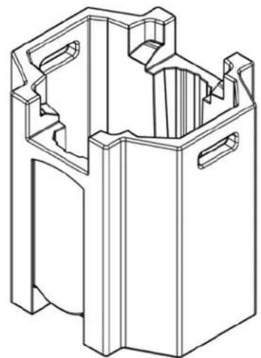
natural_image
Technical line drawing of a mechanical housing or enclosure component (no text or symbols)Specifications and improvements in the design of this unit and this manual are subject to change without any prior written notice.
OPTIONAL ACCESSORIES
| SKU (US) | SKU (EU) | DESCRIPTION |
| ESM166 | 1237000115 | Elation Smarty Max |
| TRIGGER CLAMP | 1741000032 | Heavy Duty Wrap Around Hook Style Clamp |
| AC5PDMX5PRO | N/A | 5 ft (1.5m) 5pin Pro DMX Cable |
| NEU088 | N/A | 3 ft (1m) Power Link Cable |
| ZB0MSDPLATINUM 400LFLEX | N/A | Philips MSD Platinum 400 Flex Lamp |
FCC STATEMENT
This device complies with Part 15 of the FCC Rules. Operation is subject to the following two conditions: (1) this device may not cause harmful interference, and (2) this device must accept any interference received, including interference that may cause undesired operation.
FCC RADIO FREQUENCY INTERFERENCE WARNINGS & INSTRUCTIONS
This product has been tested and found to comply with the limits as per Part 15 of the FCC Rules. These limits are designed to provide reasonable protection against harmful interference in a residential installation. This device uses and can radiate radio frequency energy and, if not installed and used in accordance with the included instructions, may cause harmful interference to radio communications. However, there is no guarantee that interference will not occur in a particular installation. If this device does cause harmful interference to radio or television reception, which can be determined by turning the device off and on, the user is encouraged to try to correct the interference by one or more of the following methods:
- Reorient or relocate the device.
- Increase the separation between the device and the receiver.
- Connect the device to an electrical outlet on a circuit different from which the radio receiver is connected.
- Consult the dealer or an experienced radio/TV technician for help.
Europe Energy Saving Notice
Energy Saving Matters (EuP 2009/125/EC)
Saving electric energy is a key to help protecting the environment. Please turn off all electrical products when they are not in use. To avoid power consumption in idle mode, disconnect all electrical equipment from power when not in use. Thank you

This page intentionally left blank.
- SMARTYMAX™
- DOCUMENT VERSION
- CONTENTS
- GENERAL INFORMATION
- INTRODUCTION
- UNPACKING
- BOX CONTENTS
- CUSTOMER SUPPORT
- LIMITED WARRANTY (USA ONLY)
- WARRANTY RETURNS
- SAFETY GUIDELINES
- PROTECTION CLASS 1 - FIXTURE MUST BE PROPERLY GROUNDED
- CAUTION
- DISCHARGE LAMP WARNING
- UV RADIATION NOTICE
- LAMP REPLACEMENT
- MAINTENANCE GUIDELINES
- DISCONNECT POWER BEFORE PERFORMING ANY MAINTENANCE!
- CLEANING
- MAINTENANCE
- FIXTURE OVERVIEW
- COLORS, GOBOS, ANIMATION
- INTERCHANGEABLE-ROTATING GLASS GOBO WHEEL 1
- STATIC-FIXED METAL GOBO WHEEL 2
- BI-DIRECTIONAL ANIMATION WHEEL
- GOBO SIZE
- \*\*\* IMPORTANT NOTICE REGARDING CUSTOM GOBOS \*\*\*
- GOBO REPLACEMENT
- REPLACING A ROTATING GOBO
- REPLACING A ROTATING GOBO
- LAMP PROTECTION CIRCUITRY
- LAMP LIFE OF PHILIPS PLATINUM 400L FLEX = UP TO 4,000 HOURS
- LAMP INSTALLATION PROCEDURE
- WARNING! LAMP REPLACEMENT SHOULD ONLY BE DONE BE A TRAINED TECHNICIAN.
- LAMP HOURS RESET PROCEDURE
- LAMP OPTIMIZATION
- FIXTURE INSTALLATION
- FLAMMABLE MATERIAL WARNING
- ELECTRICAL CONNECTIONS
- MINIMUM DISTANCE TO OBJECTS/SURFACES MUST BE 49.2 FEET (15 METERS)
- MINIMUM DISTANCE OF INFLAMMABLE MATERIALS FROM THE SURFACE 1.6 FEET (0.5 METER)
- MAXIMUM TEMP OF EXTERNAL SURFACE 248°F (120°C)
- DO NOT INSTALL THE FIXTURE IF YOU ARE NOT QUALIFIED TO DO SO!
- OMEGA BRACKETS INSTALLATION
- CLAMP INSTALLATION
- RIGGING
- ART-NET | sACN CONNECTION
- POTENTIAL INTERNAL FIXTURE DAMAGE FROM EXTERNAL SOURCES OF LIGHT BEAMS
- SUN PROTECTION MODE
- HIBERNATION MODE
- SYSTEM MENU
- PERSONALITY - Status Settings - Address Via DMX
- PERSONALITY - Service Setting - Password (050)
- PERSONALITY – Service Setting – USB Update
- ONLY QUALIFIED TECHNICIANS SHOULD PERFORM THIS FUNCTION! NOTE ALL MENU SETTINGS BEFORE UPDATING SOFTWARE! FIXTURE SOFTWARE CAN NOT BE DOWNGRADED! DOWNLOAD FIXTURE SOFTWARE TO PC ONLY! (NO MAC SUPPO PLEASE CONTACT ELATION SERVICE FOR FURTHER INFORMAT
- PERSONALITY - Display Setting – Key Lock
- PERSONALITY - Reset Default
- ONLY QUALIFIED TECHNICIANS SHOULD PERFORM THIS FUNCTION!
- EFFECT ADJUST – Test Channel
- EFFECT ADJUST – Manual Control
- EFFECT ADJUST – Calibration
- EDIT PROGRAM – Rec. Controller
- EDIT PROGRAM – Record Controller – Working with Built-In Programs
- EDIT PROGRAM – Record Controller – Working with Built-In Program [continued]
- Secondary Setting
- Automatic Program Run
- Program Selection for Auto Pro Part
- Program Selection for Edit Program
- Automatic Scene Recording
- Example:
- REMOTE DEVICE MANAGEMENT (RDM)
- SOFTWARE UPDATES
- E-LOADER III
- UPDATE/SERVICE PORT
- ERROR CODES
- SPECIFICATIONS
- SOURCE
- PHOTOMETRIC DATA
- Beam
- Spot
- Wash
- EFFECTS
- COLOR
- GOBOS
- CONTROL / CONNECTIONS
- SIZE / WEIGHT
- ELECTRICAL / THERMAL
- APPROVALS / RATINGS
- DIMENSIONAL DRAWINGS
- FCC STATEMENT
- FCC RADIO FREQUENCY INTERFERENCE WARNINGS & INSTRUCTIONS
Brand : Elation
Model : Smarty Max
Category : Machine à effets