
Pixel Bar 30IP - Machine à effets Elation - Free user manual and instructions
Find the device manual for free Pixel Bar 30IP Elation in PDF.


| Type of Product | LED Pixel Bar Effects Light |
| Model | Pixel Bar 30IP |
| Brand | Elation |
| Number of LEDs | 30 RGB LEDs |
| LED Power | 3 W per LED (90 W total) |
| Beam Angle | 12° |
| Control Protocols | DMX512, RDM |
| DMX Channels | 4, 5, 7, or 12 selectable |
| IP Rating | IP65 (weather-resistant) |
| Power Input | 100-240 V AC, 50/60 Hz |
| Power Consumption | 120 W |
| Dimensions (LxWxH) | 1000 x 100 x 150 mm |
| Weight | 5.2 kg |
| Housing Material | Aluminum with tempered glass lens |
| Mounting Options | Floor, truss, or wall mount with included brackets |
| Cooling | Convection (fanless) |
| Operating Temperature | -10°C to 45°C |
| Maintenance | Clean lens with soft cloth and mild detergent; check connections periodically |
| Safety Features | Overheat protection, safety cable attachment point |
| Replaceable Parts | LED module, power supply, DMX board (service by qualified technician) |
| Warranty | 2 years limited |
Frequently Asked Questions - Pixel Bar 30IP Elation
User questions about Pixel Bar 30IP Elation
0 question about this device. Answer the ones you know or ask your own.
Ask a new question about this device
Download the instructions for your Machine à effets in PDF format for free! Find your manual Pixel Bar 30IP - Elation and take your electronic device back in hand. On this page are published all the documents necessary for the use of your device. Pixel Bar 30IP by Elation.
USER MANUAL Pixel Bar 30IP Elation
natural_image
Pure architectural or engineering line drawing with no text, numbers, or symbolsPIXEL BAR
30IP™ / 60IP™ / 120IP™
user manual
©2021 ELATION PROFESSIONAL all rights reserved. Information, specifications, diagrams, images, and instructions herein are subject to change without notice. ELATION PROFESSIONAL logo and identifying product names and numbers herein are trademarks of ELATION PROFESSIONAL. Copyright protection claimed includes all forms and matters of copyrightable materials and information now allowed by statutory or judicial law or hereinafter granted. Product names used in this document may be trademarks or registered trademarks of their respective companies and are hereby acknowledged. All non-ELATION brands and product names are trademarks or registered trademarks of their respective companies.
ELATION PROFESSIONAL and all affiliated companies hereby disclaim all liabilities for property, equipment, building, and electrical damages, injuries to any persons, and direct or indirect economic loss associated with the use or reliance of any information contained within this document, and/or because of the improper, unsafe, insufficient and negligent assembly, installation, rigging, and operation of this product.
Elation Professional USA | 6122 S. Eastern Ave. | Los Angeles, CA. 90040 323-582-3322 | 323-832-9142 fax | www.elationlighting.com | info@elationlighting.com
Elation Professional B.V. | Junostraat 2 | 6468 EW Kerkrade, The Netherlands +31 45 546 85 66 | +31 45 546 85 96 fax | www.elationlighting.eu | info@elationlighting.eu
Elation Professional Mexico | AV Santa Ana 30 | Parque Industrial Lerma, Lerma, Mexico 52000 +52 (728) 282-7070
DOCUMENT VERSION

Due to additional product features and/or enhancements, an updated version of this document may be available online. Please scan the QR Code with your mobile device or visit www.elationlighting.com for the latest revision/update of this manual, before installation and/or programming.
| Date | Document Version | Notes |
| 05/23/18 | 1 | Initial release |
| 05/25/18 | 1.2 | Updated release |
| 06/08/18 | 1.4 | Added DMX Channel Chart |
| 11/27/18 | 1.6 | Updated version |
| 11/08/19 | 1.8 | Updated included power/data jumper cable spec (4pin not 5pin) |
| 11/08/21 | 2.0 | Add Cable Accessories |
CONTENTS
| General Information | 4 |
| Limited Warranty (USA Only) | 5 |
| Safety Guidelines | 6 |
| Maintenance Guidelines | 8 |
| Fixture Overview | 9 |
| Installation Guidelines | 10 |
| Connections and Cables | 14 |
| Linking and Control | 15 |
| DMX Channel Functions and Values | 16 |
| Specifications | 24 |
| Optional Accessories | 25 |
GENERAL INFORMATION
INTRODUCTION
This fixture has been designed to perform reliably for years when the information in this manual are followed. Please read and understand all the instructions and guidelines carefully and thoroughly before operating this unit. This manual contains important information regarding safety, installation, use, and maintenance.
UNPACKING
Each fixture has been thoroughly tested and shipped in perfect operating condition. Carefully check the outer shipping carton for signs of any damage that may have occurred during shipping. If the outer carton appears to be damaged, carefully inspect the fixture for damage and be sure all included accessories have arrived intact. In the event damage has been found and/or parts are missing, please contact our customer support team for further instructions. Please do NOT return this fixture to your dealer without first contacting customer support at the number listed below. Please do NOT discard the outer shipping carton in the trash. Please recycle whenever possible.
CUSTOMER SUPPORT
Contact ELATION Service for any product related service and support needs. Also visit forums.elationlighting.com with questions, comments or suggestions.
ELATION SERVICE USA - Monday - Friday 8:00am to 4:30pm PST 323-582-3322 | Fax 323-832-9142 | support@elationlighting.com
ELATION SERVICE EUROPE - Monday - Friday 08:30 to 17:00 CET +31 45 546 85 63 | Fax +31 45 546 85 96 | support@elationlighting.eu
REPLACEMENT PARTS please visit parts.elationlighting.com

IMPORTANT NOTICE!
THERE ARE NO USER SERVICEABLE PARTS INSIDE THIS UNIT. DO NOT ATTEMPT ANY REPAIRS YOURSELF; DOING SO WILL VOID YOUR MANUFACTURES WARRANTY. DAMAGES RESULTING FROM MODIFICATIONS TO THIS FIXTURE AND/OR THE DISREGARD OF SAFETY INSTRUCTIONS AND GUIDELINES IN THIS MANUAL VOID THE MANUFACTURES WARRANTY AND ARE NOT SUBJECT TO ANY WARRANTY CLAIMS AND/OR REPAIRS.
LIMITED WARRANTY (USA ONLY)
A. Elation Professional hereby warrants, to the original purchaser, Elation Professional products to be free of manufacturing defects in material and workmanship for a period of two years (730 days), and Elation Professional product rechargeable batteries to be free of manufacturing defects in material and workmanship for a period of six months (180 days), from the original date of purchase. This warranty excludes discharge lamps and all product accessories. This warranty shall be valid only if the product is purchased within the United States of America, including possessions and territories. It is the owner's responsibility to establish the date and place of purchase by acceptable evidence, at the time service is sought.
B. For warranty service, send the product only to the Elation Professional factory. All shipping charges must be pre-paid. If the requested repairs or service (including parts replacement) are within the terms of this warranty, Elation Professional will pay return shipping charges only to a designated point within the United States. If any product is sent, it must be shipped in its original package and packaging material. No accessories should be shipped with the product. If any accessories are shipped with the product, Elation Professional shall have no liability what-so-ever for loss and/or damage to any such accessories, nor for the safe return thereof.
C. This warranty is void if the product serial number and/or labels are altered or removed; if the product is modified in any manner which Elation Professional concludes, after inspection, affects the reliability of the product; if the product has been repaired or serviced by anyone other than the Elation Professional factory unless prior written authorization was issued to purchaser by Elation Professional; if the product is damaged because not properly maintained as set forth in the product instructions, guidelines and/or user manual.
D. This is not a service contract, and this warranty does not include any maintenance, cleaning, or periodic check-up. During the periods as specified above, Elation Professional will replace defective parts at its expense, and will absorb all expenses for warranty service and repair labor by reason of defects in material or workmanship. The sole responsibility of Elation Professional under this warranty shall be limited to the repair of the product, or replacement thereof, including parts, at the sole discretion of Elation Professional. All products covered by this warranty were manufactured after January 1, 1990, and bare identifying marks to that effect.
E. Elation Professional reserves the right to make changes in design and/or performance improvements upon its products without any obligation to include these changes in any products theretofore manufactured.
F. No warranty, whether expressed or implied, is given or made with respect to any accessory supplied with the products described above. Except to the extent prohibited by applicable law, all implied warranties made by Elation Professional in connection with this product, including warranties of merchantability or fitness, are limited in duration to the warranty periods set forth above. And no warranties, whether expressed or implied, including warranties of merchantability or fitness, shall apply to this product after said periods have expired. The consumer's and/or dealer's sole remedy shall be such repair or replacement as is expressly provided above; and under no circumstances shall Elation Professional be liable for any loss and/or damage, direct and/or consequential, arising out of the use of, and/or the inability to use, this product.
G. This warranty is the only written warranty applicable to Elation Professional products and supersedes all prior warranties and written descriptions of warranty terms and conditions heretofore published.
WARRANTY RETURNS
All returned service items whether under warranty or not, must be freight pre-paid and accompany a return authorization (R.A.) number. The R.A. number must be clearly written on the outside of the return package. A brief description of the problem as well as the R.A. number must also be written down on a piece of paper and included in the shipping container. If the unit is under warranty, you must provide a copy of your proof of purchase invoice. Items returned without a R.A. number clearly marked on the outside of the package will be refused and returned at customer's expense. You may obtain a R.A. number by contacting customer support.
SAFETY GUIDELINES
To guarantee a smooth operation, it is important to follow all instructions and guidelines in this manual. Elation Professional is not responsible for injury and/or damages resulting from the misuse of this fixture due to the disregard of the information printed in this manual. Only qualified and/or certified personnel should perform installation of this fixture and only the original rigging parts included with this fixture should be used for installation. Any modifications to the fixture and/or the included mounting hardware will void the original manufactures warranty and increase the risk of damage and/or personal injury.
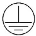
PROTECTION CLASS 1 - FIXTURE MUST BE PROPERLY GROUNDED

THERE ARE NO USER SERVICEABLE PARTS INSIDE THIS UNIT. DO NOT ATTEMPT ANY REPAIRS YOURSELF; DOING SO WILL VOID YOU MANUFACTURES WARRANTY. DAMAGES RESULTING FROM MODIFICATIONS TO THIS FIXTURE AND/OR THE DISREGARD OF SAFETY INSTRUCTIONS AND GUIDELINES IN THIS MANUAL VOID THE MANUFACTURES WARRANTY AND ARE NOT SUBJECT TO ANY WARRANTY CLAIMS AND/OR REPAIRS.

DO NOT PLUG FIXTURE INTO A DIMMER PACK! NEVER OPEN THIS FIXTURE WHILE IN USE! UNPLUG POWER BEFORE SERVICING FIXTURE! NEVER TOUCH FIXTURE DURING OPERATION, AS IT MAY BE HOT! KEEP FLAMMABLE MATERIALS AWAY FROM FIXTURE!

ENSURE ALL CONNECTIONS AND END CAPS ARE PROPERLY SEALED WITH A DIELECTRIC GREASE (AVAILABLE AT MOST ELECTRICAL SUPPLIERS) TO PREVENT WATER CORROSION AND/OR ELECTRICAL SHORT CIRCUIT.
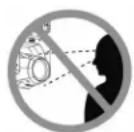
NEVER LOOK DIRECTLY INTO THE LIGHT SOURCE! RETINA INJURY RISK - MAY INDUCE BLINDNESS! SENSITIVE PERSONS MAY SUFFER AN EPILEPTIC SHOCK!
SAFETY GUIDELINES
DO NOT TOUCH the fixture housing during operation. Turn OFF the power and allow approximately 15 minutes for the fixture to cool down before serving.
DO NOT shake fixture, avoid brute force when installing and/or operating fixture.
DO NOT operate fixture if the power/data cables are frayed, crimped, damaged and/or if any of the connectors are damaged and do not insert into the fixture securely with ease. NEVER force a power/data cable connector into the fixture. If the power/data cable or any of its connectors are damaged, replace it immediately with a new one.
DO NOT block the air value on the bottom of the fixture.
This must remain clean and never blocked.
When installing fixture in a suspended environment, always use mounting hardware that is no less than M10 x 25 mm, and always install fixture with an appropriately rated safety cable.
ALWAYS disconnect fixture from main power source before performing any type of service and/or cleaning procedure.
NEVER pull out the power/data cable by tugging the wire portion of the cable.
Consistent operational breaks will ensure the fixture will function properly for many years.
ONLY Use the original packaging and materials to transport the fixture in for service.
MAINTENANCE GUIDELINES

DISCONNECT POWER BEFORE PERFORMING ANY MAINTENANCE!
CLEANING
Frequent cleaning is recommended to insure proper function, optimized light output, and an extended life. The frequency of cleaning depends on the environment in which the fixture operates: damp, smoky or particularly dirty environments can cause greater accumulation of dirt on the fixture's optics. Clean the external lens surface at least every 20 days with a soft cloth to avoid dirt/debris accumulation.
NEVER use alcohol, solvents, or ammonia-based cleaners.
MAINTENANCE
Regular inspections are recommended to insure proper function and extended life.
There are no user serviceable parts inside this fixture, please refer all other service issues to an authorized Elation service technician. Should you need any spare parts, please order genuine parts from your local Elation dealer.
Please refer to the following points during routine inspections:
A detailed electric check by an approved electrical engineer every three months to make sure the circuit contacts are in good condition and prevent overheating.
Be sure all screws, fasteners, and clamp bolts are securely tightened at all times. Lose screws may fall out during normal operation resulting in damage or injury as larger parts could fall.
Check for any deformations on the housing, lens covers, rigging hardware and rigging points (ceiling, suspension, trussing). Deformations in the housing could allow for dust to enter into the fixture.
Damaged rigging points or unsecured rigging could cause the fixture to fall and seriously injure a person(s).
Power/data cables must not show any damage, material fatigue or sediments.
FIXTURE OVERVIEW

- Magnetic End Cap
- Power/Data INPUT (see Optional Accessories for cable part numbers)
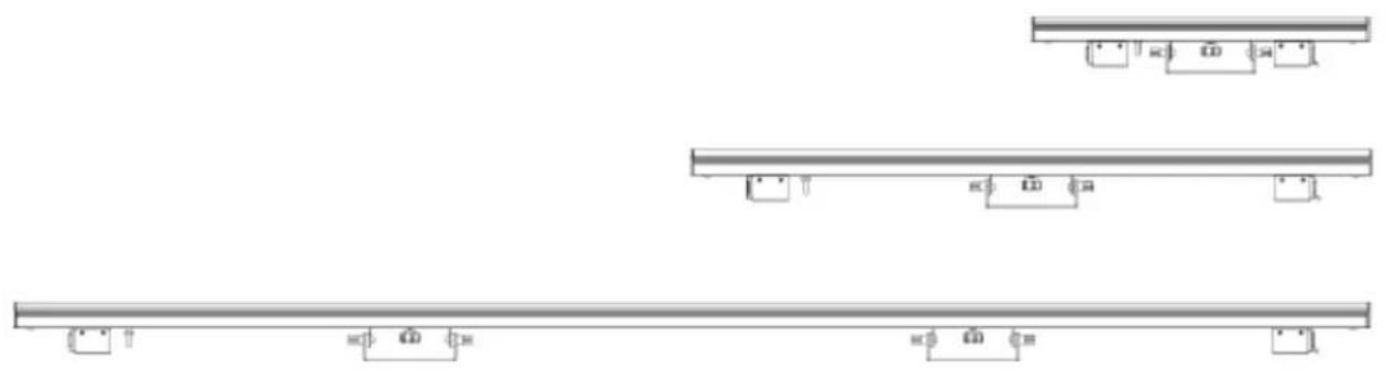
- Sliding Position Adjustable 3-Hole Mounting Yoke (Pixel Bar 120IP includes 2)
- Safety Cable Attachment Loop
- Power/Data OUTPUT (see Optional Accessories for cable part numbers)
- Magnetic End Cap
INCLUDED ITEMS
PIXEL BAR IP
2 ft (0.6m) 4pin 16AWG Power/Data Jumper Cable
Frosted Square Lens Cover
Frosted Round Lens Cover
INSTALLATION GUIDELINES
IP65 RATED
An IP rated lighting fixture is one, which is commonly installed in outdoor environments and has been designed with an enclosure that effectively protects the ingress (entry) of external foreign objects such as dust and water. The International Protection (IP) rating system is commonly expressed as "IP" (Ingress Protection) followed by two numbers (i.e. IP65) where the numbers define the degree of protection. The first digit (Foreign Bodies Protection) indicates the extent of protection against particles entering the fixture and the second digit (Water Protection) indicates the extent of protection against water entering the fixture. An IP65 rated lighting fixture is one, which has been designed and tested to protect against the ingress of dust (6) and high-pressure water jets from any direction (5).
MARINE/COASTAL ENVIRONMENT INSTALLATIONS
Please note although this fixture is IP rated, the fixture is NOT suitable for marine and/or coastal environment installations. Installing this fixture in a marine and/or coastal environment may cause corrosion and/or excessive wear to the interior and/or exterior components of the fixture. Damages and/or performance issues resulting from installation in a marine and/or coastal environment will void the manufactures warranty and will NOT be subject to any warranty claims and/or repairs.
OPTIONAL CORROSION-RESISTANT COATING
Optional Corrosion-Resistant Coatings may be available for this fixture.
Please contact Elation Professional for more details.

FLAMMABLE MATERIAL WARNING
Keep fixture minimum 5.0 feet (1.5m) away from flammable materials and/or pyrotechnics.

ELECTRICAL CONNECTIONS
A qualified electrician should be used for all electrical connections and/or installations.

ENSURE ALL CONNECTIONS AND END CAPS ARE PROPERLY SEALED WITH A NON-CONDUCTIVE DIELECTRIC GREASE (AVAILABLE AT MOST ELECTRICAL SUPPLIERS) TO PREVENT WATER INGRESS/CONDENSATION AND/OR CORROSION.

TO MAINTAIN IP65 RATING INTEGRITY AND PREVENT WATER FROM ENTERING THE FIXTURE, ALL UNUSED CONNECTION RUBBER CAPS MUST BE INSERTED/SEALED.
INSTALLATION GUIDELINES

DO NOT INSTALL THE FIXTURE IF YOU ARE NOT QUALIFIED TO DO SO!
Fixture MUST be installed following all local, national, and country commercial electrical and construction codes and regulations.
Before rigging/mounting a single fixture or multiple interconnected fixtures for custom matrix designs to any metal truss/structure or placing the fixture(s) on any surface, a professional equipment installer MUST be consulted to determine if the metal truss/structure or surface is properly certified to safely hold the combined weight of the fixture(s), clamps, cables, and accessories.
Fixture ambient operating temperature range is 14^ to 113^ F. ( -10^ to 45^ C)
Do not use the fixture under or above this temperature.
Fixture(s) should be installed in areas outside walking paths, seating areas, or away from areas were unauthorized personnel might reach the fixture by hand.
NEVER stand directly below the fixture(s) when rigging, removing or servicing.
Overhead fixture installation must always be secured with a secondary safety attachment, such as an appropriately rated safety cable that meets all local, national, and country codes and regulations. Allow approximately 15 minutes for the fixture to cool down before serving.
MOUNTING YOKE
This fixture includes an adjustable sliding position mounting yoke and safety cable rigging point attached to the fixture. (see the illustration below) (Pixel Bar 120IP includes 2 yokes)
To adjust the mounting yoke to a desired position, loosen thumb screw, move the yoke to the desired position, then tighten the thumb screw securely.
DO NOT OVER TIGHTEN THE THUMB SCREW!

flowchart
graph LR
    A["Component 1"] <--> B["Component 2"]
    B <--> C["Component 3"]
    C <--> D["Component 4"]
SURFACE MOUNTING
The fixture can be mounted to a flat surface via the mounting yoke using appropriate mounting hardware (not included). Use careful planning when surface mounting fixtures to allow ample space for power/data cables.
TRUSS MOUNTING
The fixture can be attached to truss or a like structure via the mounting yoke using an appropriated truss clamp (not included) and an M10 screw (not included).
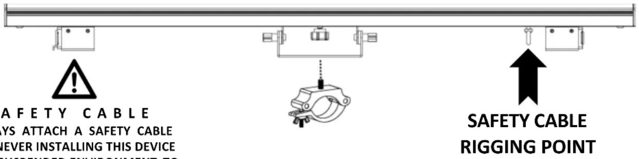
SAFETY CABLE ALWAYS ATTACH A SAFETY CABLE WHENEVER INSTALLING THIS DEVICE IN A SUSPENDED ENVIRONMENT TO ENSURE THE FIXTURE WILL NOT DROP IF THE CLAMP FAILS.
RIGGING
Overhead rigging requires extensive experience, including amongst others calculating working load limits, installation material being used, and periodic safety inspection of all installation material and the fixture. If you lack these qualifications, do not attempt the installation yourself. Improper installation can result in bodily injury.

INSTALLATION LOCATION PLANNING
Use careful planning to select installation locations of PIXEL BAR IP unit(s). The maximum distance from the PIXEL DRIVER 4000 to the first pixel bar can NOT exceed 50 feet (18m).
END-TO-END ALIGNMENT
The fixture includes magnetic end caps on both sides which allows seamless end-to-end linear alignment of multiple units. (see image below) Each fixture MUST be securely attached/installed using one of the methods mentioned above.
THIS FEATURE IS FOR ALIGNMENT PURPOSES ONLY!

natural_image
Technical line drawing showing two mechanical assembly steps with no visible text or symbolsDIFFUSER LENS COVERS
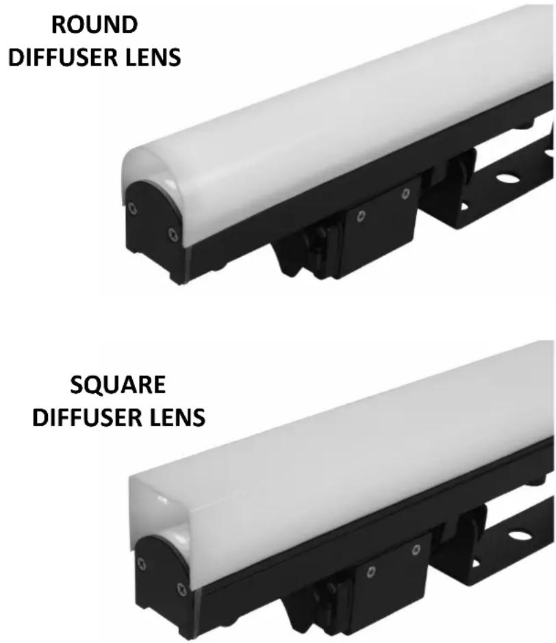
Square and rounded edge diffuser lens covers are included. These can be attached to the fixture by aligning the lens to the grooves on both sides of the fixture, starting on one end of the fixture and then carefully sliding the lens over the length of the top cover.
It is best to attach the frosted lens covers before mounting the fixture.

FOR OVERHEAD RIGGING INSTALLATIONS, IT IS SUGGESTED TO APPLY SMALL BEADS OF SILCONE GLUE ALONG BOTH SIDES OF THE DIFFUSER LENS AND FIXTURE TO PREVENT THE POSSIBILITY OF THE LENS DETACHING/FALLING!
CONNECTIONS AND CABLES
CONNECTIONS
The fixture features IP65 rated 4pin power/data combination input and output connections.
The wiring diagram below provides the pin details.

TO MAINTAIN IP65 RATING INTEGRITY AND PREVENT WATER FROM ENTERING THE FIXTURE, ALL UNUSED CONNECTION RUBBER CAPS MUST BE INSERTED/SEALED.

ENSURE ALL CONNECTIONS AND END CAPS ARE PROPERLY SEALED WITH A DIELECTRIC GREASE (AVAILABLE AT MOST ELECTRICAL SUPPLIERS) TO PREVENT WATER CORROSION AND/OR ELECTRICAL SHORT CIRCUIT.
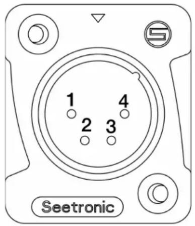
PIN #1 - (+) Power
PIN #2 - Data
PIN #3 - CLK (clock pin)
PIN #4 - (-) Power
CABLES
ELATION P BAR IP 4pin 16AWG power/data cables are available in various lengths.
See Optional Accessories for details.

MAXIMUM CABLE DISTANCES - 16AWG
The following maximum cable distances apply when using 16AWG cables.
PIXEL DRIVER 4000 to 1 ^st PIXEL BAR IP = Maximum 50 feet (18 meters)
PIXEL BAR IP to PIXEL BAR IP = Maximum 32 feet (10 meters)
Total combined length of cables can NOT exceed = Maximum 98 feet (30 meters)

MAXIMUM CABLE DISTANCES - 12AWG
The following maximum cable distances apply when using 12AWG cables.
PIXEL DRIVER 4000 to 1 ^st PIXEL BAR IP = Maximum 50 feet (18 meters)
PIXEL BAR IP to PIXEL BAR IP = Maximum 32 feet (10 meters)
Total combined length of cables can NOT exceed = Maximum 213 feet (65 meters)
LINKING AND CONTROL
LINKING
Maximum pixels/bars each PIXEL DRIVER 4000™ supports is listed in charts below.
Multiple combinations of PIXEL BAR IP models can be linked (daisy-chained) together to a single driver port, providing the maximum number of pixels/bars is NOT exceeded.
KLING-NET = 1,020 Max Pixels per PIXEL DRIVER 4000 Port
Art-NET/sACN = 170 Max Pixels per PIXEL DRIVER 4000 Port
| MODEL | TOTAL PIXELS | TOTAL CONTROL CHANNELS | KLING-NET1,020 Max Pixels per Driver Port4,080 Max Pixels per Driver Unit | |||
| MAX BARS per DRIVER PORT | MAX PIXELS per DRIVER PORT | MAX BARS per DRIVER UNIT | MAX PIXELS per DRIVER UNIT | |||
| PIXEL BAR 30IP | 30 | 90 | 34 | 1020 | 136 | 4080 |
| PIXEL BAR 60IP | 60 | 180 | 17 | 1020 | 68 | 4080 |
| PIXEL BAR 120IP | 120 | 360 | 8 | 960 | 32 | 3840 |
| MODEL | TOTAL PIXELS | TOTAL CONTROL CHANNELS | ART-NET/sACN170 Max Pixels per Driver Port680 Max Pixels per Driver Unit | |||
| MAX BARS per DRIVER PORT | MAX PIXELS per DRIVER PORT | MAX BARS per DRIVER UNIT | MAX PIXELS per DRIVER UNIT | |||
| PIXEL BAR 30IP | 30 | 90 | 5 | 150 | 20 | 600 |
| PIXEL BAR 60IP | 60 | 180 | 2 | 120 | 8 | 480 |
| PIXEL BAR 120IP | 120 | 360 | 1 | 120 | 4 | 480 |
CONTROL
The PIXEL DRIVER 4000 (sold separately) which supports Kling-NET, Art-NET, and sACN protocols, controls the PIXEL BAR IPs. (see PIXEL DRIVER 4000 manual for details)
DMX CHANNEL FUNCTIONS AND VALUES
| ELATION PIXEL BAR 30IP / 60IP / 120IPDMX Channel Values / Functions (90 / 180 / 360 DMX Channels) | ||||
| PIXEL BAR 30IP | PIXEL BAR 60IP | PIXEL BAR 120IP | VALUE | FUNCTION |
| 1 | 1 | 1 | 0-255 | RED |
| 2 | 2 | 2 | 0-255 | GREEN |
| 3 | 3 | 3 | 0-255 | BLUE |
| 4 | 4 | 4 | 0-255 | RED |
| 5 | 5 | 5 | 0-255 | GREEN |
| 6 | 6 | 6 | 0-255 | BLUE |
| 7 | 7 | 7 | 0-255 | RED |
| 8 | 8 | 8 | 0-255 | GREEN |
| 9 | 9 | 9 | 0-255 | BLUE |
| 10 | 10 | 10 | 0-255 | RED |
| 11 | 11 | 11 | 0-255 | GREEN |
| 12 | 12 | 12 | 0-255 | BLUE |
| 13 | 13 | 13 | 0-255 | RED |
| 14 | 14 | 14 | 0-255 | GREEN |
| 15 | 15 | 15 | 0-255 | BLUE |
| 16 | 16 | 16 | 0-255 | RED |
| 17 | 17 | 17 | 0-255 | GREEN |
| 18 | 18 | 18 | 0-255 | BLUE |
| 19 | 19 | 19 | 0-255 | RED |
| 20 | 20 | 20 | 0-255 | GREEN |
| 21 | 21 | 21 | 0-255 | BLUE |
| 22 | 22 | 22 | 0-255 | RED |
| 23 | 23 | 23 | 0-255 | GREEN |
| 24 | 24 | 24 | 0-255 | BLUE |
| 25 | 25 | 25 | 0-255 | RED |
| 26 | 26 | 26 | 0-255 | GREEN |
| 27 | 27 | 27 | 0-255 | BLUE |
| 28 | 28 | 28 | 0-255 | RED |
| 29 | 29 | 29 | 0-255 | GREEN |
| 30 | 30 | 30 | 0-255 | BLUE |
| 31 | 31 | 31 | 0-255 | RED |
| 32 | 32 | 32 | 0-255 | GREEN |
| 33 | 33 | 33 | 0-255 | BLUE |
| 34 | 34 | 34 | 0-255 | RED |
| 36 | 35 | 35 | 0-255 | GREEN |
| 36 | 36 | 36 | 0-255 | BLUE |
| 37 | 37 | 37 | 0-255 | RED |
| 38 | 38 | 38 | 0-255 | GREEN |
| 39 | 39 | 39 | 0-255 | BLUE |
| 40 | 40 | 40 | 0-255 | RED |
| 41 | 41 | 41 | 0-255 | GREEN |
| 42 | 42 | 42 | 0-255 | BLUE |
| 43 | 43 | 43 | 0-255 | RED |
| 44 | 44 | 44 | 0-255 | GREEN |
| 45 | 45 | 45 | 0-255 | BLUE |
| PIXEL BAR 30IP | PIXEL BAR 60IP | PIXEL BAR 120IP | VALUE | FUNCTION |
| 46 | 46 | 46 | 0-255 | RED |
| 47 | 47 | 47 | 0-255 | GREEN |
| 48 | 48 | 48 | 0-255 | BLUE |
| 49 | 49 | 49 | 0-255 | RED |
| 50 | 50 | 50 | 0-255 | GREEN |
| 51 | 51 | 51 | 0-255 | BLUE |
| 52 | 52 | 52 | 0-255 | RED |
| 53 | 53 | 53 | 0-255 | GREEN |
| 54 | 54 | 54 | 0-255 | BLUE |
| 55 | 55 | 55 | 0-255 | RED |
| 56 | 56 | 56 | 0-255 | GREEN |
| 57 | 57 | 57 | 0-255 | BLUE |
| 58 | 58 | 58 | 0-255 | RED |
| 59 | 59 | 59 | 0-255 | GREEN |
| 60 | 60 | 60 | 0-255 | BLUE |
| 61 | 61 | 61 | 0-255 | RED |
| 62 | 62 | 62 | 0-255 | GREEN |
| 63 | 63 | 63 | 0-255 | BLUE |
| 64 | 64 | 64 | 0-255 | RED |
| 65 | 65 | 65 | 0-255 | GREEN |
| 66 | 66 | 66 | 0-255 | BLUE |
| 67 | 67 | 67 | 0-255 | RED |
| 68 | 68 | 68 | 0-255 | GREEN |
| 69 | 69 | 69 | 0-255 | BLUE |
| 70 | 70 | 70 | 0-255 | RED |
| 71 | 71 | 71 | 0-255 | GREEN |
| 72 | 72 | 72 | 0-255 | BLUE |
| 73 | 73 | 73 | 0-255 | RED |
| 74 | 74 | 74 | 0-255 | GREEN |
| 75 | 75 | 75 | 0-255 | BLUE |
| 76 | 76 | 76 | 0-255 | RED |
| 77 | 77 | 77 | 0-255 | GREEN |
| 78 | 78 | 78 | 0-255 | BLUE |
| 79 | 79 | 79 | 0-255 | RED |
| 80 | 80 | 80 | 0-255 | GREEN |
| 81 | 81 | 81 | 0-255 | BLUE |
| 82 | 82 | 82 | 0-255 | RED |
| 83 | 83 | 83 | 0-255 | GREEN |
| 84 | 84 | 84 | 0-255 | BLUE |
| 85 | 85 | 85 | 0-255 | RED |
| 86 | 86 | 86 | 0-255 | GREEN |
| 87 | 87 | 87 | 0-255 | BLUE |
| 88 | 88 | 88 | 0-255 | RED |
| 89 | 89 | 89 | 0-255 | GREEN |
| 90 | 90 | 90 | 0-255 | BLUE |
| PIXEL BAR 60IP | PIXEL BAR 120IP | VALUE | FUNCTION |
| 91 | 91 | 0-255 | RED |
| 92 | 92 | 0-255 | GREEN |
| 93 | 93 | 0-255 | BLUE |
| 94 | 94 | 0-255 | RED |
| 95 | 95 | 0-255 | GREEN |
| 96 | 96 | 0-255 | BLUE |
| 97 | 97 | 0-255 | RED |
| 98 | 98 | 0-255 | GREEN |
| 99 | 99 | 0-255 | BLUE |
| 100 | 100 | 0-255 | RED |
| 101 | 101 | 0-255 | GREEN |
| 102 | 102 | 0-255 | BLUE |
| 103 | 103 | 0-255 | RED |
| 104 | 104 | 0-255 | GREEN |
| 105 | 105 | 0-255 | BLUE |
| 106 | 106 | 0-255 | RED |
| 107 | 107 | 0-255 | GREEN |
| 108 | 108 | 0-255 | BLUE |
| 109 | 109 | 0-255 | RED |
| 110 | 110 | 0-255 | GREEN |
| 111 | 111 | 0-255 | BLUE |
| 112 | 112 | 0-255 | RED |
| 113 | 113 | 0-255 | GREEN |
| 114 | 114 | 0-255 | BLUE |
| 115 | 115 | 0-255 | RED |
| 116 | 116 | 0-255 | GREEN |
| 117 | 117 | 0-255 | BLUE |
| 118 | 118 | 0-255 | RED |
| 119 | 119 | 0-255 | GREEN |
| 120 | 120 | 0-255 | BLUE |
| 121 | 121 | 0-255 | RED |
| 122 | 122 | 0-255 | GREEN |
| 123 | 123 | 0-255 | BLUE |
| 124 | 124 | 0-255 | RED |
| 125 | 125 | 0-255 | GREEN |
| 126 | 126 | 0-255 | BLUE |
| 127 | 127 | 0-255 | RED |
| 128 | 128 | 0-255 | GREEN |
| 129 | 129 | 0-255 | BLUE |
| 130 | 130 | 0-255 | RED |
| 131 | 131 | 0-255 | GREEN |
| 132 | 132 | 0-255 | BLUE |
| 133 | 133 | 0-255 | RED |
| 134 | 134 | 0-255 | GREEN |
| 135 | 135 | 0-255 | BLUE |
| 136 | 136 | 0-255 | RED |
| 137 | 137 | 0-255 | GREEN |
| 138 | 138 | 0-255 | BLUE |
| 139 | 139 | 0-255 | RED |
| 140 | 140 | 0-255 | GREEN |
| 141 | 141 | 0-255 | BLUE |
| 142 | 142 | 0-255 | RED |
| 143 | 143 | 0-255 | GREEN |
| 144 | 144 | 0-255 | BLUE |
| 145 | 145 | 0-255 | RED |
| 146 | 146 | 0-255 | GREEN |
| 147 | 147 | 0-255 | BLUE |
| 148 | 148 | 0-255 | RED |
| 149 | 149 | 0-255 | GREEN |
| 150 | 150 | 0-255 | BLUE |
| 151 | 151 | 0-255 | RED |
| 152 | 152 | 0-255 | GREEN |
| 153 | 153 | 0-255 | BLUE |
| 154 | 154 | 0-255 | RED |
| 155 | 155 | 0-255 | GREEN |
| 156 | 156 | 0-255 | BLUE |
| 157 | 157 | 0-255 | RED |
| 158 | 158 | 0-255 | GREEN |
| 159 | 159 | 0-255 | BLUE |
| 160 | 160 | 0-255 | RED |
| 161 | 161 | 0-255 | GREEN |
| 162 | 162 | 0-255 | BLUE |
| 163 | 163 | 0-255 | RED |
| 164 | 164 | 0-255 | GREEN |
| 165 | 165 | 0-255 | BLUE |
| 166 | 166 | 0-255 | RED |
| 167 | 167 | 0-255 | GREEN |
| 168 | 168 | 0-255 | BLUE |
| 169 | 169 | 0-255 | RED |
| 170 | 170 | 0-255 | GREEN |
| 171 | 171 | 0-255 | BLUE |
| 172 | 172 | 0-255 | RED |
| 173 | 173 | 0-255 | GREEN |
| 174 | 174 | 0-255 | BLUE |
| 175 | 175 | 0-255 | RED |
| 176 | 176 | 0-255 | GREEN |
| 177 | 177 | 0-255 | BLUE |
| 178 | 178 | 0-255 | RED |
| 179 | 179 | 0-255 | GREEN |
| 180 | 180 | 0-255 | BLUE |
| PIXEL BAR 120IP | VALUE | FUNCTION |
| 181 | 0-255 | RED |
| 182 | 0-255 | GREEN |
| 183 | 0-255 | BLUE |
| 184 | 0-255 | RED |
| 185 | 0-255 | GREEN |
| 186 | 0-255 | BLUE |
| 187 | 0-255 | RED |
| 188 | 0-255 | GREEN |
| 189 | 0-255 | BLUE |
| 190 | 0-255 | RED |
| 191 | 0-255 | GREEN |
| 192 | 0-255 | BLUE |
| 193 | 0-255 | RED |
| 194 | 0-255 | GREEN |
| 195 | 0-255 | BLUE |
| 196 | 0-255 | RED |
| 197 | 0-255 | GREEN |
| 198 | 0-255 | BLUE |
| 199 | 0-255 | RED |
| 200 | 0-255 | GREEN |
| 201 | 0-255 | BLUE |
| 202 | 0-255 | RED |
| 203 | 0-255 | GREEN |
| 204 | 0-255 | BLUE |
| 205 | 0-255 | RED |
| 206 | 0-255 | GREEN |
| 207 | 0-255 | BLUE |
| 208 | 0-255 | RED |
| 209 | 0-255 | GREEN |
| 210 | 0-255 | BLUE |
| 211 | 0-255 | RED |
| 212 | 0-255 | GREEN |
| 213 | 0-255 | BLUE |
| 214 | 0-255 | RED |
| 215 | 0-255 | GREEN |
| 216 | 0-255 | BLUE |
| 217 | 0-255 | RED |
| 218 | 0-255 | GREEN |
| 219 | 0-255 | BLUE |
| 220 | 0-255 | RED |
| 221 | 0-255 | GREEN |
| 222 | 0-255 | BLUE |
| 223 | 0-255 | RED |
| 224 | 0-255 | GREEN |
| 225 | 0-255 | BLUE |
| 226 | 0-255 | RED |
| 227 | 0-255 | GREEN |
| 228 | 0-255 | BLUE |
| 229 | 0-255 | RED |
| 230 | 0-255 | GREEN |
| 231 | 0-255 | BLUE |
| 232 | 0-255 | RED |
| 233 | 0-255 | GREEN |
| 234 | 0-255 | BLUE |
| 235 | 0-255 | RED |
| 236 | 0-255 | GREEN |
| 237 | 0-255 | BLUE |
| 238 | 0-255 | RED |
| 239 | 0-255 | GREEN |
| 240 | 0-255 | BLUE |
| 241 | 0-255 | RED |
| 242 | 0-255 | GREEN |
| 243 | 0-255 | BLUE |
| 244 | 0-255 | RED |
| 245 | 0-255 | GREEN |
| 246 | 0-255 | BLUE |
| 247 | 0-255 | RED |
| 248 | 0-255 | GREEN |
| 249 | 0-255 | BLUE |
| 250 | 0-255 | RED |
| 251 | 0-255 | GREEN |
| 252 | 0-255 | BLUE |
| 253 | 0-255 | RED |
| 254 | 0-255 | GREEN |
| 255 | 0-255 | BLUE |
| 256 | 0-255 | RED |
| 257 | 0-255 | GREEN |
| 258 | 0-255 | BLUE |
| 259 | 0-255 | RED |
| 260 | 0-255 | GREEN |
| 261 | 0-255 | BLUE |
| 262 | 0-255 | RED |
| 263 | 0-255 | GREEN |
| 264 | 0-255 | BLUE |
| 265 | 0-255 | RED |
| 266 | 0-255 | GREEN |
| 267 | 0-255 | BLUE |
| 268 | 0-255 | RED |
| 269 | 0-255 | GREEN |
| 270 | 0-255 | BLUE |
| 271 | 0-255 | RED |
| 272 | 0-255 | GREEN |
| 273 | 0-255 | BLUE |
| 274 | 0-255 | RED |
| 275 | 0-255 | GREEN |
| 276 | 0-255 | BLUE |
| 277 | 0-255 | RED |
| 278 | 0-255 | GREEN |
| 279 | 0-255 | BLUE |
| 280 | 0-255 | RED |
| 281 | 0-255 | GREEN |
| 282 | 0-255 | BLUE |
| 283 | 0-255 | RED |
| 284 | 0-255 | GREEN |
| 285 | 0-255 | BLUE |
| 286 | 0-255 | RED |
| 287 | 0-255 | GREEN |
| 288 | 0-255 | BLUE |
| 289 | 0-255 | RED |
| 290 | 0-255 | GREEN |
| 291 | 0-255 | BLUE |
| 292 | 0-255 | RED |
| 293 | 0-255 | GREEN |
| 294 | 0-255 | BLUE |
| 295 | 0-255 | RED |
| 296 | 0-255 | GREEN |
| 297 | 0-255 | BLUE |
| 298 | 0-255 | RED |
| 299 | 0-255 | GREEN |
| 300 | 0-255 | BLUE |
| 301 | 0-255 | RED |
| 302 | 0-255 | GREEN |
| 303 | 0-255 | BLUE |
| 304 | 0-255 | RED |
| 305 | 0-255 | GREEN |
| 306 | 0-255 | BLUE |
| 307 | 0-255 | RED |
| 308 | 0-255 | GREEN |
| 309 | 0-255 | BLUE |
| 310 | 0-255 | RED |
| 311 | 0-255 | GREEN |
| 312 | 0-255 | BLUE |
| 313 | 0-255 | RED |
| 314 | 0-255 | GREEN |
| 315 | 0-255 | BLUE |
| 316 | 0-255 | RED |
| 317 | 0-255 | GREEN |
| 318 | 0-255 | BLUE |
| 319 | 0-255 | RED |
| 320 | 0-255 | GREEN |
| 321 | 0-255 | BLUE |
| 322 | 0-255 | RED |
| 323 | 0-255 | GREEN |
| 324 | 0-255 | BLUE |
| 325 | 0-255 | RED |
| 326 | 0-255 | GREEN |
| 327 | 0-255 | BLUE |
| 328 | 0-255 | RED |
| 329 | 0-255 | GREEN |
| 330 | 0-255 | BLUE |
| 331 | 0-255 | RED |
| 332 | 0-255 | GREEN |
| 333 | 0-255 | BLUE |
| 334 | 0-255 | RED |
| 335 | 0-255 | GREEN |
| 336 | 0-255 | BLUE |
| 337 | 0-255 | RED |
| 338 | 0-255 | GREEN |
| 339 | 0-255 | BLUE |
| 340 | 0-255 | RED |
| 341 | 0-255 | GREEN |
| 342 | 0-255 | BLUE |
| 343 | 0-255 | RED |
| 344 | 0-255 | GREEN |
| 345 | 0-255 | BLUE |
| 346 | 0-255 | RED |
| 347 | 0-255 | GREEN |
| 348 | 0-255 | BLUE |
| 349 | 0-255 | RED |
| 350 | 0-255 | GREEN |
| 351 | 0-255 | BLUE |
| 352 | 0-255 | RED |
| 353 | 0-255 | GREEN |
| 354 | 0-255 | BLUE |
| 355 | 0-255 | RED |
| 356 | 0-255 | GREEN |
| 357 | 0-255 | BLUE |
| 358 | 0-255 | RED |
| 359 | 0-255 | GREEN |
| 360 | 0-255 | BLUE |
SPECIFICATIONS
SOURCE
0.2W SMD RGB 3-in-1 LEDs
Color Resolution: 8 bits per color (24 bit per pixel)
Viewing Angle: 120 X 120 degrees
Pixels Per Meter: 60 pixels
Pixel Pitch (pixel center-to-center): 16mm
PWM (Pulse Width Modulation): 44,000Hz
CONNECTIONS
4pin Power/Data In/Out
Specifications and improvements in the design of this unit and this manual are subject to change without any prior written notice.
OPTIONAL ACCESSORIES
| ORDER CODE | ITEM DESCRIPTION |
| PIX200 | PIXEL BAR 30IP |
| PIX225 | PIXEL BAR 60IP |
| PIX253 | PIXEL BAR 120IP |
| PIX277 | PIXEL DRIVER 4000 |
| PIX300 | P BAR IP 0.6m (2ft) 16AWG Cable |
| PIX313 | P BAR IP 1m (3ft) 16AWG Cable |
| PIX326 | P BAR IP 1.5m (5ft) 16AWG Cable |
| PIX339 | P BAR IP 3m (10ft) 16AWG Cable |
| PIX352 | P BAR IP 3.5m (12ft) 16AWG Cable |
| PIX365 | P BAR IP 4.5m (15ft) 16AWG Cable |
| PIX378 | P BAR IP 6m (20ft) 16AWG Cable |
| PIX391 | P BAR IP 7.5m (25ft) 16AWG Cable |
| PIX411 | P BAR IP 9m (30ft) 16AWG Cable |
| PIX424 | P BAR IP 15m (50ft) 16AWG Cable |
| PIX450 | P BAR IP MALE Cable Connector |
| PIX452 | P BAR 30IP Replacement Clear Lens |
| PIX462 | P BAR 30IP Rounded Frost Lens |
| PIX463 | P BAR IP FEMALE Cable Connector |
| PIX471 | P BAR 30IP Square Frost Lens |
| PIX483 | P BAR 60IP Replacement Clear Lens |
| PIX494 | P BAR 60IP Rounded Frost Lens |
| PIX502 | P BAR 60IP Square Frost Lens |
| PIX515 | P BAR 120IP Replacement Clear Lens |
| PIX526 | P BAR 120IP Rounded Frost Lens |
| PIX537 | P BAR 120IP Square Frost Lens |
| PIX550 | PIXEL BC20-12 20ft, 12Guage Cable |
| PIX563 | PIXEL BC25-12 25ft, 12Guage Cable |
| PIX576 | PIXEL BC30-12 30ft, 12Guage Cable |
| PIX589 | PIXEL BC50-12 50ft, 12Guage Cable |
FCC STATEMENT
This device complies with Part 15 of the FCC Rules. Operation is subject to the following two conditions: (1) this device may not cause harmful interference, and (2) this device must accept any interference received, including interference that may cause undesired operation.
FCC RADIO FREQUENCY INTERFERENCE WARNINGS & INSTRUCTIONS
This product has been tested and found to comply with the limits as per Part 15 of the FCC Rules. These limits are designed to provide reasonable protection against harmful interference in a residential installation. This device uses and can radiate radio frequency energy and, if not installed and used in accordance with the included instructions, may cause harmful interference to radio communications. However, there is no guarantee that interference will not occur in a particular installation. If this device does cause harmful interference to radio or television reception, which can be deter- mined by turning the device off and on, the user is encouraged to try to correct the interference by one or more of the following methods:
• Reorient or relocate the device.
- increase the separation between the device and the receiver.
- Connect the device to an electrical outlet on a circuit different from which the radio receiver is connected.
- Consult the dealer or an experienced radio/TV technician for help.
Energy Saving Matters (EuP 2009/125/EC)
Saving electric energy is a key to help protecting the environment. Please turn off all electrical products when they are not in use. To avoid power consumption in idle mode, disconnect all electrical equipment from power when not in use. Thank you!

- PIXEL BAR
- 30IP™ / 60IP™ / 120IP™
- DOCUMENT VERSION
- CONTENTS
- GENERAL INFORMATION
- INTRODUCTION
- UNPACKING
- CUSTOMER SUPPORT
- LIMITED WARRANTY (USA ONLY)
- WARRANTY RETURNS
- SAFETY GUIDELINES
- PROTECTION CLASS 1 - FIXTURE MUST BE PROPERLY GROUNDED
- MAINTENANCE GUIDELINES
- DISCONNECT POWER BEFORE PERFORMING ANY MAINTENANCE!
- CLEANING
- MAINTENANCE
- FIXTURE OVERVIEW
- INCLUDED ITEMS
- INSTALLATION GUIDELINES
- IP65 RATED
- MARINE/COASTAL ENVIRONMENT INSTALLATIONS
- OPTIONAL CORROSION-RESISTANT COATING
- FLAMMABLE MATERIAL WARNING
- ELECTRICAL CONNECTIONS
- DO NOT INSTALL THE FIXTURE IF YOU ARE NOT QUALIFIED TO DO SO!
- MOUNTING YOKE
- DO NOT OVER TIGHTEN THE THUMB SCREW!
- SURFACE MOUNTING
- TRUSS MOUNTING
- RIGGING
- INSTALLATION LOCATION PLANNING
- END-TO-END ALIGNMENT
- THIS FEATURE IS FOR ALIGNMENT PURPOSES ONLY!
- DIFFUSER LENS COVERS
- CONNECTIONS AND CABLES
- CONNECTIONS
- CABLES
- MAXIMUM CABLE DISTANCES - 16AWG
- MAXIMUM CABLE DISTANCES - 12AWG
- LINKING AND CONTROL
- LINKING
- CONTROL
- DMX CHANNEL FUNCTIONS AND VALUES
- SPECIFICATIONS
- SOURCE
- FCC STATEMENT
- FCC RADIO FREQUENCY INTERFERENCE WARNINGS & INSTRUCTIONS
- Energy Saving Matters (EuP 2009/125/EC)
Brand : Elation
Model : Pixel Bar 30IP
Category : Machine à effets