
Cube - Camera IMOU - Free user manual and instructions
Find the device manual for free Cube IMOU in PDF.


| Product Type | Indoor Pan/Tilt Security Camera |
| Brand | Imou |
| Model | Cube |
| Dimensions | 7.6 x 7.6 x 11.2 cm (3.0 x 3.0 x 4.4 in) |
| Weight | 200 g (7.1 oz) |
| Power Input | DC 5V/1A (Micro USB) |
| Resolution | 1080p Full HD (1920x1080) |
| Night Vision | Up to 10 m (33 ft) with IR LEDs |
| Motion Detection | Yes, with push notifications |
| Audio | Two-way audio with built-in microphone and speaker |
| Pan/Tilt Range | Pan 360°, Tilt 90° |
| Storage | MicroSD card up to 256 GB (not included) / Cloud storage |
| Connectivity | Wi-Fi 2.4 GHz 802.11 b/g/n |
| Indoor Use | Yes (not weatherproof) |
| Maintenance | Wipe gently with a soft, dry cloth. Do not use liquids. |
| Safety Precautions | Use only supplied power adapter. Do not disassemble. Keep away from water. |
| Spare Parts | Not available. Contact Imou support for repairs. |
| General Information | Compatible with Imou Life app (iOS/Android). Requires stable internet. |
Frequently Asked Questions - Cube IMOU
User questions about Cube IMOU
0 question about this device. Answer the ones you know or ask your own.
Ask a new question about this device
Download the instructions for your Camera in PDF format for free! Find your manual Cube - IMOU and take your electronic device back in hand. On this page are published all the documents necessary for the use of your device. Cube by IMOU.
USER MANUAL Cube IMOU
This quick start guide is for reference only. Minor difference might be found in the next year.
All the design and software here are subject to change without
prior written notice.
All trademarks and registered trademarks mentioned are the
Please visit our website or contact your local service engineer for
more information.
If there is any uncertainty or controversy, please refer to our final
explanation.
Connecting Alarm Input/output
The camera can connect to external alarm input/output device through digital input/output.
Step 1
Connect alarm input device to the alarm input end of the I/O port. See the following picture
Device collects different states of alarm input port when the input
• Device collects logic "1" when input signal is connecting to +3V to
+5V or idling.

Step 2
Connect alarm output device to the alarm output end of the I/O
following modes
- Mode A: Level application. Alarm outputs high and low level, and the alarm outlet is OD, which requires external pull-up resistance (10K Ohm typical) to work. The maximum external pull-up level is 12V, maximum port current is 300mA and the default output signal is high level (external pull-up voltage). The default output signal switches to low level when there is alarm output (As long as the operating current below 300mA, the output low level voltage is lower than 0.8V).
- Mode B: Switch application. Alarm output is used to drive external circuit, the maximum voltage is 12V and the maximum current is 300mA. If the voltage is higher than 12V, please use an additional electric relay.


Step 3
Log in web interface, and configure alarm input and alarm output in alarm setting.
- The alarm input in the web interface is corresponding to the alarm input end of the I/O port. There will be high level and low level alarm signal generated by the alarm input device when alarm occurs, set the input mode to "NO" (default) if the alarm input signal is logic "0" and to "NC" if the alarm input signal is logic "1".
- The alarm output in the web interface is corresponding to the alarm output end of the device, which is also alarm output end of the I/O port.
Installing Camera
Note: Make sure the mounting surface is strong enough to hold at least
three times of the device weight.

Step 1 Drill screw holes on the mounting surface as the
positioning map shows, and then put in the o bolts.
Step 2 Attach the camera pedestal to the mounting surface with the sell-topping screw.
Step 3 Connect the cable and start the can
Step 4 Loosen the adjust knob and adjust the camera to a
proper surveillance position as needed. Step 5 Secure the adjust knob to fix the camera
lmou
Quick Start Guide

Packing List


Camera ×1 Position@Map ×1


Power Adapter ×1 Screw Package×1
Camera Introduction



Note: Press and hold the reset button for 10 s to reset the camera. The pattern of the LED indicators is included in the following label:

Operating With Imou App
Step 1
Scan the following QR code or search "imou" in Google Play or App Store to download and install my app.
Note: If you have installed the App, update it to the latest version.

Step 2
Run Imou App, and then register an account for the first use.
Step 3
Connect the camera to power source with the power adapter.
Step 4
Wait for booting to be finished, and then the camera indicator flashes with green light.
Step 5
Do the following operations to finish adding camera.


• If you
by one. • If the Wi-Fi network has changed or the indicator status goes
wrong, reset the camera, and then do step 5 to add it again.
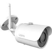
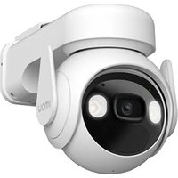
Brand : IMOU
Model : Cube
Category : Camera