
XG-NV33XE - Video projector SHARP - Free user manual and instructions
Find the device manual for free XG-NV33XE SHARP in PDF.


| Product Type | LCD Video Projector |
| Model | XG-NV33XE |
| Brand | Sharp |
| Display Technology | 3 LCD panels (RGB optical shutter), TFT Active Matrix, 786,432 pixels (1024×768) |
| Lens | 1-1.6x zoom, F2.5–3.6, f=47–76 mm |
| Projection Lamp | 120 W UHP lamp (recommended replacement after 2000 hours) |
| Brightness / Contrast | High brightness (not specified numerical value) / 200:1 contrast ratio |
| Supported Resolutions | SXGA (compressed), XGA, SVGA, VGA, Mac up to 1024×768 |
| Audio | Built-in stereo speakers, 2 W + 2 W |
| Inputs | 2× RGB (15-pin D-Sub), 2× audio (3.5 mm stereo minijack), RS-232C, wireless mouse/IR |
| Remote Control | Wireless with laser pointer (Class II, 670 nm, 1 mW max) and mouse functions |
| Image Adjustments | Keystone correction (invert/reverse), zoom, focus, picture/brightness/color adjustments |
| Screen Size | 102 cm (40") to 762 cm (300") diagonal |
| Projection Distance | 1.4 m to 17.5 m |
| Power Supply | AC 110-120/200-240 V, 50/60 Hz |
| Power Consumption | 226 W (operation), 12 W (standby) |
| Dimensions (W×D×H) | 261 × 329 × 137 mm (main body); 266 × 399 × 155 mm (including protrusions) |
| Weight | 6.6 kg |
| Operating Temperature | +5°C to +40°C |
| Storage Temperature | -20°C to +60°C |
| Safety Features | Overheat protection (TEMP. indicator), lamp replacement indicator, Kensington lock slot |
| Maintenance | Clean air filter every 100 hours; replace lamp after ~2000 hours |
| Supplied Accessories | Remote control (batteries included), RGB signal cable, Mac adapter, mouse cables, audio cable, AC cord, lens cap, extra air filter |
| Warranty Notes | User manual includes comprehensive care and safety instructions; servicing by Sharp authorized dealers |
Frequently Asked Questions - XG-NV33XE SHARP
User questions about XG-NV33XE SHARP
0 question about this device. Answer the ones you know or ask your own.
Ask a new question about this device
Download the instructions for your Video projector in PDF format for free! Find your manual XG-NV33XE - SHARP and take your electronic device back in hand. On this page are published all the documents necessary for the use of your device. XG-NV33XE by SHARP.
USER MANUAL XG-NV33XE SHARP
natural_image
Line drawing of a rectangular electronic device with a circular lens and mounting feet (no text or symbols)CEG TECHNICAL
THIS COPY MUST NOT BE REMOVED FROM CEG OFFICE.
This equipment complies with the requirements of Directives 89/336/EEC and 73/23/EEC as amended by 93/68/EEC.
The mains lead of this product is fitted with a non-rewireable (moulded) plug incorporating a 13A fuse. Should the fuse need to be replaced, a BSI or ASTA approved BS 1362 fuse marked 🌐 or ◇ and of the same rating as above, which is also indicated on the pin face of the plug, must be used.
Always refit the fuse cover after replacing the fuse. Never use the plug without the fuse cover fitted.
In the unlikely event of the socket outlet in your home not being compatible with the plug supplied, cut off the mains plug and fit an appropriate type.
DANGER:
The fuse from the cut-off plug should be removed and the cut-off plug destroyed immediately and disposed of in a safe manner.
Under no circumstances should the cut-off plug be inserted elsewhere into a 13A socket outlet, as a serious electric shock may occur.
To fit an appropriate plug to the mains lead, follow the instructions below:
IMPORTANT:
The wires in the mains lead are coloured in accordance with the following code:
Blue: Neutral
Brown: Live
As the colours of the wires in the mains lead of this product may not correspond with the coloured markings identifying the terminals in your plug, proceed as follows:
- The wire which is coloured blue must be connected to the plug terminal which is marked N or coloured black.
• The wire which is coloured brown must be connected to the plug terminal which is marked L or coloured red.
Ensure that neither the brown nor the blue wire is connected to the earth terminal in your three-pin plug. Before replacing the plug cover make sure that:
- If the new fitted plug contains a fuse, its value is the same as that removed from the cut-off plug.
- The cord grip is clamped over the sheath of the mains lead, and not simply over the lead wires.
IF YOU HAVE ANY DOUBT, CONSULT A QUALIFIED ELECTRICIAN.
Welcome to the SHARP Family. We are pleased that you are now the owner of a SHARP Colour LCD Projector built for outstanding quality, reliability and performance.
Every SHARP Colour LCD Projector is adjusted for a proper picture and has passed through the most stringent quality control tests at the factory. We have prepared this OPERATION MANUAL so that you have the ability to adjust the picture and colour to your personal viewing preference. We sincerely hope that you will be satisfied with the quality and performance of your Colour LCD Projector for many years to come.
Please read the instructions carefully, and keep them handy for future reference.
IMPORTANT
For your assistance in reporting the loss or theft of your Colour LCD Projector, please record the Serial Number located on the rear of the projector and retain this information.
Model No.: XG-NV33XE
Serial No.:
Before disposing of the packaging, please be sure that you have checked the contents of the carton thoroughly against the "Supplied Accessories" listed in the operation manual on page 33.
Important Information
WARNING:
Intense light source. Do not look into the beam or view it directly. Be especially careful that children do not look directly into the beam.
WARNING:
To reduce the risk of fire or electric shock, do not expose this appliance to liquids.
CAUTION:
To reduce the risk of electric shock, do not remove cabinet. No user-serviceable parts are inside. Refer servicing to qualified service personnel.
Contents
- Important Information .... 1
- Important Safeguards 3
• Cautions Concerning the Laser Pointer 3 - Notes on Operation 4
• Outstanding Features 4 - Location of Controls 5
- Operating the Wireless Mouse Remote Control 6
- Wireless Mouse Functions 8
- Setting Up the Projector 9
• Using the Image Invert/Reverse Function 11 - Connecting the Projector (RGB 1, 2: Computer) 14
- Input Signals (Recommended Timing) 17
- RGB Adjustment Controls 18
- Basic Operation of the Projector 20
- Adjusting the Picture 23
- Adjusting the Audio 24
- Functions on the Projector 25
• Air Filter Maintenance 27 - Lamp/Maintenance Indicators 28
- Before Calling for Service 28
- Connection Pin Assignments 29
• RS-232C Terminal Specifications 30 - Wired Remote Control Terminal Specifications 32
- Specifications 33
- Dimensions 34
ATTENTION: Please read all of these instructions before you operate your LCD Projector for the first time. Save these instructions for future reference.
For your own protection and prolonged operation of your LCD Projector, be sure to read the following "Important Safeguards" carefully, before use.
This projector has been engineered and manufactured to ensure your personal safety. But IMPROPER USE CAN RESULT IN POTENTIAL ELECTRICAL SHOCK OR FIRE HAZARDS. In order not to defeat the safeguards incorporated into this LCD Projector, observe the following basic rules for its installation, use and servicing.
- Unplug the LCD Projector from the wall outlet before cleaning.
- Do not use liquid cleaners or aerosol cleaners. Use a damp cloth for cleaning.
- Do not use attachments not recommended by the LCD Projector manufacturer, as they may cause hazards.
- Do not use the LCD Projector near water; for example, near a bathtub, washbowl, kitchen sink, laundry tub, in a wet basement, near a swimming pool, etc. Never spill liquid into the projector.
- Do not place the LCD Projector on an unstable cart, stand, or table. The LCD Projector may fall, which may cause serious injury to a child or an adult, and/or serious damage to the unit.
-
Wall or Ceiling Mounting—The product should be mounted to a wall or ceiling only as recommended by the manufacturer.
-
LCD Projector equipment and cart combinations should be moved with care. Quick stops, excessive force, and uneven surfaces may cause the equipment and cart combination to overturn.

-
Slots and openings in the cabinet back and bottom are provided for ventilation. To ensure reliable operation of the LCD Projector and to protect it from overheating, these openings must not be blocked or covered. The openings should never be covered with cloth or other material.
-
This LCD Projector should never be placed near or over a radiator or heating vent. The LCD Projector should not be placed in a built-in installation such as a bookcase unless proper ventilation is provided.
-
The LCD Projector should be operated only from the type of power source indicated on the back of the projector or in the specifications. If you are not sure of the type of power supplied to your home, consult your LCD Projector dealer or local power company.
-
Do not place the LCD Projector where the cord will be abused by persons walking on it.
-
Follow all warnings and instructions marked on the LCD Projector.
-
To prevent damage to the projector due to lightning and power-line surges, unplug the projector from the power outlet, when not in use.
- Do not overload wall outlets and extension cords with too many products, because this can result in fire or electric shock.
- Never push objects of any kind into the LCD Projector through the cabinet slots as they may touch high-voltage points or cause a short circuit. This could result in a fire or electric shock.
- Do not attempt to service the LCD Projector yourself. Opening or removing covers may expose you to dangerous voltage or other hazards. Refer all servicing to qualified service personnel.
- Unplug the LCD Projector equipment from the wall outlet and refer servicing to qualified service personnel under the following conditions:
a. When the power cord or plug is damaged or frayed.
b. If liquid has been spilled into the LCD Projector.
c. If the LCD Projector has been exposed to rain or water.
d. If the LCD Projector does not operate normally when you follow the operating instructions. Adjust only those controls that are covered by the operating instructions, as improper adjustment of other controls may cause damage and will often require extensive work by a qualified technician to restore the LCD Projector to normal operation.
e. If the LCD Projector has been dropped or the cabinet has been damaged.
f. When the LCD Projector exhibits a distinct change in performance—this indicates a need for service.
- When replacement parts are required, be sure the service technician has used replacement parts specified by the manufacturer that have the same characteristics as the original parts. Unauthorised substitutions may result in fire, electric shock, or other hazards.
Cautions Concerning the Laser Pointer
LASER LIGHT WINDOW
natural_image
Line drawing of a handheld electronic device with ports and casing (no text or symbols)Caution:
This product contains a low power laser device. To ensure continued safety, do not remove any cover or attempt to gain access to the inside of the product. Refer all servicing to qualified personnel.
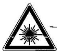
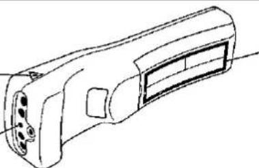
The remote control has a Laser pointer, which emits a Class II Laser beam from the Laser light window shown in the diagram. Do not stare directly into the beam, nor direct the beam at other people. The two marks above are cautions concerning the laser beam. Always use the laser pointer at temperatures between +5°C and +40°C.
| LASER RADIATIONDO NOT STARE INTO BEAMCLASS 2 LASER PRODUCT | RADIACION LASERNO MIRE AL RAYOPRODUCTO LASER CLASE 2 |
| RAYONNEMENT LASERNE PAS REGARDER DANS LE FAISCEAUAPPAREIL À LASER DE CLASSE 2 | |
| LASERSTRAHLUNGNICHT IN DEN STRAHL DERLASERVORRICHTUNG DERKLASSE II BLICKEN | LASERSTHÄLARTITTA INTE IN ILASERSTRÄLENKLASS 2 LASER PRODUKT. |
| LASERSÄTEILYÄÄLÄKATSO SOURAANSÄTEESEENUOKAN 2 LASERTUOTE | LASEROVÉ ZIARENIENEPOZERAJTE SA DO LÜÇALASEROVÝ VÝROBOK TRIEDY 2 |
LASEROVÉ ZÁŘENÍ
NEHLED'TE DO PAPRSKU
LASEROVÝ VÝROBEK TRÍDY 2
Notes on Operation
About the Temperature Monitor Function:
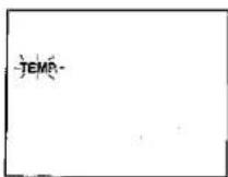
- If the projector starts to overheat due to set-up problems or a dirty air filter, "TEMP." will flash in the upper-left corner of the picture. If the temperature continues to rise, then the lamp will turn off, the TEMPERATURE WARNING indicator will flash, and after a 90-second cooling-off period the power will shut off. Refer to page 28, "Maintenance Indicators," when the "TEMP." warning appears in the picture.
- The cooling fan regulates the internal temperature, and its performance is automatically controlled. The sound of the fan may change during operation due to changes in the fan speed.
Outstanding Features

natural_image
Line drawing of a rectangular electronic device with a circular lens and mounting feet (no text or symbols)Allows easy projection of large screen, full-colour computer and video images.
- Can be projected directly onto a video screen or white wall.
- Lightweight, convergence-free system for easy installation.
DIRECT COMPUTER COMPATIBILITY
A multi-scan RGB Input accepts signals from SXGA (1,280 dots × 1,024 lines compressed), XGA (1,024 dots × 768 lines), SVGA (800 dots × 600 lines), VGA (640 dots × 480 lines) and Mac (1,024 dots × 768 lines maximum) compatible computers without the need for any additional hardware.
HIGH PICTURE QUALITY
The three LCD panels contain 786,432 × RGB pixels to achieve exceptionally bright, high quality images.
INTELLIGENT COMPRESSION
SXGA images are compressed and projected without image data loss.
VERSATILE REMOTE CONTROL
• Built-in wireless mouse allows simultaneous operation of projector and computer.
• Built-in Laser Pointer for professional presentations.
FLEXIBLE USE
- In addition to the standard front projection mode, the menu driven functions can be used to instantly reverse the image for rear projection, and invert the image for ceiling mounting.
- Screen projection size adjusts from 102 cm (40 inches) to 762 cm (300 inches).
BUILT-IN STEREO SPEAKERS
Built in 2 W + 2 W stereo amplifiers and speakers eliminate the need for external audio components.
USE WITH "PLUG AND PLAY"
"Plug and Play" compatible with VESA DDC 1 and DDC 2B standards.

Cautions:
- The exhaust vent, the lamp cage cover and adjacent areas may be extremely hot during projector operation. To prevent injury, do not touch these areas until they have sufficiently cooled.
- Allow at least 10 cm of space between the cooling fan (exhaust vent) and the other nearest wall or obstruction.
- If the cooling fan becomes obstructed, a protection device will automatically turn off the projector lamp. This does not indicate a malfunction. Remove the projector plug from the wall outlet and wait 10 minutes. Then turn on the power by plugging the cord back in. This will return the projector to its normal mode.
SIDE AND REAR VIEW
Security Lock Anchor This projector has a Kensington Security Standard connector for use with a Kensington MicroSaver Security System. Refer to the information that came with the system for instructions on how to use it to secure this model.
Note:
- Be sure to use the computer control cable when connecting the PC CONTROL terminals.

- PC CONTROL 1: Use the supplied computer control cable when operating the remote control as a wireless mouse or when controlling the projector from the RS-232C terminal.
- PC CONTROL 2: Use the computer control cable (CTANZ0711CE01) (sold separately) when operating the remote control as a wireless mouse.
Notes:
- RS-232C does not function when connected to PC CONTROL 2.
• See page 14 for connection.
Operating the Wireless Mouse Remote Control
The functions of your personal computer's mouse have been built into the remote control enabling you to operate your projector and personal computer with the remote control.
- Slide the MAIN POWER switch on the rear of the projector on.
- Press the POWER ON button on the front panel of the remote control to turn the projector power on.
- When using the remote control as a wireless mouse, move the MOUSE/ADJUSTMENT switch to the MOUSE position. When using the remote control to operate the projector, move the MOUSE/ADJUSTMENT switch to the ADJ. position. To activate the remote control key back-light feature, press the LIGHT button on the remote control. The colours of the buttons will change as shown in the table at the bottom of this page.
Wireless Mouse Remote Control

Using the remote control in a dark room
- Press the LIGHT button to turn on the back-lights for the operation buttons for about 5 seconds. The back-light colours are described in the table to the right.
Note:
- If the MAIN POWER switch on the remote control is left on for more than 10 minutes without operation, the power will automatically turn off. To turn the power back on, press any button on the remote control for at least one second.
| Button name | Position of MOUSE/ADJUSTMENT switch | |
| MOUSE | ADJ. | |
| LASER POINTER/MENU | LASER POINTER (GREEN) | MENU (RED) |
| RIGHT-CLICK/ENTER | RIGHT-CLICK (GREEN) | ENTER (RED) |
| MOUSE/ADJUSTMENT | MOUSE (NOT LIT) | ADJ. ◀/▶, ▼/▲ (NOT LIT) |
| LEFT-CLICK | ON (NOT LIT) | — |
| BLACK SCREEN | BLACK SCREEN (RED) | |
| POWER ON/OFF | ON (RED) | |
| VOLUME UP-DOWN | ||
| MUTE | ||
| DATA 1 | ||
| DATA 2 | ||
| INPUT CHECK | ||
TOP VIEW
REMOTE CONTROL SIGNAL TRANSMITTER
natural_image
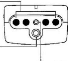
Pure electrical outlet diagram without any text, numbers, or symbolsWIRED REMOTE CONTROL INPUT (3.5 mm Minijack)
LASER LIGHT WINDOW
Laser light shines out of this window.
Using the optional cable with the remote control
When the remote control cannot be used due to the range or positioning of the projector (rear projection, etc.), connect the optional cable from the Wired Remote Control Input jack on the remote control to the Wired Remote Input on the rear of the projector.
Note:
- The signal transmitter does not function when the optional cable is connected to the remote control.
| LASER RADIATIONDO NOT STARE INTO BEAMCLASS 2 LASER PRODUCT | RADIACION LASERNO MIRE AL RAYOPRODUCTO LASER CLASE 2 |
| RAYONNEMENT LASERNE PAS REGARDER DANS LE FAISCEAUAPPAREIL À LASER DE CLASSE 2 | |
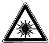
The laser pointer on the remote control emits a laser beam from the laser light window shown in the figure to the left. The laser emitted is a class II laser; therefore, do not look into the laser window or shine the laser beam on yourself or other people. The two marks to the left are the caution labels for the laser beam.
Always use the laser pointer at temperatures between +5°C and +40°C.
REAR VIEW

Inserting the batteries
Remove the battery cover as shown and insert four AA size batteries making sure their polarities match the (+) and (−) marks inside the battery compartment.
Notes:
Incorrect use of batteries may cause them to leak or burst.
- Insert the batteries with the (+) and (−) polarities as indicated.
- Remove the batteries if the remote control will not be operated for an extended period of time.
- Maintain the batteries in a clean condition.
- Do not mix different brands of batteries. The life expectancy of the new batteries will be shortened and the old batteries may leak.
- When the batteries have been used up, remove them immediately to prevent leakage and damage. Leaked battery fluid may irritate the skin. Remove any battery fluid by wiping with a cloth.
- Due to storage conditions and the shelf life of the supplied batteries, they may run out after a short time. If so, replace them with new batteries as soon as possible.
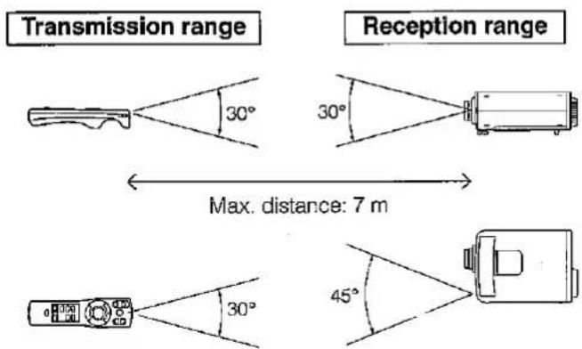
Remote control positioning
Use the remote control as shown in the figures on the left.
Note:
- The signal from the remote control can be reflected off the screen for easy operation. However, the effective distance of the signal may differ due to the screen material.
Connection Example
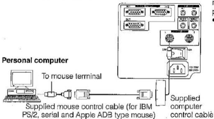
The wireless mouse functions and laser pointer on the remote control can help you create a more professional presentation.
- By connecting the supplied computer control cable to the PC CONTROL terminal on your projector and the supplied mouse control cables to the mouse terminal on your personal computer, you can use the wireless mouse on the remote control, instead of the mouse equipped with your personal computer, to operate your personal computer. The wireless mouse functions will work with personal computers compatible with IBM PS/2, serial (RS-232C) or Apple ADB type mouse systems.
Functions and Operations


- First, connect the units as shown above, and turn the projector power on.
• Second, turn the computer power on. - Next, slide the MAIN POWER switch on the side of the remote control.
- When using the remote control as a wireless mouse, move the MOUSE/ADJUSTMENT switch to the MOUSE position.
Notes:
- In some situations the wireless mouse may be inoperable if your computer port is not correctly set-up. Please refer to your computer owners manual for details on setting-up/installing the correct mouse driver.
- Be sure to use the computer control cable when connecting the PC CONTROL terminals.
- Do not connect or remove the mouse control cables and computer control cable to/from your computer while it is on. This may damage your computer.
- Only one set of connection cables is supplied with your projector. For additional connection cables, contact your nearest Sharp Authorised LCD Projector Dealer or Service Centre.
- Do not connect the mouse input terminal for IBM/Mac and the mouse input terminal for PC98 simultaneously.
MOUSE buttons
By lightly pressing the up/down and right/left arrow buttons located on the front of the remote control, you can move the mouse cursor on your monitor screen.

natural_image
Simple diagram with four arrows pointing outward from a central arrow, no text or symbols presentMouse cursor
Note:
- The amount of pressure applied to the MOUSE button determines the speed the mouse cursor travels. Pressing lightly on the periphery of the MOUSE button makes the mouse cursor move slowly. Pressing hard makes it move quickly.
LEFT-CLICK button
The LEFT-CLICK button on the back of the remote control corresponds to the left button of the mouse on two-button mouse systems.
RIGHT-CLICK button
The RIGHT-CLICK button on the front of the remote control corresponds to the right button on two-button mouse systems.
Note: For one-button mouse systems use either the LEFT-CLICK or RIGHT-CLICK button.
LASER POINTER button
Press the LASER POINTER button to activate the laser pointer.
When the button is pressed, the light stays on; when the button is released, the light goes off. However, even when the button is pressed continuously, the light automatically goes off 1 minute after it goes on. To turn it on again press the laser pointer button one more time.
| LASER RADIATIONDO NOT STARE INTO BEAMCLASS 2 LASER PRODUCT | RADIACION LASERNO MIRE AL RAYOPRODUCTO LASER CLASE 2 |
| RAYONNEMENT LASERNE PAS REGARDER DANS LE FAISCEAUAPPAREIL À LASER DE CLASSE 2 | |

The laser pointer on the remote control emits a laser beam from the laser light window. The laser emitted is a class II laser; therefore, do not look into the laser window or shine the laser beam on yourself or other people. The two marks to the left are the caution labels for the laser beam.
Always use the laser pointer at temperatures between +5°C and +40°C.
Using the Focus and Zoom
- Zoom, Focus and Reversed/Inverted Image mode functions broaden your options for projector placement.
• See pages 10, 11 and 12 for details on projector setup.

2

1. Turn on the MAIN POWER.
Turn on the MAIN POWER switch on the back of the projector.
2. Turn on the POWER.
Press the POWER ON/OFF button on the projector or the POWER ON button on the remote control to turn on the power.
3

3. Rotating the zoom ring (from the housed position to the wide angle position)
Rotate the zoom ring on the lens until it clicks. The picture can be adjusted within the zoom range.
4

4. Adjusting the focus
Rotate the lens focusing ring until the image on the screen is in focus.
5

5. Adjusting the zoom
Rotate the zoom ring. The picture can be adjusted to the desired size within the zoom range.
Projector Distance and Picture Size Relationship
- The zoom lens allows adjustment of the image size within the projector's range.
- For optimum picture adjustment, the projector should be placed and adjusted at a distance between 1.4 m and 17.5 m from the screen.
Distance from screen
Picture size: 254 cm (100 inches)
| Picture size (diag.) | Projection distance (L) | |
| Maximum projection distance | Minimum projection distance | |
| 762 cm (300 inches) | 17.5 m | 10.9 m |
| 508 cm (200 inches) | 11.7 m | 7.3 m |
| 381 cm (150 inches) | 8.7 m | 5.4 m |
| 254 cm (100 inches) | 5.8 m | 3.6 m |
| 203 cm (80 inches) | 4.6 m | 2.9 m |
| 152 cm (60 inches) | 3.5 m | 2.1 m |
| 102 cm (40 inches) | 2.3 m | 1.4 m |
Zoom adjustment range: 5.8 m–3.6 m

- Above is an illustration of maximum and minimum projection distances for the XG-NV33XE with a picture size of 254 cm (100 inches). Move the projector forward or backward if the edges of the image are distorted.
Height of Projector
Adjust to match the setup configuration.

| Picture size (diag.) | Distance from lens centre to lower edge of screen (H) |
| 762 cm (300 inches) | 66 cm |
| 508 cm (200 inches) | 44 cm |
| 381 cm (150 inches) | 33 cm |
| 254 cm (100 inches) | 22 cm |
| 203 cm (80 inches) | 18 cm |
| 152 cm (60 inches) | 13 cm |
| 102 cm (40 inches) | 9 cm |
- Ceiling Mount
When the projector is in the inverted position, use the high edge of the screen as the base line.

Note:
- Optimal Image quality is produced with the projector positioned perpendicular to the screen with all feet flat and level.
Using the Image Invert/Reverse Function
This projector is equipped with an image invert/reverse function. The projected image can be inverted or reversed by using the MENU button and the ADJUSTMENT ▼/▲ and ◀/▶ buttons.
On-Screen Display
1

2
![1QA 3DAM1 [1970] 9210 HXOZ KJ8 [1970] YAJ21C TUKI [1970] .3KSYH [1970] T33YU .132.1A OK3 500 .0A](/content/2026/05/992483/images/a2dad61e7bef6b8fcb7e90a1ba02a837b9225b20dfcbbb6445e53307ab6e20a7.jpg)
3

4
![V01' END V02' 281' [IMAGE] [OK] [IMAGE] [OK] [IMAGE] [OK] [IMAGE] [OK]](/content/2026/05/992483/images/01d54fb7bdcfa9a8cc910945bce2bdd8a2b51c8481cbfa2e210ea5b43744f877.jpg)
1. Press the MENU button.
With the MENU screen displayed, press the AD-JUSTMENT ▼/▲ buttons to select "IMAGE ADJ." Then press the ENTER button to display the IMAGE ADJ. screen.
- The last MENU screen selected is indicated for about 30 seconds.
2. Reversed Image Mode
In the IMAGE ADJ. menu, press the ADJUSTMENT ▼/▲ buttons to select "REVERSE". Then press the ADJUSTMENT ◀/▶ buttons to select "ON". The reversed image will appear.
3. Inverted Image Mode
In the IMAGE ADJ. menu, press the ADJUSTMENT ▼/▲ buttons to select "INVERT". Then press the ADJUSTMENT ◀/▶ buttons to select "ON". The inverted image will appear.
4. Reversed Inverted Image Mode
In the IMAGE ADJ. menu, set the REVERSE and INVERT functions to "ON". The reversed inverted image will appear.
5. Press the MENU button anytime to exit IMAGE ADJ.
How to set up the projector and screen
Cautions: When setting up the projector
- For minimal servicing and to maintain high image quality, SHARP recommends that this projector be installed in an area free from humidity, dust and cigarette smoke. If the projector is used in these environments, the lens and filter will need to be cleaned (or the filter replaced) more often, and internal cleaning may become necessary. As long as the projector is regularly cleaned, use in these environments will not reduce the overall operation life of the unit. Internal cleaning should only be performed by a Sharp Authorised LCD Projector Dealer.
- Do not expose to extreme heat or cold. Operating temperature: +5°C to +40°C Storage temperature: -20°C to +60°C
-
Do not tilt the projector more than 5^ .
-
Position the screen so that it is not in direct sunlight or room light. Light falling directly onto the screen washes out colours, making viewing difficult. Close the curtains and dim the lights when using the screen in a bright or sunny room.
- The best picture will be obtained when the projector is at a 90 degree angle to the screen. Position the projector and screen as shown.
Example of a standard setup
TOP VIEW

The projector lens should be centred in the middle of the screen.
SIDE VIEW

If the projector and screen are not centred properly, the picture will be distorted, making viewing difficult.
Using the horizontal reverse function makes the following setups possible.
Example of a reversed image setup
- By placing a mirror (normal flat type) in front of the lens and using the horizontal reverse function, the image reflected from the mirror can be projected onto the screen.
- Rear projection with a rear projection screen is also possible when using the horizontal reverse function.
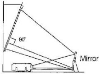
The projector lens should be centred in the middle of the screen.

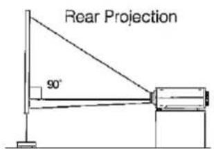
If the projector and screen are not centred properly, the picture will be distorted, making viewing difficult.
Example of a ceiling-mount setup
Before mounting the projector, be sure to contact your nearest Sharp Authorised LCD Projector Dealer to obtain the manufacturer recommended ceiling mount bracket (sold separately). (AN-NV2T Ceiling Mount Bracket, AN-TK201/AN-TK202 Extension Tube for AN-NV2T.)
TOP VIEW

SIDE VIEW

- If the relative positions of the projector and the screen are not properly adjusted, the picture will be distorted.
Note:
- A polarising screen cannot be used with this projector.
Adjusting the Height of the Picture
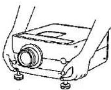
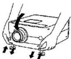
Use the adjuster release to adjust the angle of the projector and height of the picture. Minor adjustments can be made with the adjusters.

1
natural_image
Line drawing of hands operating a camera module with buttons (no text or symbols)2

natural_image
Line drawing of a mechanical device with two buttons and a central knob (no text or symbols)3


natural_image
Illustration of hands operating a mechanical device with buttons and arrows indicating motion (no text or symbols)- Press the adjuster release and lift the projector to the desired angle with both hands.
- The adjuster legs will extend to the surface of the table.
- Remove your hand from the adjuster release.
- The adjuster legs will lock in position. Release the projector once you are sure the adjuster legs have locked in position.
- Make any minor adjustments necessary.
- Turn the adjusters to further adjust the angle of the projector.
Returning the projector to its original position
- While holding the projector with both hands, press the adjuster release and slowly lower the projector to its original position.
Notes:
- Adjustable up to approximately 5^ from the horizontal.
- When adjustments are made with the adjusters, the picture may become distorted, depending on the relative positions of the projector and the screen.
- After adjusting, in some cases, all of the adjuster legs may not be resting on the table. To prevent the projector from wobbling, adjust the adjuster legs so that they firmly contact the table.
Cautions:
- Do not press the adjuster release when the adjuster legs are extended without firmly holding the projector.
- When lowering the projector, be careful not to get your fingers caught in the area between the adjusters and the projector.
- Do not hold the lens when lifting or lowering the projector.
Transporting the Projector
Use the carrying handle when carrying the projector.
When transporting the projector, carry it by the handle located on the side of the unit.
Note:
- Always put on the lens cap to prevent damage to the lens when transporting the projector.
Caution:
- Do not lift or carry the projector by the lens or the lens cap as this may damage the lens.

Connecting the Projector (RGB 1, 2: Computer)

flowchart
graph TD
    A["Personal computer"] -->|To display input terminal| B["15-pin D-Sub"]
    A -->|To display input terminal| C["Macintosh Adaptor (Supplied)"]
    A -->|To display input terminal| D["9-pin D-Sub"]
    A -->|To display input terminal| E["RS-232C cable (Cross Type, sold separately)"]
    A -->|To display input terminal| F["Computer Control Cable (with mouse/RS-232C input terminal) (Supplied)"]
    G["Rear terminals"] --> H["15-pin D-Sub"]
    G --> I["RGB Signal Cable (Supplied)"]
    G --> J["Audio Cable for Personal Computer (Supplied)"]
    K["Note: Please carefully read the manual of the computer you will be connecting. Before connecting, be sure to turn both the projector and the computer off. After making all connections, turn the projector on first. The computer should always be turned on last."] --> L["15-pin D-Sub"]
    M["Note: The arrows (←, ↔) indicate the direction of the signals."] --> N["15-pin D-Sub"]
    O["Note: By using RGB INPUT 2 and PC CONTROL 2, another computer can be connected to and operated with the projector. The RS-232C func."] --> P["6-pin DIN Mouse Control Cable for IBM PS/2 (Supplied)"]
    O --> Q["4-pin DIN Mouse Control Cable for Macintosh Series (Supplied)"]
    R["Note: Computer Control Cable (with mouse/RS-232C input terminal) (Supplied)"] --> S["9-pin D-Sub"]
    T["Note: Computer Control Cable (with mouse/RS-232C input terminal) (Supplied)"] --> U["9-pin D-Sub"]
- You can connect your projector to a computer for easy projection of full colour computer images and an external monitor for simultaneous viewing. See pages 15 and 16 for details of the connections.
- Refer to page 17 for a list of personal computers connectable to the projector. Use with computers other than those listed may cause some of the functions not to work.
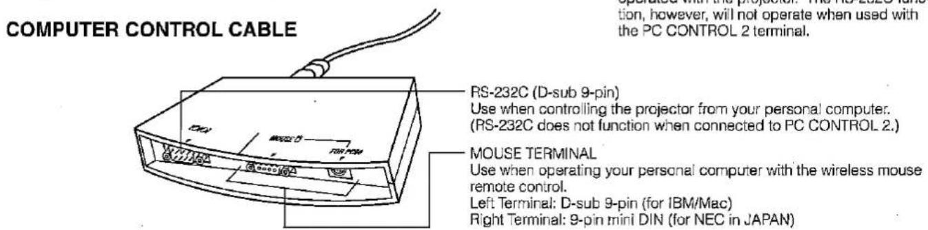
- When the RS-232C terminal on this unit is connected to a personal computer via an RS-232C cable (cross type) and the supplied computer control cable, the personal computer can control the projector and the status of the projector can be checked. See pages 30 and 31 for details.
- By connecting the supplied computer control cable to the PC CONTROL terminal on your projector and the supplied mouse control cables to the mouse terminal on your personal computer, you can use the wireless mouse on the remote control, instead of the mouse equipped with your personal computer, to operate your personal computer. Refer to page 8 for details.
Notes:
- The RS-232C function will only operate when the connection cable is connected to the PC CONTROL 1 terminal on the projector.
- The wireless mouse or RS-232C function may not operate if your computer port is not correctly set-up. Please refer to your computer owners manual for details on setting-up/installing the correct mouse driver.
- Do not connect or remove the computer control cable, mouse control cables, or RS-232C cable to/from your computer while it is on. This may damage your computer.
- Do not connect to the mouse input terminals on the computer control cable for IBM/Mac and PC98 simultaneously.
- Be sure to use the supplied computer control cable when connecting the PC CONTROL terminals.
"Plug and Play" Function
This projector is compatible with VESA DDC 1 and DDC 2B standards. This projector and a VESA DDC compatible computer will communicate their setting requirements, allowing for quick and easy set-up.
Note:
- The DDC, "Plug and Play" function of this projector is only functional when used in conjunction with a VESA DDC compatible computer.
Connecting to the Computer RGB Input (RGB 1, 2)/Output Terminals
You can connect your projector to a computer for easy projection of full-colour computer images, and an external monitor for simultaneous viewing.
1

flowchart
graph TD
    A["RGB Signal Input Socket"] --> B["RGB Signal Cable (Supplied)"]
    B --> C["IGM-PC (VGA, SVGA, XGA, SXGA) Series (computer)"]
    B --> D["IGM-PC (VGA, SVGA, XGA, SXGA) Series (computer)"]
    E["Rear view of the projector"] --> F["RGB Signal Output Socket"]
    F --> G["IGM-PC (VGA, SVGA, XGA, SXGA) Series (computer)"]
1. Connecting to an IBM-PC (VGA, SVGA, XGA, SXGA) Series computer—1,280 × 1,024 maximum resolution
Plug one end of the RGB signal cable into the RGB INPUT terminal on the projector and the other end into the RGB signal output terminal on the computer, and secure the plugs by tightening the thumb screws.
Notes:
- This connection is possible only when using a computer with a VGA/SVGA/XGA/SXGA or Mac display output port.
- By using RGB INPUT 2 and PC CONTROL 2, another computer can be connected to and operated with the projector.
2 1
Macintosh Adaptor (Supplied)
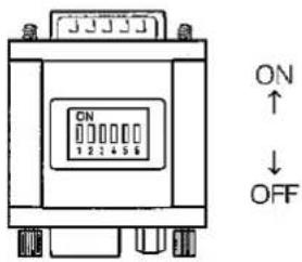
2. Connecting to a Macintosh Series Computer
640 × 480, 832 × 624 or 1,024 × 768 resolution
2
Macintosh Adaptor (Supplied)
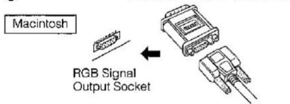
① Set the proper switches on the supplied adaptor.
- For 640 × 480 resolution, set switches 1 and 2 to "ON" and 3, 4, 5 and 6 to "OFF".
- For 832 × 624 resolution, set switches 2 and 4 to "ON" and 1, 3, 5 and 6 to "OFF".
- For 1,024 × 768 resolution, set switches 2 and 3 to "ON" and 1, 4, 5 and 6 to "OFF".
② Connect the supplied Macintosh adaptor to the RGB signal output terminal on your Macintosh Series computer, as shown on the left, and secure the plugs by tightening the thumb screws.
3
Rear view of the projector
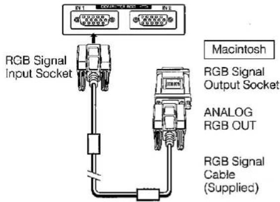
③ Firmly plug one end of the supplied RGB signal cable into the RGB input terminal on the projector and the other end to the Macintosh adaptor on the computer, and secure the plugs by tightening the thumb screws.
Notes:
- Be sure to use the supplied Macintosh adaptor.
- Be sure the switches on the adaptor are properly set.
- Once the adaptor is connected to a computer and the computer is turned on, the display mode cannot be changed even if the switches on the adaptor are reset.
- The supplied adaptor is only for use with H-SYNC and V-SYNC output. When connecting a Macintosh Series computer that only outputs C-SYNC, use a special C-SYNC output adaptor (sold separately).
4
5

flowchart
graph TD
    A["External IBM-PC monitor"] -->|Direct connection| B["Switch"]
    B --> C["Optional Macintosh adaptor cable"]
    C --> D["External Macintosh monitor"]
    style A fill:#f9f,stroke:#333
    style D fill:#bbf,stroke:#333
3. Connecting to other compatible computers
When connecting the projector to a compatible computer other than an IBM-PC (VGA/SVGA/XGA/SXGA) or Macintosh series, a separate cable may be needed. Please contact your dealer for ordering information.
Notes:
- Connecting computers other than the recommended types may result in damage to the projector, the computer, or both.
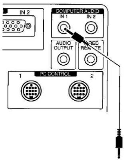
- Connect the audio from the computer to the COMPUTER AUDIO INPUT terminal.
4. Connecting to the COMPUTER AUDIO INPUT
- The COMPUTER AUDIO INPUT 1 accepts audio from the COMPUTER RGB 1 input, and the COMPUTER AUDIO INPUT 2 accepts audio from the COMPUTER RGB 2 input.
- Connect a 3.5 mm Stereo Minijack cable from the audio output terminal on the computer to the COMPUTER AUDIO INPUT terminal on the projector.
5. Connecting an external monitor
Connect your computer monitor to the projector's COMPUTER RGB OUTPUT terminal to view images simultaneously on the external monitor and the projection screen. Select either RGB 1 or RGB 2 to output the images to the monitor.
Caution (Apple Macintosh):
Do not connect the COMPUTER RGB OUTPUT to any monitor except the following:
Apple Colour RGB Monitor 13"/14" (640 × 480), 16"/17" (832 × 624) or 19" (1,024 × 768)
The output signal from the projector to the monitor should be the same as the input signal from the computer to the projector.
Examples:
Input 13"/14" (640 × 480) → Output (640 × 480)
Input 16"/17" (832 × 624) → Output (832 × 624)
Input 19" (1,024 × 768) → Output (1,024 × 768)
Note:
- The supplied adaptor is only for use with H-SYNC and V-SYNC output. No picture will appear when connected to monitors that only use C-SYNC.
Notes:
- When using the projector with an external IBM-PC monitor, connect the monitor using the supplied cable. When using the projector with a Macintosh monitor, an optional adaptor cable is required. Before using any other type of monitor, carefully check the monitor's interface specifications and make sure that they match the specifications of the projector's interface.
- The external monitor output will only display an analog computer input signal. It will not display a digital or video input signal. To split the composite video signal, use a video distribution amplifier. This is available from your local dealer. The computer RGB output will only loop through the same signal connected to the computer RGB input. (VGA IN → VGA OUT, Mac IN → Mac OUT)
Input Signals (Recommended Timing)
For IBM and compatibles
Input signals:
The video output signal timing of different types of video signals are shown below for reference.

For Apple Macintosh Series

| NODE | IBM | IBM | IBM | IBM | IBM | IBM | IBM | IBM | IBM | IBM | Apple | Apple | Apple | Apple | ||||||
| VGA | VESA | SVGA | SVGA | SVGA | SVGA | XGA | XGA | XGA | SXCA | SXCA | MacintoshTM Data | MacintoshTM LC | MacintoshTM | |||||||
| Text | Graphic | Graphic | Graphic | VESA Guideline | VESA Standard | VESA Standard | VESA Guideline | VESA Standard | VESA Standard | VESA Standard | 13" Monitor | 13" Monitor | 10" Monitor | 19" Monitor | ||||||
| 720 dots | 540 dots | 640 dots | 800 dots | 800 dots | 800 dots | 800 dots | 1,024 dots | 1,024 dots | 1,024 dots | 1,260 dots | 1,260 dots | 640 dots | 640 dots | 632 dots | ||||||
| 350 lines | 400 lines | 350 lines | 400 lines | 480 lines | 480 lines | 600 lines | 600 lines | 600 lines | 600 lines | 768 lines | 768 lines | 768 lines | 1,024 lines | 1,024 lines | 480 lines | 480 lines | 624 lines | |||
| VIDEO | LEVEL | 0.7Vp-p 75Ω load | 0.7Vp-p 75Ω load | 0.7Vp-p 75Ω load | 0.7Vp-p 75Ω load | 0.7Vp-p 75Ω load | 0.7Vp-p 75Ω load | 0.7Vp-p 75Ω load | 0.7Vp-p 75Ω load | 0.7Vp-p 75Ω load | 0.7Vp-p 75Ω load | 1Vp-p max. 75Ω load | 0.7Vp-p max. 75Ω load | 0.7Vp-p max. 75Ω load | 0.7Vp-p max. 75Ω load | |||||
| TYPE | R·G·B | R·G·B | R·G·B | R·G·B | R·G·B | R·G·B | R·G·B | R·G·B | R·G·B | R·G·B | R·G·B C.SYNC | R·G·B C.SYNC | R·G·B C.SYNC | R·G·B C.SYNC | ||||||
| HSYNC | FRONT PORCH a | dot | 17 | 14 | 24 | 24 | 40 | 58 | 15 | 24 | 24 | 18 | 48 | 18 | 64 | 78 | 31 | |||
| SYNC b | dot | 100 | 93 | 40 | 72 | 128 | 120 | 80 | 136 | 136 | 96 | 112 | 144 | 64 | 62 | 65 | ||||
| BACK PORCH c | dot | 55 | 50 | 126 | 128 | 88 | 64 | 180 | 160 | 144 | 178 | 248 | 249 | 98 | 116 | 224 | ||||
| VIDEO PERIOD d | dot | 720 | 640 | 640 | 800 | 800 | 800 | 800 | 1,024 | 1,024 | 1,024 | 1,260 | 1,260 | 640 | 640 | 832 | ||||
| 1H (a+b+c+d) | dot | 900 | 800 | 832 | 1,024 | 1,058 | 1,040 | 1,056 | 1,944 | 1,920 | 1,312 | 1,588 | 1,686 | 864 | 896 | 1,152 | ||||
| μs | 31.7774 | 31.7776 | 28.419 | 28.444 | 28.400 | 20.800 | 21.903 | 20.677 | 17.707 | 18.660 | 15.6 | 12.5 | 28.5714 | 28.595 | 20.124 | |||||
| 1 doc | ns | 35.3082 | 39.7219 | 31.748 | 27.777 | 25.500 | 20.000 | 20.202 | 15.386 | 13.3 | 12.7 | 9.3 | 7.4 | 33.0858 | 31.914063 | 17.408 | ||||
| 1/H | MHz | 31.4689 | 31.4688 | 37.660 | 38.158 | 37.579 | 48.077 | 48.875 | 48.363 | 58.478 | 60.023 | 63.961 | 79.976 | 35.0300 | 34.971149 | 49.883 | ||||
| 1/dot | MHz | 28.322 | 25.175 | 31.800 | 36.000 | 40.000 | 50.000 | 49.800 | 65.000 | 75.0 | 78.75 | 105.000 | 195.000 | 30.9400 | 31.334149 | 57.246 | ||||
| LEVEL | TTL | TTL | TTL | TTL | TTL | TTL | TTL | TTL | TTL | TTL | TTL | TTL | TTL | TTL | TTL | TTL | ||||
| SYNC POLARITY | +/- | + | - | + | - | - | - | +/- | + | + | - | - | - | + | + | + | - | - | - | |
| VSYNC | FRONT PORCH w | H | 38 | 13 | 38 | 13 | 11 | 9 | 1 | 1 | 37 | 1 | 3 | 3 | 1 | 1 | 1 | 3 | 3 | 1 |
| SYNC x | H | 2 | 2 | 2 | 2 | 2 | 3 | 2 | 4 | 6 | 3 | 6 | 6 | 3 | 3 | 3 | 3 | 3 | 3 | |
| BACK PORCH y | H | 59 | 34 | 59 | 34 | 32 | 26 | 22 | 23 | 23 | 21 | 29 | 29 | 28 | 38 | 30 | 39 | 39 | 30 | |
| VIDEO PERIOD z | H | 360 | 400 | 380 | 400 | 480 | 480 | 500 | 500 | 600 | 600 | 788 | 768 | 768 | 1,024 | 1,024 | 480 | 480 | 624 | |
| 1V (w+x+y+z) | H | 449 | 449 | 449 | 449 | 525 | 520 | 625 | 628 | 666 | 625 | 606 | 605 | 500 | 1,066 | 1,058 | 625 | 525 | 607 | |
| ms | 14.2681 | 14.2681 | 14.2681 | 14.2681 | 16.6932 | 13.735 | 17.778 | 16.679 | 13.653 | 13.333 | 16.668 | 14.272 | 13.323 | 16.7 | 16.7 | 15.00 | 15.00 | 13.423 | ||
| 1/V | Hz | 70.0998 | 70.0998 | 70.0998 | 70.0998 | 95.9405 | 72.808 | 56.250 | 60.317 | 72.188 | 75.000 | 60.008 | 70.089 | 75.025 | 60.020 | 75.025 | 66.67 | 65.67 | 74.502 | |
| LEVEL | TTL | TTL | TTL | TTL | TTL | TTL | TTL | TTL | TTL | TTL | TTL | TTL | TTL | TTL | TTL | TTL | TTL | TTL | ||
| SYNC POLARITY | +/- | - | + | - | + | - | - | +/- | + | + | + | - | - | + | + | + | - | - | - | |
Notes:
- When connecting a notebook computer to the data-projector for display on an (800 × 600) LCD screen, the screen may not show a full picture image. See page 19, "Computer Mode Memory Adjustments" for details.
- This projector may not be able to display images from notebook computers in simultaneous (CRT/LCD) mode. If this occurs, turn off the LCD display on the notebook computer and output the display data in "CRT only" mode. Details on how to change display modes can be found in your notebook computer's operation manual.
When displaying computer patterns which repeat every other dot (tiling, vertical stripes, etc.), interference may occur between the LCD pixels, causing flickering, vertical stripes, or contrast irregularities in portions of the screen. Should this occur, use the ADJUSTMENT ◀/▶ buttons for HORIZONTAL (LEFT/RIGHT) and VERTICAL (UP/DOWN) position adjustments to adjust for the optimum picture.
RGB Input Adjustments (CLOCK, PHASE, V-POS and H-POS)
2
![On-Screen Display CTRL [INPUT ADJ.] CLOCK B PHASE B H-POS D V-POS O MODE [OFF] RESET MEMORY SELECT [SL] NEXT [ADJ.] END](/content/2026/05/992483/images/8fc2cce2bbbf848a72ace1af16b97102f36ad05f47e2976905cb24569b687c03.jpg)
- Select the input of the image you want to adjust (RGB 1 or 2) with the INPUT SELECT button and press the MENU button.
With the MENU screen displayed, press the ADJUSTMENT ▼/▲ buttons to select "RGB 1 INPUT ADJ." Then press the ENTER button to display the RGB 1 INPUT ADJ. screen.
- Select the item you wish to adjust with the ADJUSTMENT ▼/▲ buttons. Adjust the item with the ADJUSTMENT ◀/▶ buttons.
Note:
- To display only the item that you want to adjust, press the ENTER button after selecting the item with the ADJUSTMENT ▼/▲ buttons. Then adjust the item with the ADJUSTMENT ◀/▶ buttons.
3. Press the MENU button anytime to exit RGB INPUT ADJ.
Description of Adjustment Items
CLOCK SPEED ADJUSTMENT (FAST/SLOW)
- Adjust the input signal horizontal frequency and the dot clock so that the screen display is normal.
PHASE ADJUSTMENT (UP/DOWN)
• Used to reduce image distortion or improve contrast.
HORIZONTAL POSITION ADJUSTMENT (LEFT/RIGHT)
• Used to centre the on-screen image by moving it to the left or right.
VERTICAL POSITION ADJUSTMENT (UP/DOWN)
• Used to centre the on-screen image by moving it up or down.
MODE ADJUSTMENT
CONNECTING TO IBM-PC COMPUTERS
- Ordinarily, the type of input signal is detected and the correct resolution mode (Text or Graphics) is automatically selected. However, for the following signals, set MODE to ON or OFF to select the projector's resolution mode to match the computer display mode properly.
720 dots × 400 lines, 720 dots × 350 lines (Text Mode) 640 dots × 400 lines, 640 dots × 350 lines (Graphic Mode)
- For graphic mode, select MODE and set the MODE to ON.
- For text mode, select MODE again at this time, and set MODE to OFF.
CONNECTING TO MACINTOSH LC/II SERIES COMPUTERS
- When connecting to a Macintosh II with 35 kHz Dot Frequency, select MODE and set MODE to ON.
- When connecting to a Macintosh LC Series computer with 34.97 kHz Dot Frequency, set MODE to OFF.
- When connecting to third party video cards and other Macintosh computers, set MODE to ON or OFF to select the correct display mode.
- When the input signal is automatically detected or when there is no input signal, MODE (---) appears on the screen and the display mode cannot be changed.
INITIAL RESET
- To return the H-POS, V-POS, PHASE and CLOCK adjustments to their initial settings, select RESET and then press the ENTER button.
MEMORY SELECT
• Used to store up to seven computer mode adjustments.
Note:
- Avoid displaying computer patterns which repeat every other line (horizontal stripes). (Flickering may occur, making the picture hard to see.)
1 When RGB 1 or 2 is selected.
On-Screen Display

flowchart
graph TD
    A["ROU INPUT AD"] --> B["CLOCK 0"]
    B --> C["PHASE 0"]
    C --> D["H-POS 0"]
    D --> E["V-POS 0"]
    E --> F["IOFFI 0"]
    F --> G["RESET MEMORY SELECT"]
    G --> H["SEL 50 NEXT END"]
    I["MEMORY SELECT"] --> J["STANDARD SETTING SETTING"]
    J --> K["SEL 100 ENTER 3E ADJ. 100 END"]
    L["MEMORY SELECT"] --> M["STANDARD SETTING SETTING"]
    M --> N["SEL BACK END"]
    O["MEMORY SELECT"] --> P["RESOLUTION 1024×758 NOR FREQ 61.0 kHz VERT FREQ 75Hz SETTING"]
    P --> Q["SEL 50 ENTER 3E ADJ. 50 END"]
    R["MEMORY SELECT"] --> S["NON SETTING"]
    S --> T["SEL ENTER 100 ADJ. 100 END"]
Computer Mode Memory Adjustments
- The projector has been preset with different modes for use with XGA and other compatible computers. However, 7 memory positions are provided to store mode adjustments.
• Each memory position can be used to store mode adjustments to match the computer.
1. Press the ENTER button to select the Memory Adjustment mode.
- Press the MENU button. While the MENU screen is displayed, press the ADJUSTMENT ▼/▲ buttons to select "RGB1 INPUT ADJ.". Press the ENTER button. The MENU mode changes as shown.
- While the RGB INPUT adjustment menu is displayed, press the ADJUSTMENT ▼/▲ buttons to select "MEMORY SELECT". Then press the ENTER button to change the image.
2. Press the ADJUSTMENT ◀/▶ buttons.
- The screen shown on the left will appear. There are 7 memory positions.
- Press the ADJUSTMENT ▼ button once to move to the following screen. Press the ADJUSTMENT ◀/▶ buttons to select the number of the memory you want to adjust. If that memory position has not been set, the screen on the right will be displayed. If it has been set, the screen on the left will be displayed. MEMORY No.0 cannot be set. It contains the fixed factory preset settings.
- To make or change a setting, press the ADJUSTMENT ▼/▲ buttons to move the cursor to "SETTING". Then press the ENTER button to go to the RGB INPUT adjustment menu screen. (If you do not want to make any adjustments, press the MENU button.)
- Select the item you want to adjust by pressing the ADJUSTMENT ▼/▲ buttons, then use the ADJUSTMENT ◀/▶ buttons to make the adjustments. When adjustments are completed, press the MENU button. The display disappears and the adjustments are stored in memory as a user mode. See page 18 for details on the adjustment items.
3. Press the MENU button anytime to exit RGB INPUT ADJ.
Basic Operation of the Projector
1

1. Connect the AC cord.
Connect the supplied AC cord to the AC inlet on the back of the projector.
2

2. Turn on the MAIN POWER.
Press the MAIN POWER switch on the back of the projector. The POWER indicator lights red and the projector enters STANDBY mode.
3
Projector ON/OFF

Remote control ON/OFF
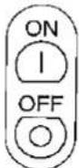

When the power is on, the LAMP REPLACEMENT indicator flashes to show the operating condition of the lamp.
Green: Lamp is ready Flashing green: Warming up Red: Change bulb
3. Turn on the POWER.
Press the POWER ON/OFF button on the projector or the POWER ON button on the remote control.
- When the power is turned off by pressing the POWER ON/OFF button, the POWER indicator will not turn off until the fan has stopped running.
- See page 28, "Lamp/Maintenance Indicators" for details.
Notes:
- When the POWER indicator is not lit, the remote control cannot be used to operate the projector.
- The flashing green LAMP REPLACEMENT indicator indicates that the lamp is warming up. Wait until the indicator stops flashing before operating the projector.
- If the power is turned on immediately after it has been turned off, it may take a short while before the lamp turns on. (During this period the LAMP REPLACEMENT indicator flashes.)
- After the projector is unpacked and turned on for the first time, a slight odour may be emitted from the exhaust fan. This odour will soon disappear with use.
Caution:
- Be sure to take off the lens cap before operation of the projector. Do not place the lens cap on the lens during operation. The lens cap may become extremely hot.
4
On-Screen Display
5

flowchart
graph TD
    A["RGB1\n1024×768\n7.5 Hz"] --> B["RGB2\n1024×768\n7.5 Hz"]
    C["COMPUTER RGB1"] --> A
    D["COMPUTER RGB2"] --> B
    E["RGB1\n1024×768\n7.5 Hz"] --> F["RGB1\n800×690\n6.0 Hz"]
    G["Mac"] --> H["RGB1\n832×624"]
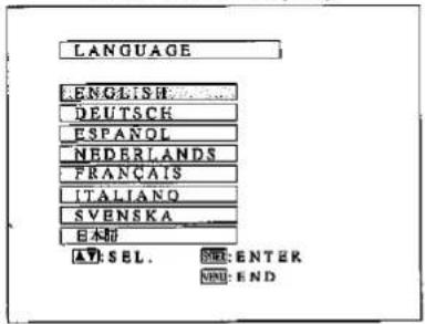
4. Select one of eight ON-SCREEN DISPLAY languages.
You can return to the previous screen by selecting the uppermost item (turquoise) with the ADJUSTMENT ▼/▲ buttons (in this case, LANGUAGE) and then pressing the ENTER button.
The on-screen display is set to English at the factory. The language for the unit's ON-SCREEN DISPLAY can be set to English, German, Spanish, Dutch, French, Italian, Swedish or Japanese.
Setting the ON-SCREEN DISPLAY language
- Press the MENU button. The menu will appear on the screen.
- Press the ADJUSTMENT ▼/▲ buttons to highlight the "LANGUAGE" item yellow. Then press the ENTER button to display the language menu.
- Press the ADJUSTMENT ▼/▲ buttons to highlight the desired language yellow. Then press the ENTER button to set the language. The ON-SCREEN DISPLAY is now programmed to display in the language chosen.
5. Select input.
Press the INPUT SELECT button on the projector to switch the picture input. When you press the button, the current input mode is displayed for about 4 seconds. If you press the button again while the input mode is displayed, the mode changes as shown on the left. Confirm the selected input terminal and press the INPUT SELECT button.
Notes:
- The input can be selected directly using the DATA 1 and DATA 2 buttons on the remote control. (When DATA 1 or DATA 2 is selected, the RGB 1 or RGB 2 screen will appear accordingly.)
- When selecting RGB mode, the resolution being displayed will be indicated under "RGB", as shown on the left. (Refer to the second example when connecting to Mac display.)
- When no signals are being received, "NO SIGNAL" will be displayed. When receiving a signal the projector is not preset to receive, "NOT REG." will be displayed.
6
On-Screen Display

6. Press INPUT CHECK.
When the INPUT CHECK button on the remote control is pressed, the current input mode is displayed for about 4 seconds.
Note:
- The INPUT CHECK button will not function if the INPUT DISPLAY is turned off, as described on page 26.
7

7. Adjust the volume.
Press the VOLUME UP-DOWN buttons on the projector or on the remote control to adjust the volume.
MUTE
- Press the MUTE button to temporarily turn off the sound.
- Press the MUTE button once again to turn the sound back on.
8

8. To turn off the power from the projector or the remote control
- Press the POWER ON/OFF button on either the projector or the remote control. The screen on the left will appear.
- If you want to turn off the power, press the POWER ON/OFF button on either the projector or the remote control again within 4 seconds. The power is now temporarily turned off.
- If you accidentally pressed the POWER ON/OFF button and do not want to turn off the power, wait until the on-screen display disappears.

The POWER indicator will turn red and the cooling fan will run for 90 seconds, then the power will turn off, and the projector will return to STANDBY mode.
The power can be turned on again either from the projector or the remote control. When the power is turned on, the POWER indicator and LAMP REPLACEMENT indicator light green.
Note:
- When the MAIN POWER is off on the projector set, the power cannot be turned on from the remote control.
1
On-Screen Display

2

3

- This projector's picture is factory preset to standard settings. However, you can adjust it to suit your own preferences with the ADJUSTMENT buttons on the projector and the remote control.
- The adjustments can be memorised in RGB 1, RGB 2 separately.
- Four picture modes can be adjusted: "PICTURE," "BRIGHT," "RED," and "BLUE."
Adjusting the Picture
1. Use the MENU button to select the mode to be adjusted.
- When the MENU button is pressed, the MENU mode is indicated for about 30 seconds. Press the ADJUSTMENT ▼/▲ buttons to select "RGB1 ADJ.", then press the ENTER button.
2. Adjust the Picture.
- Press the ADJUSTMENT ▼/▲ buttons to highlight yellow the picture adjustment item you want to adjust.
- Press the ADJUSTMENT ◀/▶ buttons to move the "♦" mark of the selected adjustment item to the desired setting.
- The adjustment mode is displayed for about 30 seconds.
Description of Adjustment Items
| Selected item | ADJUSTMENT ▶ button | ADJUSTMENT ▶ button |
| PICTURE | For less contrast | For more contrast |
| BRIGHT | For less brightness | For more brightness |
| RED | For weaker red | For stronger red |
| BLUE | For weaker blue | For stronger blue |
| RESET | All RGB Adjustment items are returned to the factory preset settings.Note: To reset all adjustment items, select "RESET" in RGB 1 ADJ. mode and press the ENTER button. | |
3. Display only the item to adjust.
- Press the ADJUSTMENT ▼/▲ buttons to highlight yellow the picture adjustment item you want to adjust. If you press the ENTER button at this time, only the selected item will be displayed.
- Press the ADJUSTMENT ◀/▶ buttons to move the "♦" mark of the selected adjustment item to the desired setting.
- The adjustment mode is displayed for about 30 seconds.
4. Press the MENU button anytime to exit RGB ADJ.
On-Screen Display
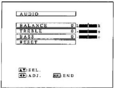
- The projector's audio is factory preset to the standard setting. However, you can adjust it to suit your own preference with the ADJUSTMENT buttons on the projector or the remote control.
-
You can adjust the "BALANCE", "TREBLE" and "BASS".
-
To return to the factory preset mode, press the ADJUSTMENT ▼/▲ buttons to select "RESET", then press the ENTER button.
- Press the MENU button to select the normal screen mode.
Adjusting the Audio
- Press the MENU button. Select "AUDIO" with the ADJUSTMENT ▼/▲ buttons. Then press the ENTER button to change to the screen indicated on the left.
- Select BALANCE, TREBLE or BASS with the ADJUSTMENT ▼/▲ buttons. Adjust the mode you want with the ADJUSTMENT ◀/▶ buttons.
- To return to the factory preset mode, press the ADJUSTMENT ▼/▲ buttons to select "RESET", then press the ENTER button.
Description of Adjustment Items
| Selected items | ADJUSTMENT ← button | ADJUSTMENT ► button |
| BALANCE | Increased audio from the left speaker | Increased audio from the right speaker |
| TREBLE | Weaker treble | Stronger treble |
| BASS | Weaker bass | Stronger bass |
Setting Up the System
Using this function, you can check the input signal and lamp usage time, and select the remote mouse.
On-Screen Display
![SYSTEM SETUP RESOLUTION 800 x 600 HOR FREQ 37.9 KHz VERT FREQ 60 Hz LAMP USAGE [234 H] REMOTE MOUSE [AT] AV: SEL. ADJ. END](/content/2026/05/992483/images/90c9844c7e2fe6fa54586114813cd930e2112f12ddf0f75528f5f4f385fe97cf.jpg)
Checking the system and lamp usage time
- Press the MENU button. Select "SYSTEM SETUP" with the ADJUSTMENT ▼/▲ buttons. Then press the ENTER button to change to the picture indicated on the left.
- The current system conditions, including the lamp usage time, will be displayed on the screen.
- Press the MENU button to select the normal screen mode.
![SYSTEM SETUP RESOLUTION 00 × 600 HOR FREQ 37.9 KHz VERT FREQ 60 Hz LAMP USAGE 1234 H REMOTE MOUSE [AT] AV: SEL. ADJ. END](/content/2026/05/992483/images/ac1efa8e84c7e47fb5e7d111d038e1ea06337a1364744f76a944dc173d10f2af.jpg)
Selecting the Remote Mouse
- Separate settings can be selected for RGB 1 and RGB 2.
- Use the INPUT SELECT buttons to select DATA 1 (RGB 1) or DATA 2 (RGB 2).
- Press the MENU button.
- Select SYSTEM SETUP with the ADJUSTMENT ▼/▲ buttons. Then press the ENTER button.
- Select "REMOTE MOUSE" and then select either "[AT]" or "[98]" with the ADJUSTMENT ◀/▶ buttons.
- Select [AT] when using IBM compatibles and Apple Macintosh series.
- Select [98] when using NEC PC98 series (for Japan).
- Press the MENU button to select the normal screen mode.

Using the Black Screen Function
This projector is equipped with a Black Screen Function. This function can be used to black out the presentation image.
- Press the BLACK SCREEN button on the projector or the remote control to display the black screen. Press the BLACK SCREEN button again to return to the presentation image.
Note:
- When "BLK SCRN DISP" is set to OFF, the On-Screen Display ("BLACK SCREEN") will not appear during black screen. See next page.
On-Screen Display
![IMAGE ADJ. ELK SCRN DISP.... IONI INPUT DISPLAY ..... [OFF] REVERSE..... [OFF] INVERT ..... [OFF] AT SEL. ADJ. .... END](/content/2026/05/992483/images/a8d004dc63471ddcc0a7737ab4fea85f0403dff368997b065f90068b666e6eaa.jpg)
Black Screen On-Screen Display override
The On-Screen Display ("BLACK SCREEN") that appears during black screen can be turned off. When "BLK SCRN DISP" is set to "OFF", the On-Screen Display will not appear during black screen.
- Press the MENU button. While the MENU screen is displayed, press the ADJUSTMENT ▼/▲ buttons to select "IMAGE ADJ." Then press the ENTER button to display the IMAGE ADJ. screen as shown. Press the ADJUSTMENT ▼/▲ buttons to select BLK SCRN DISP and press the ADJUSTMENT ◀/▶ buttons to select "ON" or "OFF".
![IMAGE ADJ. BLK SCRN DISP [OFF] INPUT DISPLAY [OFF] REVERSE [OFF] INVERT [OFF] ▲ SEL. ◀ ADJ. □ END](/content/2026/05/992483/images/d6f7493ad2190c338158f66cdf7047af89563f017e429dad8c8445779287d201.jpg)
Using the Input Mode On-Screen Display Override Function
The On-Screen Displays that appear during input select ("RGB 1,024 × 768, 75 Hz," etc.) can be turned off. Once "INPUT DISPLAY" is turned off, the On-Screen Displays will not appear even if the INPUT CHECK button on the remote control is pressed.
- Press the MENU button. While the MENU screen is displayed, press the ADJUSTMENT ▼/▲ buttons to select "IMAGE ADJ." Then press the ENTER button to display the IMAGE ADJ. screen as shown. Press the ADJUSTMENT ▼/▲ buttons to select "INPUT DISPLAY", and press ADJUSTMENT ◀/▶ buttons to select "ON" or "OFF".
- When OFF is selected, the On-Screen Display ("RGB 1,024 × 768, 75 Hz," etc.) will not be displayed during input select.
Bottom Air Filter
AIR FILTER cover

- The air filter should be cleaned every 100 hours of use. Clean the filter more often when the projector is used in a dusty or smoky location.
- Have your nearest Sharp Authorised LCD Projector Dealer or Service Centre exchange the filter (PFILD0080CEZZ) when it is no longer possible to clean it.
Cleaning and Replacing the Filter
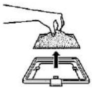
| 1 Turn OFF the MAIN POWER. | 2 Remove the FILTER COVER. | 3 Remove the AIR FILTER. |
OFF  ON POWER indicator goes off. Unplug the power cord. ON POWER indicator goes off. Unplug the power cord. | Press the tab in the direction of the arrow and lift open the filter cover. | Grasp the air filter between your fingers and lift it out of the filter cover. |
 |  | |
| 4 Clean the AIR FILTER. | 5 Replace the AIR FILTER. | 6 Replace the FILTER COVER. |
| Clean the dust off the air filter and cover with a vacuum cleaner extension hose. | Place the filter underneath the tabs on the filter frame. Return the air filter to its original position in the filter cover opening. | Insert the tab on the end of the filter cover into the filter cover opening and press the filter cover into position. |
 | 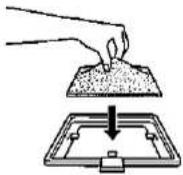 |  |
Note:
- Be sure the AIR FILTER COVER is securely installed. The power cannot be turned on unless it is correctly installed.
Lamp/Maintenance Indicators
Lamp
The lamp operating life differs, depending on the usage environment. It is recommended that the lamp be replaced after 2,000 cumulative hours of use.
- When the lamp is nearing the end of its operating life, the picture and colour quality will deteriorate. At this point, take your projector to the nearest Sharp Authorised LCD Projector Dealer or Service Centre to have the lamp replaced.
Note: The lamp usage time can be checked with the On-Screen display. (See page 25.)
- Intense light hazard. Do not attempt to look into the aperture and lens while the projector is operating.
Maintenance Indicators

LAMP REPLACEMENT TEMPERATURE indicator indicator
- The warning lights on the projector indicate problems inside the projector.
- There are two warning lights: a TEMPERATURE indicator which warns that the projector is too hot, and a LAMP REPLACEMENT indicator which lets you know when to change the lamp.
- If a problem occurs, either the TEMPERATURE indicator or the LAMP REPLACEMENT indicator will light up red, and the power will shut off. After turning off the power, follow the procedures given below.
| Warning Indicator | Symptom | Problem | Possible Solution |
| TEMPERATURE indicator | The internal temperature is abnormally high. | • Blocked air intake. | • Relocate projector to a proper location. |
| • Clogged air filter. | • Clean the filter.(See page 27.) | ||
| • Cooling fan breakdown.• Internal circuit failure. | • Take the projector to your nearest Sharp Authorised LCD Projector Dealer or Service Centre for repair. | ||
| LAMP REPLACE-MENT indicator | The lamp does not light up. | • Burnt-out lamp. | • Take the projector to your nearest Sharp Authorised LCD Projector Dealer or Service Centre for repair. |
| • Lamp circuit failure. |
Notes:
- If the TEMPERATURE indicator comes on, follow the above possible solutions and then wait until the projector has cooled down completely before turning the power back on. (At least 5 minutes.)
- When the power is turned off and then turned on again, as during a brief rest, the LAMP REPLACEMENT Indicator may be triggered, preventing the power from going on. When this happens, take the power plug out of the AC outlet and put it back in again.
Before Calling for Service
| Problem | Check |
| No picture and no sound. | The projector AC cord is not plugged into the AC wall outlet.The main power switch is not pressed.The input is wrong. (See pages 21 and 22.)Cables improperly connected to rear panel of the projector. (See pages 14, 15 and 16.)Remote control batteries have run down. (See page 7.)The optional cable for the remote control is improperly inserted.The main power of the remote control is not turned on.The remote control's MOUSE/ADJUSTMENT switch is set to MOUSE. |
| Sound is heard but no picture appears. | Cables improperly connected to rear panel of the projector. (See pages 14, 15 and 16.)The BRIGHTNESS and PICTURE adjustments are set to minimum position. (See page 23.)On-Screen Display ("BLACK SCREEN") is turned off and Black Screen function is turned on, creating a black image. (See pages 25 and 26.) |
| Picture is blurred. | Adjust the focus. (See page 9.)The projection distance is too long or too short to allow for proper focus. (See page 10.) |
| Picture appears but no sound is heard. | Cables improperly connected to rear panel of the projector. (See pages 14, 15 and 16.)Volume is set to minimum. (See page 22.) |
| An unusual sound is occasionally heard from the cabinet. | If the picture is normal, the sound is due to cabinet shrinkage caused by temperature changes. This will not affect operation or performance. |
| Maintenance indicator lights up. | Refer to "Lamp/Maintenance Indicators" on page 28. |
Analog RGB 1 and 2 Signal Input and Analog RGB Output Terminal: 15-pin mini
D-sub female connector

Computer Input
Analog
- Video input (red) 8. Earth (blue)
- Video input (green/sync on 9. Not connected
green) 10. GND - Video input (blue) 11. GND
- Reserve input 1 12. Bi-directional data
- Composite sync 13. Horizontal sync signal
- Earth (red) 14. Vertical sync signal
- Earth (green/sync on green) 15. Data clock
Mouse Input Terminal (for IBM/Mac): 9-pin D-sub female connector
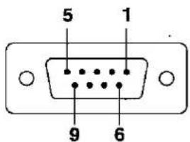
| Pin No. | Signal | Name | I/O | Reference |
| 1 | CD | Carrier Detect | Input | Connected to internal circuit |
| 2 | RD | Receive Data | Input | Connected to internal circuit |
| 3 | SD | Send Data | Output | Connected to internal circuit |
| 4 | ER | Equipment Ready | Output | Connected to internal circuit |
| 5 | SG | Signal Ground | Connected to internal circuit | |
| 6 | DR | Data Set Ready | Output | Not connected |
| 7 | RS | Request to Send | Output | Connected to internal circuit |
| 8 | CS | Clear to Send | Input | Connected to internal circuit |
| 9 | CI | Ring Indicator | Input | Connected to internal circuit |
Mouse Input Terminal (for NEC PC98 series for Japan): 9-pin mini DIN connector

| Pin No. | Signal | I/O | Reference |
| 1 | +5V | Input | Computer output |
| 2 | XA | Input | Computer output |
| 3 | XB | Input | Computer output |
| 4 | YA | Input | Computer output |
| 5 | YB | Input | Computer output |
| 6 | LEFT | Input | Computer output |
| 7 | NC | Input | Not connected |
| 8 | RIGHT | Input | Computer output |
| 9 | GND | Computer output |
RS-232C terminal: 9-pin D-sub male connector

| Pin No. | Signal | Name | I/O | Reference |
| 1 | CD | Not connected | ||
| 2 | RD | Receive Data | Input | Connected to internal circuit |
| 3 | SD | Send Data | Output | Connected to internal circuit |
| 4 | ER | Not connected | ||
| 5 | SG | Signal Ground | Connected to internal circuit | |
| 6 | DR | Data Set Ready | Output | Not connected |
| 7 | RS | Request to Send | Output | Connected to internal circuit |
| 8 | CS | Not connected | ||
| 9 | CI | Not connected |
1. PC control
A personal computer can be used to control the projector by connecting the supplied computer control cable to the PC CONTROL 1 terminal on the projector and an RS-232C cable (cross type) (not supplied) to the computer, and then connecting the RS-232C cable to the computer control cable. (RS-232C does not function when connected to PC CONTROL 2. See page 14 for connection.)
2. Communication conditions
Set the serial port settings of the computer to match that of the table below.
Signal format: Conforms to RS-232C standard.
Baud rate: 9,600 bps
Data length: 8 bits
Parity bit: NON
Stop bit: 1 bit
Flow control: None
3. Basic format
Commands from the computer are sent in the following order: command, parameter, and return code. After the unit processes the command from the computer, it sends a response code to the computer.
Command format

Response code format
Normal response

Problem response (communication error or incorrect command)

When more than one code is being sent, send each command only after the OK response code for the previous command from the unit is verified.
Note:
- Using the computer control function of the unit, the liquid crystal projector conditions cannot be read to the computer. Therefore, confirm the conditions by transmitting the display commands for each adjustment menu and checking the conditions with the On-Screen Display. If the unit receives a command other than a menu display command, it will execute the command without displaying the On-Screen Display.
4. Commands
| CONTROL ITEM | COMMAND | PARAMETER | CONTROL CONTENTS | ||||||
| C1 | C2 | C3 | C4 | P1 | P2 | P3 | P4 | ||
| POWER SETTING | P | O | W | R | - | - | - | 0 | POWER OFF |
| P | O | W | R | - | - | - | 1 | POWER ON | |
| INPUT SWITCHING | I | R | G | B | - | - | - | 1 | RGB 1 |
| I | R | G | B | - | - | - | 2 | RGB 2 | |
| INPUT CHECK | I | C | H | K | - | - | - | 0 | INPUT CHECK |
| LANGUAGE SELECTION | M | E | L | A | - | - | - | 1 | ENGLISH |
| M | E | L | A | - | - | - | 2 | DEUTSCH | |
| M | E | L | A | - | - | - | 3 | ESPANOL | |
| M | E | L | A | - | - | - | 4 | NEDERLANDS | |
| M | E | L | A | - | - | - | 5 | FRANCAIS | |
| M | E | L | A | - | - | - | 6 | ITALIANO | |
| M | E | L | A | - | - | - | 7 | SVENSKA | |
| M | E | L | A | - | - | - | 8 | JAPANESE | |
Note:
- If a dash appears in the parameter column, enter a space. If an asterisk appears, enter a value in the range indicated in brackets under CONTROL CONTENTS. See the example on the next page.
| CONTROL ITEM | COMMAND | PARAMETER | CONTROL CONTENTS | ||||||
| C1 | C2 | C3 | C4 | P1 | P2 | P3 | P4 | ||
| VOLUME ADJUSTMENT | V | O | L | A | - | - | * | * | VOLUME (0 - 60) |
| M | U | T | E | - | - | - | 0 | MUTE OFF | |
| M | U | T | E | - | - | - | 1 | MUTE ON | |
| AUDIO ADJUSTMENT | A | A | B | L | - | * | * | * | BALANCE (-30 - +30) |
| A | A | T | E | - | * | * | * | TREBLE (-30 - +30) | |
| A | A | B | A | - | * | * | * | BASS (-30 - +30) | |
| A | A | R | E | - | - | - | 0 | AUDIO DISPLAY | |
| A | A | R | E | - | - | - | 1 | RESET | |
| RGB 1 ADJUSTMENT | R | A | P | I | - | * | * | * | PICTURE (-30 - +30) |
| R | A | B | R | - | * | * | * | BRIGHT (-30 - +30) | |
| R | A | R | D | - | * | * | * | RED (-30 - +30) | |
| R | A | B | E | - | * | * | * | BLUE (-30 - +30) | |
| R | A | R | E | - | - | - | 0 | RGB DISPLAY | |
| R | A | R | E | - | - | - | 1 | RESET | |
| RGB 2 ADJUSTMENT | R | B | P | I | - | * | * | * | PICTURE (-30 - +30) |
| R | B | B | R | - | * | * | * | BRIGHT (-30 - +30) | |
| R | B | R | D | - | * | * | * | RED (-30 - +30) | |
| R | B | B | E | - | * | * | * | BLUE (-30 - +30) | |
| R | B | R | E | - | - | - | 0 | RGB DISPLAY | |
| R | B | R | E | - | - | - | 1 | RESET | |
| RGB INPUT ADJUSTMENT | I | N | C | L | - | * | * | * | CLOCK (-60 - +60) |
| I | N | P | H | - | * | * | * | PHASE (-60 - +60) | |
| I | A | H | P | - | * | * | * | H-POS (-60 - +60) | |
| I | A | V | P | - | * | * | * | V-POS (-30 - +30) | |
| I | A | R | E | - | - | - | 0 | RGB INPUT DISPLAY | |
| I | A | R | E | - | - | - | 1 | RESET | |
| SCREEN SETTING | I | M | B | K | - | - | - | 0 | BLACK SCREEN OFF |
| I | M | B | K | - | - | - | 1 | BLACK SCREEN ON | |
| I | M | D | I | - | - | - | 0 | INPUT DISPLAY OFF | |
| I | M | D | I | - | - | - | 1 | INPUT DISPLAY ON | |
| I | M | R | E | - | - | - | 0 | REVERSE OFF | |
| I | M | R | E | - | - | - | 1 | REVERSE ON | |
| I | M | I | N | - | - | - | 0 | INVERT OFF | |
| I | M | I | N | - | - | - | 1 | INVERT ON | |
| ON-SCREEN DISPLAY SETTING | I | M | B | O | - | - | - | 0 | BLACK SCREEN DISPLAY OFF |
| I | M | B | O | - | - | - | 1 | BLACK SCREEN DISPLAY ON | |
| MOUSE ADJUSTMENT | R | E | M | O | - | - | - | 1 | REMOTE MOUSE AT |
| R | E | M | O | - | - | - | 2 | REMOTE MOUSE 98 | |
| SCREEN MODE MEMORY | M | E | M | A | - | - | - | 0 | MEMORY RELEASE |
| M | E | M | A | - | - | - | * | MEMORY SELECTION (1 - 7) | |
Note:
- RGB INPUT ADJUSTMENT can only be set in the displayed computer mode.
Example:
When BRIGHT of RGB 1 IMAGE ADJUSTMENT is set to -10.

1. Specifications of wired remote control input
• 3.5ø minijack
• External: +5V (1A)
- Internal: GND
2. Function and transmission codes
| No. | Control Item | System Code | Data Code | External Code | ||||||||||||
| (Function) | C1 | C2 | C3 | C4 | C5 | C6 | C7 | C8 | C9 | C10 | C11 | C12 | C13 | C14 | C15 | |
| 1 | VOLUME UP | 1 | 0 | 1 | 1 | 0 | 0 | 0 | 1 | 0 | 1 | 0 | 0 | 0 | 1 | 0 |
| 2 | VOLUME DOWN | 1 | 0 | 1 | 1 | 0 | 1 | 0 | 1 | 0 | 1 | 0 | 0 | 0 | 1 | 0 |
| 3 | POWER ON | 1 | 0 | 1 | 1 | 0 | 0 | 1 | 1 | 0 | 1 | 0 | 1 | 0 | 1 | 0 |
| 4 | POWER OFF | 1 | 0 | 1 | 1 | 0 | 0 | 1 | 1 | 0 | 1 | 0 | 0 | 1 | 1 | 0 |
| 5 | CURSOR UP ↑ | 1 | 0 | 1 | 1 | 0 | 0 | 0 | 1 | 1 | 1 | 0 | 0 | 1 | 1 | 0 |
| 6 | CURSOR DOWN ↓ | 1 | 0 | 1 | 1 | 0 | 1 | 0 | 1 | 1 | 1 | 0 | 0 | 1 | 1 | 0 |
| 7 | ADJUST UP → | 1 | 0 | 1 | 1 | 0 | 1 | 1 | 1 | 1 | 0 | 0 | 1 | 0 | 1 | 0 |
| 8 | ADJUST DOWN ← | 1 | 0 | 1 | 1 | 0 | 0 | 0 | 0 | 0 | 1 | 0 | 1 | 0 | 1 | 0 |
| 9 | MUTE | 1 | 0 | 1 | 1 | 0 | 1 | 1 | 1 | 0 | 1 | 0 | 0 | 0 | 1 | 0 |
| 10 | MENU | 1 | 0 | 1 | 1 | 0 | 0 | 0 | 1 | 0 | 0 | 0 | 1 | 1 | 1 | 0 |
| 11 | RGS1 | 1 | 0 | 1 | 1 | 0 | 1 | 0 | 1 | 0 | 1 | 1 | 0 | 0 | 1 | 0 |
| 12 | RGS 2 | 1 | 0 | 1 | 1 | 0 | 0 | 1 | 1 | 0 | 1 | 1 | 0 | 0 | 1 | 0 |
| 13 | ENTER | 1 | 0 | 1 | 1 | 0 | 1 | 1 | 1 | 0 | 1 | 0 | 1 | 0 | 1 | 0 |
| 14 | INPUT CHECK | 1 | 0 | 1 | 1 | 0 | 1 | 1 | 0 | 1 | 1 | 0 | 0 | 0 | 1 | 0 |
| 15 | BLACK SCREEN | 1 | 0 | 1 | 1 | 0 | 1 | 0 | 0 | 1 | 0 | 1 | 1 | 0 | 1 | 0 |
Note:
- To operate the MOUSE, L-CLICK and R-CLICK functions through the wired remote control input, connect the cable from the wired remote control (supplied) terminal on the projector to the remote control. The codes for these functions are complex and are, therefore, not listed here.
Wired remote control function code
- System codes C1 to C5 are fixed at "10110".
- Codes C14 and C15 are reverse confirmation bits, with "10" indicating "Front" and "01" indicating "Rear".
3. Sharp remote control signal format
1. Transmission format
a. 15-bit format

2. Wave form of output signal
• Output using Pulse Position Modulation

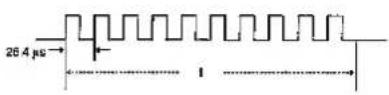
• t = 264 μs
- To = 1.05 ms
• T1 = 2.10 ms
- Pulse carrier frequency = 455/12 kHz
• Duty ratio = 1:1
3. Transmission control code
a. 15 bit
| D1 | C2 | C3 | C4 | C5 | C6 | C7 | C8 | C9 | C10 | C11 | C12 | C13 | C14 | C15 |
| System Address | Function Key Data Bit | Data Expansion | Mealt | Data Destination | ||||||||||
| D to D Common Data Bit | Reverse In D | |||||||||||||
b. Example of Reverse D to
| D1 | 02 | 03 | 04 | 05 | 06 | 07 | 08 | 09 | C10 | C11 | C12 | C13 | C14 | C15 |
| 1 | 0 | 1 | 1 | 0 | 1 | 0 | 0 | 0 | 0 | 0 | 0 | 0 | 1 | 0 |
| Product Type | LCD Projector |
| Model | XG-NV33XE |
| Display method | LCD panel × 3, RGB optical shutter method |
| LCD panel | Panel size: 33.3 mm (1.3") (20.0 [H] × 26.6 [W] mm) |
| Display method: Translucent TN liquid crystal panel | |
| Drive method: TFT (Thin Film Transistor) Active Matrix panel | |
| No. of dots: 786,432 dots (1,024 [H] × 768 [V]) | |
| Lens | 1-1.6 zoom lens, F2.5 to 3.6, f = 47 to 76 mm |
| Projection lamp | 120 W UHP lamp |
| Contrast ratio | 200:1 |
| Audio output | 2 W + 2 W (stereo) |
| Computer RGB input signal | Video signal |
| 15-PIN MINI D-SUB CONNECTOR (RGB 1, 2): | |
| RGB separate/composite sync/sync on green type analog input: | |
| 0-0.7 Vp-p, positive, 75 Ω terminated | |
| STEREO MINIJACK: | |
| AUDIO, 0.5 Vrms, more than 22 kΩ (stereo) | |
| HORIZONTAL SYNC. SIGNAL: | |
| TTL level (positive/negative) or composite sync | |
| VERTICAL SYNC. SIGNAL: | |
| Same as above | |
| Computer Control Cable (Supplied) | |
| RS-232C input terminal | 9-pin D-sub male connector for controlling personal computer |
| Mouse input terminal (for IBM/Mac) | 9-pin D-sub female connector for wireless mouse |
| Mouse input terminal (for PC98) | 9-pin mini DIN connector for wireless mouse |
| Speaker system | 2.8" × 1.6" (7 × 4 cm) oval × 2 |
| Rated voltage | AC 110-120/200-240 V |
| Input current | 1.8 A/1.0 A |
| Rated frequency | 50/60 Hz |
| Power consumption | 226 W |
| Standby consumption | 12 W |
| Operating temperature | +5°C to +40°C |
| Storage temperature | -20°C to +60°C |
| Cabinet | Plastic |
| I/R Carrier frequency | 40 kHz |
| Laser Pointer of Remote Control | Wave length |
| 670 nm | |
| Max. output | |
| 1 mW | |
| Class II Laser Product | |
| Dimensions (W × D × H) | 261 × 329 × 137 mm (main body only) |
| 266 × 399 × 155 mm (including lens, adjuster legs and projecting parts) | |
| Weight | 6.6 kg |
| Supplied accessories | Remote control unit, Four AA batteries, Extra air filter, RGB signal cable (3 m), Macintosh adaptor, Computer control cable (1 m), Mouse control cable for IBM PS/2 (15 cm), Mouse control cable for Mac (15 cm), Mouse control cable (3 m), Computer audio cable, AC cord, Lens cap (installed) |
| Replacement parts | Remote control (RRMCG1415CESA), Air filter (PFILD0080CEZZ), RGB signal cable (QCNW-5050CEZZ), Macintosh adaptor (QPLGJ1512CEZZ), Mouse control cable for IBM PS/2 (QCNW-4754CEZZ), Mouse control cable for Mac (QCNW-4755CEZZ), Mouse control cable (QCNW-4620CEZZ), Computer control cable (CTANZ0711CE01), Computer audio cable (QCNW-4870CEZZ), AC cord |
Our projector uses LCD (Liquid Crystal Display) panels. These very sophisticated panels contain 786,432 pixels (× RGB) TFTs (Thin Film Transistors).
As with any high technology electronic equipment such as large screen TVs, video systems and/or video cameras, there are certain acceptable tolerances that the equipment must conform to. This unit has some inactive TFTs within acceptable tolerances, which may result in illuminated or inactive dots on the picture screen.
This will not affect the picture quality or the life expectancy of the unit.
Specifications are subject to change without notice.
Rear View

natural_image
Line drawing of a rectangular device with internal grid and two circular switches on top (no text or symbols)Top View

natural_image
Line drawing of a cylindrical mechanical device with handle and side ports (no text or symbols)Side View
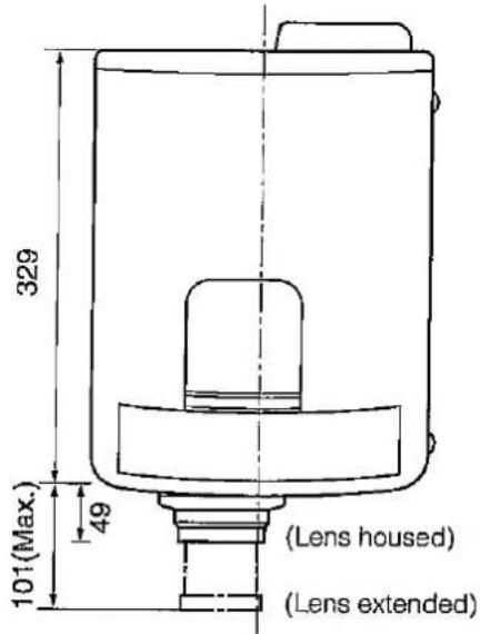
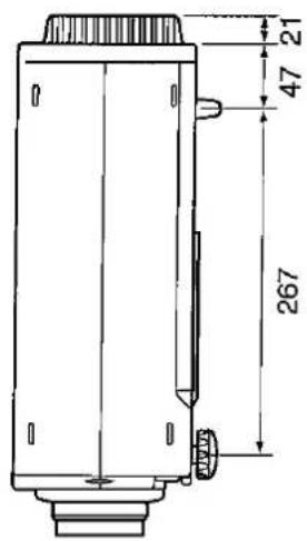

Front View

natural_image
Technical line drawing of a mechanical component with no visible text or symbolsBottom View
[Units: mm]
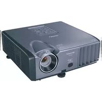
- DANGER:
- IMPORTANT:
- IMPORTANT
- Important Information
- WARNING:
- CAUTION:
- Contents
- ATTENTION: Please read all of these instructions before you operate your LCD Projector for the first time. Save these instructions for future reference.
- Cautions Concerning the Laser Pointer
- LASEROVÉ ZÁŘENÍ
- Notes on Operation
- About the Temperature Monitor Function:
- Outstanding Features
- DIRECT COMPUTER COMPATIBILITY
- HIGH PICTURE QUALITY
- INTELLIGENT COMPRESSION
- VERSATILE REMOTE CONTROL
- FLEXIBLE USE
- BUILT-IN STEREO SPEAKERS
- USE WITH "PLUG AND PLAY"
- Cautions:
- Note:
- Notes:
- Operating the Wireless Mouse Remote Control
- Using the remote control in a dark room
- TOP VIEW
- Using the optional cable with the remote control
- REAR VIEW
- Inserting the batteries
- Remote control positioning
- MOUSE buttons
- LEFT-CLICK button
- RIGHT-CLICK button
- LASER POINTER button
- Using the Focus and Zoom
- Turn on the MAIN POWER.
- Turn on the POWER.
- Rotating the zoom ring (from the housed position to the wide angle position)
- Adjusting the focus
- Adjusting the zoom
- Projector Distance and Picture Size Relationship
- Distance from screen
- Height of Projector
- Using the Image Invert/Reverse Function
- Press the MENU button.
- Reversed Image Mode
- Inverted Image Mode
- Reversed Inverted Image Mode
- Press the MENU button anytime to exit IMAGE ADJ.
- How to set up the projector and screen
- Cautions: When setting up the projector
- Example of a standard setup
- Example of a reversed image setup
- Example of a ceiling-mount setup
- Adjusting the Height of the Picture
- Returning the projector to its original position
- Transporting the Projector
- Connecting the Projector (RGB 1, 2: Computer)
- "Plug and Play" Function
- Connecting to the Computer RGB Input (RGB 1, 2)/Output Terminals
- Connecting to an IBM-PC (VGA, SVGA, XGA, SXGA) Series computer—1,280 × 1,024 maximum resolution
- Connecting to a Macintosh Series Computer
- Connecting to other compatible computers
- Connecting to the COMPUTER AUDIO INPUT
- Connecting an external monitor
- Caution (Apple Macintosh):
- Examples:
- Input Signals (Recommended Timing)
- For IBM and compatibles
- Input signals:
- RGB Input Adjustments (CLOCK, PHASE, V-POS and H-POS)
- Press the MENU button anytime to exit RGB INPUT ADJ.
- Description of Adjustment Items
- CLOCK SPEED ADJUSTMENT (FAST/SLOW)
- PHASE ADJUSTMENT (UP/DOWN)
- HORIZONTAL POSITION ADJUSTMENT (LEFT/RIGHT)
- VERTICAL POSITION ADJUSTMENT (UP/DOWN)
- MODE ADJUSTMENT
- INITIAL RESET
- MEMORY SELECT
- When RGB 1 or 2 is selected.
- Computer Mode Memory Adjustments
- Press the ENTER button to select the Memory Adjustment mode.
- Press the ADJUSTMENT ◀/▶ buttons.
- Basic Operation of the Projector
- Connect the AC cord.
- Turn on the MAIN POWER.
- Turn on the POWER.
- Select one of eight ON-SCREEN DISPLAY languages.
- Setting the ON-SCREEN DISPLAY language
- Select input.
- Press INPUT CHECK.
- Adjust the volume.
- MUTE
- To turn off the power from the projector or the remote control
- Adjusting the Picture
- Use the MENU button to select the mode to be adjusted.
- Adjust the Picture.
- Display only the item to adjust.
- Press the MENU button anytime to exit RGB ADJ.
- Adjusting the Audio
- Setting Up the System
- Checking the system and lamp usage time
- Selecting the Remote Mouse
- Using the Black Screen Function
- Black Screen On-Screen Display override
- Using the Input Mode On-Screen Display Override Function
- Bottom Air Filter
- Lamp/Maintenance Indicators
- Lamp
- Maintenance Indicators
- Before Calling for Service
- Analog RGB 1 and 2 Signal Input and Analog RGB Output Terminal: 15-pin mini
- Computer Input
- Analog
- Mouse Input Terminal (for IBM/Mac): 9-pin D-sub female connector
- Mouse Input Terminal (for NEC PC98 series for Japan): 9-pin mini DIN connector
- RS-232C terminal: 9-pin D-sub male connector
- PC control
- Communication conditions
- Basic format
- Commands
- Example:
- Specifications of wired remote control input
- Function and transmission codes
- Sharp remote control signal format
- Transmission format
- Wave form of output signal
- Transmission control code
Brand : SHARP
Model : XG-NV33XE
Category : Video projector