CA-340 Nestor - Car alarm Jablotron - Free user manual and instructions
Find the device manual for free CA-340 Nestor Jablotron in PDF.


| Product Type | Car Alarm System |
| Brand | Joblotron |
| Model | CA-340 Nestor |
| Category | Vehicle Security |
| Dimensions (Main Unit) | Approx. 120 x 70 x 25 mm |
| Weight (Main Unit) | Approx. 150 g |
| Power Supply | 12V DC (Vehicle Battery) |
| Operating Voltage | 9-16V DC |
| Current Consumption (Standby) | < 20 mA |
| Remote Control Range | Up to 50 meters (line of sight) |
| Shock Sensor | Adjustable dual-zone impact sensor |
| Alarm Types | Siren, parking light flash |
| Key Features | Remote arm/disarm, passive arming, panic mode, valet mode, starter kill |
| Installation | Professional installation recommended |
| Operating Temperature | -40°C to +85°C |
| Certifications | CE, RoHS |
| Warranty | 1 year limited |
| Manual Languages | EN, FR, DE, ES, IT |
| Spare Parts Availability | Remote controls, sensors, wiring harness available |
| Repairability | Modular components replaceable |
Frequently Asked Questions - CA-340 Nestor Jablotron
User questions about CA-340 Nestor Jablotron
0 question about this device. Answer the ones you know or ask your own.
Ask a new question about this device
Download the instructions for your Car alarm in PDF format for free! Find your manual CA-340 Nestor - Jablotron and take your electronic device back in hand. On this page are published all the documents necessary for the use of your device. CA-340 Nestor by Jablotron.
USER MANUAL CA-340 Nestor Jablotron
Car alarm CA-340 "Nestor" functions, controls
The CA-340 car alarm is intended for installation inside a vehicle with a 12 or 24V power supply and negative ground. It is protected against the reversal of poles and overvoltage, the activation inputs are protected against short circuit and voltage induction.
Car alarm function overview
- A built-in shock detector with adjustable sensitivity controlled with a trimmer inside the unit. Its activation can trigger a warning (1s siren chirp), trigger an alarm or do both. If an alarm function is set, the unit uses a filter eliminating accidental shocks (e.g. caused by a heavy vehicle passing by ...). The alarm is triggered only when the first shock is followed by another within 15 seconds. If both the siren and the alarm are set, the first shock triggers a short siren chirp and the second shock (within 15 s) triggers the alarm.
- A voltage drop detector registers sudden voltage drops caused by an appliance which switches on when the alarm is armed (protection against a mechanical breach of the central locking system). The detector is blocked for 20 minutes after arming (allows the radiator cooling fan to wind down). You can also program it to remain switched off permanently if you use independent appliances in the car (heater, refrigerator).
- The car alarm is equipped with several contact sensors, whose number depends on how the alarm is connected (see below).
- Up to 8 JA-8x wireless detectors can be enrolled to the car alarm. These can be used to detect motion inside the vehicle or the breaking of windows or to guard the garage in which the vehicle is parked.
- A programmable output which can trigger the power supply to auxiliary detectors (microwave, tilt) that are activated when the alarm is armed or it can provide a signal for the controlling of a CR-11A (AUX) module.
- The immobiliser circuit can be used to immobilize the ignition, the fuel pump or the ignition circuit. When the AUTOIMO function is active, the immobiliser is activated automatically if the ignition key is switched off for more than 5 minutes. The AUTOIMO can be switched off by a remote control button.
- When an alarm is triggered, a siren is activated for 30s. When the alarm is terminated in a regular way, the siren is switched off immediately.
- The siren can also be used for the acoustic confirmation of arming and disarming (optional parameter). For other functions, see Acoustic signaling.
- When you leave your vehicle in a car servicing company for maintenance, the AUTOIMO function and the acoustic signaling can easily be temporarily disabled.
- Optical signaling of arming, disarming and alarms. The car alarm can control the direction indicators (flashers) in three optional modes.
- Boot opening. When the alarm is armed, you can use a remote control to open the car boot if its mechanism allows it. (The BLK output function must be set to control the boot)
- PANIC is a function which allows triggering a siren with a remote control both in an armed and an unarmed state (by pressing both buttons at the same time). It can also help you find your vehicle quickly in a crowded car park.
- The car alarm is equipped with a Valet button for emergency disarming. The button can also serve for the setting of optional parameters.
- The information concerning operating status of the alarm is signaled with an LED.
- The car alarm settings and parameters can be changed easily using the CA-340PRG wireless module connected to a computer.
Car alarm controls
The car alarm can be armed by locking the vehicle with the original remote control or by pressing the 🔒 key on the RC-8x remote control (depending on the means of connection).
Partial setting. When the setting key is pressed repeatedly during the exit delay (20s after the alarm setting) the shock and voltage drop detectors and wireless detectors guarding the inside of the vehicle are disabled. NOTE: this function is not available when the car alarm is connected for controlling with the original remote control without using a CAN-Bus (= AL1 input is set to confirm arming and disarming)
The car alarm can be disarmed by unlocking the vehicle with the original remote control or by pressing the key on the RC-8x remote control (depending on the means of connection).
Rearming function If the car alarm is unarmed and no sensor is activated within one minute (no one gets into the car), the alarm is armed again. If the alarm controls the central locking system, the vehicle is locked simultaneously. This function can be set by parameter 2 (REARM).
Boot opening. The car booth can be opened by pressing both remote control buttons (the availability of this function depends on the means of installation).
Alarm
When armed, the car alarm checks the DOOR contact switches, INP1, INP2, INP3 sensors where boot, bonnet or other detectors can be connected and manipulation with the ignition key. It also reacts to the activation of the integrated shock detector, voltage drop and enrolled wireless detectors. The wireless detectors can be set to a 20s entrance delay (see the detector manual). If any of the alarm sensors are activated in the period of guarding, a 30s alarm is triggered. When the alarm has finished, the car alarm remains active.
- If the car alarm is controlled with original remote controls, the currently active alarm can be terminated by unlocking the vehicle using the remote control. The car alarm is concurrently disarmed.
- When the car alarm is controlled with an RC-8x remote control, pressing the 🔒 or 🔑 keys can terminate the currently active alarm. Pressing the 🔑 key again disarms the alarm.
Emergency disarming – if the remote control gets lost or is faulty, the car alarm can be disarmed by pressing the hidden Valet button as follows:
Open the car doors (triggers an alarm), switch on the ignition key and press the Valet button. The emergency disarming can be disabled (parameter 4).
LED visual signaling
The LED indicates the alarm status as follows:
| the LED is off | - the car alarm is unarmed |
| permanently lit | - exit delay in progress |
| regular short flashes | - the car alarm is armed |
| rapid flashing | - entrance delay in progress |
| regular short fading | - AUTOIMO function activate |
When the ignition key is switched on, the LED indicates the number of enrolled RC-8x controllers.
Three alarm chirps during unarming indicate that there has been an alarm since the last setting. When you turn on the ignition key, the LED then indicates the cause of the alarm. The signaling is repeated 5 times. The number of flashes indicates the sensor which triggered the alarm:
1 flash - the door sensor (DOOR) was activated
2 flashes - the INP1 sensor was activated
3 flashes - the INP2 sensor was activated
4 flashes - the INP3 sensor was activated
5 flashes – the voltage drop sensor (an appliance was switched on)
6 flashes – shock detector alarm
7 flashes – the ignition key was switched on in an armed state
1 to 8 fadings – wireless detector (according to the order in which it is enrolled)
The cause of the last two alarms can be viewed retroactively. If you press the Valet button when the ignition key is on, the LED indicates the cause of the last alarm 10 times successively. If you press the Valet button again during the signaling, the cause of the previous alarm is also shown ten times. The indication is terminated when the ignition key is switched off.
Acoustic signaling
Setting: 1 chirp * Partial arming: two quick chirps Unarming: 2 chirps * Unarming after an alarm: 3 chirps
can be disabled by setting partial acoustic signaling
Fault signaling:
- When armed, the car alarm tests the sensors for approx. 6s. If any of the sensors is activated during this period of time (e.g. due to an improperly closed door) it is signaled with 4 quick chirps. The alarm is armed but the sensor which remained active is disconnected (it can react only when it is deactivated again—the door is closed, etc.)
- If a CA-340 SIR wireless antenna is installed, then the activation of the engine compartment switch is signaled with 5 quick chirps.
- If the alarm emits 6 quick chirps, it signals that the battery in one of the wireless detectors is low. When the ignition key is switched on, it is possible to find out which detector it is according to the fading of the LED (1 to 8 – pursuant to the order in which the detectors are enrolled).
Temporary silent control and disabling of the AUTOIMO
If it is necessary due to any reason (putting the vehicle in a car servicing company for maintenance, holiday) the acoustic signaling and AUTOIMO function can easily be temporarily disabled by switching off the ignition key while holding the Valet button. It is confirmed with an acoustic signal. These functions can be enabled again in the same way, on condition that they are not disabled permanently in the settings.
Maintenance
The device does not require any special maintenance. We recommend regular inspections of door and bonnet contact functioning, or possibly of the auxiliary detectors. This inspection should be performed by a professional installer with whom regular annual inspections should be arranged.
We recommend having the car alarm installed by an authorized service company. Improper installation can result in damage to your vehicle. The car alarm manufacturer shall not be held responsible for any damage caused by incorrect installation or misuse of the product.
The immobilizer relay contact of car alarm is connected only in disarmed mode and if the ignition is on. Do not block circuits that are under voltage while the ignition is off. It could cause a serious damage of the vehicle.
The SIR output switches power supply. If is installation with 24V power supply there must be used the siren type SA-606-24V or other type for 24V instead of standard packaged siren.
First, disconnect the car battery. Nobody should be inside a vehicle equipped with airbags during the manipulation of the battery (disconnecting, connecting). Keep in mind that some devices equipped with a memory can be erased when the battery is disconnected.
Attach the newly installed wires to the original bundles. When making connections use a crimping tool fit for this purpose. If possible, avoid drilling into metal parts during installation. If you have to drill any holes, make sure you avoid damaging any other parts of the vehicle. The basic car alarm unit is suitable for installation in the passenger compartment (the best position would be under the dashboard).
The car alarm functions can be set comfortably using the CA-340PRG wireless programming module.
Car alarm connector description

Wire functions
GND black – connect to the negative pole of the power supply.
+12V / +24V red – connect to the positive pole of the power supply. Protected with a built-in fuse.
SIR yellow - siren output, the maximum current is 1.5A. If there is a short circuit or current overload, the output is disconnected. Reconnection is possible only with another activation of the output.
BLK 2x violet – direction indicator relay or boot bounce control.
IMO 2x brown – immobilizer relay contact
ULK white and blue – central locking alarm input / output – unlocking signal. As an input it reacts to the connection or disconnection of GND. If it has an output function, it reacts to the connection of GND.
LCK black and white – central locking alarm input / output – locking signal. As an input it reacts to the connection or disconnection of GND. If it has an output function, it reacts to the connection of GND.
LED green – positive output of the LED.
VAL green and black – connection of the Valet setting button
AUX pink – output providing power supply to auxiliary detectors (12V) or CR-11 module control output.
Its function is set with programming parameter 11 (see the table below).
KEY blue – ignition key input, alarm input. Reacts to +12/24V induction.
DOOR grey - door switch input, reacts to the connection to GND (it has optional activation polarity if set for RC-8x remote control).
INP1 white - alarm input (reacts to the connection to GND) or direction indicator signal input (reacts to the disconnection from GND). Its function is determined by the connection and setting as mentioned below.
INP2 yellow and white – alarm input, optional activation polarity, optional reaction.
INP3 white and green – alarm input, reacts to the connection to GND.
Programmable functions
The car alarm offers optional function parameters (see the table) which can be set in the programming mode. Entering the programming mode:
-
Press the Valet button and hold it for 4 – 6 s and then switch on the ignition key. Entering the programming mode is confirmed with two long chirps of the siren. The alarm concurrently transmits its "enrolment code".
-
It is then necessary to select between optional parameter setting and the enrolment of wireless detectors. Press the Valet button to enter optional parameter setting and then follow section 6. If you want to enter the wireless device enrolment mode, switch off the ignition key (within 2 s). Then follow Section 3.
-
Now you can enroll the RC-8x remote controls * (max. 4). The remote controls
can be enrolled by pressing both and keys simultaneously for approx. 3 s. The enrolment is confirmed with a siren chirp. All remote controls can be erased by switching off the ignition key for a short time. Press the Valet button to continue
to internal detector enrolment. Switching off the ignition key for more than 3 s terminates the programming mode (the siren emits two short chirps).
- Enrolment of detectors installed in the vehicle* (internal ones). This group includes detectors guarding the interior of the vehicle (not if the alarm is armed partially). If a remote control is enrolled in this group, it can be used to trigger a PANIC alarm. Internal detectors can be erased by switching off the ignition key for a short time. Press the Valet button to continue to external detector enrolment. Switching off the ignition key for more than 3 s terminates the programming mode (the siren emits two short chirps).
- Enrolment of external detectors* (guarding of a garage). Detectors in this group are active both during partial and complete arming. The JA-80A wireless siren can also be enrolled here. External detectors can be erased by switching off the ignition key for a short time. A maximum of 8 detectors can be enrolled. Press the Valet button to continue to optional parameter setting pursuant to the following article. Switching off the ignition key for more than 3s terminates the programming mode (the siren emits two short chirps).
- Now you can set the first parameter. The parameter setting is signaled with an LED (on / off). Changes can be performed by switching off the ignition key for a short time (no longer than 3 s).
- Press the Valet button to go on to the next parameter. The number of siren chirps indicates the parameter which you are currently setting. The tenth parameter is signaled with a long siren chirp, while from the eleventh parameter onwards the siren signals only parameter units (e.g. 11=1 chirp, etc).
- Switching off the ignition key for more than 3s terminates the programming mode without saving (the siren emits two short chirps).
- To save your settings you have to go through all 18 parameters. When the last parameter has been set, press the Valet button once more. The termination of the mode is confirmed with a long chirp of the siren.
* PLEASE NOTE! Enrolling the first device erases all previously enrolled devices in the given group (you should therefore gradually enroll all devices which you want to use)
Wireless components of the OASIS system
- It is possible to use motion detectors, glass break detectors and magnetic detectors (JA-85P, JA-85B, JA-81M) to guard the vehicle interior or a garage. The maximum of 8 detectors can be enrolled. A low battery in a detector is signaled with its LED, the car alarm LED and also with a siren when the system is armed.
- The CA-340SIR wireless siren with the bonnet contact input can be installed in the engine compartment, so that it is not necessary to install the wires in the vehicle interior.
- The alarm can also be signaled via JA-80A and JA-80L internal wireless sirens. (when using JA-80A you have to take into account that there is a delay depending on the jumper setting in the siren)
- The alarm can be enrolled to the OASIS electronic home security system as a detector.
- Wireless detectors have a tamper contact. Manipulation with detectors (when changing batteries) is thus possible only if the ignition key is switched on and the car alarm is unarmed. Otherwise alarm is triggered.
For more detailed information concerning wireless components for the guarding of objects go to www.jablotron.com.
Technical specifications
| Power supply voltage | 12/24 V (9 – 32)V DC |
| Stand-by current consumption | 11 mA |
| TRX frequency switching range | 1 RF channel 868,5 MHz |
| Transmitter power | < 25 mW |
| Operational temperature range | -40 to +85°C |
| SIR output | +12V (24V), max. load 1.5 A |
| Alarm duration | 30 s |
| Immobilizer circuit current | 8 A cont., 12 A intermittent |
| BLK relay circuit current | 8 A cont., 12 A intermittent |
| PGM output current | 25 mA |
| ULK/LCK output current | 200 mA |
| Enclosure (EN 60529) | IP30 |
| Dimensions | 118 x 80 x 35 mm |
| Complies with: | |
| ECE regulation | No. 97.01 |
| RTTE directive | 1999/5/EC |
| Safety | EN 60950-1 |
| EMC | ISO 7637, ISO 11452, CISPR-12 |
| Radio interference | ETSI EN 300 220 |
| Can be operated according to | ERC REC 70-03 |

97 R A-01 5862

JABLOTRON ALARMS Inc. hereby declares that the CA-340 is in compliance with the essential requirements and other relevant provisions of ECE Regulation No. 97.01, Directive 1999/5/EC and 1995/56/EC The original of the conformity assessment can be found at www.jablotron.com. Technical Support section
Note: Although this product does not contain any harmful materials we suggest you return the product to the dealer or directly to the producer after use.
flowchart
graph TD
    A["CA-340"] --> B["JA-85P (movement)"]
    A --> C["JA-85B (glass break)"]
    A --> D["max. 8x"]
    A --> E["max. 4x RC-8x"]
    A --> F["pink"]
    A --> G["AUX"]
    A --> H["CR-11A"]
    H --> I["+12 V"]
    H --> J["±90°"]
    H --> K["tilt detector"]
    A --> L["electric windows"]
    L --> M["central locking"]
    M --> N["LOCK"]
    M --> O["UNLOCK"]
    N --> P["white-black"]
    O --> Q["white-blue"]
    R["Ignition key ("15")"] --> S["blue"]
    T["Door switches"] --> U["grey"]
    V["INP1 - alarm input"] --> W["white"]
    X["INP2 - alarm input"] --> Y["yellow-white"]
    Z["INP3 - alarm input"] --> AA["green-white"]
    AB["Immobilization (max. 12A)"] --> AC["2x brown"]
    AD["LED"] --> AE["Green"]
    AD --> AF["Black"]
    AD --> AG["Green-black"]
    AD --> AH["Black"]
    AI["Violet"] --> AJ["Fuse15A"]
    AK["R"] --> AL["L Turn lights"]
    AM["Siren"] --> AN["Siren"]
    AO["violet"] --> AP["violet"]
    AQ["12 / 24 V Battery"] --> AR["Battery"]
 |
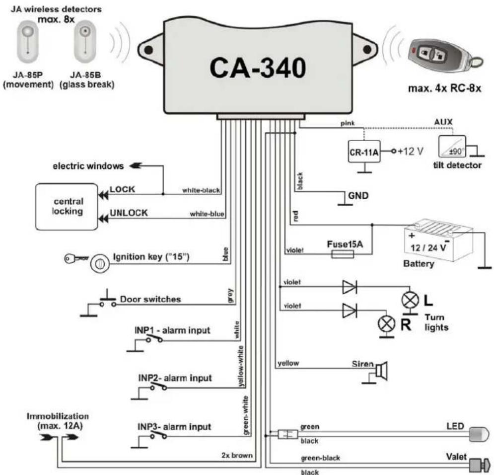
Connection without a CAN-Bus converter, controlling with RC-8x remote controls
Connection pursuant to Fig 1, setting pursuant to profile 1. The values shown in the table in bold letters are the default ones. The profile is defined by parameter 1 setting.
A description of individual wire functions is available on page 2.
Vehicle status information is obtained via direct connection to the ignition circuit and door, bonnet and boot switches. A thus connected car alarm can control the central locking of the vehicle. It is possible to set an extended locking impulse which can be used to close the windows of certain vehicle types after arming.
Connection with a CAN-Bus converter, controlling with RC-8x remote controls
Setting pursuant to profile 1.
Information about the vehicle status (ignition key, door, bonnet, boot) is obtained via a CAN-Bus converter.
NOTE: The converter cannot be used to control the central locking of the vehicle.
Direction indicator (flasher) connection
Optical signaling of arming, disarming and alarm is possible in three modes.
- Direct connection to the light bulb circuits. Connection pursuant to Fig. 1. The power supply is directed to the relay contact via a 15A fuse. The contact output is forked using diodes and it is then connected to the left and right direction indicator light.
-
Connection via a warning light switch, pursuant to Fig. 2. When this option is selected, the INP1 input always has a feedback function (counting the flashes) and it has to be connected to a direction indicator light power circuit. It is therefore not possible to use this optical signaling when the alarm is controlled with the original remote control without using a CAN-Bus converter (this option is superior to the setting parameter 12 of profile 2, INP1 then has no function for confirmation of disarming or alarm input). The flashing can then be controlled with the following options:
-
„switch“ – the relay is switched if the direction indicator lights should flash
- „button“ - the relay gives an impulse to begin and finish flashing

flowchart
graph TD
    A["CA-340"] --> B["MCB-01"]
    A --> C["original remote controller"]
    A --> D["unknown"]
    A --> E["red"]
    A --> F["pink"]
    A --> G["AUX"]
    A --> H["CR-11A"]
    H --> I["+12 V"]
    I --> J["+90° tilt detector"]
    J --> K["Battery"]
    K --> L["Hazard light button"]
    L --> M["violet"]
    L --> N["violet"]
    L --> O["yellow"]
    L --> P["Siren"]
    Q["CAN-L"] --> R["UNLOCK white-blue"]
    S["CAN-H"] --> T["LOCK white-black"]
    U["INP3-bonnet green-white"] --> V["INP2-boot yellow-white"]
    W["Door switches grey"] --> X["Ignition key ("15") blue"]
    Y["Immobilization max. 12A"] --> Z["INP1 -Turn lights white"]
    AA["LED"] --> AB["green black"]
    AA --> AC["green-black"]
    AA --> AD["black"]
    AE["Valet"] --> AF["Blue"]
    AG["Max. 8x"] --> AH["JA-85P movement"]
    AI["Max. 4x RC-8x"] --> AJ["Max. 4x RC-8x"]
Connection with a CAN-Bus converter, controlling with the original remote controls
Connection pursuant to Fig 2, settings pursuant to profile 2. The values shown in the table in bold letters are the default ones. The profile is defined by parameter 1 setting.
A thus connected car alarm obtains vehicle status information (ignition key, vehicle locking and unlocking, door, bonnet and boot opening) via the CAN-Bus converter. The INP1 input can be used as an alarm input for auxiliary detectors. If the vehicle is not equipped with e.g. a bonnet switch, it is possible to disconnect the corresponding input from the MCB-01 converter and use it for direct connection of an additionally installed switch. If RC-8x controllers are enrolled in this control mode, they can be used to disarm and arm the alarm, but they will not unlock or lock the vehicle. If necessary, the vehicle unlocking and locking impulses can be generated using the CR-11A module.
Connection without a CAN-Bus converter, controlling with original remote controls
The principle is similar to that in Fig 2, setting pursuant to profile 2, the vehicle status information is obtained via a direct connection to the central locking of the vehicle, switches and ignition circuit. In this case the INP1 input is used to confirm arming and disarming (direction indicator lights flashing).
When you use the direction indicator lights to confirm unarming, they cannot concurrently be controlled with the car alarm.
A thus connected car alarm monitors the status of the central locking. If the vehicle is locked and the direction indicator lights flash concurrently (pursuant to parameter 13 setting), the car alarm is armed. If the vehicle is unlocked and the direction indicator lights flash concurrently, the car alarm is unarmed. The flashing of the direction indicator lights is always required for the disarming of the car alarm. If, therefore, the doors are unlocked with a lock (not confirmed with direction indicator lights), the car alarm is not unarmed and an alarm is triggered. If RC-8x controllers are enrolled in this control mode, they can be used to disarm and arm the alarm, but they will not unlock or lock the vehicle. If necessary, the vehicle unlocking and locking impulses can be generated using the CR-11A module.
JABLOTRON
JABLOTRON ALARMS a.s.
Pod Skalkou 4567/33
46601 Jablonec nad Nisou
Tel.: 483 559 911
Fax: 483 559 993
| Profile 2 – controlling with an original remote control | ||||||||
| parameter | * = LED on | O= LED off | ||||||
| 1 | Central lock control | ○ | no, the alarm is controlled with ULK and LCK inputs ( this setting defines the function of parameters 12,13,14) | |||||
| 2 | Rearm | * | Yes | ○ | No | |||
| 3 | Autoimo | * | Yes | ○ | No | |||
| 4 | Disarming with the Valet button | * | Yes | ○ | No | |||
| 5 | Acoustic signaling | * | Yes | ○ | partial | |||
| 6 | Increased volume of signaling | * | Yes | ○ | No | |||
| 7 | Open door test | * | Yes | ○ | No | |||
| 8 | Voltage detector | * | Yes | ○ | No | |||
| 9 | Shock warning | * | Yes | ○ | No | |||
| 10 | Shock alarm | * | Yes | ○ | No | |||
| 11 | AUX output function | * | EXT sensor power supply | ○ | AUX bus output | |||
| 12 | INP1 input function | * | Alarm input | ○ | Disarming / arming confirmation | |||
| 13 | Arming confirmation | * | Yes | ○ | No | |||
| 14 | ULK and LCK input activation | * | Ground | ○ | Ground disconnection | |||
| 15 | INP2 input activation | * | Ground | ○ | Ground disconnection | |||
| 16 | INP2 input reaction | * | Alarm | ○ | Warning | |||
| 17 | BLK output reaction | ○ | Boot control | ○ | Direct direction indicator control | * | Direction indicator control switch | * |
| 18 | ○ | * | ○ | * | ||||
- Car alarm CA-340 "Nestor" functions, controls
- Car alarm function overview
- Car alarm controls
- Alarm
- LED visual signaling
- Acoustic signaling
- Fault signaling:
- Temporary silent control and disabling of the AUTOIMO
- Maintenance
- Wire functions
- Programmable functions
- Wireless components of the OASIS system
- Connection without a CAN-Bus converter, controlling with RC-8x remote controls
- Connection with a CAN-Bus converter, controlling with RC-8x remote controls
- Direction indicator (flasher) connection
- Connection with a CAN-Bus converter, controlling with the original remote controls
- Connection without a CAN-Bus converter, controlling with original remote controls
- JABLOTRON
Brand : Jablotron
Model : CA-340 Nestor
Category : Car alarm