JA-83K - Surveillance Camera Jablotron - Free user manual and instructions
Find the device manual for free JA-83K Jablotron in PDF.


| Product Type | Surveillance Camera |
| Brand | Joblotron |
| Model | JA-83K |
| Resolution | 1080p Full HD |
| Night Vision | Up to 30 meters with IR LEDs |
| Field of View | 90 degrees |
| Motion Detection | Yes, with push notifications |
| Storage | MicroSD card up to 128 GB (not included) |
| Connectivity | Wi-Fi 2.4 GHz, Ethernet (RJ45) |
| Power Supply | DC 12V / 1A (adapter included) |
| Dimensions | 120 x 70 x 70 mm |
| Weight | 350 g |
| Weatherproof Rating | IP66 |
| Audio | Two-way audio with built-in microphone and speaker |
| Smart Integration | Compatible with Alexa and Google Assistant |
| Mounting | Wall or ceiling mount included |
| Operating Temperature | -20°C to 50°C |
| Maintenance | Clean lens with soft dry cloth; check connections periodically |
| Security | Encrypted video transmission (AES-128) |
| Warranty | 2 years |
Frequently Asked Questions - JA-83K Jablotron
User questions about JA-83K Jablotron
0 question about this device. Answer the ones you know or ask your own.
Ask a new question about this device
Download the instructions for your Surveillance Camera in PDF format for free! Find your manual JA-83K - Jablotron and take your electronic device back in hand. On this page are published all the documents necessary for the use of your device. JA-83K by Jablotron.
USER MANUAL JA-83K Jablotron
1 Control panel architecture....3
1.1 Required system configuration 3
2 Preparing the control panel for installation ..... 3
3 Control panel main board....3
3.1 Main board terminal description: 3
3.2 Hard-wired inputs on the main board 4
3.3 Installation of additional hard-wire input modules 4
3.4 Radio module installation 4
3.5 Y,X,V communicator module installation 4
3.6 Control panel memory chip 5
3.7 Wired keypad connection 5
3.8 Control panel resetting 5
4 Control panel power supply 5
4.1 Backup battery connection 5
4.2 Power supply connection 5
4.3 Powering-up the control panel for the first time 5
5 OASiS wireless devices....6
5.1 Enrolling wireless devices to the control panel 6
5.2 Testing enrolled wireless devices 6
5.3 Signal strength measuring 6
5.4 Erasing enrolled devices 6
5.5 Enrolling the control panel to UC and AC modules 6
6 Control panel programming 6
6.1 Exit delay time 7
6.2 Entrance delay time 7
6.3 Alarm duration time 7
6.4 PGX and PGY functions 7
6.5 Changing telephone numbers in maintenance mode 7
6.6 Radio interference indication 7
6.7 Radio communications supervision 7
6.8 RESET enabled 7
6.9 Enrollment to a sub control panel for setting control 7
6.10 Master code reset 8
6.11 Enrollment to other devices (UC, AC) 8
6.12 Setting (Arming) without an access code 8
6.13 Triggered-detector indication 8
6.14 Confirmation of intruder alarms 8
6.15 Exit delay beeps 8
6.16 Exit delay beeps while partially setting (arming) 8
6.17 Entrance delay beeps 8
6.18 Setting (arming) confirmed by wired-siren chirp 8
6.19 Sirens always sound during audible alarms 9
6.20 Wireless siren alarm enabled (IW and EW) 9
6.21 Bypass user approval 9
6.22 Final-door detectors 9
6.23 Partial setting (arming) or system splitting 9
6.24 Automatic summer time (daylight saving time) 10
6.25 Pulse reaction of tamper sensors 10
6.26 Operating the PG outputs using * 8 and * 9 10
6.27 Permanent alarm status display for a set system 10
6.28 Tamper alarm if unset 10
6.29 Recording PG output activation to memory 10
6.30 Engineer reset 10
6.31 Social alarm feature 10
6.32 Annual check notification 10
6.33 Only single alarm indication 11
6.34 Setting (arming) by service code 11
6.35 Audible panic alarm 11
6.36 Higher control-panel receiver-sensitivity 11
6.37 Access by code plus card 11
6.38 Audible 24 hour intruder alarm 11
6.39 Service mode only with service and user code 11
6.40 Device reactions and section assignment 11
6.41 Code/card reactions and section assignment 12
6.42 Enrollment by keying in production codes 12
6.43 Automatic setting / unsetting schedule 12
6.44 Changing the service code. 13
6.45 Go to maintenance mode 13
6.46 Setting the internal clock 13
6.47 Editing keypad text 13
6.48 Recommended settings 13
7 Operating the system....13
7.1 The system keypad 13
7.1.1 Keypad indicators: 13
7.1.2 LCD display....13
7.1.3 Keypad display sleep-mode....13
7.1.4 Keys....13
7.1.5 Functions beginning with the * key.....14
7.2 Programming access codes and cards 14
7.3 Setting and unsetting (arming/disarming) the system 14
7.4 Maintenance Mode 14
7.4.1 Displaying which user/card positions are occupied 14
7.4.2 Bypassing devices 14
7.4.3 Protecting a car near the system 14
8 Operating/programming the system by PC.....15
9 Basic guidance for installers 15
10 Trouble-shooting 15
11 Control panel technical specifications.... 16
12 Control panel programming sequences...... 17
13 Programming access codes and cards....20

Device installation shall only be undertaken by qualified technicians holding a training certificate issued by an authorized distributor. The manufacturer cannot be held responsible for any damage or consequences related to the improper or incorrect installation of this product
1 Control panel architecture
The JA-83K control panel is a modular unit, with 50 addresses (marked 01 to 50). The heart of the unit is the JA-83K main board with 10 wired inputs. The following additional modules can be plugged into this board:
- JA-82R – a radio module which makes it possible to enrol up to 50 wireless devices of the JA-8x and RC-8x range to the control panel.
- JA-82C – an extension module which provides 10 additional wired inputs, thus extending the total capacity to 20 (or 30 as the case may be) wired inputs. One or two modules can be used.
A communicator can also be used with the control panel:
- JA-8xY – a GSM communicator which the control panel uses for transmitting alarm reports to the user and which communicates with the ARC (alarm receiving centre) via the GSM band. It also enables remote access via a phone keypad, or system administration via the GSMLink website (JA-80Y only) or via Olink software running on an internet enabled computer (JA-82Y only).
- JA-80V – a LAN (Ethernet) computer network communicator combined with a phone-line communicator. It allows communication with the ARC via LAN and transmission of reports via a telephone line. It also enables system administration via the GSMLink application.
- JA-80X – a phone-line communicator which is able to communicate with an ARC and which allows voice-reporting to the user pursuant to the type of alarm. This module can be used in combination with a JA-80Y – a GSM phone-line backup.
- JA-80Q – in the case of using a PIR detector with a camera.
The JA-68 outputs module can also be used with the control panel – e.g. to provide a link to the transmitter for communication with the surveillance centre.
The control panel box also houses the power supply and space for a backup battery (up to 18 Ah). For a view of the control panel case see fig. 17.
1.1 Required system configuration
The requirements of technical standards (namely of the EN-501-0x series) should be observed when planning the system structure. The OASiS control panel complies with safety grade 2. It must have one of the following configurations as a minimum:
- at least two non-backup-battery sirens (JA-80L or SA-105) + ATS2 class communicator (JA-8xY, JA-80V or JA-80X)
- at least one backup-battery siren (JA-80A or OS-360/365/300) + ATS2 class communicator (JA-8xY, JA-80V or JA-80X)
- no siren + ATS3 class communicator (JA-8xY or JA-80V)
Note: the above-recommended configurations are based on the EU standard EN-50131-1 valid at the time of issuing this manual
2 Preparing the control panel for installation
First, select the correct location of the control panel box. If you are going to use the radio module, avoid installing the control panel near large metal objects (they might interfere with radio communication). The same rule applies to the GSM module (test the strength of the received signal).
Removal of the control panel board and power supply before adjustment and installation of the control panel box is recommended. Break out the two push-out tabs leaving two holes at the bottom of the box (the battery space). You will use one of these later to pass the power supply cable through. A battery fixing tape (Velcro fastener tape enclosed in package) can then be pulled through the holes.
Then make holes for the cables. Lead the power supply cable to the left side of the power supply (terminal) separately from the other cables.
If requested, install a rear tamper sensor and attach a spring to it (included in the package).
The control panel box can be attached to the wall using screws – make marks on the wall using the holes on the box and drill holes for the anchoring screws. The two top holes are used to hang the box on screws on the wall, the bottom ones are used to secure it. Route all input cables (power supply, telephone cable etc.) into the box as well as the battery fixing tape and then attach the control panel box to the wall.
3 Control panel main board
- Connector for a second JA-82C wired input module – it is intended for an input module using addresses from L21 to L30. The first module
(position 4) must always be connected if the second module is to operate.
- Memory chip – for more information see 3.6
- Power input connector – for connecting the power supply module. Always unplug the power input and the battery before connecting and disconnecting the connector.
- Connector for the first JA-82C wired input module – it is designed for an input module using addresses from L11 to L20.
-
- U power output overload indicator for detectors, modules, sirens...
- Terminal for connection of detectors, modules and sirens (see 3.1.)
- Switch enabling/disabling L1 ... L10 wired input.
- E-LINE bus connector for the connection of external devices (keypad, PC). It is identical to the GND, A, B and +L terminals and it is used with the connector on the control panel box.
- and 10. TMP1 and TMP2 Front and rear tamper connector. When it is not used, couple the pins behind the connector with a shorting link. When the connector is used, remove the link.
If you add a rear tamper, orientate it correctly according to the front tamper into the hole in the bottom and push it to the side till the tab clicks. After that you can mount the spring from the back, connect the cable and remove the link
- I-LINE bus connector for the connection of internal (situated in the box) devices (communicator, JA-68 module). The bus output cannot be outside the control panel box.
- JA-8xY communicator connector or the JA-80Q module when needed.
- JA-82R wireless module connector
- The "heart beat" LED (indication of a healthily-running control panel)
- RESET link - it is normally open and serves for resetting the system (if it is short-circuited when the control panel power supply is switched on). This link can also be used to enter control panel enrollment mode by briefly shorting the link while the control panel is powered.

fig. 1 Control panel main board
Description: 1. JA-82C connector (addresses 21-30); 2. memory chip; 3. power supply connector; 4. JA-82C connector (addresses 11-20); 5. +U overload indicator; 6. terminal; 7. 01-10 input switch; 8. external bus connector; 9,10. front and rear tamper connector; 11. internal bus connector; 12. JA-8xY connector; 13. JA-82R connector; 14. the heart beat LED; 15. RESET link
3.1 Main board terminal description:
+U backup power supply (10 to 14V), 2A electronic fuse, max. intermittent load - 2A. If the fuse is blown, the fault is reported ("fault" system event + OVERLOAD indicator flashes on the main board). If the system is armed, an alarm is triggered. When the overload current decreases, the power supply is restored.
GND common ground connection
01 to 10, COM are hard-wired inputs for the control panel. The reaction to the triggering of an input is determined by the setting of these addresses. The natural reaction (a delayed alarm) is set in the factory and the input is in section C.
EW external warning output, (max. 0.5A). This output is grounded during an alarm. The control panel also transmits the external warning relay signal for wireless sirens.
IW internal warning output. This output is grounded during an alarm. A standard siren can be wired between +U and IW
terminals (max. 0.5A). The IW output status is also transmitted for the wireless IW siren.
The difference between the internal warning (IW) output function and the external warning (EW) one lies in their behaviour during the entrance delay period. If any instant reaction detectors are triggered during the entrance delay period, (e.g. by a child running straight to the living room during disarming), only an internal warning is triggered. An external warning follows only if the entrance delay has been exceeded (but no longer than 30 seconds).
PGX, PGY a pair of programmable outputs. When activated, the outputs switch to GND, with a maximum load of 0.1A/12V. The factory-default setting of PGX is the ON/OFF function (operated by the instruction *81 / *80 or using *ON and #OFF keys). PGY is activated if any part of the system is armed. The status of PG outputs is also transmitted to AC and UC wireless output modules by the control panel.
GND common ground connection
A,B E-LINE digital bus data signals. The bus output can be routed outside the control panel box.
+L back-up power supply (10 to 14V) feeding the devices on the E-LINE bus (e.g. a wired keypad), electronic fuse, max. intermittent load 200 mA.
3.2 Hard-wired inputs on the main board
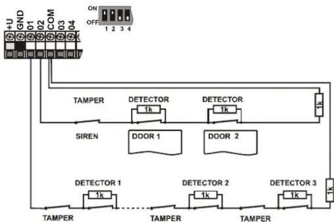
There are hard-wired input terminals for 01-10 device addresses on the main board. All hard-wired inputs act identically: double balanced loops which sense loop stand-by, activation or tampering as follows:
stand-by connected to COM via a 1 kΩ resistor (terminating resistor) activation connected to COM via a 2kΩ to 6kΩ resistor tampering connected to COM via a less than 700 Ω resistor (short-circuit) or connected to COM via a more than 6kΩ resistor (loop termination)

fig. 2 SA-200 magnetic detector connection

fig. 3 JS-20 Largo detector connection

fig. 4 One-loop connection of JS-25 Combo

fig. 5 Two-loop connection of JS-25 Combo (01 GBS, 02 PIR)
flowchart
graph TD
    A["+U GND 01 COM 03 04"] --> B["TAMPER"]
    B --> C["SIREN"]
    C --> D["DOOR 1"]
    C --> E["DOOR 2"]
    D --> F["TAMPER"]
    E --> G["TAMPER"]
    F --> H["1k DETECTOR 1k"]
    G --> I["1k DETECTOR 2k"]
    H --> J["TAMPER"]
    I --> K["TAMPER"]
    J --> L["TAMPER"]
    K --> M["TAMPER"]
    N["ON OFF 1 2 3 4"] --> O["1k DETECTOR 1k"]
    N --> P["1k DETECTOR 2k"]
    N --> Q["1k DETECTOR 3k"]
fig. 6 Connection of multiple detectors to the inputs – schematically
- The used input zone must be terminated by a 1kΩ resistor in stand-by state.
- When connecting a trigger contact to the zone, always use a parallel 1kΩ resistor. Thus it is possible to connect up to 5 trigger contacts in series.
- Tamper contacts should be connected in series (without resistors). They therefore interrupt the whole loop. You can use an unlimited amount of tamper contacts which can be combined with trigger contacts (with parallel resistors).
- The loop (input) reaction can be set. The NATURAL = delayed loop reaction is set in the factory.
- If you enrol a wireless device to the hard-wired input address, the corresponding terminal will be disabled (it will not affect the system).
- If you do not intend to use the hard-wire input or enrol a wireless device to its address, switch the corresponding switch to the OFF position (switch off the input).
3.3 Installation of additional hard-wire input modules
By adding the JA-82C module it is possible to extend the amount of inputs to twenty (addresses 01-20). When only one JA-82C module is installed (extension to twenty inputs) module position 4 must be used - see fig. 1.
When two JA-82C modules are installed, the maximum amount of thirty hard-wire inputs (addresses 01-30) is reached. All hard-wire inputs behave identically: they are double balanced inputs which are able to sense stand-by, activation and tampering and for which examples of connection and conditions stated in Chapter 3.2 apply in full scope.
When you install the module, relabel the terminal description with a sticker from the module package pursuant to the current position for which the module is intended (inputs 11-20 or 21-30). Insert plastic spacing posts on the openings in the module on the connector side and insert the prepared module to the selected position in the main board.
3.4 Radio module installation
The JA-82R radio module is installed in position 13 (see fig. 1). The module antenna is included in the package and it should be inserted in the groves on the side of the side of the box (see fig. 17). The antenna connectors are thus connected to the pins on the JA-82R module. The module installation enables the system to enrol wireless devices.
3.5 Y,X,V communicator module installation
Screw the selected communicator onto the holder bolted in the bottom right corner of the control panel box.
If you are installing a GSM communicator (Y) and there is a strong GSM signal in the place of installation, the self-adhesive antenna can be attached directly to the flat surface of the holder. If there is a weak GSM signal we recommend using some of the offered rod antennas.
If you use the combination of a GSM communicator (Y) and a telephone line communicator (X), install the phone line communicator above the GSM communicator using the supplied posts.
3.6 Control panel memory chip
The control panel memory chip plugs into its own socket. If you take the memory unit from the control panel and plug it into another control panel main board of the same type, the control panel settings (enrolled detectors, codes, set functions, etc.) are transferred.
Note:
• communicator settings are not stored in this memory
- do not plug or unplug the memory when the control panel is powered
- when you take the memory unit from a damaged control panel, its contents may be corrupted. It is therefore highly recommended to back-up the settings in a PC using OLink software
3.7 Wired keypad connection
The control panel can be operated and programmed by a JA-81E hard-wired keypad. A screened four-cord flat cable connecting the corresponding terminals should be used for permanent connection between the keypad and the control panel (see fig. 7.)
The keypad can also be connected to a bus connector on the control panel box using a flat cable (max 10 metres) with RJ connectors for the purpose of servicing or system debugging.

fig. 7 Wired keypad connection
Notes:
- When you use the INP keypad hard-wired input to connect the door detector, its reaction is always delayed (it triggers an entry delay) and it is located in section C.
- We recommend having only a single JA-81E hard-wired keypad in the system.
3.8 Control panel resetting
If you need to set the factory-default settings in the control panel, perform the following:
-
Disconnect the back-up battery and the mains (using the terminal board fuse),
-
Connect the RESET link and leave it connected,
-
Connect the back-up battery and the mains,
-
Wait until the green LED starts flashing and then disconnect the RESET link.
If you need to reset the control panel with preset parameters according to EN 50131-3 follow these next steps:
- Disconnect the back-up battery and the mains (using the terminal board fuse),
- Connect the RESET link and leave it connected,
- Connect the back-up battery and the mains,
- Wait until the green LED starts flashing and key in the sequence 8080 an finally disconnect the RESET link.
Notes:
- After a RESET, all wireless devices are erased from the control panel and all user codes and access cards are "forgotten".
- The Master code changes to 1234, and the service code to 8080.
- If resetting is disabled (see 6.8) it is impossible to reset the control panel.
4 Control panel power supply
Once the control panel is assembled and all modules are in place, you can proceed with putting the control panel into operation. We recommend switching the control panel on without any wired detectors connected, using only the wired keypad (if it is used in the system) for the first time. Only then should you continue connecting the detectors – beware of short circuits.
4.1 Backup battery connection
It is possible to use a 12V gel cell backup battery, with a capacity of up to 18Ah in the control panel. The EN 50131-1 standard requires a 12-hour minimum backup time in case of a power grid failure. For the standby consumption of all system devices, see fig. 8.

Always fix the backup battery in the box using the supplied (Velcro fastener) tape, thus avoiding possible injury caused by the battery falling out of the box.
ATTENTION – the backup battery is sold charged, avoid shorting out its terminals!
The average backup battery lifetime is up to 5 years after which it must be replaced. Checking its capacity during regular maintenance is recommended. The control panel automatically recharges the backup battery and monitors its condition. When the system runs only on the backup battery, the battery charge is monitored and a technical alarm is triggered before its complete depletion. The backup battery is then disconnected. Once the power supply has been restored, the battery reconnects and is recharged.
Ensure that the battery is correctly connected (Polarity: RED = positive +, BLACK = negative -).
When connecting a backup battery with screw leads, use two short wires with a fast-on connector as a size adapter.
| device | mA | note |
| JA-83K control panel | 30 | without a communicator |
| JA-82R module | 20 | |
| JA-82C module | 15 | |
| JA-81E keypad | 30 | |
| JA-81E RGB keypad | up to 100 | |
| JA-80H (N) keypad | 60 | including WJ-80 interface |
| JA-80Y communicator | 35 | |
| JA-80V communicator | 30 | |
| JA-80X communicator | 15 | |
| Wireless devices are not powered from the control panel | ||
fig. 8 power consumption of individual components
4.2 Power supply connection

Only a person with corresponding electro-technical qualification can connect the power supply.
The control panel power supply is double-insulated (safety class 2) and does not incorporate a protective grounding wire.
A two-cord double-insulated power cable with a minimum cross-sectional area of 0.75 to 1.5 mm2 should be used to supply power. The power cable should be connected to an independent circuit breaker (max 10 A), which should also function as a switch. To disconnect a two-pole power supply a power supply fuse must also be removed.
Connect the cable to the power terminals in the control panel. The power supply is equipped with T 1,6 A / 250 V fuse. Fix the cable firmly using the cable attaching bracket and two screws included in the package, but first make sure that the power cords are properly connected in the terminals.
4.3 Powering-up the control panel for the first time
- First check all the wiring, and if a GSM communicator is installed, insert its SIM card (PIN code disabled).
- Check the backup battery connection
- Switch the power supply on - a green LED starts flashing on the control panel board.
- If a hard-wired keypad is connected it indicates "Service" mode
- The control panel can also be set up via the supplied interface using OLink software - (A virtual keypad can be used in OLink to indicate system status).
- If you have neither the wired keypad, nor OLink, enrol a wireless keypad by the following means:
a) have an opened keypad and its battery ready,
b) check that the green LED in the control panel is flashing,
c) short the RESET link in the control panel for 1 second (enrollment mode opens),
d) install batteries into the keypad not far from the control panel
e) the keypad emits a beep and enrolls to the first free address. After that it displays "Enrollment" and offers another free address for enrollment
f) Pressing the # key exits enrollment mode and the "Service" *) message appears on the keypad
g) check whether the keyboard functions in the place where you intend to install it and then install its plastic rear part.
*) The keypad comes with English texts from production – these can be changed to other languages – see the manual.
Note: If the "Service" message fails to appear on the connected wired keypad or if the wireless keypad is not enrolled, the control panel settings are not the factory-defaults – perform a reset (see 3.8.)
5 OASiS wireless devices
The control panel had 50 addresses (01 to 50), allowing the enrollment of up to 50 wireless devices (detectors, keypad, key fobs, sirens etc.). A device can be assigned to an address either by enrollment or by typing its serial number while in Service mode (see 6.42).
Wireless devices can be installed at their intended locations and then enrolled to the control panel or vice versa. If there are any doubts as to the suitability of devices for communication, temporarily attach the devices (e.g. using adhesive tape) in the selected place and test radio communication before finalizing installation. Follow the manuals of the particular devices during their installation.
5.1 Enrolling wireless devices to the control panel
- The control panel must be in Service mode. If this is not the case, enter *0 service code (factory default: 8080). The control panel must be disarmed.
- Press the "1" key to enter enrollment mode. The first vacant address is then offered.
- You can select the desired address using the 1 and 7 keys (If the address is already occupied, the A indicator is lit).
- The device can be enrolled to the selected address by connecting its battery (power),
- Enrollment to the given address is confirmed by the A indicator and the next vacant address is then offered,
- Enrol all devices to the control panel one after another by connecting batteries to them. Press the # key to exit enrollment mode.
Notes:
- Enrolment of a wireless device to an address disables the corresponding hard-wired input terminal (when the device is erased, the terminal is enabled again).
- RC-8x type key fobs are enrolled to the control panel by pressing and holding two buttons at the same time: 📄+ 🔍 or ●+ ○. This means that a 4-button key fob can be enrolled to the control panel as two different pairs of buttons and different features can be assigned to them – see 6.40.
- Only a single device can be enrolled to each address,
- When an address is occupied (the A indicator lights), no more new devices can be enrolled to it,
- If a device has already been enrolled to an address, and it is then re-enrolled to another address, the device's address assignment changes from the original address to the new one,
- If a device cannot be enrolled to the control panel, it does not have a good connection to the control panel (the device must be at least 2 m away from the control panel and an antenna must be connected to the control panel during enrollment),
- To re-enroll a device, first disconnect its battery. Then wait about 10 seconds (or, to save time, press and release the tamper switch on the device), before you switch it on again
- A sub-control panel can be enrolled to a master control panel by keying in the sequence "299" on the keypad of the sub control panel which must be in Service mode,
- If you intend to use the final door function, the final door detectors must be enrolled to addresses from 01 to 05 or from 46 to 50 (see 6.22)
5.2 Testing enrolled wireless devices
- The control panel must have its antenna connected and it must be in Service mode (If this is not the case, enter *0 service code (factory default: 8080). The control panel must be disarmed),
- Trigger the device to be tested (if it is a detector, close its cover first and then wait until it is ready for testing),
- The keypad (its cover should be flipped open) beeps and displays a description of the signal received from the device under test
- You can test the enrolled devices one after another by activating them one by one. You can carry the wireless keyboard with you during the inspection.
Notes:
- JA-80P and JA-85P motion detectors can be tested max. 15 minutes after closing their cover. After that the detectors ignore frequent movements (see the detector manual).
• Devices can also be tested in Service mode – see 7.4.
5.3 Signal strength measuring
- The control panel must have its antenna connected and it must be in Service mode (If this is not the case, enter *0 service code (factory default: 8080). The control panel must be disarmed),
- Key in 298, and the lowest enrolled device address is displayed
- Trigger this device. The keypad (its cover should be flipped open) displays signal quality ranging from 1/4 to 4/4,
- Use the 1 and 7 keys to select other enrolled devices and measure their signal strengths,
- Exit signal measuring by pressing the # key
Notes:
- The JA-80P and JA-85P motion detectors can be tested max. 15 minutes after closing their cover. After that the detector ignore frequent movements (see the detector manual),
- Measuring the signals from the JA-80L internal siren can be activated by pressing its button. The JA-80A outdoor siren and wireless keypad signal can be measured by triggering the IN input or triggering its cover tamper switch,
- Each installed device should have the minimum signal strength of 2/4. If the signal is too weak, the device should be relocated or higher control panel sensitivity can be selected. (see 6.36) Alternatively, the control panel can be equipped with an external antenna.
- This measurement shows the strength of the signal received from the device by the control panel.
- The wireless keypad can be carried during device testing, its tamper contact can be disabled via the jumper (near the tamper contact – do not forget to re-enable the tamper upon finishing the servicing) – Note: the keypad usually has a slightly shorter communication range than the detectors. Therefore, if carried to more-distant detectors the triggering of the detectors might not be shown.
- The most convenient way of measuring is via a computer using OLink SW.
5.4 Erasing enrolled devices
- The control panel must be in Service mode. If this is not the case, enter *0 service code (factory default: 8080). The control panel must be disarmed,
- Key in "1" to enter enrollment mode and select the desired address of the device you wish to erase using the keys ^▲ 1 and ▼7 ,
- Press and hold the "2" key until a beep is heard and the A indicator turns off,
- When all the desired devices have been erased press #.
Notes:
- To erase all wireless devices, press and hold the "4" key in enrollment mode,
- If a wireless keypad is erased by the above mentioned means, it stops communicating with the control panel and you must re-enrol it again (see 3.4).
5.5 Enrolling the control panel to UC and AC modules
If you wish to transmit PGX and PGY programmable output signals to the UC-82 and AC-82 output modules, you must enroll the control panel to these modules as follows:
- The control panel must be in Service mode. If this is not the case, enter *0 service code (factory default: 8080). The control panel must be disarmed,
- Enter the control panel enrollment mode on the UC or AC module (see the manual of the particular module),
- Key in 299 on the control panel keypad – the LEDs on the module will flash a few times.
Notes:
- we recommend locating the module close to the control panel during enrollment or carry the wireless keypad close to the module,
- the control panel can be enrolled to the desired number of UC/AC modules (each PG output can thus have an output at an arbitrary number of places in the house),
- PG outputs are enrolled to UC and AC module relays individually (PGX output to the X relay, PGY output to the Y relay). This means that either one or both modules can be enrolled to the module if requested,
- Only one control panel can be enrolled to a UC or AC receiver (a control panel repeats its PG signal every 9 minutes).
6 Control panel programming
The most convenient way to program the system is to use a PC running OLink software. However, the system can also be programmed by keying in the below mentioned sequences. The sequence summary table can be found at the end of this manual.
- The control panel must have its antenna connected and it must be in Service mode (If this is not the case, enter *0 service code (factory default: 8080). The control panel must be disarmed).
- Enter the appropriate programming sequences – see the following description (an unfinished sequence can be escaped from by pressing the # key).
• To exit Service Mode press the # key.
6.1 Exit delay time
An exit delay time occurs while setting (arming) the system. During this time period delayed or next-delayed detectors can be triggered without an alarm occurring. To program the delay time, enter:
20x
where x is a number from 1 to 9 determining the duration in steps of tens of seconds (1=10 s, 2=20 s,...)
If there is a final-door detector in the system then the exit delay is multiplied by 30 s instead (1=30 s, 2=60 s,...).
Example: To program a 20 seconds exit delay, use the sequence 202 (if there is a final-door detector, a 60 seconds delay will result).
Factory default setting: x = 3
6.2 Entrance delay time
The entrance delay time is provided to unset (disarm) the system after a first delayed detector has been triggered. To program this time, enter:
21x
where x is a number from 1 to 9 determining the delay in multiples of 5 seconds (1=5 s, 2=10 s,...)
If the entrance delay is triggered by a final-door detector, then parameter x is multiplied by 30 s instead. (1=30 s, 2=60 s,...) – in this case it means that the entrance delay would be six times longer than if it had been triggered by an ordinary detector.
Example: To program a 20 seconds entrance delay, enter the sequence 214 (if the delay has been activated by a final-door detector, a 120 seconds delay will result instead).
Factory default setting: x = 4
6.3 Alarm duration time
This parameter limits the duration of a triggered alarm. After the alarm state expires, the control panel will return to its previous state, i.e. as before the alarm occurred. The alarm state can also be terminated by an authorised user. To program the alarm duration enter:
22x
where x is a number from 0 to 9 determining the alarm duration: 0 = 10 s, 1 = 1 min., 2 = 2 min. up to 8 = 8 min., 9 = 15 min.
Note: There can be up to 5 different alarms in the system: intruder, tamper, fire, panic, and technical alarm.
Example: Alarm duration of 5 min. = sequence 225
Factory default setting: 4 minutes
6.4 PGX and PGY functions
The functions of PGX and PGY can be programmed by entering sequences:
23x for PGX
24x for PGY
where x determines the PG function or the event which triggers a change of PG state:
| x | Unsplit system Split system | |
| 0 | Completely (ABC) set = PG on Alarm A = PG on | |
| 1 | Anything set = PG on | Alarm B = PG on |
| 2 | AB set (not ABC) = PG on | Entrance delay A = PG on |
| 3 | Fire alarm = PG on | Entrance delay B = PG on |
| 4 | Panic = PG on | A set = PGX on, B set = PGY on |
| 5 | Any alarm = PG on(excluding Panic) | Panic A = PGX onPanic B = PGY on |
| 6 | AC dropout = PG on | Fire = PGX on, dropout = PGY on |
| 7* | ON/OFF | |
| 8* | 2 seconds pulse | |
fig. 9 PG outputs settings
* The ON / OFF and 2 second pulse functions can be controlled from
the keypad by keying in *8, *9 or using the *ON and #OFF keys (see 6.26) or they can be operated by a code or card. These PG output functions can also be controlled by signals from keyfobs or detectors (see 6.40).
Notes:
- The PGX and PGY outputs are not only provided as control panel terminals, but the signals are also wirelessly transmitted for UC and AC modules.
- The status of PGX and PGY outputs can be displayed by pressing the “?” key. The names of the outputs can be edited – see 6.47.
Example (for unsplit systems): Assigning an ON/OFF function to the PGX output = sequence 237. Assigning a panic function to the PGY output = sequence 244.
Factory default setting: PgX= ON/OFF, PgY= anything set
6.5 Changing telephone numbers in maintenance mode
If the control panel is equipped with a JA-8xY, JA-80V or JA-80X communicator, then this sequence enables the holder of the master code (system administrator) to program telephone numbers for alarm reporting in maintenance mode. Programming telephone numbers is the same as in Service mode (see communicator manual):
251 programming enabled
250 programming disabled
Factory default setting: programming disabled.
6.6 Radio interference indication
The control panel is capable of detecting and indicating radio communication jamming. If this function is enabled, any radio jamming longer than 30 s will trigger fault indication and if armed the alarm is triggered.
261 enabled
260 disabled
Factory default setting: disabled.
Note: In some places the system can be permanently or occasionally affected by radio interference, e.g. by nearby radar stations, TV transmitters etc. In most cases the system can tolerate such effects, but with this anti-jamming function disabled.
6.7 Radio communications supervision
If enabled, the control panel can routinely check wireless connections to its devices. If communication with a particular device is lost, the control panel can communicate a fault indication to the user:
271 indication enabled
270 indication disabled
Notes:
• In the OASiS system, communication is checked every 9 mins.
- In detectors used for car protection, (JA-85P, JA-85B) it is possible to disable radio communication supervision. It allows car detectors to be excluded from supervision to avoid alarm triggering when driving the car away from the system.
- Random dropouts in communication can occur in some installations near e.g. airports or TV towers. The system is still reliable in such situations as high-priority transmissions are repeated often. We recommend disabling communications supervision in cases like this.
Factory default setting: supervision disabled.
6.8 RESET enabled
If resetting is enabled, it is possible to return the control panel to its original factory-default settings via the reset link on the main board. (see section 3.8).
281 RESET enabled
280 RESET disabled
Warning: If resetting is disabled and the service code has been forgotten, it would no longer be possible to enter Service mode. If this happens, send the control panel back to the manufacturer.
Factory default setting: RESET enabled.
6.9 Enrollment to a sub control panel for setting control
If the control panel has another OASiS control panel enrolled as a sub-system, then the sub-system reports all alarms, tampering and faults to the master control panel. The master control panel reacts to particular signals accordingly, and displays the sub control panel's address as the source.
After sub control panel enrollment to the master control panel, these two panels are independent concerning setting control. Each panel can be operated by its own keypads or key fobs. If there is an alarm or fault in the sub control panel, it is also indicated on the master control panel. In this configuration it is impossible to control the sub control panel from the master control panel.
If it is desired to control a sub control panel from a master control panel (i.e. setting/unsetting), it is possible to enroll a JA-8x OASiS master control panel to a sub control panel as a remote control as follows:
- First enroll the sub control panel to the desired address in the master control panel by entering 299 on the sub control panel's keypad in Service Mode – see 5.1 for full details.
- Switch the master control panel to Service Mode.
- In the sub control panel, enter enrollment mode by keying in "1" in Service Mode and select the desired address.
- In the master control panel enter 290. This way the control panel will enroll to the sub control panel to the desired address as a remote control.
- Switch both control panels to maintenance mode and check that all-section setting of the master control panel also sets the sub control panel and unsetting the master control panel unsets the sub control panel too. Expect approximately 2 seconds of delay between control panels.
Notes for operating the sub control panel:
- The sub control panel can still be operated independently via its keyfob or keypad e.g. it can be set while the master control panel is unset. If the master control panel changes its status later on, it will then control the sub control panel to achieve synchronisation.
- To disable the master control panel's ability to control the sub control panel, enter the sub control panel's enrollment mode, select the address where the master control panel is enrolled and erase the master control panel from this address by pressing and holding key 2.
6.10 Master code reset
If the master code has been forgotten or a card lost, it is possible to use the following sequence to reset the master code to the factory-default 1234:
291
Note: Resetting the master code has no effect on other codes and cards. Resets are recorded in the control panel memory and sent to the ARC (Alarm Receiving Centre, previously called a central monitoring station).
6.11 Enrollment to other devices (UC, AC)
Keying in 299 sends an enrollment signal to enroll the control panel to UC-82 or AC-82 receiving modules (see 5.5). This sequence can also be used to enroll a sub control panel to a master control panel (see 6.9).
6.12 Setting (Arming) without an access code
"Hot" setting keys (short-cut keys for setting) A, B, ABC or entering "*number" can be enabled for use without a valid access code or card. If disabled, then hot key use or entering "*number" has to be followed by a valid access code or card to have any effect:
| Function/sequence 301 300 | ||
| All-section setting | ABC key Code/card | |
| Setting of A | A key A key, code/card | |
| Setting of AB (or B) | B key B key, code/card | |
| Event memory recall | *4 | *4 code/card |
fig. 10 setting / arming with or without code
- If you remotely operate the system by mobile phone, you can press *1 for the ABC key, *2 for key A, and *3 for key B.
- Controlling the PG outputs by keying in *8 or *9 or pressing *ON and #OFF is unaffected by these settings. These keys can however be disabled by a special sequence (see 6.26).
Factory default setting: Setting (arming) without an access code enabled.
6.13 Triggered-detector indication
Pressing the ? key checks if any detectors are permanently triggered, e.g. if any doors or windows are open. The following sequence enables the display of text concerning active detectors.
311 indication enabled
310 indication disabled
Factory default setting: indication enabled
6.14 Confirmation of intruder alarms
To reduce the risk of false alarms and to comply with British standard BSI DD243, the control panel allows alarm confirmation logic to be enabled as follows:
321 confirmation logic enabled
320 confirmation logic disabled
Confirmation logic:
- If the system is set (armed) and any intruder detector gets triggered, i.e. a detector with an instant, delayed, or next-delayed reaction, an
alarm will not be caused but the control panel will record a so-called unconfirmed alarm.
- If any other intruder detector is triggered in a set section within 40 minutes of the above event, an intruder alarm will be triggered. If no other detector is triggered during this period, the control panel will stop waiting for confirmation.
- The alarm must be confirmed by another detector than the first one, and if the second one is a motion detector its detection area must not cover the same area as the first detector to be triggered. This must be ensured by the proper location of detectors.
- An unconfirmed alarm is recorded in control panel memory but can also be sent to the ARC, or to the user by SMS report.
- If the first triggered detector has a delayed reaction, it will start a so-called unconfirmed entrance delay. This delay is indicated the same way as an ordinary entrance delay, but if no other delayed detector is triggered during this delay, there will be no alarm if the unconfirmed entrance delay is exceeded, with another unconfirmed alarm being recorded in the control panel memory. If there is any other delayed or next-delayed detector triggered during the entrance delay period, it will confirm the entrance delay, and if this delay is exceeded (due to no unsetting being done) it will trigger an intruder alarm at the end of the delay.
- If a delayed detector is triggered within 40 minutes after the triggering of an unconfirmed alarm or the moment the unconfirmed entrance delay is exceeded, the confirmed entrance delay starts running and when it times out (due to no unsetting being done), an intruder alarm is triggered.
- If the unconfirmed entrance delay is confirmed by an instant detector it will trigger an internal warning (IW) alarm immediately (e.g. an internal siren) and if the entrance delay times out then an external alarm (EW) will be triggered.
- An unconfirmed alarm can be confirmed by any other intruder detectors in the system as long as the detectors are assigned to a set (armed) section.
- The confirmation of intruder alarms concerns only detectors with instant, delayed, or next-delayed reactions. It has no effect on fire, panic, 24-hour, tamper, or technical alarms. These alarms are triggered immediately without confirmation.
Note: When the first detector is triggered it begins a process which waits 40 minutes for any possible confirmation of the alarm (unconfirmed alarm status) during which the system works exactly the same way as if the confirmation function had not been enabled.
Warning: If intruder alarm confirmation is enabled, it is necessary to install enough detectors in the building to detect an intruder even if he/she is only moving in one particular place.
Factory default setting: confirmation disabled
6.15 Exit delay beeps
The exit delay can be indicated by beeps from the keypad and internal wireless siren. The beeps get faster in the last 5 seconds.
3 3 1 Beeps enabled
3 3 0 Beeps disabled
Factory default setting: Beeps enabled.
6.16 Exit delay beeps while partially setting (arming)
The exit delay caused by partial setting, e.g. using the A or B key, can also be indicated by keypad beeps and internal-siren beeps. The beeps get faster in the last 5 seconds. The feature is linked to 331 parameter setting.
341 Beeps enabled
340 Beeps disabled
Factory default setting: Beeps disabled.
6.17 Entrance delay beeps
The entrance delay can be indicated by keypad beeps and internal-siren beeps:
351 Beeps enabled
350 Beeps disabled
Factory default setting: Beeps enabled.
6.18 Setting (arming) confirmed by wired-siren chirp
A hard-wired siren connected to the IW terminal of the control panel can audibly indicate setting by one beep, unsetting by two beeps and unsetting after an alarm by three beeps. Four beeps mean an invalid attempt at setting the system has occurred.
361 Chirps enabled
360 Chirps disabled
Note: In JA-80L wireless sirens, this function can be individually enabled for each siren. (see the siren manual).
Factory default setting: Hard-wired siren chirps disabled
6.19 Sirens always sound during audible alarms
Using this sequence it is possible to disable internal and external sirens (IW and EW) if any part of the system is unset (partial setting), i.e. when someone is home.
371 Sirens always sound during audible alarms
370 Sirens only sound during audible alarms when all sections are set, i.e. no one is at home
Factory default setting: Sirens always sound during audible alarms.
6.20 Wireless siren alarm enabled (IW and EW)
This setting is for enabling and disabling wireless sirens in the system:
381 wireless sirens enabled
380 wireless sirens disabled
Note: This setting applies both to internal and external wireless sirens.
Factory default setting: wireless sirens enabled
6.21 Bypass user approval
This setting can change the function of the system when it is set (armed) and if there is:
• any detector triggered
- any tamper alarm
- any trouble in the power source
- lost communication with any wireless device (for more than 20 minutes)
- any panic button triggered
If bypass user approval is set (391), then during setting (arming), the system notes which problems mentioned above are active and displays informative text on the keypad and only bypasses them if the user approves the bypassing by keying in a * within 6 seconds of being notified.
The system has a built-in auto-bypass function (setting 390) so that if any number of detectors are being triggered during setting (arming) then they will be bypassed and ignored automatically without consulting the user.
391 Approval by pressing the * key is requested from the user
390 Bypassing occurs automatically without user approval
Notes regarding setting the system with (a) triggered detector(s) or problems as mentioned above:
- Details can be viewed by pressing the ? key (e.g. open doors or windows).
- If a wireless keyfob is used to set the system and auto-bypass user approval is enabled, the system will set without bypass approval, i.e. setting by keyfob does not trigger an approval request.
- The automatic bypass of a detector will end after the detector has been de-triggered (for example if a door is closed) or the problem disappears.
- If auto-bypass user approval is enabled and Service mode is being exited while a detector is being triggered, the installer will be notified about the bypass. The installer can then approve the bypass by pressing # twice.
• To comply with the EN-50131-1standard 391 should be set.
Factory default setting: Bypassing occurs automatically without user approval.
6.22 Final-door detectors
In this mode, up to 5 detectors can be defined as final-door detectors and assigned to addresses 01 to 05 or 46 to 50 in order to make leaving a building much easier, especially via a garage:
65x
where x 0 = none, 1 = detectors on addresses 01 to 05, 2 = detectors on addresses 46 to 50.
Description of final-door detector mode:
- If a final-door detector is used in the system then the value of x for exit delay programming is multiplied by 30 s (see 12) thereby extending the delay, and if an entrance delay is triggered by a final-door detector then the value of x for the entrance delay is also multiplied by a larger value of 30 s.
- A final-door detector should be programmed to have a natural reaction, otherwise it works as it is set (e.g. instant reaction).
- Only door/window detectors, hard-wired control panel inputs or hard-wired inputs in the wireless keypad unit to whose alarm input the final-
door detector is connected should be assigned to the addresses which you set with this sequence as belonging to final-door detectors.
- If a final-door detector is used for a garage door, no instant detectors should be inside the garage. Next-delay detectors would however be acceptable.
Setting (arming) the system with a final-door detector:
- After entering a request to set the system, an exit delay of between 30 to 270 seconds will begin and be indicated.
- If a final-door detector is triggered during the exit delay, the exit delay will be extended by the time in which the detector is still triggered. So, if for example, the door is left continuously open, the exit delay will never end.
- If a final-door detector is de-triggered, the system will wait five more seconds during which beeping gets faster, and if the door is not opened again during this short period, the exit delay will terminate and the system will be set immediately.
- The duration of the exit delay therefore depends on the time the final door stays open. For instance, in winter if the driveway in front of a garage needs to be cleared of snow there will be plenty of time to do it, and in summer when garages can be exited easily and therefore quickly, the exit delay can be rather shorter. The exit delay only depends on the length of time the garage door is left open.
- If no final-door detectors are triggered during the exit delay, the system will provide an exit delay and then set.
- If the final door detector stays continuously triggered, an endless exit delay will result with the system never being set. This means all delayed and next-delayed detectors will not be set (armed).
- If there are multiple final-door detectors in the system, the exit delay is extended if any of them is triggered and ends after all final-door detectors have been de-triggered.
Unsetting (disarming) the system with a final door detector:
- If a final-door detector gets triggered in a set (armed) system, an entrance delay will begin with a duration of between 30 and 270 seconds.
- If a normal delayed detector gets triggered while the user enters a building, the system starts an ordinary entrance delay of between 5 and 45 seconds.
- If a final-door detector is triggered first, a longer entrance delay will begin. If during this delay an ordinary delayed detector is then triggered, the remaining entrance delay will then be shortened to the delay associated with detectors of this kind.
Note: Only use status-reporting detectors such as the JA-81M or JA-82M, or the hard-wired inputs of wireless keypads, or the hard-wired inputs of a control panel as final-door detectors. This mode is unsuitable for pulse detectors such as JA-80P motion detectors, or the hard-wired inputs of JA-81E hard-wired keypads which also have a pulse reaction.
Factory default setting: No final-door detectors in the system.
6.23 Partial setting (arming) or system splitting
The control panel can be configured in three ways as follows:
- the entire system sets and unsets together or,
- the system partially sets and unsets to protect only certain parts of a house during the day, while people are still present in the unset parts or,
- the system can be split into two independently set/unset sections for two separate users and also with a common section if desired.
Program as follows to configure the system as desired:
66x
where x
0 = unsplit system (setting/unsetting as an entire system)
1 = partial setting (for setting sections A, AB, or ABC)
2 = split system (sections A and B can be set/unset independently by separate users, with section C only being automatically set when both A and B are manually set)
Notes:
- For an unsplit system, all intruder detectors are set/unset immediately after the user sets/unsets the system. Assigning wireless devices, access codes and keyfobs to various sections of the system has no effect in this mode.
- Partial setting is especially suitable for homes and apartments where the user wishes to protect different parts of the premises during the day. Detectors can be assigned to three sections, A, B and C. Using setting (arming) key A on the system keypad, you can set section A, e.g. setting the garage area in the afternoon. Using setting key B you can set sections A and B simultaneously e.g. in the evening before going to sleep to protect the garage (section A) and the ground floor of the house (section B). The ABC total-setting button is used when leaving the home to set all sections, A,B and C. If you then use a valid access code or card for unsetting (disarming), all sections will be unset. The assignment of codes or cards to sections has no effect in this mode. A and B keypad buttons are used for partial setting.
- A keyfob can also be used for partial setting control. Buttons 🔒 and 🔒 can be programmed to set and unset the entire system, and buttons 🔒 can be programmed for setting (arming) sections A and AB respectively to partially set the system (this pair of buttons must be assigned to section A or B if it is to be used for partial setting. See 6.40 for details on partial setting by keyfob).
- Split system mode is especially suitable where two families (A and B) live in a single house or two companies (A and B) share one building. The system behaves as two independent systems, one being section A and the other, section B. There is also a common section C which is only set if section A and section B are set at the same time and is commonly used for shared entrances, doors etc. Codes and keyfobs can be assigned to 3 sections. Codes and keyfobs assigned to section A allow access to section A only, whereas codes and keyfobs assigned to section B allow access to section B only. Codes and keyfobs assigned to section C allow the user to access the whole house, as they control all sections (similarly to the Master code).
- Partial setting only has an effect on intruder detectors, i.e. detectors with instant, delayed or next-delayed reactions. Detectors with fire, tamper, panic and 24-hour reactions are always able to trigger their kind of alarm immediately, whether their section is set (armed) or not.
Factory default setting: Unsplit system.
6.24 Automatic summer time (daylight saving time)
If enabled, this feature automatically offsets the system time to that of summer time, or daylight saving time as it is also known:
6801 automatic summer time enabled
6800 automatic summer time disabled
Note: If automatic summer time is enabled, the control panel's internal clock is automatically offset by +1 hour on March 31 ^st at midnight. The offset is then removed on October 31 ^st at midnight to return to winter time.
Factory default setting: automatic summer time disabled
6.25 Pulse reaction of tamper sensors
This feature allows permanently triggered tamper sensors to be ignored:
6811 ignore permanently triggered tamper sensors, i.e. only react to an increase in the number of triggered tamper sensors.
6810 react with a tamper alarm to all triggered tamper sensors
Note: Ignoring permanently triggered tamper sensors is useful for example when carrying a detached wireless keypad around with you during installation as this avoids unnecessary tamper indication. If you choose to ignore permanently triggered tamper sensors, their de-triggering is not reported to the ARC.
Factory default setting: react with a tamper alarm to all triggered tamper sensors
6.26 Operating the PG outputs using \* 8 and \* 9
Using this feature the PGX and PGY outputs can be controlled from the keypad by pressing the *8 and *9 keys (or keys ON and OFF).
6821 control enabled
6820 control disabled
Notes:
- The PG outputs can only be operated from the keypad if they have their ON/OFF or pulse functions enabled.
- In addition to controlling the PG outputs using keys *8 and *9, PG outputs can also be controlled by access codes, access cards, keyfobs and detector signals (see 6.40 and 6.41 for details).
- If a PG output should only be operated by a valid access code or card, then control by *8 and *9 should be disabled and the codes and cards should be programmed to control the PG outputs instead (see 6.41).
Factory default setting: control enabled
6.27 Permanent alarm status display for a set system
The below sequence enables the permanent display of alarm status on the keypad unit, even if the system is set.
6831 permanent status display enabled
6830 display time a maximum of 3 minutes if any section is set (armed)
Notes:
- European legislation requires status displaying to be suppressed within three minutes of setting (arming) the system, no matter how much or
little of the system is set. This feature can be used to ignore this requirement if appropriate.
- The wireless keypad can continuously display the status if powered by an external power supply. If powered by internal batteries the keypad will turn off its display after 20 seconds of not being used (in Service Mode the display turns off after 15 minutes of no use by the installer).
Factory default setting: only 3 minutes of display time
6.28 Tamper alarm if unset
According to EU legislation an unset (disarmed) system should not audibly sound a tamper alarm if tampering occurs. If the audible indication of tamper alarms is required while the system is unset (disarmed) then this can be enabled by the following sequence:
6841 audible tamper alarm even for an unset system
6840 silent tamper alarm for an unset system
Notes:
- Even if tamper alarms are silent, they are still recorded in the control panel memory and reported to the end user by SMS, and also to the ARC if used.
- If the sequence 370 has been programmed, then tamper alarms will be silent if the system is unset or partially set.
Factory default setting: silent tamper alarms for an unset system
6.29 Recording PG output activation to memory
The activation of PGX and PGY outputs can be recorded in the control panel's memory (for example if the outputs are used for access control). This can be enabled by the following sequence:
6851 enabled
6850 disabled
Factory default setting: recording enabled
6.30 Engineer reset
This is a special function requested by the DD243:2004 standard. It can only be used when the alarm system is connected to an alarm-receiving centre. When a confirmed alarm is activated the control panel is completely blocked – it cannot be operated by any user, master or service code until an engineering reset is performed by an ARC code. This function is required in some countries only and you can enable it by the following sequence:
6861 Engineer reset enabled
6860 Engineer reset disabled
Factory default setting: Engineer reset disabled
Notes:
- To enable the confirmation of intruder alarms (requires two detectors to be triggered in different zones within a definite period) – use sequence 321
- Reporting to ARCs must be locked by a digital code.
- The keypad shows the text "Eng. reset req'd" and the system stays blocked until the ARC code is used via the communicator (see the communicator manual).
- The feature is supported when a JA-80Y version XA61008 or higher, or a JA-80V version XA64005 or higher is installed.
6.31 Social alarm feature
If this function is enabled the signals from delayed, next delayed and instant detectors are regularly checked in disarmed mode. If there is no active signal (no movement inside) for more than 16 hours a panic alarm is triggered.
6871 social alarm enabled
6870 social alarm disabled (default)
Note: This feature can be used to alert the user that the system is unintentionally disarmed.
6.32 Annual check notification
This sequence enables the user and installer to be notified of the necessary time for an annual technical check:
6900 notification disabled
6901 notification enabled
Notes:
- An annual technical inspection notification is displayed as text on the keypad display and can also be sent as an SMS to the end user and/or installer and/or as a report code to an ARC, if used.
- Annual technical inspection notification text disappears on entering Service Mode.
- When this notification is enabled, exiting Service Mode will cause a notification to occur in the next year on the first day of the month in which it was set. (e.g. if you set the annual check notification on the
15th October 2007, the notification is displayed on the 1st October 2008.)
- When this notification is enabled, exiting Service Mode will cause a notification to occur every twelve months later (the same day and month).
- If you wish to receive a notification earlier than a year later, change the internal clock settings to the day and month you prefer before exiting Service Mode by entering 4hhmmDDMMYY, and then re-adjust the clock to the correct time in maintenance mode. By tricking the system this way, you can be notified on the desired date. (see 6.45, entering and exiting maintenance mode does not change the notification date).
Example: If the date is 10 January 2007 and you wish to receive a notification 6 months later on 10 July 2007, while still in Service Mode change the system clock to 10 July 2007, i.e. the day and month of the desired notification date. Then exit Service Mode and re-adjust the clock to the correct time in maintenance mode.
Factory default setting: Annual inspection notification disabled.
6.33 Only single alarm indication
If this function is enabled, then only one intruder alarm may be indicated at a time. Once an intruder alarm has been triggered and has still not ended, then no more alarms can be indicated no matter how many more times triggering occurs. After the alarm has ended, the system is then ready to indicate the next single intruder alarm.
This is to limit the number of SMS reports sent if hard-wired PIR detectors capable of being frequently triggered are installed in the system and the system is not unset (disarmed) properly when someone enters the building.
6910 multiple simultaneous intruder alarms allowed
6 9 1 1 single intruder alarm allowed only
Note:
- A panic alarm can always be triggered with no limits (except when in service and maintenance modes),
- Apart from this limitation in the number of simultaneous intruder alarms, the system also checks to see if any detector is triggering multiple alarms during the period in which the alarm is set. Any such undesirable detector is then automatically bypassed every time the system is set, if it has caused at least four alarms in a row. This bypass lasts until another event in the system caused either by a different detector or the user.
6.34 Setting (arming) by service code
Normally, it is not allowed to control the system via the service code. Using this sequence, the installer can be authorized to set and unset the system by means of a valid service code. This feature should only be enabled with the explicit approval of the master code holder (system administrator):
6920 disabled
6921 enabled
Factory default setting: disabled
6.35 Audible panic alarm
If enabled, panic alarms can be indicated by internal and external warning devices (sirens on IW and EW):
6930 silent panic alarm
6931 audible panic alarm
Note: If the sequence 370 is used, panic alarms are silent if any section of the system is unset.
Factory default setting: silent panic alarm
6.36 Higher control-panel receiver-sensitivity
If enabled, this feature can extend the communication range between the control panel and its wireless devices if there is no radio frequency interference in the premises.
6940 standard control panel sensitivity
6 9 4 1 higher control panel sensitivity
Note: The sensitivity of the control panel receiver should only be increased if there is no RF interference as the radio range would only be reduced if interference was present.
Factory default setting: standard control panel sensitivity
6.37 Access by code plus card
This feature increases security against unauthorised setting/unsetting (arming/disarming):
6950 system access by code or card
6951 system only accessed by code and card if both are assigned to the same user position
JA-83K control panel installation manual - 11 - MKG51101
Notes:
- The system has up to 50 user positions (01 to 50) each capable of having an access code and an access card assigned to it. If both a code and a card are assigned to a user then the above sequences (6950 and 6951) determine whether the user can use a code or a card or whether he must present both a card and a code to gain control over the system. If both, a card and a code have to be presented, the order in which they are done is unimportant.
- If only a card or only a code is assigned to a user, then the above settings have no effect on users like this.
Factory default setting: system operated by code or card
6.38 Audible 24 hour intruder alarm
The 24-hour intruder alarm which can be triggered whether the system is set or not, and can also be silent or audible (IW and EW) according to the following sequences:
6960 silent 24-hour intruder alarm
6961 audible 24-hour intruder alarm
Note: If sequence 370 is programmed, the intruder alarm will be silent if any section in the system is unset.
Factory default setting: audible 24 hour intruder alarm
6.39 Service mode only with service and user code
To prevent the installer from accessing Service Mode without a user's permission, this feature (if enabled) makes it compulsory for the any user code (or master code) to be entered directly after entering the service code to access Service mode. Service Mode can then be entered by keying in .0 service-code user-code (or master-code).
6970 Only service code needed.
6 9 7 1 Service code and user-code (or master-code) needed.
Factory default setting: Only service code needed.
6.40 Device reactions and section assignment
The following sequence programs the characteristics of system devices:
61 nn rs
where nn is the device address from 01 to 50 (01 to 10 ... 30 can either be the hard-wired input terminals in the control panel or enrolled wireless devices) r is the reaction index from 0 to 9 – see fig. s is the section 1 = A, 2 = B, 3 = C (only has an effect if partial setting or system splitting is used – except for PG output control – See 6.23)
| R | Reaction | Notes |
| 0 | Disabled (none) | For temporarily disabling codes or devices including tamper sensors |
| 1 | Natural | For detectors = instant, delayed or fire (selectable in detectors by DIP switch)For hard-wired inputs of the control panel or keypad = delayedKeyfobs (or ●) = set, (or ○) = unset, both buttons = panicCode = set/unset (see reaction r=9) |
| 2 | Panic | Triggers a panic alarm (audible or silent, see 6.35) |
| 3 | Fire | Triggers a fire alarm |
| 4 | 24 hours | Triggers an intruder alarm even if the system is unset (audible or silent – see 6.38) |
| 5 | Next delay | Always provides an exit delay. An entrance delay is only provided if it is triggered shortly after a delayed detector. |
| 6 | Instant | If activated in a set (armed) section, it triggers an intruder alarm instantly |
| 7 | Set | Sets its own section of the system |
fig. 11 Device reactions
fig. 11 continues
| R | Reaction Notes | |
| 8 | PG output control | The value of the s parameter determines which PG output is controlled: s= 1= PGX, s=2=PGY or s=3=PGX & PGY. To use this function the PG output involved has to be programmed to the ON/OFF or pulse functions.If the reaction is triggered by:a code (card) – the PG output changes its state (ON,OFF,ON,OFF......) or a pulsed switching event is generated after a valid code or card is used. If a code or card is programmed this way, it cannot be used for setting (arming) control. One or more (up to 50) different codes can be programmed to operate PG outputs, if desired.a keyfob – one button in a pair is used to switch a PG output ON, the second one to switch it off or each of them generates a pulsed switching event. If a keyfob is programmed this way, it cannot be used for setting (arming) control. Each PG output can have as many associated keyfobs as desired.a detector – the PG output copies the status of the detector or it generates a pulsed switching event when the detector is triggered. Only one detector should be programmed to a PG output ON/OFF reaction and should not be combined with keyfob or keypad control as the detector repeats its status every 9 minutes and it would override the signal from the keypad or keyfob. |
| 9 | Set/unset | Toggles the system statusSET,UNSET,SET,UNSET etc |
fig. 11 Device reactions
Guidance on assignment to sections:
| Assigning keyfobs with natural reactions to sections | ||||
| s | button | Unsplit system | Partial setting | $plit system |
| 1 | set set A | set A | ||
| unset set | AB unset A | |||
| 2 | set set A | set B | ||
| unset set | AB unset B | |||
| 3 | set set ABC | set ABC | ||
| unset unset ABC | unset ABC | |||
fig. 12 Buttons to section
- If partial setting is programmed then detectors can be assigned to sections: A (s=1), B (s=2) a C (s=3). The three possible setting (arming) options are as follows:
A (using the A key on the keypad, e.g. setting (arming) the garage in the afternoon),
AB (using the B key on the keypad, e.g. setting (arming) the garage and the ground floor during the night)
ABC (using the ABC key on the keypad, e.g. to set the entire system when leaving the house). - In a split system, detectors can be assigned to sections: A (s=1), B (s=2) a C (s=3). Sections A and B can be set independently and section C is a common section which only sets when A and B are set.
- Partially setting and splitting a system only have an effect on intruder detectors with instant, delayed or next-delayed reactions. Detectors with fire, tamper, panic, and 24-hour reactions are continuously ready to trigger an alarm no matter which section they are assigned to or whether their section is set or not.
- If the selected reaction is PG output control then the s parameter defines which PG output is controlled: s=1 PGX, s=2 PGY, s=3 PGX and PGY.
Guidance on programming reactions:
- The reaction selected in a detector by its internal DIP switches is only obeyed by the control panel if the reaction programmed in the detector's address is a natural one (r=1).
- Keyfobs always enroll a pair of buttons ( 1 + 2 ) or ( 2 + 3 ). The natural reaction of such a pair of buttons is shown in the above table. If any other reaction is selected for a keyfob, this reaction will only apply to the first button of the pair, i.e. 1 or 2 , or to double buttons 3 .
- or + O. The (O) button has no effect (can still be used for controlling UC/AC receivers).
Factory default setting: All addresses from 01 to 50 have a natural reaction (r=1) and are assigned to section C (s=3).
6.41 Code/card reactions and section assignment
The following sequence programs the features of access codes or cards:
62nnrs
JA-83K control panel installation manual - 12 - MKG51101
where
nn is the user position from 01 to 50
r is the reaction index from 0 to 9 – see fig.
s is the section 1 = A, 2 = B, 3 = C (only has an effect in a split system – except for the PG output control reaction – see 6.26).
Guidance on assigning codes or cards to sections:
- In partial setting (arming) mode assigning codes or cards to sections has no effect (except for the PG output control reaction). If anything in the system is set and a card/code is used, the system will then be unset, and if all sections are unset then the whole system will be set by a card/code. Partial setting keys A and B on the keypad can be programmed to be followed by a valid access code if required (see 6.12).
• For a split system, a code assigned to section:
A controls section A
B controls section B
C controls section A, B and C. - If the system is not split then the assignment of codes/cards to sections has no effect, but the s parameter must be entered in the programming section. Enter s=3 if splitting is not desired.
Guidance on code/card reactions:
- If a code/card has a natural reaction, i.e. r = 1 , then its reaction is set, unset, set etc. (the same as reaction r = 9 ).
- A code/card can also have an alarm reaction designated to it, similar to detectors.
- A code/card set to a Next Delay reaction allows you to set the system anytime, but unsetting is only possible after an alarm. This feature is designed for security services staff.
Factory default setting: all codes/cards from 01 to 50 have a natural reaction (set/unset) and are assigned to section C.
6.42 Enrollment by keying in production codes
This sequence allows the enrollment of devices by keying in their production codes:
60 nn xx..x
where: nn is the address of the device from 01 to 50
xx...x is the production code of the device (the last eight digits of the bar code, see the label on the PCB inside the device)
Notes:
- If the address nn is already occupied, the current device will be erased, and the new device will then be enrolled instead.
- If a device with production code xx...x has already been enrolled to another address in the past, and if the device is now enrolled to a new address, then it will be moved to the new address, releasing the old address.
- If you enter nn = 01 to 10 (...30), the device will enroll instead of the corresponding hard-wired input in the control panel (the terminal will be disabled).
- If eight zeros are entered as a production code, the device already assigned to the address nn will be erased
6.43 Automatic setting / unsetting schedule
This can be used to program an automatic sequence of daily setting/unsetting events. Up to 10 daily events can be programmed. Events will occur every day of the week:
64 n a hh mm
where:
n is the event number from 0 to 9
a is the type of event from 0 to 6 (see the following table) hh hours (time of event)
mm minutes (time of event)
Erase the automatic schedule setting by: 64 n 0
| a | unsplit system | split system |
| 0 | No event | No event |
| 1 | Set all (ABC) | Set all (ABC) |
| 2 | Unset all (ABC) * | Unset all (ABC) |
| 3 | Set A** | Set A |
| 4 | Set AB** | Set B |
| 5 | Unset all (ABC) * | Unset A |
| 6 | Unset all (ABC) * | Unset B |
fig. 13 Actions
* the same event in an unsplit system
** only possible if partial setting (arming) is programmed (see 6.23)
Notes:
- The automatic setting/unsetting event schedule can also be programmed in maintenance mode.
- It is not possible to use the same instant of time for two events. Use t+1 time for the second event.
Factory default setting: All automatic events switched off.
6.44 Changing the service code.
The service code is used to switch into Service mode. To change the service code, enter:
5 NC NC
where: NC new code (4 digits), the new code has to be entered twice.
Example: The code 1276 can be programmed by entering: 5 1276 1276
Factory default setting: 8080
6.45 Go to maintenance mode
By entering 292 while in Service Mode the system switches to maintenance mode. In maintenance mode it is possible to program the devices to be bypassed and to adjust the control panel internal clock (see 7.4).
6.46 Setting the internal clock
The control panel has a built in real-time clock which is used to timestamp all recorded events in the control panel memory. Adjust the clock after installation by entering:
4 hh mm DD MM YY
where: hh is the time in hours (00 to 23)
mm is the time in minutes (00 to 59)
DD is the day (01 to 31)
MM is the month (01 to 12)
YY is the year (00 to 99)
Note: The internal clock can also be adjusted in maintenance mode.
Example: On 30 June 2012 at 17:15 enter: 4 17 15 30 06 12
After the control panel is powered up, the clock is set to 00 00 01 01 00.
6.47 Editing keypad text
The names of devices and programmable outputs as displayed on the keypad unit can be edited as follows:
- The menu can be entered in Service mode by holding the ? key. Then the internal keypad menu will be displayed. Using the arrows or keys 1 and 7 you can scroll through the menu to Edit text. Press *. Editing mode and the name of the device enrolled to address 01 is then displayed with a flashing cursor on the first text character.
• Key functions:
1 and 7 text scrolling (see table)
3 and 9 character-selection (A,B,C,D.....8,9,0)
4 and 6 cursor control (left/right)
2 delete selected character
8 space
# exit editing (& save changes)
List of editable text:
| text | description |
| 01: to 50: Devices | Names of devices in addresses 01 to 50 |
| Control panel | Name of control panel (e.g. displayed if its cover is opened) |
| Keypad | Name of hard-wired keypad |
| Communicator | Name of the communicator in the control panel |
| Master code | Name of the master code |
| 01: to 50: Code | Names of user codes |
| ARC Code | Names of ARC code |
| Service code Name of the service code | |
| PGX and PGY | Names of programmable outputs |
| OASiS JA-80 | The default text displayed in operating mode if no other text needs to be displayed. If erased then nothing will be displayed. |
fig. 14 System texts
Notes:
- Beetween capital or small letters can switch by key *.
- The length of text is limited to the length of the display.
- The text is only stored in the keypad used for editing (different keypads in the system can show different text if desired).
- Text is stored in the non-volatile memory of keypads, so power disconnection will not erase any stored text.
- Convenient text editing is possible using a PC running OLink software. (texts can be edited in the Text synchronization \ Comparison window (F11))
- Besides device names, keypads also use so-called internal text such as "service", "maintenance mode" etc, and this text can also be edited via OLink software by selecting "Central" on the menu and then "Text synchronization \ Comparison" or F11.
- After editing keypad text using OLink software, all keypads (including wireless ones) must be connected to the digital bus to save the changes to the keypad units by clicking on the OK button in the software. (It is recommended to connect JA-81F wireless keypads to the bus in order to save the text into them as well)
Factory default setting: in addresses 01 to 50 there is the text "Device". Other default text: "Control panel", "Keypad", "Communicator", "Master code", users 01 to 50 "Code", "ARC Code", "Service code", "PGX", "PGY" and "OASiS JA-80".
6.48 Recommended settings
Recommended settings for the following parameters according to TS 50131-7 and EN 50131-3 are:
| 261 | radio interference indication (see 6.6) |
| 271 | radio communications supervision (see 6.7) |
| 300 | setting (arming) without an access code disabled (see 6.12) |
| 391 | auto-bypass user approval (see 6.21) |
| 6841 | tamper alarm if unset (see 6.28) |
| 6830 | keypad displays status for 3 min. if any button pressed (see 6.27) |
| 6920 | not allowed to control the system via the service code (see 6.34) |
| 6951 | system only accessed by code and card (see 6.37) |
| 6971 | service mode only with service and user (master) code (see 6.39) |
7 Operating the system
The OASiS system can be operated locally using a keypad or a keyfob and it can also be operated remotely by mobile phone or the Internet (if equipped with a suitable communicator).
7.1 The system keypad
Indoor keypads model JA-81F (wireless) or JA-81E (wired) can be used to operate and program the system. Both keypad types provide the same functionality:
7.1.1 Keypad indicators:
ABC setting (arming) status of sections – if all sections are set then all these indicators (A B & C) are lit.

Flashing = alarm, with the simultaneous display of alarm details on the LCD, e.g.:
Alarm
03: Kitchen
Constantly lit = fault - details are displayed by pressing the “?” key

Power. Constantly lit = mains and back-up battery ok.
Flashing = power supply problem, control panel powered either by the mains or by back-up battery only.
7.1.2 LCD display
The 1^st line displays the status: triggered detector, Service mode etc. In standby mode, it shows the text "JABLOTRON". A picture of size 128x48 pixels can be loaded into the keypad. (Olink 1.4 or a higher version is needed).
The 2^nd line displays the name of a device (e.g. 01: Main Door etc.). In standby mode, it shows the text "OASiS JA-80" (editable, see 6.47). The text can be edited, see 6.47.
Displaying the status of detectors and programmable outputs: Details on permanently triggered detectors (e.g. open windows) and the status of the PGX and PGY outputs can be displayed by pressing the ? key.
7.1.3 Keypad display sleep-mode
In operating mode, the wireless keypad unit displays the system status for 20 seconds (if battery-powered) after the last interaction with a user, and then goes into sleep mode. Pressing any key, triggering the keypad input, pressing or opening the keypad's flip cover re-activates the display.
7.1.4 Keys
| 0–9 | digital code entry |
| * | function sequences |
| # | escape |
| ABC | hot key for setting the entire system (all sections A, B & C) |
| A | hot key for setting section A (e.g. afternoon partial setting of the garage) |
| B | in an unsplit system: hot key for setting sections A and B (e.g. partial night-setting of the garage and the ground floor). in a split system: hot key for setting section B (C is only set if both sections A and B are set) |
| ? | Display of triggered detectors (e.g. open windows), fault details and PGX / PGY status. |
Note: The A and B keys only have a function if partial setting or splitting are enabled.
7.1.5 Functions beginning with the \* key
The following functions are available to the user via the keypad:
*1 sets the entire system (the same as key ABC)*
*2 sets section A (the same as key A)*
*3 sets A and B, or just B (the same as key B)*
*4 event memory recall (key 4 scrolls backwards) – the control panel records max. 255 of the latest events
*5 new Master Code/Card (*5 MC NC NC)
*6 access code/card programming (*6 MC nn NC)
*7 for operation while under duress (should be entered before the access code to secretly signal distress)
*8 PGX control (ON/OFF = *81/*80 or enter *8 to trigger if a pulsed switching reaction is programmed)*
*9 PGY control (ON/OFF = *91/*90 or enter *9 to trigger if a pulsed switching reaction is programmed)*
*0 To enter Service Mode (*0 SC - factory default 8080) or to enter maintenance mode (*0 MC - factory default 1234)
The * functions allow the system to be operated from a mobile phone keypad (if the control panel is equipped with the relevant communicator).
7.2 Programming access codes and cards
The system can be controlled by 4-digit codes and by access cards, of the types PC-01 and PC-02 (EM UNIQUE 125kHz standard).
- Sequences for programming access codes and cards are described in the fig. 19. They should only be programmed in the DISARMED state.
• The control panel has 1 service, 1 master and 50 user codes. - Only a numerical code can be used as a service code (factory default 8080) – see the control panel programming section.
- The master code can be a numerical code (factory default 1234) or an access card. Using this master code/card, other users' codes and cards can be programmed or erased. The master code/card is usually used by the system administrator.
- Each user from 01 to 50 can have a numerical code, or a card, or both (factory default: all user codes and cards from 01 to 50 are erased).
- If a user has both a code and a card, then it is possible to program whether both a code and card must be presented to the system for system access, or whether only one of them is required (see 6.37).
- The system does not allow the same code or card to be programmed to multiple positions. (if it is desired to move a code/card to another position, the card/code has to be erased from its current position first).
- It is possible to display which code/card positions are already occupied in maintenance mode (see 7.4.1).
- The most convenient way to program codes and cards is by using a PC running OLink software.
- The control panel allows a maximum of 10 unsuccessful attempts in a row to enter a valid code or card. If exceeded, a tamper alarm starts.
7.3 Setting and unsetting (arming/disarming) the system
The system can be set and unset from a keypad, a keyfob or remotely by phone or the Internet or from a PC running OLink software.
To set the system from a keypad;
- Press key ABC, A or B,
- Enter a code (or present a card)
- If the system is partially set (section A is set), and you wish to extend the proportion of the system which is set, press the B or ABC key. If you extend the proportion of the system which is set, then all delayed or next-delayed detectors in the section(s) going to be set and in the section currently set, will provide an exit delay which means that if a user has his system partially set (e.g. night setting) and wishes to exit the house by walking through the sections that are still set, he will not need to unset the whole system before leaving the house and setting the whole system. The route used by the user to leave the house must be covered by delayed or next-delayed detectors to make this possible and must be considered at the system design stage.
To unset the system from a keypad:
- Enter a valid access code (or present a card).
Operating the system from an outdoor keypad:
If the system is equipped with a JA-80H outdoor keypad or a JA-80N external card reader then the outdoor device could either work the same way as an indoor keypad unit or it could be programmed only to operate an electric door lock (known as an outdoor-bypass feature), i.e. an indoor keypad would then be used to control the alarm system. If the outdoor-bypass feature is enabled then:
- Setting and unsetting the alarm system is only possible using a JA-81F or JA-81E indoor keypad or a keyfob.
- Entering a valid access code or presenting a valid card to the outdoor keypad or card reader will always open the electric door lock.
- If the system is set, and the door is opened via the outdoor keypad or reader, an entrance delay will begin. During this delay the system has to be unset using an indoor keypad unit (or keyfob).
7.4 Maintenance Mode
Maintenance mode can be entered using a master code or master card by entering:
* 0 MC
where MC = master code (card) - factory default 1234
In maintenance mode it is possible to:
- Test devices (an alarm cannot be triggered).
- Display which code/card positions are currently occupied.
- Bypass individual devices (for one setting/unsetting cycle or indefinitely) - see 7.4.2.
• Program the real-time system clock – see 6.46. - Program the automatic setting/unsetting schedule – see 6.43.
- Program telephone numbers for event reports to the end user (see 6.5).
- Exit maintenance mode by pressing the # key.
7.4.1 Displaying which user/card positions are occupied
Which positions in the range 01 to 50 are occupied by codes or cards can be displayed in maintenance mode as follows:
- The control panel must be in maintenance mode – if not then enter *0 master code or card (factory default: 1234) while the system is totally unset.
- Press key 5 (the display indicates "Codes 01: Code"),
- Using the arrow keys all user positions (01 to 50) can be scrolled through, with the A indicator showing whether a code is programmed or not, and the B indicator showing whether a card is programmed or not.
- To exit this code/card display mode press the # key.
- To exit maintenance mode press the # key.
To change access codes and cards use sequence +6 MC nn NC (see fig. 19). (the system must be disarmed).
The most convenient way to administer codes is by using a PC running OLink software (in the Codes window).
7.4.2 Bypassing devices
In maintenance mode it is possible to bypass (disable) individual system devices (permanently or only for one setting/unsetting cycle):
- The control panel must be in maintenance mode – if it is not, then enter *0 master code (factory default: 1234) while the system is totally unset.
- Press key 1, to display the control panel's bypass menu.
- Using the 1 and 7 keys you can scroll through all the devices able to trigger alarms.
- To bypass a device use key:
2 to bypass the device for one setting/unsetting cycle (the indicator will start flashing)
3 to permanently bypass a device (the ⚠️ indicator will light continuously)
-
To cancel the bypassing of a device use the same button as was originally used for bypassing (2 or 3). Using key 4 will cancel all device bypasses in the system.
-
All the desired bypasses can be programmed by repeating step 3 and 4.
-
Press the # key to exit the bypass menu. Pressing # again exits maintenance mode.
If a system with bypasses programmed is being set, then bypass text will be displayed on the keypad unit.
7.4.3 Protecting a car near the system
The OASiS system can also protect a car (cars) parked in the proximity of the house.
- If the car has a built-in car alarm then an RC-85 transmitter unit can be connected to the car alarm output and the transmitter unit can be enrolled to a free address in the OASiS control panel. (See the RC-85 manual) An alarm triggered in the car can be indicated as an OASiS panic alarm (or a 24-hour reaction can be set), regardless of whether the system is set or not. Note: if the car alarm confirms setting (arming) by siren chirps appearing on the alarm output, then these should be disabled to avoid false alarms.
- If the car has no built-in car alarm then JA-85P or JA-85B detectors can be installed in the car. The car detectors can be assigned to their own dedicated section in the system, e.g. a split system where section A could be for the car detectors, and section B for the house detectors, with no detectors assigned to section C, and the entry codes/cards assigned to section C to access the whole system. So when the user enters the house he can set section A to protect the car, and unset section B to be able to enter the house. Radio communication supervision should be disabled for the car detectors to avoid fault notifications when the car is driven away from the house (see the detector manual).
8 Operating/programming the system by PC
The OASiS system can be operated and programmed locally using a PC running OLink software. To connect the control panel to the PC use a JA-80T, JA-82T interface or a JA80-BT wireless Bluetooth interface.
OLink software can be used by installers and end users. The software only allows access to features allowed by the access code (service or user).
If the control panel is equipped with a suitable communicator such as the JA-80Y (GSM/GPRS) or JA-80V (LAN/telephone line) then the system can also be accessed from a PC connected to the Internet. For this remote access it is first necessary to register at www.GSMLink.cz or directly by Olink v. 2,0 and higher (JA-82Y only).
9 Basic guidance for installers
- Create an installation plan that sufficiently covers the building to be protected.
- If the customer requests changes to the suggested configuration in order to reduce the price, especially reducing the number of detectors, ask for his request to be given to you in writing. (You will avoid future disputes if the insufficient protection is overcome by intruders.)
- Perform the installation in a very professional and conscientious manner and always tidy up the site afterwards.
- It is very important to teach the end user how to use and test the system and to check his level of understanding.
- Get the customer to sign a written statement that the system was installed according to the customer's specifications and that the customer understands how to operate the system.
- Explain the importance of the annual technical inspection of the system to the customer and offer him this service. For more details see the relevant EN standards.
For further information see EN 50131-1 and other standards.
10 Trouble-shooting
| Problem Possible | causes | Solutions |
| The control panel is not in service mode after being powered up. | The control panel does not have factory-default settings. Reset the control panel. | |
| It is impossible to enroll a wireless device to the control panel. | The device's location is unsuitable, the control panel antenna is disconnected, the device's battery was incorrectly installed, the control panel is not in enrollment mode, the device is too near to the control panel (it should be at least 2 meters away). | Check and fix the mentioned problems. |
| The keypad unit indicates a fault | Press the ? key to see the cause. | React according to the cause displayed. |
| A motion detector triggers false alarms for no apparent reason. | Animals are moving in the protected area (mice etc), sudden changes in temperature, significant air movements, movement of objects having a temperature close to 37^ (e.g. curtains moving above a radiator) | Change the location of the detector, select a higher immunity in the detector, use an optional pet lens in the detector, program alarms confirmed by two detectors in the control panel. |
| The wireless keypad does not indicate entrance delays by beeping. | If the keypad is only battery-powered, then it turns off 20 seconds after the last time a key was pressed. To indicate entrance delays, first wake it up. | Install an ordinary magnetic sensor to the entrance door, wiring it to the keypad input so that opening the door wakes up the keypad and reports to the control panel. Alternatively, power the keypad with an AC adaptor to prevent sleep mode or install an indoor wireless siren type JA-80L to generate entrance delay beeps. |
fig. 15 Trouble-shooting
11 Control panel technical specifications
External power source 230 V / 50 Hz, max 0.1 A, CLASS PROTECTION II
Power supply type A (EN 50131-6)
Backup-battery 12 V, 7 to 18 Ah,
typical battery lifetime approx. 5 years
Maximum recharge time 72 hours
Backup power output (+U terminal) maximum continuous load 1.1 A
(when an 18 Ah backup battery is used)
Backup power output (+L terminal) maximum continuous load 0.2 A
power outputs +U +L have electronic fuse
Number of wireless device addresses 50 (requires a JA-82R module)
Number of hard-wired inputs 10 (up to 30 if two JA-82C are plugged in)
double balanced inputs, with triggering and tamper functions
(each wireless detector blocks the hard-wired input to which it is assigned)
External warning output EW* switching to GND, max. 0.5A
Internal warning output IW* switching to GND, max. 0.5A
Programmable outputs* PGX, PGY max. 0.1 A, switching to GND
Event memory 255 latest events, including date and time stamping
Intruder alarm signal or message after 1 or 2 events (adjustable)
Tamper signal or message after 1 event
Wrong authorisation code alarm signal or message after 10 events
Fault signal or message after 1 event
Security grade 2 according to EN 50131-1, EN 50131-3,
EN 50131-6, EN 50131-5-3
Environmental class II. indoor-general
(-10 to +40°C) compliant with EN 50131-1
EMC EN 50130-4, EN 55022
Safety EN 60950-1
JA-82R radio module
Communications frequency (JA-82R) 868 MHz ISM band
Can be operated according to ERC REC 7003
Radio emissions ETSI EN 300220
* these signals are also transmitted wirelessly to wireless sirens and AC and UC receiver modules.

Jablotron Alarms a.s. hereby declares that the JA-83K "OASIS" control panel is in compliance with the essential requirements and other relevant provisions of Directive 204/108/EC, 1999/5/EC 2006/95/EC. The original of the conformity assessment can be found on the web site www.jablotron.com, Technical Support section.

Note: Although this product does not contain any harmful materials we suggest you return the product to the dealer or directly to the manufacturer after use.

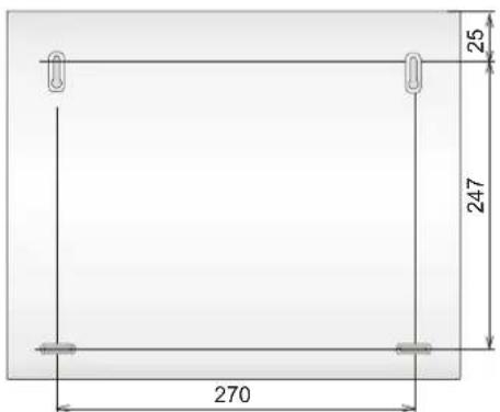
fig. 16 Control panel box dimensions

fig. 17 Control panel box layout
Description: 1. switch mode power supply module; 2. power supply terminal; 3. power supply fuse; 4. back-up battery space; 5. band securing the back-up battery in place; 6. possible hole for cables; 7. external bus connector (OLink; service keyboard); 8. communicator or output module space; 9. box cover tamper contact; 10. control panel main board (more detail see fig. 1); 11. radio module antenna (if installed)
12 Control panel programming sequences
| Function Sequence Options | Factory default | Setting to comply with EN-50131-1 | Notes | ||
| Entering enrollment modeOne wireless device (detector, keypad, keyfob, siren or sub control panel) can be enrolled to each address from 01 to 50.The system offers vacant addresses one by one, if all addresses are occupied no devices can be enrolled.A device enrolled to address 01 to 30 disables the corresponding hard-wired input 01 to 30.In addition to enrollment mode, devices can also be enrolled by keying in their production codes (see 6.42). | 1 | Keys:▲1 and▼ = address scrolling holding 2 = erases the displayed address holding 4 = erases all addresses # = exiting enrollment mode | nothing | · devices enroll by connecting their power (battery) except keyfobs which enroll by pressing & holding a pair of their buttons· an occupied address is indicated by the A indicator being lit· enrolling a device to a new address will move it there | |
| Exit delay time | 20x | x = 1 to 9 (x10 s =10 to 90 s) | 30s | if a final door detector is used, then x is multiplied by 30s instead (i.e. from 30 to 270s) | |
| Entrance delay time | 21x | x = 1 to 9 (x 5 s = 5 to 45 s) | 20s | ||
| Alarm duration time | 22x | x = 1 to 8 (min.), 9=15min | 4 min. | 0=10s (for testing) | |
| PGX function | 23x24x | x in an unsplit system:0 whole system set (ABC) = PG on1 any system part set = PG on2 AB set (not C) = PG on3 Fire alarm = PG on4 Panic alarm = PG on5 Any alarm = PG on (excluding Panic)6 AC dropout = PG on7 PG on/off (by *80 /*81 for PGX and *90/*91 for PGY)8 Single 2 s pulse (keys *8=X, *9=Y) | 7on/off (*80/*81) | x in a split system0 alarm A = PG on1 alarm B = PG on2 entrance delay A == PG on3 entrance delay B = PG on4 A set = X on, B set = Y on5 A panic = X on,B panic = Y on6 Fire = X on,AC dropout = Y on.7 PG on/off (by *80 / *81for PGX and *90 / *91 for PGY)8 Single 2 s pulse (keys *8=X, *9=Y) | |
| PGY function | 1anysystempart set | ||||
| Enablement of telephone number changes in maintenance mode | 25x | 251 = YES 250 = NO | NO | see communicator | |
| Radio interference indication | 26x | 261 = YES 260 = NO | NO | YES | 30 s or longer |
| Radio communication supervision | 27x | 271 = YES 270 = NO | NO | YES | |
| RESET enabled | 28x | 281 = YES 280 = NO | YES | ||
| Master control panel enrollment to a sub control panel for setting (arming) control | 290 | The sequence triggers enrollment. | (Un)setting the master control panel will (un)set the sub control panel.The sub control panel must be in enrollment mode. | ||
| Master code reset | 291 | Returns master code to 1234 | It has no effect on other codes and it is recorded in the control panel memory | ||
| Measuring signal strength | 298 | Activates measurement | arrow keys scroll addresses,# halts measurement. | ||
| Enrolling the control panel to UC, AC or a sub control panel | 299 | The sequence triggers enrollment. | see 6.9 | ||
| Setting (arming) without an access code | 30x | 301 = YES 300 = NO | YES | NO | by keying: A, B, ABC, *1, *2,*3, *4 |
| Triggered detector indication by text on the keypad display | 31x | 311 = YES 310 = NO | YES | allows the display of open windows & doors,to view details press ? | |
| Confirmation of intruder alarmsIn this mode, the triggering of an intruder detector in a set (armed) section will only be recorded to the memory as an unconfirmed alarm and if then followed by the activation of any other intruder detector within 40 minutes,an alarm will be triggered. If the first triggered detector has a DEL reaction and it is not confirmed by any other detector, it will not trigger an alarm after the entrance delay has expired. | 32x | 321 = YES 320 = NO | NO | An alarm can be confirmed by any other intruder detector in any section which is set (armed). | |
| Exit delay beeps | 33x | 331 = YES 330 = NO | YES | The last 5 s faster | |
| Exit delay beeps while partially arming | 34x | 341 = YES 340 = NO | NO | The last 5 s faster(linked to 33x setting) | |
fig. 18 Summary of the programming sequences
fig. 18 continues
| Function Sequence Options | Factory default | Setting to comply with EN-50131-1 | Notes | ||
| Entrance delay beeps | 35x | 351 = YES 350 = NO | YES | ||
| Setting (arming) confirmation by wired-siren chirp | 36x | 361 = YES 360 = NO | NO | IW terminal only | |
| Siren always sounds during audible alarms | 37x | 371 = YES 370 = NO | YES | NO = siren only sounds if the system is completely set (armed) | |
| Wireless-siren alarms enabled (IW & EW) | 38x | 381 = YES 380 = NO | YES | NO = siren disabled | |
| Auto-bypass user approval via the * keyIf a detector is active during setting (arming), the system will automatically bypass it (them), immediately (390), or after keying in *(391) | 39x | 391 = YES 390 = NO | NO | YES | to confirm auto-bypass while exiting Service mode press # twice |
| Final-door detectorsIf this function is used, then Exit & Entrance delay settings are multiplied by 30s. A triggered final-door detector extends the exit delay, de-triggering of the last final-door detector ends the exit delay. | 65x | 0 none1 detectors 01 to 05,2 detectors 46 to 50 | x = 0 | If multiple F. door detectors are used, then triggered state=any of them, non triggered state=all of them | |
| Partial setting (arming) or system splitting | 66x | 0 unsplit system1 partial setting (A, AB, ABC)2 split system A, B & common section C (set if A & B are set) | 0 | ||
| Automatic Summer Time(Daylight Saving Time) | 680x | 6801 = YES 6800 = NO | NO | Changes internal clock + 1h on Apr.1 & -1h on Nov.1 | |
| Pulse reaction of tamper sensorsTamper alarm in response to an increase in the number of triggered tamper sensors | 681x | 6811 ignore permanently triggered tamper sensors, i.e. only react to an increase in the number of triggered tamper sensors6810 react with a tamper alarm to all triggered tamper sensors | X = 0 | Suppresses the indication of permanently triggered tamper sensors | |
| Operating the PG outputs using *8 and *9 | 682x | 6821 = YES 6820 = NO | YES | if yes then arrow keys can also operate PGX | |
| Permanent alarm status display for a set system | 683x | 6831 = YES 6830 = NO | NO | suppresses the 3min. display timeout | |
| Tamper alarm if unset (disarmed) | 684x | 6841 = YES 6840 = NO | NO | YES | |
| Recording PG output activation to memory | 685x | 6851 = YES 6850 = NO | YES | ||
| Engineer reset | 686x | 6861 = YES 6860 = NO | NO | ||
| Social alarm | 687x | 6871 = YES 6870 = NO | NO | ||
| Annual check requirement displayIf enabled then 12 months after exiting Service Mode an annual technical check request is displayed on the keypad unit (mobile phone & ARC notification optional) | 690x | 6901 = YES 6900 = NO | NO | Another time period can be selected by changing the system date before exiting service mode | |
| Only single alarm indicationIf enabled then another intruder alarm can not be triggered during an intruder alarm currently in progress. | 691x | 6911 = YES 6910 = NO | NO | YES | 6911 = no other alarms are reported during an intruder alarm |
| Setting (arming) by service code | 692x | 6921 = YES 6920 = NO | NO | only with the master code holder's approval | |
| Audible panic alarm | 693x | 6931 = YES 6930 = NO | NO | ||
| Higher control-panel receiver-sensitivityExtends the communication range if there is no RF interference | 694x | 6940 = normal6941 = higher | normal | ||
| Access by Code plus CardIf enabled and there is a code and card assigned to the same user, then both of them must be presented for setting (arming) control (in any order). | 695x | 6951 = Code+Card6950 = Code or Card | code or card | YES | |
| Audible 24h intruder alarm | 696x | 6961 = YES 6960 = NO | YES | 0= silent 24h intruder alarm | |
| Service mode only with service + user (master) code | 697x | 6971 = YES 6970 = NO | NO | YES |
fig. 18 continues
| Function Sequence Options | Factory default | Setting to comply with EN-50131-1 | Notes | ||
| Device reactions and section assignment (detectors, key fobs, control panel and keypad inputs)A detector's natural reaction can be INS, DEL or Fire (selectable in the detector)The natural reaction of Control panel & Keypad wired inputs is DELKeyfob natural reactions: (arm), (or ) = UNSET (disarm) and both simultaneously = Panic. If a reaction from 2 to 8 is selected (see opposite), only the key (or and double buttons + (or) will have it. The button has no effect (can still be used for controlling UC/AC receivers).Assignment to sections will only have an effect on partial arming or if the system is split (except PG output control)For partial arming, a pair of keyfob buttons assigned to section:A has the effect:(or SET A, (or SET AB) has the effect:(or SET A, (or SET ABC has the effect:(or ) = SET ABC, (or ) = UNSET ABCIn a split system, a keyfob button pair assigned to section: A=SET/UNSET A, B=SET/UNSET B, C=SET/UNSET ABC | 61nn rs | nn = address 01 to 50r = reaction:0 disabled (incl. tamper sensor)1 Natural - this means:for detectors = selected by DIP switch in the detector, for wired inputs = DELay, for Codes (cards) = SET/UNSET2 Panic3 Fire4 24 hours5 Next DELay6 INSTant7 SET (arm)8 PG control (s: 1=PGX, 2=PGY,3=PGX+PGY)9 SET/UNSET (toggle)s = section 1=A, 2=B, 3=C - has to be entered even if the system is not split and setting (arming)has no meaning. | all Natural in C | When the detector is disabled (r=0), the tamper sensor is not triggered,Natural reaction of control panel wired inputs (or IN keypad input) is delayed (DEL) | |
| Code (card) reactions and section assignmentA code (card) may have the same kind of reaction as devicesAssignment of the code to sections is useful for split systems only. In a split system, a code (card) assigned to C will SET/UNSET all ABC sections. | 62nn rs | ||||
| Enrollment by keying in production codes | 60 n n xxxxxx xx | nn = address 01 to 50, xxxxxxxx = last 8 digits of the production code (below the bar code on the device) | |||
| Automatic Daily Setting/Unsetting schedule (arming/disarming) | 64 n a hh mm | n = action sequence index (0 to 9)a = action:0 no actip1 SET ABC2 UNSET ABC3 SET A4 SET B (if unsplit then AB)5 UNSET A(if unsplit then ABC)6 UNSET B(if unsplit then ABC)hh - hours, mm - minutes | No action | The scheduled actions will happen every day | |
| Changing the service code | 5 NC NC | NC = new code (4 digits) | 8080 | enter NC twice | |
| Go to maintenance mode | 292 | switches to maintenance mode | - | ||
| Setting the internal clock | 4 hh mm DD MM YY | (III)1.1.00 | |||
| Editing keypad textText for device names, code names and PG output names are stored in each individual keypad. | The menu can be entered in Service mode by holding the ? key. Then the internal keypad menu will be displayed. Using the arrows or keys 1 and 7 you can scroll through the menu to Edit text.Press *. Editing mode and the name of the device enrolled to address 01 is then displayed with a flashing cursor on the first text character.Key functions:1 and 7 text scrolling (see table)3 and 9 character-selection (A,B,C,D......8,9,0)4 and 6 cursor control (left/right)2 delete selected character space# exit editing (& save changes) | Device | Only capital letters can be entered this way. If there are multiple keypads, each must be edited individually this way or all of them can be easily programmed via OLink software | ||
13 Programming access codes and cards
| Code name | Amount | Sequence Notes | |
| Service 1 5 NC | NC | Only programmable in Service Mode.NC = new code (must be entered twice) – a card cannot be used.Factory-default service code:8080This code can be changed but not erased.Example:5 4567 4567 | |
| Master 1 | *5 MC NC NC | Only programmable if the disarmed)MC = master code or card (factory default 1234)NC = new code or card entry – a numerical code has to be entered twice, but a card only presented onceEither a code or a card can be prog rammed as a master code (to have both is impossible).The Maste Code can be changed but not erased.The Master Code's reaction is set/unset and it is assigned to all sections.To reset the Master Code to the factory default 1234, enter 291 in Service Mode (this will only affect the Master Code).To make handing over the system to the end user easier, we recommend programming the system card (provided with the control panel) to the master code.Example:*5 1234 and then presenting the card to the keypad's RFID reader | |
| User | 50 | *6 MC nn NC | Only programmable if the system is totally unsetMC = Master Code or card.nn = user code or card position from 01 to 50.NC = new code or card entry.Factory default: all user codes and cards are erased.Each user position can have both a card and a code programmed to it (by using the sequence *6 MC nn NC twice)Each user code can have its own reaction programmed by an installer in Service Mode, and with a split system, codes can be assigned to different sections.Example:*6 1234 12 4345 (code 4345 will be programmed to user position 12)To erase codes/cards enter:*6 MC nn 0000 erases the code and the card in user position nn.*6 MC 00 UC erases the code UC (or card UC) if programmed to any user position.*6 MC 00 0000 erases all user codes and cards in user positions 01 to 50. |
fig. 19 Programming access codes and cards (only in the disarmed state)
Notes:
- Control panel architecture
- Required system configuration
- Preparing the control panel for installation
- Control panel main board
- Main board terminal description:
- Hard-wired inputs on the main board
- Installation of additional hard-wire input modules
- Radio module installation
- Y,X,V communicator module installation
- Control panel memory chip
- Note:
- Wired keypad connection
- Notes:
- Control panel resetting
- Control panel power supply
- Backup battery connection
- Power supply connection
- Powering-up the control panel for the first time
- OASiS wireless devices
- Enrolling wireless devices to the control panel
- Testing enrolled wireless devices
- Signal strength measuring
- Erasing enrolled devices
- Enrolling the control panel to UC and AC modules
- Control panel programming
- Exit delay time
- 20x
- Entrance delay time
- 21x
- Alarm duration time
- 22x
- PGX and PGY functions
- Changing telephone numbers in maintenance mode
- Radio interference indication
- Radio communications supervision
- RESET enabled
- Enrollment to a sub control panel for setting control
- Notes for operating the sub control panel:
- Master code reset
- 291
- Enrollment to other devices (UC, AC)
- Setting (Arming) without an access code
- Triggered-detector indication
- Confirmation of intruder alarms
- Confirmation logic:
- Exit delay beeps
- Exit delay beeps while partially setting (arming)
- Entrance delay beeps
- Setting (arming) confirmed by wired-siren chirp
- Sirens always sound during audible alarms
- Wireless siren alarm enabled (IW and EW)
- Bypass user approval
- Final-door detectors
- 65x
- Description of final-door detector mode:
- Setting (arming) the system with a final-door detector:
- Unsetting (disarming) the system with a final door detector:
- Partial setting (arming) or system splitting
- 66x
- Automatic summer time (daylight saving time)
- Pulse reaction of tamper sensors
- Operating the PG outputs using \* 8 and \* 9
- Permanent alarm status display for a set system
- Tamper alarm if unset
- Recording PG output activation to memory
- Engineer reset
- Social alarm feature
- Annual check notification
- Only single alarm indication
- Setting (arming) by service code
- Audible panic alarm
- Higher control-panel receiver-sensitivity
- Access by code plus card
- Audible 24 hour intruder alarm
- Service mode only with service and user code
- Device reactions and section assignment
- Guidance on programming reactions:
- Code/card reactions and section assignment
- 62nnrs
- Guidance on assigning codes or cards to sections:
- Guidance on code/card reactions:
- Enrollment by keying in production codes
- nn xx..x
- Automatic setting / unsetting schedule
- n a hh mm
- fig. 13 Actions
- Changing the service code.
- NC NC
- Go to maintenance mode
- Setting the internal clock
- hh mm DD MM YY
- Editing keypad text
- Recommended settings
- Operating the system
- The system keypad
- Keypad indicators:
- LCD display
- Keypad display sleep-mode
- Functions beginning with the \* key
- Programming access codes and cards
- Setting and unsetting (arming/disarming) the system
- To set the system from a keypad;
- To unset the system from a keypad:
- Operating the system from an outdoor keypad:
- Maintenance Mode
- In maintenance mode it is possible to:
- Displaying which user/card positions are occupied
- Bypassing devices
- Protecting a car near the system
- Operating/programming the system by PC
- Basic guidance for installers
- Control panel technical specifications
- JA-82R radio module
Brand : Jablotron
Model : JA-83K
Category : Surveillance Camera