JA-60GSM - Surveillance Camera Jablotron - Free user manual and instructions
Find the device manual for free JA-60GSM Jablotron in PDF.


| Type | GSM Dialer Module |
| Compatible Control Panels | JA-60, JA-63, JA-65 |
| Power Supply | 12 VDC, max 1 A (from control panel) |
| GSM Bands | E-GSM/GPRS 900/1800 MHz |
| Transmitted Power | 2 W (GSM900), 1 W (GSM1800) |
| AUX Output | Dry contact, max 100 mA / 60 V |
| SMS Reporting | Up to 8 phone numbers |
| Remote Control Methods | SMS, telephone keypad, GSMLink website |
| Central Monitoring Station | Supports two CMS (Contact ID, SMS, GPRS) |
| Language Options | Multi-language (16 languages) |
| Antenna Gain | +3 dB (standard) |
| LED Indication | On when connected to network, flashing when not |
| Operating Temperature | -10°C to +40°C |
| Safety Standards | EN 50131-1, EN 50136-2-1, EN 60950 |
| EMC Standards | EN 301489-1, EN 301489-7, EN 55022, EN 50130-4 |
| Radio Standards | ETSI EN 301419-1, EN 301511 |
Frequently Asked Questions - JA-60GSM Jablotron
User questions about JA-60GSM Jablotron
0 question about this device. Answer the ones you know or ask your own.
Ask a new question about this device
Download the instructions for your Surveillance Camera in PDF format for free! Find your manual JA-60GSM - Jablotron and take your electronic device back in hand. On this page are published all the documents necessary for the use of your device. JA-60GSM by Jablotron.
USER MANUAL JA-60GSM Jablotron
The JA-60GSM dialer is constructed for the JA-60, 63 and 65 alarm control panels. The dialer is used for communication via GSM. An appropriate GSM provider is chosen according to the inserted SIM card. This Installation manual is intended for the JA-60GSM, version FJ61412.
The GSM module, when installed in the alarm control panel, enables:
- Automatic sending of an event's text messages to up to 8 mobile phones
• Dialing of programmed telephone numbers and playing of an audible warning signal
• Data transfer to one or two Central Monitoring Stations (CMS) - Remote control and programming of the alarm system via SMS instruction messages from a mobile phone or from Jablotron's SMS website
• Remote control and programming of the alarm system using a telephone set keypad (mobile or land line)
• Remote control of an appliance (heating system etc.) via telephone (mobile or land line) - Phone calls and convenient receiving and sending of SMS messages using an SMS-8010 telephone set (optional accessories; except GSM kits e.g. JK-05) attached to the dialer module (via the GSM network)
• Connection of the intercom SP-01 for communication with the premises - Internet connection using the GPRS data transfer
- Programming of the alarm system via ComLink software
- Programming and remote supervision of the alarm system via Jablotron's website www.gsmlink.cz
• Multi-language support (only available via keypad instructions)
1 Installation of the dialer
The JA-60GSM dialer can be installed into the telephone communicator's position in a JA-60, 63 or 65 control panel (either a GSM module or a telephone line communicator module can be used in a control panel – it is not possible to install both simultaneously).
a) Disconnect the control panel's power supply (both AC and backup battery). If the control panel has been previously used before this installation, enter the programming mode before disconnecting the power supply.
b) We recommend you to disable the SIM card PIN code protection before you insert it into the dialer. Use a mobile phone to perform this task (if you have a NOKIA phone, select: Menu, Settings, Security settings, PIN code request, Off). If you insist on usage of the PIN, see section 5.1.
c) Open the SIM card holder (by sliding it in the direction shown in figure 1) and Insert the SIM card into the holder and close it by sliding it back. - see figure 1.
d) Attach the dialer into the control panel case and connect its flat cable to the control panel's main board.
e) Connect the GSM antenna (never switch the power supply on without a proper antenna)
f) Connect a SMS-8010 telephone set to the PHONE connector (or to PHONE terminals) if desired. Only one telephone set can be attached to the dialer. The PHONE output of the dialer should never be connected to any other telephone network.
g) If you use the AUX output to control an appliance, connect its cable to the AUX output terminals (normally open dry contact, max. 100mA / 60V) – see figure 1.
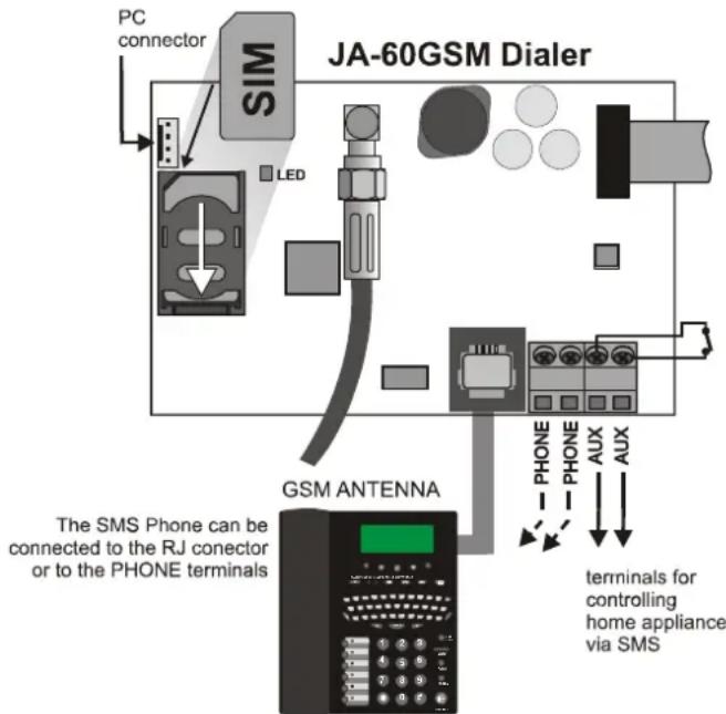
flowchart
graph TD
    A["PC connector"] --> B["SIM"]
    B --> C["LED"]
    C --> D["GSM ANTENNA"]
    D --> E["The SMS Phone can be connected to the RJ connector or to the PHONE terminals"]
    D --> F[" terminals for controlling home appliance via SMS "]
    style A fill:#f9f,stroke:#333
    style B fill:#ccf,stroke:#333
    style C fill:#cfc,stroke:#333
    style D fill:#fcc,stroke:#333
    style E fill:#ffc,stroke:#333
    style F fill:#fcc,stroke:#333
figure 1
Note: if your control panel supports programming of the PgX and PgY outputs for the AUX function (sequences 238 and 239), the appliance can also be controlled wirelessly from the control panel by incorporating a UC-216 or UC-222 receiver module into the system.
h) Reconnect the control panel's power supply (backup battery and AC). The system will show a P, (programming mode). The red LED on the GSM dialer will light permanently (indicating that the module is establishing a connection with the GSM network). The LED will switch off after the connection is successfully established.
If the LED starts flashing, the module was not able to connect to the GSM network. In this case, switch off the control panel's power completely. Remove the SIM card and insert it into a mobile phone to confirm whether it is possible to connect to the network at this location. You can also select a desired network manually if options are available. Ensure that the SIM card does not request a PIN code (optional use with a PIN code is described in section 5.1). Once the SIM card works in the mobile phone, reinsert it into the GSM dialer and repeat step h). If the GSM signal is weak in this area, change the location of the GSM antenna before you try to reestablish the connection.
i) Attach the control panel's cover after the module has connected to the GSM network (LED switched off).
j) Key in 97701 - to set texts of the communicator to English language. (English is the default setting, so you can omit this step.)
k) Enter 971 on the alarm system keypad (while in programming mode) to monitor the GSM signal. The keypad will show a number from 0 to 9 and it will sound a beep every second indicating a new measurement. For proper functioning of the dialer the signal strength should be 3 or higher. Find the best location for the antenna while measuring the signal strength. To switch the system back to programming mode press the N key.
I) Without additional programming you can test the user features of the dialer (phone calls from an attached phone, remote control of the system via a remote phone, remote control of an appliance etc.). See the following description.
m) Set telephone numbers for automatic event reporting and the other selectable features – see part 3.
n) Programming of the GSM dialer is possible by entering programming sequences via the alarm system's keypad (while in programming mode). The most convenient programming method, however is via a connected PC using ComLink software, or by using the www.GSMlink.cz website.
The installed GSM dialer offers many useful features described in detail below, or briefly in table 11. A synopsis is available on the user card. The installer should properly demonstrate the use of the system to the user after installation.
2.1 Phone calls from the attached telephone set
After the GSM module is connected to the GSM network, an attached SMS phone can be used to make calls. If you pick up the phone, you will hear a dial tone. Simply dial the number you want to call (as if you are dialing from a normal fixed line phone). You can also dial the GSM communicator's phone number from another phone, and its attached phone will ring as a normal land line phone would. If it is necessary to communicate with CMS the call from the attached phone will be terminated in 10 minutes.
If there is a busy tone on the attached telephone set, either the line you are calling is busy, or the GSM communicator is busy with previous communication at that moment (for example data transfer to the monitoring station).
You can also use the attached phone keypad to operate the alarm system. By pressing the # key, you can toggle the keypad from telephone mode to alarm system control mode.
Note: some telephone sets are sensitive to the GSM radio signal. For this reason you may hear a characteristic noise in the telephone receiver when calling. If the noise is disturbing, change the location of the phone set (try to keep it as far as possible from the GSM dialer antenna). Usually it is possible to find a suitable location for the phone with a minimal level of interference.
2.2 Remote control of the alarm system by telephone
A system equipped with a GSM dialer can be remotely controlled. From a mobile phone there are two possibilities – either by text instructions sent by SMS or by dialing-in and operating the system via the phone keypad which will operate in the same way as the alarm system keypad. The dialing-in method can also be done from an ordinary landline telephone set.
The following description matches the factory default settings of the communicator. The described features can be greatly modified in the programming mode – see part 4.
2.3 General rules for remote control by SMS instructions
- SMS instructions can be sent from a mobile phone or from an SMS website.
- In SMS, letters are not case-sensitive. Only the basic English alphabet is accepted by the communicator.
- All SMS instruction words must be separated by a space.
- If the % is used all previous text will be ignored. The %% symbol when used in SMS text ends processing – all the following text will be ignored. It is recommended to use this symbol at the end of the instruction if the provider sends some additional text after your message (advertisements etc.).
- Warning: if any incoming SMS includes except a valid system command any extra text which is not separated by % or %% symbols the command will not be executed Examples of SMS:
"Hi, this text will be ignored even if I write ME % MO % Thank you" – Only MO command will be executed
"Hi, MO" – Command in the SMS will be ignored because there is an extra text
- The default command texts can be customized by an installer (see 4.2.2). For example the instruction AUXON can be changed to SWITCH ON HEATING etc.
2.4 Arming by SMS (AM xxxx)
The command AM followed with a valid access code can be used to arm the alarm system. If the system is already armed, the command will have no effect. SMS text to be sent to the dialer: AM*xxxx
xxxx is a valid alarm system access code (Master or user).
* separating character, which can be replaced by a space
Example: Sending AM 1234 will arm the system, which is equivalent to using code 1234 for arming by keypad
Notes:
- According to the default setting, the system confirms command execution with a corresponding SMS reply
- If it is impossible to arm the system – for example if it is in programming mode, you will be notified about the situation by an SMS reply
- If the alarm system is split, the instruction will effect the section which belongs to the access code used *
- If arming without a code is enabled on the control panel, the AM command can be used without any access code. In this case the command performs the same action as the keys F 1 pushed on a keypad.
2.5 Disarming by SMS (DM xxxx)
Command DM followed with a valid access code will disarm the system. If the system is already disarmed, the command will have no effect. SMS text to be sent to the communicator: DM xxxx
xxxx is a valid alarm system access code (Master or user). * separating character, which can be replaced by a space
Example: Sending DM*1234 will disarm the system, which is equivalent to entering code 1234 on a system keypad.
Notes:
- The system confirms disarming with a corresponding SMS reply
- If it is impossible to disarm the system – for example it is in programming mode, you will be notified about the situation by an SMS reply
- If the alarm system is split, the instruction will effect the section which belongs to the access code used*
* If the alarm system is split and a command is used (AM or DM), the user code will effect the system the same way as if the code had been entered from the alarm system keypad – no matter if AM or DM is used (will arm if the system is disarmed and will disarm if the system is armed).
2.6 Mode request by SMS (MO)
Command MO can be used to read the current alarm system mode. The dialer will reply with a reporting SMS to the phone which sent the MO command about status, level of GSM signal, GPRS status, success of transferring data to the CMSs. SMS text to be sent to the dialer: MO
Example: If the system is armed, it will reply to the MO instruction with the SMS: Alarm system reports: Control panel status: Armed,GSM:7,GPRS OK,MS1 NOT,MS2 OK
Note: if you want to protect this command with a password, set your own instruction text including the password – see section 4.2.2
2.7 Last event request by SMS (ME)
Instruction ME can be used to read the last event recorded in the alarm system's memory. The dialer will reply with a reporting SMS. SMS text to be sent to the dialer: ME
Example: After a fire alarm, it will reply to the ME instruction with the SMS: Alarm system reports: Last event: Alarm end Control panel Time: 02.06. 19:48
Note: if you want to protect this command with a password, set your own instruction text including the password – see section 4.2.2.
2.8 Appliance remote control by SMS (AUXON, AUXOFF)
These commands can be used to operate the AUX output (for example the heating in a house). The dialer confirms command execution with an SMS reply.
To switch on the AUX output, send SMS text: AUXON To switch off the AUX output, send SMS text: AUXOFF
Example: to switch on heating send SMS: AUXON
Note: texts of these instructions can be customized and protected with a password – see section 4.2.2. Outputs PgX and PgY can be controlled by SMS commands PGON and PGOFF.
2.9 Remote programming of the alarm by SMS (yyyy PRG seq)
Command PRG can be used to send programming and operating sequences to the alarm system. It has the same effect, as if the sequences had been entered on the alarm system keypad. Type the instruction as:
yyyy \*PRG\* seq,seq,seq,
where
yyyy is the remote access code; factory default setting is 0000 (4 zeros); the code can be changed, see section 5.4
PRG is the command identification
seq are the programming or operating sequences, consisting of characters 0 to 9, F, N. There can be more than one sequence in one SMS. The particular sequences should be separated with a comma or dot. The number of sequences in one SMS is limited by the maximum size of the SMS in the GSM network.
* separating character, which can be replaced by a space
Example: if the control panel is disarmed and its Installer code is 6060, then the duration of the alarm can be programmed to 5 minutes and the acoustic indication of the exit delay can be disabled by sending the following SMS:
0000 PRG F06060,225,330,N
After receiving the SMS command, the control panel will first enter programming mode (F06060) then sequences 225 and 330 will be executed and at the end programming mode will be exited (N).
2.10 Alarm system remote control from a telephone keypad
If you want to operate the alarm system from a phone (mobile or landline), perform the following:
a) Dial the alarm system phone number. The attached telephone will ring
b) If the phone is not answered, the system will answer after 25 seconds - indicated by a short beep
c) Enter the remote access code; factory default is 0000 (4 zeros); to change this code see section 5.4
d) Confirmation sounds indicate the control panel mode: 1 beep = armed, 2 beeps = disarmed, 3 beeps = programming mode, Siren sound = alarm.
e) From this moment the telephone keypad will work as the alarm control panel keypad. The * Key is interpreted as F, the # key as N.
f) Confirmation sounds indicate the control panel mode: 1 beep = armed, 2 beeps = disarmed, 3 beeps = programming mode, Siren sound = alarm.
g) To terminate the connection simply hang up. The connection will also be terminated if there is no entry within 60 seconds.
Notes:
- Remote access from a landline is only possible from a phone using tone dialing (DTMF)
• The reaction of the alarm system to incoming calls can be modified: see section 5.3
- It is impossible to operate the system remotely without a valid remote access code (if used).
2.11 Appliance remote control via a telephone keypad
If you want to operate outputs PgX or PgY (e.g. a household appliance) from a phone (mobile or landline), perform the following:
a) Dial the alarm system number. The attached telephone will ring.
b) If the phone is not answered, the system will answer after 25 seconds - indicated with a short beep.
c) Enter the remote user access code; factory default setting is 1111; to change this code see 5.4.
d) The system will confirm validity of the code with a beep.
e) From this moment you can operate the PgX and PgY outputs (if they are each predefined as phone-controllable) by entering:
*80 to switch off PgX or PgY, or both together,
*81 to switch on PgX or PgY, or both together (continuously).
f) To terminate the connection simply hang up. The connection will also be terminated if there is no entry within 60 seconds.
Notes:
- Remote access from a land line is only possible from a phone using tone dialing (DTMF)
• The reaction of the system to incoming calls can be modified: see section 5.3
- If the system is not allowed to control without code, the control sequence must be complete with a user code:
*8[user code]1 *8[user code]0
- For this function it is necessary that the alarm system supports F 81 and F 80 sequences
- If the dial in function is set (see 3.1.) it is possible to switch ON the PgX or PgY output for two seconds. The phone call is not answered therefore it is free of charge.
2.12 Remote voice communication with premises
If the SP-01 intercom is plug-in to the PHONE terminal (it must not be combined with any phone connected) it is possible to create a one way (talking or listening) communication from an authorized (stored) phone numbers (see. 3.1). Procedure:
a) From an authorized phone dial the JA-60GSM phone number. The SP-01 will ring once and then it will answer the call
b) Potential alarm on the control panel will be terminated
c) You can talk to the premises
d) For switching to the listening mode press 5 on your phone. For switching back to the talking mode press key 2. Or by pressing button 1 it is possible to toggle between talking and listening.
e) Press 0 or hang-up to terminate the call.
Note:
- Only a phone with available DTMF can be used.
3 SMS and audible alarm reports
The factory default settings allow the GSM dialer to send SMS reports and audible warnings when the control panel generates important information (alarms, arming, etc.). It is only necessary to set the telephone numbers which the information should be reported to. To enter these numbers, first enter programming mode.
If you prefer to report more or different events than the factory default provides, see section 4.
3.1 Telephone numbers entering
The dialer has 8 telephone number memories. Each memory has assigned particular SMS reports and/or audible warnings according to the default setting – see table 1.1. By entering a telephone number in to a particular memory location you are selecting what will be reported to this number:
7t xxx...x F0
Where t is a memory location from 1 to 8 xxx...x is a telephone number (max. 20 digits), enter F9 before the number, if you need the + prefix for international calls. To use an attached SMS telephone set, enter code 001 instead of the telephone number. To authorize a phone number for communication with premises via the SP-01 intercom set F8 (#) at the end of the phone number or F7 (*) for dial-in function (see 2.11.).
To disable reporting to a particular number, delete this number memory by entering:
7tF0
where t is a memory from 1 to 8
Report testing:
If you wish to report any alarm, arming and disarming by SMS followed by the notifying call and your mobile phone number is 123456789, then enter 75123456789F0 (while the control panel is in programming mode). Then exit programming mode by pushing the N key. Now you can arm the system and your mobile phone will receive a reporting SMS.
3.2 Installation name in SMS reports
Each reporting SMS message starts with: "Alarm system reports":. You can change this default title text by sending the dialer the following text programming SMS:
yyyy\*TXT\*700,text
where
yyyy is the remote access code; factory default is 0000 (4 zeros); the code can be changed, see 5.4
TXT is the text programming command
700 is the index number on the system text table corresponding to the installation name comma (separator)
text is your own new installation name. A comma or dot cannot be used in the text. A blank space inside the text is a valid character (the dialer ignores spaces before the separator)
* separating character, which can be replaced by a space
Example: If the default code is in the dialer, then sending SMS:
0000 TXT 700, Mr. Diamond's jewelry shop reports:
to the dialer will change the installation name to the above text.
Note: all the SMS texts stored in the dialer can be changed in a similar way, see section 4.2 for details.
| Memory | Entry sequence | Reporting mode for the two corresponding phone numbers: | Notes |
| 1 | 71____F0 | - ALARM SMS if there is any type of alarm in the system (intruder, fire, tamper, panic).- Technical SMS about events in the system. | Only numbers, which can accept SMS, should be entered for the SMS reports (mobile phones, provider's call centers etc.)Audible warnings can be sent both to mobiles and to landlines tooThe communicator can report all possible events from the alarm system, not only the events listed in the table above. See section 4 for details. |
| 2 | 72____F0 | ||
| 3 | 73____F0 | - ALARM SMS if there is any type of alarm- ALARM CALL notifies the called person (if you answer such a call, you will hear an audible warning).- Technical SMS about events in the system. | |
| 4 | 74____F0 | ||
| 5 | 75____F0 | - ALARM, ARMING & DISARMING SMS.- ALARM CALL notifies the called person (if you answer such a call, you will hear an audible warning).- Technical SMS about events in the system. | |
| 6 | 76____F0 | ||
| 7 | 77____F0 | - ALARM CALL notifies the called person (if you answer such a call, you will hear an audible warning). This setting is suitable for notifying landline numbers.- Technical SMS about events in the system. This position is reserved only for the service/installer organization. | |
| 8 | 78____F0 |
4 Customization of SMSs and audible reports
The default text and audible reports sent can be modified.
- The dialer can report all possible events of the alarm system by SMS (see table 4.1.1).
- It is possible to set which events will be reported to which telephone number.
- There are factory default SMS texts available for all possible events and for all possible event sources. All these texts can be edited.
- It is possible to set which events should activate audible warnings.
- The communicator can report all possible events by dialing programmed numbers and playing an audible warning - if the call is answered
- It is possible to change SMS command texts, which are used for remote control of the system.
First enter the programming mode if you are going to use the following programming sequences:
4.1 Events to be reported by SMS
Table 4.1.1 shows the complete list of all possible events in the alarm system together with each corresponding index number. It also shows which events are assigned to which telephone numbers to be reported by SMS. You can make your own setting by using:
81 uu t y
where
uu is the event index from 01 to 31 (see table 4.1.1)
t is a telephone number memory location from 1 to 8
y 0 = reporting disabled, 1 = reporting enabled
Note: SMS reports consist of 4 text parts (installation name, event name, event source name and time) – all of these texts can be edited and customized, see section 4.2 for details. In a single SMS there can be up to 160 characters using ASCI format, or 65 characters using UNICODE format. Exceeding these limits will result in split messages. The event “Internal communication failure” is generated if any of the wireless detectors are lost under RF supervision.
The event “External communication failure” is generated if there is a GSM signal outage longer than 15 minutes. The release of this event is possible when GSM signal monitoring is set to ON.
Example: if you enter 810381 and a Fire alarm is triggered (event index 03) by detector number 1, the following message will be sent to the 8 ^th telephone number: "Alarm system reports: Fire alarm Wireless detector #1 Time: 16.04. 11:16"
4.1.1 Table – SMS report assignments to telephone numbers
| uu | Event | Telephone numbers Event index | |||||||
| 1 | 2 | 3 | 4 | 5 | 6 | 7 | 8 | ||
| 01 | Intruder alarm – instant zone | x | x | x | x | x | x | ||
| 02 | Intruder alarm – delayed zone | x | x | x | x | x | x | ||
| 03 | Fire alarm | x | x | x | x | x | x | ||
| 04 | Panic alarm | x | x | x | x | x | x | ||
| 05 | Wrong access code alarm | x | x | x | x | x | x | ||
| 06 | Alarm after power on | x | x | x | x | x | x | ||
| 07 | Tamper alarm | x | x | x | x | x | x | ||
| 08 | Tamper OK | ||||||||
| 09 | Alarm end | ||||||||
| 10 | Alarm canceled by a user | x | x | x | x | x | x | ||
| 11 | Arming | x | x | ||||||
| 12 | Disarming | x | x | ||||||
| 13 | Partial arming (Home) | x | x | ||||||
| 14 | No code arming | x | x | ||||||
| 15 | External communication failure | x | x | x | x | x | x | x | |
| 16 | External communication recovery | ||||||||
| 17 | Failure | x | x | x | x | x | x | ||
| 18 | Failure recovery | ||||||||
| 19 | AC failure longer than 30 minutes | x | x | x | x | x | x | x | |
| 20 | AC failure | ||||||||
| 21 | AC recovery | ||||||||
| 22 | Battery failure | x | x | x | x | x | x | x | |
| 23 | Battery recovery | ||||||||
| 24 | Enter programming mode | ||||||||
| 25 | Exit programming mode | ||||||||
| 26 | Remote access | ||||||||
| 27 | Remote access – end | ||||||||
| 28 | RF jamming | ||||||||
| 29 | Internal communication failure | x | x | x | x | x | x | x | |
| 30 | Internal communication recovery | x | x | x | x | x | x | x | |
| 31 | Periodic test | ||||||||
The x marks in the table show which events are assigned to which telephone numbers for SMS reporting. If you modify these, we recommend you to mark your settings in the table.
4.2 SMS text editing
The list of SMS texts stored in the dialer consists of texts reported as event reports (installation name, event name and source name) and texts for remote control instructions. All these texts can be changed by the following SMS form:
$$ \text { yyyyTXTy,text,y,text,..... } $$
where
yyyy is the remote access code; default setting is 0000 (4 zeros); the code can be changed, see 5.4
TXT is the text programming command y is the text index (from 1 to 711, see table 4.2.1). , comma (separator)
text is the new customized text string. Neither a comma nor a period (full stop) can be used inside the text. A space inside the text is a valid character (the dialer ignores spaces outside the "text" string)
Note: a single TXT command SMS can change more than one text (limited by the maximum SMS size of the SMS in of the GSM network).
Example: If the factory default code in the dialer is 0000 (four zeros), then sending SMS:
0000*TXT*201, uncle Sam's controller, 202, aunt Mary's controller to the dialer will change the names of remote controller numbers 1 and 2.
4.2.1 Table - complete list of SMS texts
| Text index y | Factory default text | Text index y | Factory default text |
| 1 Intruder alarm – instant zone | 403 | Wireless detector #3 | |
| 2 Intruder alarm – delayed zone | 404 | Wireless detector #4 | |
| 3 Fire alarm | 405 | Wireless detector #5 | |
| 4 Panic alarm | 406 | Wireless detector #6 | |
| 5 Wrong access code alarm | 407 | Wireless detector #7 | |
| 6 Alarm after power on | 408 | Wireless detector #8 | |
| 7 Tamper alarm | 409 | Wireless detector #9 | |
| 8 Tamper OK | 410 | Wireless detector #10 | |
| 9 Alarm end | 411 | Wireless detector #11 | |
| 10 | Alarm canceled by a user | 412 | Wireless detector #12 |
| 11 | Arming | 413 | Wireless detector #13 |
| 12 | Disarming | 414 | Wireless detector #14 |
| 13 | Partial arming (Home) | 415 | Wireless detector #15 |
| 14 | No code arming | 416 | Wireless detector #16 |
| 15 | External communication failure | 501 | User code #1 |
| 16 | External communication recovery | 502 | User code #2 |
| 17 | Failure | 503 | User code #3 |
| 18 | Failure recovery | 504 | User code #4 |
| 19 | AC failure longer than 30 minutes | 505 | User code #5 |
| 20 | AC failure | 506 | User code #6 |
| 21 | AC recovery | 507 | User code #7 |
| 22 | Battery failure | 508 | User code #8 |
| 23 | Battery recovery | 509 | User code #9 |
| 24 | Enter programming mode | 510 | User code #10 |
| 25 | Exit programming mode | 511 | User code #11 |
| 26 | Remote access | 512 | User code #12 |
| 27 | Remote access – end | 513 | User code #13 |
| 28 | RF jamming | 514 | User code #14 |
| 29 | Internal communication failure | 600 | Control panel status: |
| 30 | Internal communication recovery | 601 | Armed |
| 31 | Periodic test | 602 | Disarmed |
| 101 | Control panel | 603 | Exit delay |
| 102 | Subsystem | 604 | Entrance delay |
| 103 | Wireless siren | 605 | Alarm |
| 104 | GSM dialer | 606 | Programming mode |
| 105 | Digital line | 607 | User mode |
| 110 | Master code | 608 | Partially armed |
| 201 | Controller #1 | 609 | Battery failure |
| 202 | Controller #2 | 610 | Tamper alarm |
| 203 | Controller #3 | 611 | Alarm memory |
| 204 | Controller #4 | 612 | System failure |
| 205 | Controller #5 | 613 | Power supply failure |
| 206 | Controller #6 | 614 | Control panel status unknown |
| 207 | Controller #7 | 621 | Time: |
| 208 | Controller #8 | 622 | Last event: |
| 301 | Wired detector #1 | 623 | SMS processing failure. |
| 302 | Wired detector #2 | 624 | Credit unknown |
| 303 | Wired detector #3 | 625 | Text will be inserted by instruction CREDIT (see 5.14) |
| 304 | Wired detector #4 | 650 | SMS processed successfully. |
| 305 | Wired detector #5 | 651 | Wrong SMS processing. |
| 306 | Wired detector #6 | 653 | AUX switched ON |
| 307 | Wired detector #7 | 654 | AUX switched OFF |
| 308 | Wired detector #8 | 700 | Alarm system reports: |
| 309 | Wired detector #9 | 703 | AM |
| 310 | Wired detector #10 | 704 | DM |
| 311 | Wired detector #11 | 705 | MO |
| 312 | Wired detector #12 | 706 | ME |
| 313 | Wired detector #13 | 707 | AUXON |
| 314 | Wired detector #14 | 708 | AUXOFF |
| 315 | Wired detector #15 | 709 | CREDIT |
| 316 | Wired detector #16 | 710 | PGON |
| 401 | Wireless detector #1 | 711 | PGOFF |
| 402 | Wireless detector #2 | ||
4.2.2 Editing of remote control SMS commands
If you change any of the text strings from 703 to 711, the dialer will recognize the new text string as the valid remote control command. E.g., if you change text "MO" (number 705) to "Tell me my alarm status please" it will be possible to read the control panel status by sending the new string as the SMS command. This function helps customers keep the commands secret and protect the dialer against unauthorized operation.
4.3 Assignment of audible warnings to be reported
Table 4.3.1 shows the complete list of all possible events in the alarm system. It also shows which events are assigned to which telephone numbers to be reported audibly. You can make your own setting by:
82 uu t y
where
uu is an event index from 01 to 31
t is a telephone number memory location from 1 to 8
y 0 = reporting disabled, 1 = reporting enabled
4.3.1 Table – audible warning assignments to telephone numbers
The x marks in the table show which events are assigned to which telephone numbers to be reported audibly. If you modify these, we recommend you mark your setting in the table. If there is an alarm, a siren sound will be played, for other events a melody sound will be played.
| Event index uu | Event | Telephone numbers | ||||||||
| 1 2 | 3 4 5 | 6 7 8 | ||||||||
| 01 | Intrude alarm – instant zone x | x | x | x | x | |||||
| 02 | Intruder alarm – delayed zone | x | x | x | x | x | ||||
| 03 | Fire alarm | x | x | x | x | x | ||||
| 04 | Panic alarm | x | x | x | x | x | ||||
| 05 | Wrong access code alarm | x | x | x | x | x | ||||
| 06 | Alarm after power on | x | x | x | x | x | ||||
| 07 | Tamper alarm | x | x | x | x | x | ||||
| 08 | Tamper OK | |||||||||
| 09 | Alarm end | |||||||||
| 10 | Alarm canceled by a user | |||||||||
| 11 | Arming | |||||||||
| 12 | Disarming | |||||||||
| 13 | Partial arming (Home) | |||||||||
| 14 | No code arming | |||||||||
| 15 | External communication failure | |||||||||
| 16 | External communication recovery | |||||||||
| 17 | Failure | |||||||||
| 18 | Failure recovery | |||||||||
| 19 | AC failure longer than 30 minutes | |||||||||
| 20 | AC failure | |||||||||
| 21 | AC recovery | |||||||||
| 22 | Battery failure | |||||||||
| 23 | Battery recovery | |||||||||
| 24 | Enter programming mode | |||||||||
| 25 | Exit programming mode | |||||||||
| 26 | Remote access | |||||||||
| 27 | Remote access – end | |||||||||
| 28 | RF jamming | |||||||||
| 29 | Internal communication failure | |||||||||
| 30 | Internal communication recovery | |||||||||
| 31 | Periodic test | |||||||||
Example: if you enter 820381 and a Fire alarm is triggered (event index 03) the dialer will call the 8^th telephone number and it will play audible warning if the call is answered.
4.4 Temporarily disabling SMS and audible reports
If you need to disable all SMS and audible reports temporarily to all telephone numbers, use the following sequence:
800 all reports disabled the communicator will send neither the alarm SMS nor acoustic warnings
801 all reports enabled the communicator will send the audible reports and SMS messages according to the settings in chapter 4.1.1. and 4.3.1.
802 the communicator will send the preset reports except the events of "arming" and "disarming" by Master code, user codes 1 to 4 and controllers 1 to 4
Default setting: all reports enabled (801).
5 General settings
Enter programming mode if you are going to use any of the following sequences.
5.1 Using a SIM card with a PIN code
It is recommended to use a SIM card with the PIN code protection disabled (this can be done with a mobile phone, see section 1). If you insist on using a PIN code, enter it after the GSM dialer has been powered up using:
70 xxxx F0
where:
JA-60GSM dialer module 6 / 11 MFJ51215
xxxx is the PIN code (4 digits)
Example: if the PIN code is 1234 enter 701234F0
Default setting: 70F0 the PIN code protection is off Note:
If the dialer does not connect to the GSM network after powering up (LED starts flashing), there is a probability that a wrong PIN code was set. In this situation:
enter 70F0 on the control panel keypad when in programming mode (PIN code erasing in the dialer)
- disconnect the control panel's power supply (AC and battery)
remove the SIM card, insert it into a mobile phone and check the PIN code. Check also that it is possible to connect to the desired GSM network at the location of the dialer's GSM antenna.
☐ if you are sure the PIN code is right and the location is covered by a GSM signal, insert the SIM card back in to the dialer, switch the power supply on, enter the PIN code (70 PIN F0) and wait until the communicator connects to the GSM network (LED will turn off).
- If you are going to change the current SIM card in the dialer for another one and the former one used a PIN code, enter programming mode first and enter 70F0 (PIN code erasing in the dialer).
5.2 GSM signal checking
If this function is enabled, the dialer will check regularly whether the GSM signal is available. If it is not available for more than 15 minutes, the system will indicate an external communication failure (failure L).
910 checking disabled
911 checking enabled
Default setting: checking disabled (910)
5.3 Reaction to an incoming call (remote access)
This sequence sets how the dialer will react to incoming calls. This setting is important for remote access by telephone.
93 x where
x = 0 no reaction to an incoming call
x = 1 to 8 will answer after 1=5sec., 2=10sec.,..., 8=40 seconds
x = 9 will answer after the second call = after the 1^st ring is detected, there must be a pause of 10 - 45 seconds. The dialer will answer on the very first ring of the second call. This setting can be used to bypass an answering machine connected to the phone output.
Default setting: 935 – the communicator will answer after 25 seconds
5.4 Remote access code setting
The following sequences are used for programming:
5.4.1 Service remote access code
94 xxxxxxxxx F0
where
xxxxxxxx is the code, it can have 1 to 8 digits
If you enter 94F0 - the code will be erased and the remote access to the alarm system will be not allowed.
Default setting: 0000 (4 zeros)
5.4.2 User remote access code
94 xxxxxxxxx F1
where
xxxxxxxx is the code, it can have 1 to 8 digits
If you enter 94F1 - the code will be erased and user remote access to the alarm system will be not allowed.
Default setting: 1111
5.5 Confirmation SMS reply messages
After the valid processing of an incoming SMS command, the dialer automatically replies to the sender with a confirmation SMS message. This confirmation is selectable:
950 automatic reply is disabled
951 automatic reply is enabled
Note: if the automatic reply is disabled, you can request a reply manually by adding a space and the letter C after the last character of the SMS instruction.
Default setting: 951 – automatic reply is enabled
5.6 Reset to default settings
Entering 96060 will cause the return to the default settings (all telephone numbers will be erased and all unsent data will be erased. For reloading the factory default SMS texts choose the language again by the sequence 97701 (for English) or 9770x according to section 5.18.
5.7 Total reset – all communications disabled
Entering 96061 will erase all of the settings in the dialer's memory and the list of SMSes will be set to default setting.
5.8 One-time dialing-in during programming mode
While the control panel is in the programming mode, you can enable one-time remote access by entering 970. After this code has been entered, the dialer will respond to the first ring of any incoming call. Without requesting the access code, it will enable the calling phone's keypad to be used as the keypad of the alarm system (* = F, # = N).
This mode will be disabled after you dial-in, or after you exit programming mode.
5.9 GSM signal monitoring
Enter 971 on the alarm system keypad (in programming mode) to measure the GSM signal strength. The keypad will show a number from 0 to 9 and it will sound a beep every second indicating a new measurement each time. For proper functioning of the module the signal strength should be 3 or higher. Find the best location for the antenna while measuring the signal strength. To switch the system back to programming mode press the N key.
Note: The standard antenna supplied with the JA-60GSM has a gain of +3dB.
5.10 Attached phone function
The dialer provides a PHONE output to connect an ordinary telephone set. The function of this telephone can be modified by entering:
98 y
| Where | Function |
| y = 0 | An ordinary telephone line is simulated, it is possible to make phone calls (indicated with a dial tone in the receiver) |
| 1 | If you pick up the receiver, the telephone keypad will work as the keypad of the alarm system. It is impossible to make phone calls in this mode (you will hear sounds of the alarm keypad in the receiver) |
| y = 2 | Disabled - the telephone has no function |
| y = 3 | Emergency call – if you pick-up the phone, it will automatically dial the emergency number (see 5.11) |
Notes:
- If y=0 and you pick up the phone, the telephone keypad can be switched to the alarm system keypad mode by pressing the # key.
- If y=3 and you press the * key less than 2 seconds after you pick up the phone, you will hear the dial tone and you can then call any number. If the # key is used the same way, the keypad will switch to the alarm system keypad mode.
Default setting: y = 0 ordinary telephone line is simulated
5.11 Setting the emergency call number
If the attached telephone is programmed for emergency calls (see section 5.10), it dials the emergency number after you pick up the receiver. This number can be entered by:
99 xx...x F0
where:
xxx...x is a telephone number (max. 20 digits), enter F9 before the number if you need + prefix for international calls
Default setting: no phone number is set (99F0)
5.12 Function of attached SMS-8010 phone
The communicator has a telephone connector, which can be used for connection to a SMS-8010 phone. A detail description is in the separate manual enclosed with the SMS-8010 phone. To use an SMS phone enter code 001 instead of the telephone number (see chapter 3.1)
Setting:
- For sending SMSs to mobile phones it is necessary to set SMS center 1 to "1111".
- By sending SMSs to telephone number "001", the central panel can be controlled using SMS instructions
Note:
- Displaying the caller's telephone number (CLIP): The telephone number is shown in the international format (00420212345678).
- If the phone call is made from a JA-60GSM a telephone number of 001 and name of the caller "JA-60GSM" will be displayed.
5.13 Sustain calls for prepaid SIM cards
If a prepaid card is used, the dialer can automatically perform a sustain call if there were no calls within a 3 month period. It will dial the programmed number and after a 10 second call duration, the dialer will hang up. The number, which should be called, can be entered by:
973 xxxxxxxxx F0
where: xxxxxxx is the telephone number (max. 20 digits) – it is recommended to call a time check service, weather reports etc.
5.14 Prepaid SIM cards
The JA-60GSM communicator can send information about the credit balance of a prepaid SIM card. An SMS sent from any of the stored numbers (sequence 7t...) containing the word CREDIT followed by the correct command (different for every provider) will result in sending information about the credit. Please ask your mobile phone provider for more information.
CREDIT \*xxxxx#
where xxxxx is a string, which depends on the GSM provider. Ask your provider for more details
If you want to check the credit regularly use the following sequence.
CREDIT uuu..u xx yyy zz
where: uuu...u is the GSM-provider-defined instruction to be
transmitted to the provider for receiving information about the amount of credit
xx is the time period (in days) between credit checks.
yyy is the minimum acceptable level of credit. A value lower than this threshold triggers a warning SMS.
zz is an index or pointer, measured in characters from the start of the provider message, showing the position of the first digit of the credit value in the information SMS sent by the provider. This allows the GSM dialer to extract the credit value.
If the credit level is lower than the set value (yyy) the event "battery discharged GSM communicator" will be sent to the preset telephone numbers. If the credit is restored the event "battery OK GSM communicator" will be sent to the preset telephone numbers. To disable this function set the time (xx) period to 00.
Note:
- The user is responsible for the level of the credit
- The producer does not recommend the use of prepaid cards.
When automatic credit checking is set to disabled, the user will be unaware of expired credit. Many GSM providers also demand regular credit recharging. Therefore a prepaid SIM card is not recommended.
5.15 Telephone volume
The volume and sensitivity of the attached telephone can be adjusted by:
974x receiver volume
975x microphone sensitivity
where x can be from 1 to 9 (factory default is 5 for both)
If the system is in programming mode, the volume can be adjusted during a phone call.
5.16 GPRS communication setting
GPRS can be used for communication with a www server, for connecting a PC to the internet or for communication with a CMS. GPRS must be activated on the SIM card (for detailed information ask your GSM provider). It is also necessary to set the APN in programming mode in the communicator using ComLink software.
5.17 GSM module reset
Enter 976 to disconnect and connect the GSM module to the GSM network. This function is useful when it is necessary to switch the mobile device off and on (e.g. when the SIM card has been unblocked by the mobile operator).
It is also possible to send the command via SMS in the form yyyy*GSM, where yyyy is service access code. The command is processed independent of the state of the system.
5.18 Language setting
Language of the text used by the communicator can be set by instruction:
977 xx
where:
xx is number of the language – see the following list:
| 01 | EN | English | 09 | PL | Polish |
| 02 | CZ | Czech | 10 | PT | Portuguese |
| 03 | SK | Slovak | 11 | RU | Russian |
| 04 | DA | Danish | 12 | SE | Swedish |
| 05 | FI | Finnish | 13 | TR | Turkish |
| 06 | DE | German 14 | ES | Spanish | |
| 07 | HU | Hungarian | 15 | NL | Dutch |
| 08 | IT | Italian | 16 | CN | Chinese |
Note:
- Set the language before editing the text in the system (change of the language will change the text to the factory default).
- Set language will not be changed when reset is performed.
- Language setting can NOT be performed via the ComLink software or the GSMLink.
- This feature is only available for communicators equipped with SW version FJ61412 or higher.
- Do not use *.jag files for language setting.
Example: by setting 97702 the Czech language will be set.
Factory default : 97701 = English
6 Web server remote access
6.1 System programming
The GSMLink server allows a user/installer to read and change the control panel and dialer configurations. Data transfer is achieved by sending an SMS or GRPS data. The web site allows the following programming:
• control panel settings
- dialer settings
• editing of SMS reports
• monitoring station settings
The web site is also able to read the event memory of the control panel. The amount of data sent by SMS is optimized to minimize costs. Alternatively GPRS data transfer can be used, but this must be activated on the SIM card.
6.2 Web site registration
System registration can be performed in two ways:
The www.gsmlink.cz website – to register your system use the registration code printed on the warranty certificate (the code has a form xxxx-xxxxx-xxxx and it is a unique for each system). The dashes (-) must be included when registering.
By mobile phone – when the alarm system is in programming mode, enter 972 xxxx F0 on the alarm system keypad (xxxxx is your mobile phone number). After a moment you will receive an SMS with the registration code and the system will register on the web server.
7 Central Monitoring Station communication settings
The dialer can report events to two different Central Monitoring Stations (CMS). Each CMS has its own setting sequences that differ in parameter p (p=1 for CMS1 and p=2 for CMS2). The dialer uses Ademco Contact ID format and it is also equipped for the future use of GPRS data transfers. The product is able to report events to a CMS based on either landline or GSM data transfer.
7.1 CMS phone number entry
Primary and back up telephone numbers can be entered for each CMS:
Primary number: 01 p xx....x F0 Back up number: 02 p xx....x F0
where:
xxx...x is a telephone number, max. 20 digits p 1=CMS1, 2=CMS2
Example: 123456789 can be entered as the CMS2 primary number by entering: 01 2 123456789 F0
Note: The IP address can be set a similar way. For example the IP address 192.168.1.123 on port 08080 can be set by entering 01 2 F8 129 168 001 123 8080, where F8 (#) introduces the IP address, which must always have 12 numbers, and the port 5 numbers.
CMS phone number erasure is possible by entering 01pF0 or 02pF0.
There will be no data transfer to a CMS if its numbers are erased.
Default setting: No phone number set
7.2 Account ID setting
A CMS uses this ID number for alarm system identification:
03 p zzzz F0
where:
zzzz is the account ID number (z = numbers from 0 to 9 or A=F1, B=F2, C=F3, D=F4, E=F5 a F=F6)
p 1=CMS1, 2=CMS2
Default setting: ID is 0000 for both CMSs
7.3 Format setting
This sequence is used to select the communication format:
04 p x
where:
p 1=CMS1, 2=CMS2
x protocol type – see table
| Protocol Type x | ||
| Contact ID DTMF | 0 | |
| Jablotron SMS | SMS type | 1 |
| Jablotron GPRS | GPRS type | 2 |
Default setting: Contact ID for both CMSs
7.4 Events to be reported to CMS
There are 31 types of events, which can be reported to each CMS – see table 7.4.1. This sequence sets which events should be reported to CMSs.
05 p uu y
where
p 1 = CMS1, 2 = CMS2
uu events index – see table 7.4.1
y 0 = report disabled, 1 = report enabled
Default setting: all reports are disabled
7.4.1 Table - complete list of events to be reported to CSM
| Events index uu | Events description |
| 01 | Intruder alarm – instant zone |
| 02 | Intruder alarm – delayed zone |
| 03 | Fire alarm |
| 04 | Panic alarm |
| 05 | Wrong access code alarm |
| 06 | Alarm after power on |
| 07 | Tamper alarm |
| 08 | Tamper OK |
| 09 | Alarm end |
| 10 | Alarm canceled by a user |
| 11 | Arming |
| 12 | Disarming |
| 13 | Partial arming (Home) |
| 14 | No code arming |
| 15 | External communication failure |
| 16 | External communication recovery |
| 17 | Failure |
| 18 | Failure recovery |
| 19 | AC failure longer than 30 minutes |
| 20 | AC failure |
| 21 | AC recovery |
| 22 | Battery failure |
| 23 | Battery recovery |
| 24 | Enter programming mode |
| 25 | Exit programming mode |
| 26 | Remote access |
| 27 | Remote access – end |
| 28 | RF jamming |
| 29 | Internal communication failure |
| 30 | Internal communication recovery |
| 31 | Periodic test |
7.5 CMS re-dialing pause setting
If the dialer is activated it attempts to make a connection (alternating between the primary and the backup telephone number). If it is not possible to make a connection, a pause is initiated. After this pause the dialer will attempt again. The pause length can be set in the following way:
06 p t
where
t pause duration x 5 minutes (1 = 5 minutes, 2 = 10
min,..., 9 = 45 minutes)
p 1 = CMS1, 2 = CMS2
Default setting: 5 minutes for both CMSs
7.6 Interval of periodic test
The periodic test for checking the CMS link is set by activating event No 31. The following sequence sets the time length from the last reported event to the moment when the periodic test report should be transferred.
07 p hhmm
where
p 1 = CMS1, 2 = CMS2
hh hours
mm minutes
Default setting: The periodic test report is sent 24 hours after the last reported event.
7.7 Disabling CMS communication
If you need to disable all CMS reports temporarily, you can do this, while retaining your settings:
0 0 p 0 all reports to CMS p disabled
0 0 p 1 all reports to CMS p enabled
Default setting: all CMS reports disabled.
7.8 CMS 2 as a back up for CMS1
CMS 2 can serve as an optional back-up for CMS if data transfer to CMS1 fails. When the first event is transferred to the backup monitoring station (CMS2) an event "tel. line #1 communication fault" will be reported.
080 CMS1 and CMS2 are two independent stations
081 CMS 2 works as a back up for CMS 1.
When 081 is selected, CMS 2's settings are used only in the case of CMS 1 transfer failure.
Default setting: two independent CMSs.
7.9 Storing the event "data to CMS sent" into the event memory
By this sequence it is possible to disable recording of the event that indicates that data to a CMS has been sent to the list of event in the control panel.
Programming sequences:
090 The CMS data transfer event is not recorded
091 The CMS data transfer event is recorded
Default setting: The CMS data transfer event is recorded
8 The modem function
The GSM communicator can also be used as an external modem for accessing the Internet (GPRS format). It is necessary to have GPRS activated in the SIM card and to have a connection cable connected to the COM port of the PC. Support for MS Windows operating systems can be found on the enclosed CD. The modem can only be used when all CMS reports, SMSs and system calls have been executed.
When the modem is used:
- It is possible to use the attached telephone, the internet connection will be temporally suspended
- Received SMSs are stored and they will be processed after modem disconnection
- The modem will be disconnected if an alarm or an arming event occurs
9 Additional information
9.1 Priorities for event reporting:
If the dialer is activated to send an event report it will:
- send information to CMS1 (trying primary and back up numbers twice) if programmed
- send information to CMS2 (trying primary and back up numbers) if programmed
- send SMS reports (1 ^st telephone number, 2 ^nd telephone number,... 8 ^th tel. number)
- send audible reports (1 ^st telephone number, 2 ^nd telephone number,... 8 ^th tel. number) – each number is only called once, whether it is answered or not
- if the attempt to send a report to a CMS has not been successful, the dialer will try to resend it after the re-dialing pause (sequence 06px). The dialer will make three attempts at sending event reports to a CMS, i.e. it will wait (according to the setting 06px) twice for the re-dial pause. Only a new event will result in an additional attempt to call the CMS.
If any event is triggered which should be reported to a CMS while the alarm system is being remotely accessed by phone, the report will be sent after remote access has finished.
If a user cancels an alarm, all reports, which have not been sent yet, will be deleted, except for CMS reports.
9.2 The LED on the dialer PCB
• LED flashing means the dialer has not entered the GSM network
• LED flashing (3x) – the communicator (modem) is controlled by a PC.
- LED being on means– communication with a GSM network
- connecting to the GSM network
- the dialer is calling
– the dialer is sending an SMS
9.3 Entering programming mode
- The dialer will finish the current CMS connection (the attached phone will ring shortly to confirm this)
- The current audible warning is interrupted immediately
- SMSs and audible warnings, which remain unsent before entering programming mode, are erased – they will not be sent after exiting programming mode
- Unsent event reports to a CMS are erased only in the case of a telephone number, account ID or communication format change
• Information about the end of fault events is transferred to the monitoring station during programming mode
• Changes of setting will take affect after exiting programming mode
9.4 The master code holder can change the following parameters
- Telephone numbers 1 – 7 (see section 3.1)
- SMS and audible warning transfers (see section 4)
- Change of remote user code
• One-time dialing in
• Measuring of GSM signal - Attached phone functionality
• Telephone number for emergency calls
10 Technical specifications
power 12VDC / max. 1A – provided by the alarm control panel GSM bands E-GSM/GPRS 900/1800MHz
transmitted power 2 W for GSM900, 1 W for GSM1800
AUX output dry contact, max. 100mA / 60V
comply with EN 50131-1, EN 50136-2-1, 2-3, 2-4
security grade 2 (low to medium risk)
environmental class II indoor-general (-10 to 40°C)
safety EN 60950
EMC EN 301489-1, EN 301489-7, EN 55022, EN 50130-4
radio characteristics ETSI EN 301419-1, EN 301511
Caller line identification presentation (CLIP) ETSI EN 300 089 V3.1.(2000-12)
Can be operated according to commission decision 2000/299/EC
Hereby, Jablotron Ltd., declares that this JA-60GSM is in compliance with the essential requirements and other relevant provisions of Directive 1999/5/EC.

Original of the conformity assessment can be found at the web page www.jablotron.cz, section Technical support.
Note: Although this product does not contain any harmful materials we suggest you to return the product to the dealer or directly to the producer after usage.
11 Brief list of programming sequences
| Function | Sequence | Options | Factory default |
| Tel. numbers for SMS and audible reports | 7t xxx..x F0 | t = memory from 1 to 8xxxx = tel. number (max.20 digits), F9="+" | blank |
| Event SMS reports 81 uu t y | uu = events index from 01 to 31t = memory from 1 to 8y=0 disabled, y=1 enabled | t=1&2 alarm SMSt=3&4 alarm SMS + audiblet=5&6 alarm+arming SMS + audiblet=7&8 audible alarm only | |
| Event acoustic reports 82 uu t y | |||
| SMS and audible reports SW 80 y | y=0 disabled, y=1 enabled, y=2 (enabled with restrictions) | enabled | |
| GSM signal checking 91 y y=0 disabled, y=1 enabled dis | abled | ||
| Incoming call reaction 93 x | x = 0 no reactionx = 1 to 8 answer after 5 to 40 secondsx = 9 answer after the 1string of the 2ndcall | after 25 seconds | |
| Service remote access code | 94 xxxxxxxx F0 | xxxxxxxxx = code, it can have form 1 to 8 digits deleting - 94F0 - remote access is not possible | 0000 |
| User remote access code | 94 xxxxxxxx F1 | xxxxxxxxx = code, it can have from 1 to 8 digits deleting 94F1 - remote access is not possible | 1111 |
| Confirmation SMS reply | 95 y | y=0 disabled, y=1 enabledif disabled, end instruction with C to get the reply | enabled |
| Reset | 96060 | Reset to factory default settings | |
| Reset & no reports | 96061 | Reset to factory default settings & all reports disabled | |
| Immediate codeless dialing-in | 970 | If entered while in programming, you can dial-in after the 1string without the access code | |
| Measuring of GSM signal | 971 | If entered while in programming, it shows GSM signal strength (from 0 to 9) | |
| Volume adjustment of the connected phone | 974x975x | Level adjustment of received and outgoing signal (from 1 to 9) | 5 - medium level |
| GSM Module Reset | 976 | If entered while in programming mode, the GSM module will be disconnected from and connected to the GSM network. It is also possible to send the command via SMS in the form yyyy*GSM. | |
| Language setting | 977 xx | xx=01 to 16 where: 01=EN, 02=CZ, 03=SK, 04=DA, 05=FI, 06=DE, 07=HU, 08=IT, 09=PL, 10=PT, 11=RU, 12=SE, 13=TR, 14=ES, 15=NL, 16=CN | English |
| Attached phone function | 98 y | y=0 telephone line y=2 no functiony=1 alarm keypad y=3 emergency call | telephone line |
| Emergency call number | 99 xxxxxx F0 | xxxxxx = tel. number (max.20 digits), F9="+" | erased |
| CMS telephone numbers | 0y p xxxxx F0 | y=1 primary number, y=2 back up numberp=1 CMS1, p=2 CMS2xxxx = tel. number (max.20 digits), F9="+" | all erased |
| Account ID | 03 p zzzz F0 | p=1 CMS1, p=2 CMS2zzzz account ID, z=0 to 9 or A=F1, B=F2, C=F3, D=F4, E=F5 and F=F6 | 0000 for both CMSs |
| CMS protocol | 04 p x | p=1 CMS1, p=2 CMS2x=0 CID, x=1 SMS, x=2 GPRS | CID for both CMSs |
| Events to report | 05 p uu y | p=1 CMS1, p=2 CMS2uu = events index from 01 to 31y=0 disabled, y=1 enabled | all reports disabled |
| CMS redialing pause | 06 p t | p=1 CMS1, p=2 CMS2t=1 to 9 (x 5minutes) | 5 minutes |
| Periodic test interval | 07 p hh mm | p=1 CMS1, p=2 CMS2hh mm hours minutes | 24hr. after the last report |
| CMS reports SW | 00 p y | p=1 CMS1, p=2 CMS2y=0 disabled, y=1 enabled | disabled for both CMSs |
| CMS2 as a backup of CMS1 | 08 y | y=0 two independent CMSy=1 CMS2 is a back up for CMS1 | two independent CMS |
| Storing the event “data to CMS sent” into the event list | 09 y y=0 ... disable , y=1 ... enable | Enable | |
- Installation of the dialer
- Phone calls from the attached telephone set
- Remote control of the alarm system by telephone
- General rules for remote control by SMS instructions
- Arming by SMS (AM xxxx)
- Notes:
- Disarming by SMS (DM xxxx)
- Mode request by SMS (MO)
- Last event request by SMS (ME)
- Appliance remote control by SMS (AUXON, AUXOFF)
- Remote programming of the alarm by SMS (yyyy PRG seq)
- yyyy \*PRG\* seq,seq,seq,
- PRG F06060,225,330,N
- Alarm system remote control from a telephone keypad
- Appliance remote control via a telephone keypad
- Remote voice communication with premises
- Note:
- SMS and audible alarm reports
- Telephone numbers entering
- 7t xxx...x F0
- Report testing:
- Installation name in SMS reports
- yyyy\*TXT\*700,text
- TXT 700, Mr. Diamond's jewelry shop reports:
- Customization of SMSs and audible reports
- Events to be reported by SMS
- uu t y
- SMS text editing
- Editing of remote control SMS commands
- Assignment of audible warnings to be reported
- uu t y
- Table – audible warning assignments to telephone numbers
- Temporarily disabling SMS and audible reports
- General settings
- Using a SIM card with a PIN code
- xxxx F0
- GSM signal checking
- Reaction to an incoming call (remote access)
- Remote access code setting
- Service remote access code
- xxxxxxxxx F0
- User remote access code
- xxxxxxxxx F1
- Confirmation SMS reply messages
- Reset to default settings
- Total reset – all communications disabled
- One-time dialing-in during programming mode
- GSM signal monitoring
- Attached phone function
- Setting the emergency call number
- Function of attached SMS-8010 phone
- Setting:
- Sustain calls for prepaid SIM cards
- xxxxxxxxx F0
- Prepaid SIM cards
- CREDIT \*xxxxx#
- CREDIT uuu..u xx yyy zz
- Telephone volume
- GPRS communication setting
- GSM module reset
- Language setting
- Web server remote access
- System programming
- Web site registration
- Central Monitoring Station communication settings
- CMS phone number entry
- Account ID setting
- p zzzz F0
- Format setting
- p x
- Events to be reported to CMS
- p uu y
- CMS re-dialing pause setting
- p t
- Interval of periodic test
- p hhmm
- Disabling CMS communication
- CMS 2 as a back up for CMS1
- Storing the event "data to CMS sent" into the event memory
- The modem function
- Additional information
- Priorities for event reporting:
- The LED on the dialer PCB
- Entering programming mode
- The master code holder can change the following parameters
- Technical specifications
- Hereby, Jablotron Ltd., declares that this JA-60GSM is in compliance with the essential requirements and other relevant provisions of Directive 1999/5/EC.
Brand : Jablotron
Model : JA-60GSM
Category : Surveillance Camera