JA-65X - Surveillance Camera Jablotron - Free user manual and instructions
Find the device manual for free JA-65X Jablotron in PDF.


| Product Type | Surveillance Camera |
| Brand | Joblotron |
| Model | JA-65X |
| Resolution | 1080p (1920 x 1080) Full HD |
| Night Vision | Up to 30 meters infrared |
| Field of View | 90° diagonal |
| Motion Detection | Yes, with adjustable sensitivity |
| Two-Way Audio | Built-in microphone and speaker |
| Storage | MicroSD card slot (up to 128GB) |
| Connectivity | Wi-Fi 2.4 GHz, Ethernet (RJ45) |
| Power Supply | DC 12V / 1A (adapter included) |
| Dimensions | 7.0 x 7.0 x 12.0 cm |
| Weight | Approximately 300 g |
| Weather Resistance | IP66 rated (outdoor use) |
| Mounting | Wall or ceiling mount bracket included |
| Compatibility | iOS and Android app (Joblotron Viewer) |
| Maintenance | Clean lens with soft cloth; check connections periodically |
| Safety | Do not expose to extreme temperatures; use supplied power adapter |
| Spare Parts | Power adapter, mounting kit, Ethernet cable (available separately) |
Frequently Asked Questions - JA-65X Jablotron
User questions about JA-65X Jablotron
0 question about this device. Answer the ones you know or ask your own.
Ask a new question about this device
Download the instructions for your Surveillance Camera in PDF format for free! Find your manual JA-65X - Jablotron and take your electronic device back in hand. On this page are published all the documents necessary for the use of your device. JA-65X by Jablotron.
USER MANUAL JA-65X Jablotron
The JA-65X digital communicator is designed for JA-63 and JA-65 alarm control panels. If the 65X module is installed, the control panel can communicate with a Monitoring Station, send voice messages, SMS messages and dial a numeric Pager as well as communicate with a remote PC. A standard analog telephone line (type TNV 1-3) must be connected to the module for these functions.
1 Installation of the digital telephone communicator
- Use the provided telephone cable to connect the telephone line to the IN jack on the X module (see diagram)
- Connect a telephone, fax or other phone operated device to the OUT jack, marked with a phone symbol
- When the control panel is in normal stand-by mode, the phone line and any attached device will operate as normal
Note: The communicator must be plugged directly to a telephone line socket. All other devices (telephone, facsimile machine, modem etc.) should be connected to the communicator output.
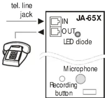
2 Voice & SMS messages setting
A control panel equipped with the X module can automatically send 2 voice and 5 short text messages (or dial a Pager). The most convenient programming of the dialer is via a connected PC using the Comlink software. Programming can also be performed manually from the keypad:
- Enter the programming mode (F 0 Service Code, factory default = 6060), indicated by „P“
- Any unfinished programming sequence can be terminated by pressing the N key.
- To exit the programming mode, press the N key („P“ will turn off). If any fault is indicated when you try to exit the programming mode, the control panel will inform you about the problem.
- Telephone numbers and messages can also be set up in the User Mode when enabled (see installation manual of the control panel).
2.1 Telephone numbers for voice message
sending
sequence: 7xxx....xxFy
Store telephone numbers for voice message by entering: 7 xx... xx F y
where:
xx...xx = telephone number
y = memory number from 1 to 4
A telephone number can have a maximum of 16 digits. A pause can be entered by F0
Example: to store tel. number 0 123456 to memory no. 2 enter: 7 0 F0 12345 F2
Note: enter a pause (F0) after the last digit of a number which is calling a mobile phone. This way the number will be called only once and the dialer will not check the line signals (some mobile phone systems do not generate standard telephone line signals).
Digital communicator JA-65X 1/7 MFM53102
To delete a telephone number enter: 7 F0 Fy
where:
$$ y = \text { memory number from } 1 \text { to } 4 $$
note: entering 7 F0 F0 will erase all tel. numbers, including the SMS settings
When activated, the dialer will disengage all other devices hooked up to the phone line. It will then, one by one, call all programmed numbers and play the user recorded message which corresponds to the event. If the dialer makes a successful connection to a programmed number, it will not call that number again. If the number is busy, the dialer will make 3 more attempts to call it. Empty tel. number memories are skipped. If all memories are empty, the dialer is completely disabled. If the dialer is also programmed to communicate with a monitoring station, the data will first be sent to the monitoring station.
Factory default setting: all telephone numbers are deleted.
2.2 Automatic SMS sending
sequence: 7xxx....xxF5
If Jablotron's SMS server service is provided in your country (check with your distributor), the following setting allows the control panel to send alarm text messages (SMS) automatically to a desired mobile phone:
7 xx...x F9 yy.....y F7 00F9 F7zz..z F5
where:
xx...x = telephone number of the SMS server (check with your distributor if this service is provided in your country)
F9 = separator (recognition of server's reaction)
yy...y = mobile phone number (where the SMS should be sent to)
F7 = event code separator
00F9 = automatic event code - control panel will insert there a digital code representing the alarm (depends on setting in section 2.4)
F7 = ID separator
zz..z = optional ID number which will be sent as a part of the SMS (ending). ID distinguishes which alarm system sent the SMS). If ID is not required, do not enter it
F5 = storing of the sequence to memory 5 (32 digits can be stored to memory 5 as a maximum - separators F9 and F7 takes only 1 digit each).
How the SMS server works: when activated, the control panel dials the SMS server. After the connection is established, it sends telephone number of the mobile phone, to which the SMS should be sent. Then the control panel specifies what happened by a digital code and in the end the ID number is transferred (if programmed). In this moment the SMS server makes corresponding text message and this message is sent to the GSM network.
Example: If SMS server number is 483559876, SMS should be sent to number 606123456 and ID number of the installation is 41 enter: 7 483559876 F9 606123456 F7 00F9 F7 41 F5
Deleting of automatic SMS sending – to erase SMS sending enter: 7 F0 F5
Note: memory 5 can also be used to dial a Pager instead of SMS sending. To dial a Pager enter 7 xx..x F9 zzz....z F5 where xx..x is number of the provider, zz...z is number of the pager and code of the message (check with a local Pager provider for details). Pause in the dialing can be entered with F0., with F7 and with F8. Pager dialing can be deleted with 7 F0 F5.
Factory default setting: SMS sending (Pager dialing) is erased.
2.3 Voice message(s) recording
sequence: 8x
You can record two different voice messages (10 sec. each). Depending on the setting in section 2.4, a particular message will be sent under different situations. Recording of the messages:
a) enter 85 on the keypad
b) press and hold push button on the X module
c) speak towards the module (max. 10 s)
d) release the button, message will play back
This results in the recording of message number 1. To record message 2 enter 86 in step a)
If you prefer sending only one, but longer, message (20 sec.), record message by entering 84 in step a). By programming as described in section 2.4 you can specify which alarms will trigger the sending of a message.
Notes:
- Make the messages brief and clear. The dialer repeats the message to each called number for 40 seconds.
- The voice messages are stored in non-volatile memory and can be changed when ever you want to by repeating the above steps.
- The existing messages can be played by momentarily pressing the push button on the X module (or by entering F9 while in stand by mode).
2.4 Triggering of voice and SMS messages
sending
sequences: 9 y x
With sequences 91x to 95x you can select which alarms will trigger the telephone dialer to call and what will be sent.
Enter: 9 y x
where:
| y | Alarm | x | reaction | |
| 1 | Panic – silent 0 no reaction | |||
| 2 | Intruder 1 voice1 and SMS | |||
| 3 | Fire 2 voice 2 only | |||
| 4 | Tampering | 3 | SMS | only |
| 5 | Technical trouble |
Notes:
- Final texts of alarm SMS are generated by the SMS server (providers computer) – based on the digital code sent by the alarm system (check with provider for more details)
- If only one long voice message was recorded by using code 84 as described in section 2.3, then this message will be sent when x=1 or x=2
• Voice messages are sent step by step to all telephone numbers programmed as described in section2.1 - SMS message is sent to a mobile phone number programmed as described in section 2.2
Example: if the dialer should send an SMS and voice message 1 when intruder or panic alarm is triggered, voice message 2 in the case of fire and only an SMS in the case of technical alarm, enter: 911 921 932 943
Factory default setting: all alarms will trigger sending of voice message 1 and SMS (911, 921, 931, 941, 951).
2.5 Dialing method
sequence: 90x
Enter:
901 for tone dialing
900 for pulse dialing (this option is blocked for some countries)
Note: this dialing method setting is also valid for Central monitoring station communications.
Factory default: tone dialing
2.6 Telephone line checking
sequence: 99x
If this function is enabled, the dialer will check regularly if the telephone line is ready to make a phone call. If the line is not ready for more than 15 minutes, the keypad will indicate a telephone line failure (failure L). A non-working telephone line or a phone conversation or Internet connection longer than 15 minutes can cause a fault.
options:
9 9 1 checking enabled
990 checking disabled
Note: this setting is also valid when the dialer is used for Monitoring station communications as well as remote PC access
Factory default setting: checking disabled
2.7 Telephone dialer testing
sequence: 89
After entering code 89 the dialer will call all programmed numbers and will play voice message 2. It will also send a SMS message if programmed. The telephone line signals will be audible from the control panel's built in speaker during the test (if the dialer is triggered by an alarm in normal operation, it will call silently).
If you prefer testing with voice message 1 enter code 88. Testing can be terminated with the N key.
3 To enable a remote computer to dial in
When the user or installer wants to dial in to the installation from their computer or a remote JA-60E keypad via a JA-60U modem (see section 6), the following parameters should be programmed.
The most convenient programming is via a connected PC using the Comlink software. Programming can also be performed manually:
- Enter the programming mode when disarmed (F 0 Service Code, factory default 6060), indicated by a "P"
- Any unfinished programming sequence can be terminated by the N key.
- To exit the programming, press the N key ("P" will turn off).
Dialing in parameters
| Function | sequence | options | factory d. |
| Incoming call reaction | 0 5 x | 0=never1= second call2-6 = after ringNo. 2 - No.6 | disabled |
| Remote access code(8 digits) | 0 7xxxxxxxxx | any 8 digitscode | 00000000 |
3.1 Reaction to an incoming call
sequence: 05
This sequence sets how the communicator will react to incoming calls on the telephone line. This setting is important for remote access. Enter: 05x
where: x = 0 - never answer
1 - answer after second call = after 1 or 2 rings are detected, there must be a pause of 10 - 45 seconds. The dialer will then answer on the very first ring of the second call. This setting can be used to bypass an answering or facsimile machine connected to the same line. This "Second Call" feature is supported by the Comlink software and also by the JA-60E keypad.
2 to 6 - answer after 2^nd to 6^th ring
Notes: Remote access connection can also be enabled by the alarm system user (regardless of the above setting) by entering 89 while in the user mode, when the phone rings. If you use another telephone set on the same telephone line, it should be switched to the tone dial mode.
Factory setting: 0 = never answer
3.2 Remote access code setting
sequence: 07
In order to access the panel remotely, it is necessary to authorize the access with an 8-digit access code. This code is compared with the one programmed in the control panel. If the caller tries to access the panel with another code, the connection will be terminated immediately. A wrong code alarm will be triggered on the control panel after the 5^th unsuccessful attempt to dial in. Store your access code to the control panel by entering: 0 7 xxxxxxxx
where:
x x ..... x - any 8 digits access code
Factory setting: 00000000
4 Central monitoring station communication setting
This part of the manual is intended only for specialists involved in monitoring. We recommend to use a computer equipped with Comlink program for complete setting of the monitoring station communication.
Changes of the setting can also be performed manually using the keypad:
- Enter programming mode when disarmed (F 0 Service Code, factory default 6060), indicated by a "P".
To exit programming press the N key ("P" will turn off).
Central monitoring station communication parameters
| Sequence Description Factory default setting | |||||
| 0 001 xx to0 198 xx | Reporting codes table (see part 5)where: x = 0 - 9,F0 = A_h,F1 = B_h,F2 = C_h,F3 = D_h,F4 = E_h,F5 = F_h if 00 is set, the event is not reported | 00 | For all events | ||
| 0 2 xxxx | Account ID code (4 digits, for 3/1 and 3/2 formats the structure is 0xxx) x = 0 - 9 (hexadecimal codes can be used too - see above) | 0000 | |||
| 0 3 xy Protocol x:0 = Ademco Slow1 = Ademco Fast2 = Telemax3 = Franklin4 = Radionics2300 | 5 = Radionics 14006 = DTMF 23007 = Surgard8 = AdemcoExpress9 = Contact ID | Format y:0 = 3/1 (xxx R)1 = 3/2 (xxx rc)2 = 4/1/1 (xxxx Rn)3 = 4/2 (xxxx rc) | 90 | Contact ID | |
| 0 4 x | Re-dialing pause, x = 1 - 9 (x 10 min.) | 1 | 10 minutes | ||
| 0 6 xx..xFy | CMS phone numbers xx...x to memory y (1 and 2), pause = F0 | erased | |||
| 0 9 6060 | Communicator reset to factory default settings | ||||
Notes:
Some of the protocols are not standardized and some manufacturers of Monitoring Station receivers use different parameters in some of their protocols. Therefore Jablotron cannot guarantee full compatibility with all Central Monitoring Station receivers.
If the connection with the Monitoring Station is not available, the events are queued in the communicator's memory and are transmitted in one burst as soon as the connection is established. All events are reported to the Monitoring Station in the same order as they happened.
Once communication has started, it can not be interrupted unless the control panel is switched to the programming or to the user mode. For example, if the user causes a false alarm and then cancels it, both events are sent to Monitoring Station.
Events occurring while the control panel is in the programming or user mode are reported to the Monitoring Station after the closing of these modes. (They are stored in the memory and reported together with reporting codes describing the change of operation modes.)
When the dialer is activated, the communication to the monitoring station has the highest priority (voice and SMS messages are sent later with lower priority). A User or Installer can interrupt the digital dialer communication by entering the User mode or Programming mode. Reset of the control panel has no influence to the digital communicator's settings (it is reported to the Monitoring station as an event).
The RESET of the digital communicator itself (sequence 09 6060), the change of the Monitoring Station's telephone numbers, the change of an account number code or the change of a format setting will erase all the reporting codes queued in the communicator's memory. However the events remain stored in the control panel's internal memory.
Jablotron recommends use of the MS-350 monitoring station with ComGuard SW.
Digital communicator JA-65X 3/7 MFM53102
4.1 Reporting codes setting
sequences: 00 and 01
These sequences can be used to program the report codes for all possible events. Depending on the used protocol and format, different amounts of data should be entered. The complete report code programming table is shown in section 5. The setting sequence structure is as follows: 0 x x x r c
where:
$$ \mathbf {x x x} = \text { event number (from 001 to 198) } $$
$$ \begin{array}{r c l} \text {rc} & = & \text {report code (two digits). For 3 / 1 and 4 / 1 / 1 formats} \ & & \text {only the first digit of the report code is used (R).} \ & & \text {Codes should be entered in a hexadecimal} \ & & \text {format, with numbers higher than 9 beginning} \ & & \text {with the F key: A_{h} = F0 B_{h} = F1 C_{h} = F2 D_{h} =} \ & & \text {F3 E_{h} = F4 F_{h} = F5} \end{array} $$
If the reporting code 00 is programmed, the event will not be reported to the Monitoring Station.
Notes:
- Abbreviation "Rc" is used in the report code programming table for the major events group. Only the first digit of this group of codes is transmitted when formats 3/1 or 4/1/1 are used. Other formats use both digits of the "Rc" and "rc" report codes.
-
The Contact ID (CID) is an automatic protocol. If you enter any report code other than zero for a major event (Rc), all events of this type will be transmitted automatically including all details regarding the event source. Internal structure of the CID protocol is shown in part 1.1. This protocol provides the most in-depth data for the monitoring station and its use is recommended by Jablotron.
-
The Surgard protocol has 4/2 structure plus one more digit which is generated automatically (see 4.3)
- If the control panel is split and only one section is armed, then a partial arming report code is sent. If all sections are armed, a complete arming report code is sent. If the system was completely armed and only one section is disarmed, the disarming report code will be sent and then it will be followed by the partial arming report code.
- The pulse formats are not capable to report zero and numbers above 15. For this reason events in zone 16 or in a subsystem are reported to the Monitoring Station as events in zone 10. This means that from the point of view of the monitoring station zone 10 also covers zone 16 and the subsystem if used. This problem does not exist in the CID protocol.
- If the system is arming while there is a bypass, partial arming will be reported to the CMS (also stored to the internal memory)
Factory setting: 00 for all events
4.2 Account ID code setting
sequence: 02
This sequence is used for the alarm system identification by a Monitoring Station. The sequence structure: 02 x x x x
where:
xxxx - account ID code ( x are numbers from 0 to 9 or hexadecimals).
When using only three-digit codes (formats 3/1 and 3/2) enter a zero in the first position. The communicator will then ignore it (example - 0123)
Note: Changing of the account code erases the internal communicator's memory of non reported events and sends a „Reset“ reporting code (051) to the Monitoring Station. If pulse formats are used, zero is transmitted as A_h
Factory setting: 0000
4.3 Protocol and Format setting
sequence: 03
This sequence is used to select the communication protocol and format. Its structure is as follows: 03 x y
where:
x - protocol (0 - 9, see table bellow)
y - format (0 - 3 see table on right)
Notes:
| Protocols | ||||||
| x | Name | Hand-shake | Data | Kiss off | Speed | format |
| 0 | Ademco Slow (Silent Knight) | 1400Hz | 1900Hz | 1400Hz | 10bps | Next table |
| 1 | Ademco Fast | 1400Hz | 1900Hz | 1400Hz | 14bps | Next table |
| 2 | Telemax | 2100Hz | 1650Hz | 2100Hz | 10bps | Next table |
| 3 | Franklin | 2300Hz | 1800Hz | 2300Hz | 20bps | Next table |
| 4 | Radionics 2300 | 2300Hz | 1800Hz | 2300Hz | 40bps | Next table |
| 5 | Radionics 1400 | 1400Hz | 1900Hz | 1400Hz | 40bps | Next table |
| 6 | DTMF 2300 | 2300Hz | DTMF | 2300Hz | DTMF | Next table |
| 7 | Surgard* | 2300Hz | DTMF | 2300Hz | DTMF | 4/3 |
| 8 | Ademco express* | Dual tone | DTMF | 1400Hz | DTMF | 4ID/2 |
| 9 | Contact ID* | Dual tone | DTMF | 1400Hz | DTMF | CID |
* fixed format, "y" is arbitrary (0 is recommended)
| Formats | |||
| y | format | reports | structure |
| 0 | 3/1 | Major events only | xxx R |
| 1 | 3/2 | All events | xxx rc |
| 2 | 4/1/1 | Major events with autom. source identification | xxxx Rn |
| 3 | 4/2 | All events | xxxx rc |
xxxx = account number
R = major event code (only first digit counts)
rc = detailed event code (two digits)
n = source identification (generated automatically)
| Surgard protocol has structure: xxxx E rc, where E is a group identifier (generated automatically) | ||
| E | Event | Note |
| 1 | Fire | |
| 2 | Panic | |
| 3 | Alarm | General |
| 4 | Arming | Incl. Partial |
| 5 | Disarming | |
| 6 | Failure | Power failure, RF jamming ... |
| 8 | Report | Enter/Exit service mode ... |
| 9 | Restore | End of alarm, panic ... |
| A | Test | 24 hour test |
- Some Monitoring Station receivers do not support all formats.
- Logic of the format marking - 4/2 means that an account code has 4 digits and an event report code has 2 digits.
- Changing of a format erases the internal communicator's memory of non reported events and sends a "Reset" reporting code (051) to the Monitoring Station.
Factory setting: 90 (Contact ID)
4.4 Re-dialing pause setting
sequence: 04
If a dialer is triggered it attempts to make a connection (alternating between the primary and the backup telephone number). If it is not possible to make a connection after 8 attempts, a pause is initiated. After this pause the dialer will attempt again. If any event triggers the communicator during the pause, the pause ends immediately. The pause length can be set in the following way: 0 4 x
where:
x – time multiplied by 10 minutes (from 1 to 9, example 3 = 30 minutes)
Factory setting: 1 = 10 min.
4.5 CMS phone number entering
sequence: 06
Central monitoring station modem phone numbers can be stored by entering the following sequence: 0 6 x x .... x F y
where:
xx...x = Central Monitoring Station phone number (up to 16 digits)
y = 1 for primary phone number memory 2 for back up phone number memory
Pause (3 sec.) can be inserted into the telephone number by entering F0. It is also possible to insert the * tone by F7 or the # tone by F8 if requested for DTMF dialing.
Example: number 02 123456 as main Monitoring Station number is entered with 06 02 F0 123456 F1.
Phone number erasing: 0 6 F 0 F y
where:
y = 1 to erase the primary telephone number 2 to erase the back up telephone number
Note: Changing of a phone number erases the internal communicator's memory of non reported events and sends a "Reset" reporting code (051) to the Monitoring Station.
Factory setting: both numbers are erased
4.6 Digital communicator reset
sequence: 096060
By entering this code the factory default settings of all parameters are restored in the digital dialer. All phone numbers, reporting codes, account codes etc. are erased. This reset doesn't effect the voice dialer's settings. The reset sequence is: 0 9 6060
Note: All communicator settings are stored in non-volatile memory and remain unchanged even after switching off the power supply.
5 Central Monitoring station report codes table
A two digit report code rc (00 to FFh) can be set for every event. If 00 is programmed as a report code, that event will not be reported.
The major events group is marked by Rc. When formats 3/1 or 4/1/1 are used, only 16 of these major events are reported to the Monitoring Station. This makes it necessary to only program the R digits. The second digit does not count. Zero can not be used in the pulse protocols. For Contact ID protocol, program code 11 for major events (Rc) which you want to report and the system will generate all details regarding the event automatically including the events source details (see part 5.1).
| N. | Event Code | |
| 001 | Arming with remote control N.1 Rc | |
| 002 | Arming with remote control N.2 Rc | |
| 003 | Arming with remote control N.3 Rc | |
| 004 | Arming with remote control N.4 Rc | |
| 005 | Arming with remote control N.5 Rc | |
| 006 | Arming with remote control N.6 Rc | |
| 007 | Arming with remote control N.7 Rc | |
| 008 | Arming with remote control N.8 Rc | |
| 009 | Arming with master code Rc | |
| 010 | Arming with user code N.1 Rc | |
| 011 | Arming with user code N.2 Rc | |
| 012 | Arming with user code N.3 Rc | |
| 013 | Arming with user code N.4 Rc | |
| 014 | Arming with user code N.5 Rc | |
| 015 | Arming with user code N.6 Rc | |
| 016 | Arming with user code N.7 Rc | |
| 017 | Arming with user code N.8 Rc | |
| 018 | Arming with user code N.9 Rc | |
| 019 | Arming with user code N.10 Rc | |
| 020 | Arming with user code N.11 Rc | |
| 021 | Arming with user code N.12 Rc | |
| 022 | Arming with user code N.13 Rc | |
| 023 | Arming with user code N.14 Rc | |
| 024 | Partial arming Rc | |
| 025 | Quick arming without code Rc | |
| 026 | Disarming with remote control N.1 Rc | |
| 027 | Disarming with remote control N.2 Rc | |
| 028 | Disarming with remote control N.3 Rc | |
| 029 | Disarming with remote control N.4 rd | |
| 030 | Disarming with remote control N.5 rd | |
| 031 | Disarming with remote control N.6 rd | |
| 032 | Disarming with remote control N.7 rd | |
| 033 | Disarming with remote control N.8 rd | |
| 034 | Disarming with master code rd | |
| 035 | Disarming with user code N.1 rd | |
| 036 | Disarming with user code N.2 rd | |
| 037 | Disarming with user code N.3 rd | |
| 038 | Disarming with user code N.4 rd | |
| 039 | Disarming with user code N.5 rd | |
| 040 | Disarming with user code N.6 rd | |
| 041 | Disarming with user code N.7 rd | |
| 042 | Disarming with user code N.8 rd | |
| 043 | Disarming with user code N.9 rd | |
| 044 | Disarming with user code N.10 rd | |
| 045 | Disarming with user code N.11 rd | |
| 046 | Disarming with user code N.12 rd | |
| 047 | Disarming with user code N.13 rd | |
| 048 | Disarming with user code N.14 rd | |
| 049 | Entering of the programming mode Rc | |
| 050 | Exiting the programming mode Rc | |
| 051 | Communicator Reset Rc | |
| 052 | Initial AC powering Rc | |
| 053 | Alarm after initial AC powering Rc | |
| 054 | General battery trouble Rc | |
| 055 | General battery trouble end Rc | |
| 056 | Control panel battery trouble Rc | |
| 057 | Control panel battery trouble end Rc | |
| 058 | Zone alarm 1 Rc | |
| 059 | Zone alarm 2 rd | |
| 060 | Zone alarm 3 rd | |
| 061 | Zone alarm 4 rd | |
| 062 | Zone alarm 5 rd | |
| 063 | Zone alarm 6 rd | |
| 064 | Zone alarm 7 rd | |
| 065 | Zone alarm 8 rd | |
| 066 | Zone alarm 9 rd |
| 067 | Zone alarm 10 | rc | |
| 068 | Zone alarm 11 | rc | |
| 069 | Zone alarm 12 | rc | |
| 070 | Zone alarm 13 | rc | |
| 071 | Zone alarm 14 | rc | |
| 072 | Zone alarm 15 | rc | |
| 073 | Zone alarm 16 | rc | |
| 074 | Wrong access code alarm | Rc | |
| 075 | Zone tamper 1 | Rc | |
| 076 | Zone tamper 2 | rc | |
| 077 | Zone tamper 3 | rc | |
| 078 | Zone tamper 4 | rc | |
| 079 | Zone tamper 5 | rc | |
| 080 | Zone tamper 6 | rc | |
| 081 | Zone tamper 7 | rc | |
| 082 | Zone tamper 8 | rc | |
| 083 | Zone tamper 9 | rc | |
| 084 | Zone tamper 10 | rc | |
| 085 | Zone tamper 11 | rc | |
| 086 | Zone tamper 12 | rc | |
| 087 | Zone tamper 13 | Rc | |
| 088 | Zone tamper 14 | Rc | |
| 089 | Zone tamper 15 | Rc | |
| 090 | Zone tamper 16 | Rc | |
| 091 | Keypad tamper | Rc | |
| 092 | Control panel tamper | Rc | |
| 093 | Siren tamper | Rc | |
| 094 | Zone fault 1 | Rc | |
| 095 | Zone fault 2 | Rc | |
| 096 | Zone fault 3 | Rc | |
| 097 | Zone fault 4 | Rc | |
| 098 | Zone fault 5 | Rc | |
| 099 | Zone fault 6 | Rc | |
| 100 | Zone fault 7 | Rc | |
| 101 | Zone fault 8 | Rc | |
| 102 | Zone fault 9 | Rc | |
| 103 | Zone fault 10 | Rc | |
| 104 | Zone fault 11 | Rc | |
| 105 | Zone fault 12 | Rc | |
| 106 | Zone fault 13 | Rc | |
| 107 | Zone fault 14 | Rc | |
| 108 | Zone fault 15 | Rc | |
| 109 | Zone fault 16 | Rc | |
| 110 | Keypad fault | Rc | |
| 111 | Control panel fault | Rc | |
| 112 | Siren fault | Rc | |
| 113 | Zone alarm end 1 | Rc | |
| 114 | Zone alarm end 2 | Rc | |
| 115 | Zone alarm end 3 | Rc | |
| 116 | Zone alarm end 4 | Rc | |
| 117 | Zone alarm end 5 | Rc | |
| 118 | Zone alarm end 6 | Rc | |
| 119 | Zone alarm end 7 | Rc | |
| 120 | Zone alarm end 8 | Rc | |
| 121 | Zone alarm end 9 | Rc | |
| 122 | Zone alarm end 10 | Rc | |
| 123 | Zone alarm end 11 | Rc | |
| 124 | Zone alarm end 12 | Rc | |
| 125 | Zone alarm end 13 | Rc | |
| 126 | Zone alarm end 14 | Rc | |
| 127 | Zone alarm end 15 | Rc | |
| 128 | Zone alarm end 16 | Rc | |
| 129 | Zone tamper end 1 | Rc | |
| 130 | Zone tamper end 2 | Rc | |
| 131 | Zone tamper end 3 | Rc | |
| 132 | Zone tamper end 4 | Rc | |
| 133 | Zone tamper end 5 | Rc | |
| 134 | Zone tamper end 6 | Rc |
| 135 | Zone tamper end 7 | Rc | |
| 136 | Zone tamper end 8 | Rc | |
| 137 | Zone tamper end 9 | Rc | |
| 138 | Zone tamper end 10 | Rc | |
| 139 | Zone tamper end 11 | Rc | |
| 140 | Zone tamper end 12 | Rc | |
| 141 | Zone tamper end 13 | Rc | |
| 142 | Zone tamper end 14 | Rc | |
| 143 | Zone tamper end 15 | Rc | |
| 144 | Zone tamper end 16 | Rc | |
| 145 | Keypad tamper end | Rc | |
| 146 | Control panel tamper end | Rc | |
| 147 | Sren tamper end | Rc | |
| 148 | Zone fault end 1 Rc | ||
| 149 | Zone fault end 2 Rc | ||
| 150 | Zone fault end 3 Rc | ||
| 151 | Zone fault end 4 Rc | ||
| 152 | Zone fault end 5 Rc | ||
| 153 | Zone fault end 6 Rc | ||
| 154 | Zone fault end 7 Rc | ||
| 155 | Zone fault end 8 Rc | ||
| 156 | Zone fault end 9 Rc | ||
| 157 | Zone fault end 10 | Rc | |
| 158 | Zone fault end 11 | rc | |
| 159 | Zone fault end 12 | rc | |
| 160 | Zone fault end 13 | rc | |
| 161 | Zone fault end 14 | rc | |
| 162 | Zone fault end 15 | rc | |
| 163 | Zone fault end 16 | rc | |
| 164 | Keypad fault end | rc | |
| 165 | Control panel fault end | rc | |
| 166 | Sren fault end | rc | |
| 167 | Telephone line trouble | Rc | |
| 168 | Telephone line trouble end | Rc | |
| 169 | Control panel failure | Rc | |
| 170 | End of control panel failure | Rc | |
| 171 | Periodic test (24 hr. from last com.) | Rc | |
| 172 | AC failure (in 30 min. after failure) | Rc | |
| 173 | AC failure end | Rc | |
| 174 | RF jamming | Rc | |
| 175 | Wrong code alarm end | Rc | |
| 176 | RF jamming end | Rc | |
| 177 | Panic alarm from remote control N.1 | Rc | |
| 178 | Panic alarm from remote control N.2 | rc | |
| 179 | Panic alarm from remote control N.3 | rc | |
| 180 | Panic alarm from remote control N.4 | rc | |
| 181 | Panic alarm from remote control N.5 | rc | |
| 182 | Panic alarm from remote control N.6 | rc | |
| 183 | Panic alarm from remote control N.7 | rc | |
| 184 | Panic alarm from remote control N.8 | rc | |
| 185 | Master code panic alarm | rc | |
| 186 | User code panic alarm | rc | |
| 187 | Panic alarm end from rem. contr. 1 | Rc | |
| 188 | Panic alarm end from rem. control N.2 | rc | |
| 189 | Panic alarm end from rem. control N.3 | rc | |
| 190 | Panic alarm end from rem. control N.4 | rc | |
| 191 | Panic alarm end from rem. control N.5 | rc | |
| 192 | Panic alarm end from rem. control N.6 | rc | |
| 193 | Panic alarm end from rem. control N.7 | rc | |
| 194 | Panic alarm end from rem. control N.8 | rc | |
| 195 | Master code panic alarm end | rc | |
| 196 | User code panic alarm end | rc | |
| 197 | Subsystem panic alarm | Rc | |
| 198 | Subsystem panic alarm end | Rc |
5.1 Internal structure of Contact ID protocol
The data in the CID protocol has following standardized structure:
XXXX 18 Q XYZ 01 CCC
where XXXX is the account code of the installation, 18 is the code identification (identical for all events), Q is a number from 1 to 3, XYZ is the event number, 01 is the subsystem number, CCC event source details (see the table below).
| JA-63/65 event no. | Q XYZ | Event description | possible source in JA-63 or JA-65 | ||||||
| C | S | c | A | j | L | d | |||
| 058 | 1 110 Fire alarm | x | x | ||||||
| 113 | 3 110 Fire alarm end | x | x | ||||||
| 177 | 1 120 Panic alarm | x | x | ||||||
| 058 | 1 120 Panic alarm from a detector | x | |||||||
| 197 | 1 120 Panic alarm in the subsystem | x | |||||||
| 187 | 3 120 End of the panic alarm | x | x | ||||||
| 113 | 3 120 End of the panic alarm from a detector | x | |||||||
| 198 | 3 120 End of the subsystem panic alarm | x | |||||||
| 058 | 1 130 Intruder alarm in an instant zone | x | |||||||
| 113 | 3 130 End of the intruder alarm in an instant zone | x | |||||||
| 058 | 1 134 Intruder alarm in a delayed zone | x | |||||||
| 113 | 3 134 End of the intruder alarm in a delayed zone | x | |||||||
| 075 | 1 137 System tamper alarm | x | x | x | x | ||||
| 129 | 3 137 All system tampers OK | x | x | x | x | ||||
| 074 | 1 138 Wrong access code alarm | x | x | ||||||
| 175 | 3 138 End of a wrong access code alarm | x | x | ||||||
| 053 | 1 140 Alarm after powering of the control panel | x | |||||||
| 075 | 1 144 Detector tamper alarm | x | |||||||
| 129 | 3 144 All detector tampers OK | x | |||||||
| 094 | 1 300 Failure (blown fuse in control panel or other general failure) | x | x | x | x | x | |||
| 052 | 3 300 Control panel powering | x | |||||||
| 148 | 3 300 No failure in the system | x | x | x | x | x | |||
| 172 | 1 301 AC failure | x | |||||||
| 173 | 3 301 AC switched on | x | |||||||
| 054 | 1 302 Problem with power in an item | x | x | x | |||||
| 056 | 1 302 Back up battery failure in the control panel | x | |||||||
| 057 | 3 302 End of the back up battery failure | x | |||||||
| 055 | 3 302 End of the problem with power in the item | x | x | x | |||||
| 051 | 1 305 Reset | x | x | ||||||
| 049 | 1 306 Entering of programming or user mode | x | x | x | |||||
| 050 | 3 306 End of programming or user mode | x | x | x | |||||
| 058 | 1 330 Subsystem alarm | x | |||||||
| 167 | 1 354 Tel. line failure | x | |||||||
| 169 | 1 354 Failure of communication in the digital bus | x | |||||||
| 168 | 3 354 End of tel. line failure | x | |||||||
| 170 | 3 354 End of a communication failure in the digital bus | x | |||||||
| 174 | 1 355 RF jamming | x | |||||||
| 176 | 3 355 End of RF jamming | x | |||||||
| 094 | 1 380 Detector failure | x | |||||||
| 148 | 3 380 End of all detector failures | x | |||||||
| 094 | 1 381 Wireless item communication lost | x | x | x | x | ||||
| 148 | 3 381 Wireless item communication reestablished | x | x | x | x | ||||
| 054 | 1 384 Detector power problem | x | |||||||
| 055 | 3 384 End of the detector power problem | x | |||||||
| 026 | 1 401 Disarming | x | x | x | |||||
| 001 | 3 401 Complete arming | x | x | x | |||||
| 024 | 3 402 Partial (Home) arming | x | x | x | |||||
| 025 | 3 408 No code arming | x | x | x | |||||
| 171 | 1 602 Monitoring station communication testing (in 24 hr.) | x | |||||||
×
×
[Non-Text]
×
×
×
Event sources specification in the Contact ID protocol:
| JA-63/JA-65 source | mark | code CCC |
| Wireless sensor | S | 001 to 016 |
| Sensor | 201 to 216 | |
| Controller | c | 401 to 408 |
| User code | 501 to514 | |
| Control panel | C | 701 |
| Wireless siren | A | 711 |
| Sub control panel | J | 721 |
| Tel. Line | L | 731 |
| Digital bus | D | 741 |
6 Remote access to the system
The JA-60U modem can be used for the remote connection of the control panel to a personal computer with Comlink software or a remote JA-60E keypad using a standard telephone line. It is necessary to know the remote control access code for the system (see 3.2).
Details on how to use the JA-60E keypad remotely can be found in the JA-60E manual.
A personal computer connected remotely works the same way as when it is wired directly to the control panel (see also installation manual of the control panel). Only downloading or uploading of extensive data (like event list downloading, digital communicator setting etc.) takes a slightly longer time compared to a direct PC connection to the control panel.
6.1 Establishing connection with a remote control panel by computer
Start Comlink SW on a computer equipped with a JA-60U modem. The dialing dialog requires the following data:
- telephone number of the called control panel
• dialing method (tone or pulse) - control panel's remote access code (must be identical as code programmed in the control panel - 8 digits)
- optional bypassing of answering machine (if this option was programmed in the control panel); if the connection can not be established, try to enter "space" after the last digit
- optional call back feature, if you want the control panel to call your computer back (that way the end user's telephone will be charged for the remote access communication)

"Dialing in" dialog of the Comlink software
7 Specification
Digital communication to:
• a monitoring station,
- 5 SMS messages or Pager dialing,
- 2 voice messages, modem communication with a remote PC (ComLink SW + JA-60U modem),
- remote keypad access with JA-60E and JA-60U
Monitoring station formats
Contact ID, Ademco, Telemax, Franklin, Radionics, SurGard, DTMF2300, (198 reports codes)
can be connected to analogue interfaces TBR 21/1998, EG 201 121 V1.13/2000, AS/ACIF S002/2001 (Australia)
CE Hereby, Jablotron Ltd., declares that this JA-65X is in compliance with the essential requirements and other relevant provisions of Directive 1999/5/EC. Original of the conformity assessment can be found at the web page www.jablotron.cz, section Technical support.

Note: Although this product does not contain any harmful materials we suggest you to return the product to the dealer or directly to the producer after usage.
- Installation of the digital telephone communicator
- Voice & SMS messages setting
- Telephone numbers for voice message
- where:
- To delete a telephone number enter: 7 F0 Fy
- Automatic SMS sending
- Voice message(s) recording
- Notes:
- Triggering of voice and SMS messages
- Dialing method
- Enter:
- Telephone line checking
- options:
- Telephone dialer testing
- To enable a remote computer to dial in
- Reaction to an incoming call
- Remote access code setting
- Central monitoring station communication setting
- Reporting codes setting
- Account ID code setting
- Protocol and Format setting
- Re-dialing pause setting
- CMS phone number entering
- Phone number erasing: 0 6 F 0 F y
- Digital communicator reset
- Central Monitoring station report codes table
- Internal structure of Contact ID protocol
- Remote access to the system
- Establishing connection with a remote control panel by computer
- Specification
Brand : Jablotron
Model : JA-65X
Category : Surveillance Camera