
44132 - Thermostat HUNTER - Free user manual and instructions
Find the device manual for free 44132 HUNTER in PDF.


| Brand | Hunter |
| Model | 44132 |
| Product Type | Thermostat |
| Dimensions (approx.) | 4.5 x 4.5 x 1 inches |
| Weight (approx.) | 0.5 lbs |
| Power Source | 2 AA alkaline batteries (1.5V each) or 24V AC system |
| System Compatibility | Conventional oil, gas, electric, hot water, single-stage heat pumps, multi-stage heat pumps |
| Maximum Load | 1 amp at 24V AC |
| Programmable | Yes (scheduling feature) |
| Stage Types | Single or multi-stage |
| Heat Pump Support | Yes (with auxiliary heat) |
| Fan Control | Yes (G terminal) |
| Common Wire (C) Required | Optional |
| Display | Basic LCD |
| Battery Backup | Yes (AA batteries) |
| Installation Tools Required | Phillips screwdriver (#2) |
| Wiring Terminals | R, RC, RH, Y, Y1, Y2, G, W, W1, W2, O, B, C, L, Aux/E |
| Safety Features | Overcurrent protection, line voltage incompatibility warning |
| Maintenance | Replace batteries annually, keep clean |
| Technical Support | USA: 1-888-830-1326, Canada: 1-866-268-1936 |
| Warranty | Not specified in manual |
Frequently Asked Questions - 44132 HUNTER
User questions about 44132 HUNTER
0 question about this device. Answer the ones you know or ask your own.
Ask a new question about this device
Download the instructions for your Thermostat in PDF format for free! Find your manual 44132 - HUNTER and take your electronic device back in hand. On this page are published all the documents necessary for the use of your device. 44132 by HUNTER.
USER MANUAL 44132 HUNTER
Gathering Tools and Warnings

This thermostat is compatible with most conventional oil, gas, electric, hot water systems, single stage, and multi-stage heat pumps. This thermostat will not control line voltage systems.
You will need the following tools to complete your installation:
• Phillips Screwdriver (#2)
- Two 1.5V (AA) size alkaline batteries
Take note of these warnings and cautions before proceeding:
- Read all installation instructions before beginning installation! If you still need assistance after reading this manual, call out Technical Support at 1-888-830-1326.
- Do not disconnect the wires from your old thermostat until all wires have been properly labeled. You must label all wires properly because wire color may not indicate the function of the wire.
- All wiring must be done in accordance with local code and ordinances.
- Always turn power off to your furnace/compressor before the installation process. Failure to do so could result in damage to your thermostat and/or your heating and cooling system. Do not restore power until your installation is complete.
- This thermostat is designed for use with 24V AC/millivolt systems with a maximum of 1 amp. Higher amp or line voltage systems will cause damage to your system and increase the risk of fire.
Old Thermostat Removal

natural_image
Illustration of a hand holding a grid-based interface element (no text or symbols visible)- Turn off power to your compressor and furnace.
- Remove the cover to your existing thermostat. Some thermostats may have screws or other locking devices that must first be removed. Once the wallplate is exposed, locate the wire terminals and try to identify the wire designations. If the wire terminals are not visible, they may be connected to the back of the wallplate. Look for any additional screws, tabs, or locking devices to remove the wallplate. See Figure 1. If you are still unable to find the terminals for the wires, it may be necessary to contact the manufacturer of the original thermostat.

Figure 1.
Labeling Your Wires
Use the table in Figure 2. to write down your wire colors and the letter designations on the old thermostat. This will allow you to keep a record of your old thermostat's wiring configuration should you need to refer to it at a later time. This will also help our Technical Support Department determine your system type and proper wiring, should you need to contact them. Wire color does not indicate the function of the wire, this is being used only to help determine which wire has what letter designation.
| Wire Color Wire letter | |
Figure 2.
Conventional
| RH | RH | |
| RC, R | RC | |
| Y, Y1 | Y | |
| G, F | G | |
| W, W1 | W | |
| W2 | W2 | |
| Y2 | Y3 | |
| C | C | |
| A | A |
Figure 3a.
After writing down the wire colors and letters, use the terminal stickers to label the wires. Figures 3a and 3b will help you depending on system type; Conventional or Heat Pump. Not all terminals will be used, this will be determined by your system type.
To ensure wires do not fall back into the wall hole, you may tape them to the wall, or wrap them around a pencil.
Figure 4. may assist you if your old thermostat is a heat pump from one of the listed Manufacturers and your wire labels do not match. It is located on the back of this sheet. These tips will also help you in wiring:
Heat Pump
| R, V | |
| Y, Y1, M | |
| G, F | |
| L, F, X | |
| O, R | |
| B | |
| W2, E, X,Aux | |
| Y2 | |
| C, X, X1, B |
Figure 3b.
Installation
Mounting the Wallplate
- Remove the mounting plate by pulling it straight off the back of the Thermostat. Figure 5.

natural_image
Exterior view of a white plastic enclosure with internal channels and a side panel showing internal structure (no text or symbols)Figure 5.
- Pull the wires through the back of the mounting plate, ensuring none of the wire labels are removed. Figure 6.

natural_image
Interior view of an electronic device showing a connector with pins and wiring (no text or symbols visible)Figure 6.
- Using a Phillips Screwdriver, Partially install 1 screw into the top hole of the thermostat. Ensure the thermostat is level using the bubble level on the mounting plate Figure 7., then install the other screw. Tighten both screws until secure. Figure 8.
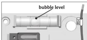
Figure 7.

Figure 8.
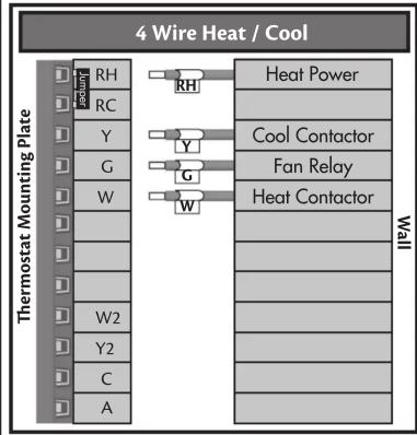
- Check the charts on the back of this sheet and identify your system type. They are divided by Conventional and Heat Pump installations.
- Raise all of the levers on the terminals you will be using. Heat Pump Installation labels are located on the left of the terminal blocks on the mounting plate and Conventional labels are on the right. If your installation does not call for the jumper, remove it now. It is located underneath the wire holes, between the RH and RC terminals on the conventional side. Figure 9.
- If one of the terminals you need has a tab in front of it, use your finger to break the tab away. Figure 9.
Note: Only break tabs you know you will be using. Double check your wiring configuration and make sure you are familiar with the terminals you will be using.

Figure 9.
- Insert the bare end of each wire all the way into the appropriate hole in the terminal block that matches the wire label then lower the lever. This will lock each of the wires in place. Tuck excess wire back into wall after they have been locked in the mounting plate.
Note: Do not insert the wires into the holes in the top of the mounting block. The wires should be inserted into the front close to the hole in the mounting plate. See Figure 8. - Before mounting the thermostat onto the mounting plate, turn it over and find the 2 switches located on the circuit board next to the battery compartment.
- Set the system switch to "Conv" if you have a conventional HVAC system or "HP" if you have a heat pump system. Set the furnace type to "Elc" if you have an electric convention system or a heat pump. "Gas/Oil" will be used if you have gas or oil based conventional system. Figure 10.
Note: Conventional systems use the compressor for air conditioning and a separate furnace for heat. Heat pump systems use the compressor for both heating and cooling.
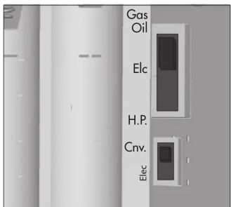
Figure 10.
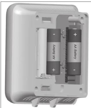
- Lay the ribbon across the battery compartment and install 2 (AA) Batteries into the back of the thermostat over it, Figure 10., and snap the thermostat on to the mounting plate. Refer to "Setup" on page 10 of your owner's manual to continue setup, scheduling, and daily use.
natural_image
Interior view of an open battery pack with two batteries and a spring, showing internal structure (no text or symbols visible)Figure 11.
Technical Support
If you have any additional questions or problems with your Hunter thermostat, please call:
USA: 1-888-830-1326
Canada: 1-866-268-1936
Hours of operation are from 7:00 am to 7:00 pm Monday - Friday and 8:00 am to 5:00 pm on Saturday, Central Time. You may also contact us over the Internet at www.hunterfan.com.
Figure 4.
| Hunter Carrier Coleman Comfortmaker Bryant, Payne Rheem Ruud | Trane,Weathertron | York Lennox (1) Lennox (2) | |||||||
| RRRRRRRRR V-VR | |||||||||
| Y Y or Y1 Y Y Y Y Y Y M | |||||||||
| E | W2 | W2 | W1 | W2 | W2 | W | W | W1 | Y |
| E | E | Jumper to W2 | E | E | X2 | Jumper to W2 | E | E | |
| O O | O O | O O | O R | ||||||
| B | B | B | |||||||
| G | G | G | G | G | G | G | G | G | F |
| L | L or F | L | L or X | L | L | X | L | ||
| C C X | C, X, X1 G, X, X1 | X B B C X | |||||||
CoNveNTioNaI


flowchart
graph TD
    A["Single Stage Heat Pump"] --> B["Thermostat Mounting Plate"]
    B --> C["Compressor Contact"]
    B --> D["Fan Relay"]
    B --> E["Cool Relay / Valve"]
    B --> F["Heat 24V Supply"]
    B --> G["R"]
    B --> H["Y"]
    B --> I["G"]
    B --> J["L"]
    B --> K["O"]
    B --> L["B"]
    B --> M["Aux/E"]
    B --> N["Y2"]
    B --> O["C"]


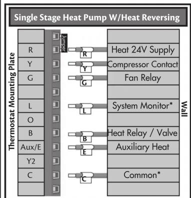


flowchart
graph TD
    A["Multi-Stage Heat Pump"] --> B["Thermostat Mounting Plate"]
    B --> C["Wall Mounting"]
    C --> D["Heat 24V Supply"]
    C --> E["Compressor Contact"]
    C --> F["Fan Relay"]
    C --> G["System Monitor*"]
    C --> H["Cool Relay / Valve"]
    C --> I["Auxiliary Heat"]
    C --> J["Second-Stage Cool"]
    C --> K["Common*"]
* The common wire "C" and system monitor wire "L" may or may not be present.


Brand : HUNTER
Model : 44132
Category : Thermostat