
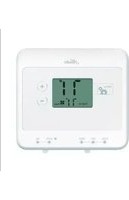
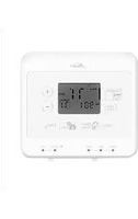
40135 - Thermostat HUNTER - Free user manual and instructions
Find the device manual for free 40135 HUNTER in PDF.


| Product Type | Thermostat |
| Brand | Hunter |
| Model | 40135 |
| Dimensions | 4.5 x 4.5 x 1.2 inches (11.4 x 11.4 x 3.0 cm) |
| Weight | 0.5 lbs (0.23 kg) |
| Power Source | 2 AA batteries (included) or 24 VAC hardwired |
| Display Type | Digital LCD |
| Temperature Range | 45°F to 90°F (7°C to 32°C) |
| Programmable | Yes, 7-day programmable with 4 periods per day |
| Fan Control | Auto and On modes |
| Compatibility | Most single-stage heating/cooling systems |
| Installation | Wall mount, requires screwdriver and level |
| Cleaning Instructions | Wipe with a soft, dry cloth. Do not use liquids or cleaners. |
| Battery Life | Approximately 1 year with normal use |
| Low Battery Indicator | Yes, icon flashes on display |
| Reset Function | Yes, via reset button or battery removal |
| Safety Ratings | UL listed, low voltage |
| Warranty | 1 year limited |
| Included Accessories | Mounting screws, wall anchors, user manual |
| Country of Origin | China |
Frequently Asked Questions - 40135 HUNTER
User questions about 40135 HUNTER
0 question about this device. Answer the ones you know or ask your own.
Ask a new question about this device
Download the instructions for your Thermostat in PDF format for free! Find your manual 40135 - HUNTER and take your electronic device back in hand. On this page are published all the documents necessary for the use of your device. 40135 by HUNTER.
USER MANUAL 40135 HUNTER
Electronic/Mechanical Thermostat
installation and operation manual
Model 40135
Our Technical Support Group is available from 8 am to 5 pm CST. They may be reached toll-free at 1-888-830-1326.
Table of Contents
Important Information .... 5
Tools 6
Uninstalling the Existing Unit 9
Installing the Thermostat 12
Installing the wall plate 14
connecting the wires 15
attaching the thermostat 17
Operation 20
Indicators & Adjustments 22
Troubleshooting 25
Wiring Diagrams 27
Electronic/Mechanical Thermostat
Model 40135
Congratulations!
Thank you for choosing a Hunter thermostat. Your new Hunter thermostat will provide years of reliable service and year-round energy savings.
Please read this manual before beginning installation and save this booklet for complete operation instructions.
IMPORTANT INFORMATION
This thermostat is designed to work on the following heating and cooling systems:
Gas – Standing Pilot Gas – Electronic Ignition Gas – Fired Boilers Gas – Millivolt Systems Oil – Fired Boilers Oil – Fired Furnace Electric Air conditioner Electric Furnace
This thermostat is not designed for heat pump systems or 110/220 V baseboard heating systems.
If you are unsure what kind of heating and cooling system you have, please contact a qualified HVAC Technician for assistance.
TOOLS
This thermostat includes two #8 slotted screws and two wall anchors for mounting.
To install your new thermostat, you will need the following supplies:
Flat-head screwdriver
Small Phillips-head screwdriver
Hammer
Electric drill and 3/16" bit
Two fresh 1.5 Volt (AA) size alkaline batteries

NOTICE! Do not disconnect the wires from the existing thermostat before reading these instructions. The wires must be labeled prior to removal to ensure proper reconnection.

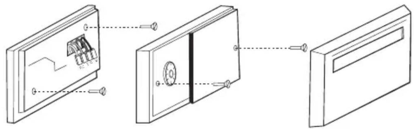
UNINSTALLING THE EXISTING UNIT
- Turn the system power OFF from the existing thermostat. Turn the power to the HVAC system OFF at the main power panel or at the furnace.
- Remove the existing thermostat cover to access the wires from the wall.
(Some thermostats may have multiple covers, screws or other locking devices that must be removed or disengaged.)
- Locate, but do not disconnect the wires.
(If wires are not visible, they may be connected to the back of the wall plate. Some models may have doors that open to expose the wires and mounting screws.)

* See pg 27 for complete wiring diagram.
UNINSTALLING THE EXISTING UNIT, CONT.
4. Using the provided stickers, label each wire according to the chart.
(If the terminals are not labeled, contact a qualified HVAC technician.)
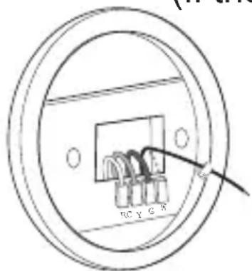
Note: Wire colors do not always comply with standards, so wire color should be ignored. Refer to the existing terminal designation for proper identification.
*If a wire marked C is present, C may be a Common wire and should not be used. If you have a wire marked C, do not connect it to any terminal. This wire is used only for non-battery powered thermostats.
- Do not let the wires slip back into the wall during disconnection. You may want to secure the wires to the wall as you disconnect them. After all wires are labeled, disconnect each wire and remove the existing wall plate.
INSTALLING THE THERMOSTAT
INSTALLING THE THERMOSTAT
- Remove the new thermostat from the back plate by pulling the two halves apart.


natural_image
Illustration of hands connecting a wall-mounted electrical outlet to a device, showing wiring and terminal labels (no text or symbols present)13
INSTALLING THE THERMOSTAT, CONT.
INSTALLING THE WALL PLATE
- Position the new wall plate on the wall and pull the labeled wires through the opening.
- If the existing holes do not match those on the Hunter wall plate, or if there are no existing holes, level the wall plate and mark the wall for two holes.
- Remove the wall plate and drill two 3/16" holes where marked.
- Tap the plastic anchors into the holes until they are flush with the wall.
- Reposition the wall plate on the wall, pulling the wires through the opening. Insert the mounting screws through the mounting holes and into the anchors. Verify that the thermostat is visually level and securely tighten both screws.
15
INSTALLING THE THERMOSTAT, CONT.
CONNECTING THE WIRES
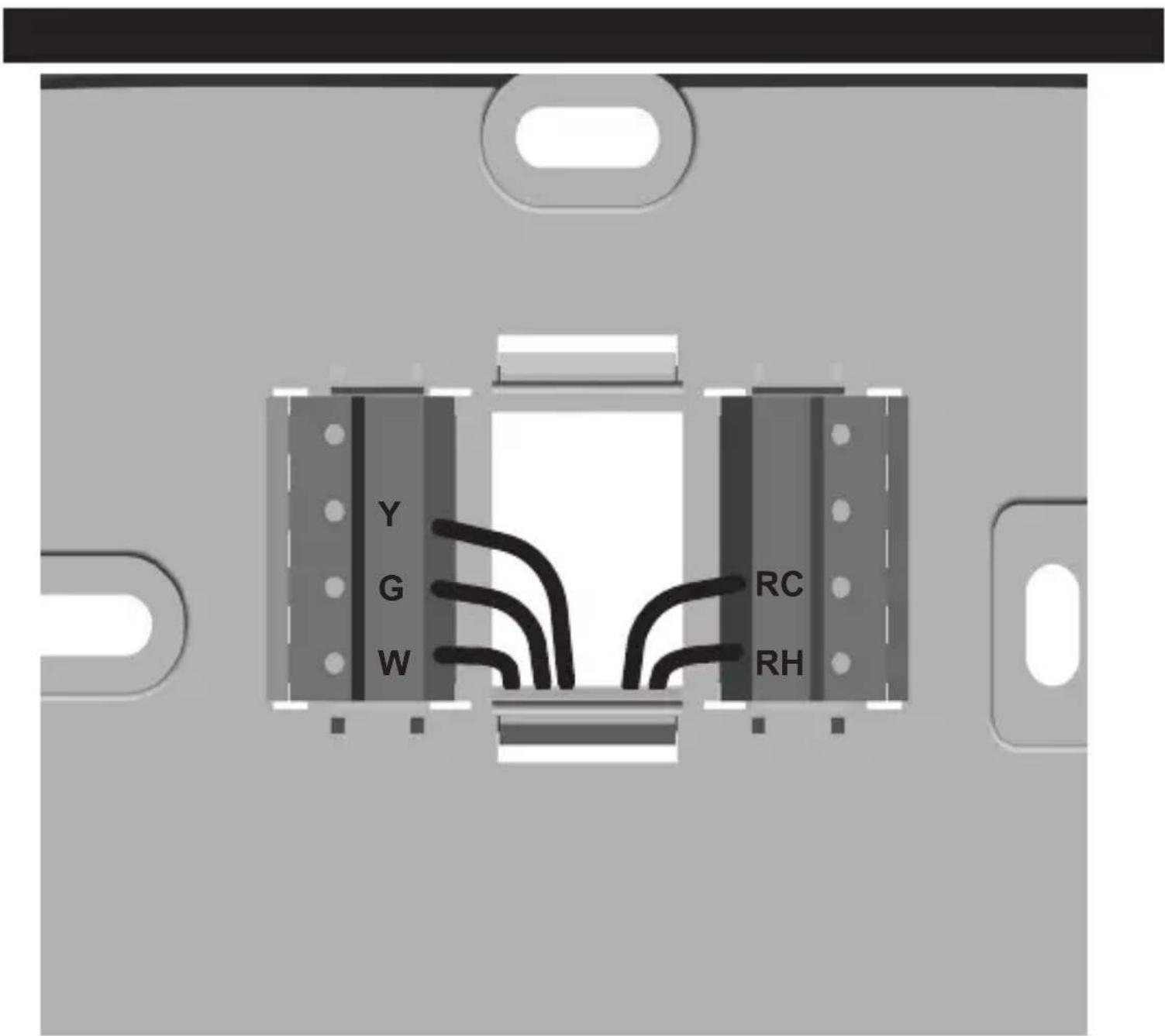
- Loosen, but do not remove, the terminal screws.
Note: A jumper wire has been provided, connecting the RC and RH terminals for systems that do not provide both an RH and RC wire. If you have both an RH and RC wire, remove this jumper. If you do not have both an RH and RC wire, leave the jumper in place.
- Match and connect the wires from the wall to the terminals as shown. Wires should be inserted behind the black terminal shields. Tighten each screw after the connection has been made.
(The ends of any extra wires should be wrapped in electrical tape and carefully pushed back into the wall.)
- Push any excess wire length back into the wall to prevent interference.
HE/HG Switch

natural_image
3D rendering of a device casing with internal components and a cable inserted (no text or symbols visible)INSTALLING THE THERMOSTAT, CONT.
ATTACHING THE THERMOSTAT
- Locate the HE/HG on the back of the thermostat. Set the switch to HG for a gas furnace or oil burner. Set the switch to HE for electric furnaces.
(The switch has no effect when the system is set to cooling mode.)
- Insert two fresh AA alkaline batteries.
- Align the thermostat with the wall plate, and snap the two halves together.
- Restore power at the electrical panel or furnace.

natural_image
3D rendering of a mechanical component with two internal slots and mounting holes, showing assembly or disassembly (no text or symbols)
OPERATION
- Set the SET TEMPERATURE SLIDER to the desired temperature.
- The SYSTEM SWITCH determines the operating mode of the thermostat. Select COOL, OFF, or HEAT
- The FAN SWITCH should normally be located in the Auto position. To run the fan continuously, slide the FAN SWITCH to the ON position.
Note: In Auto, The fan will be turned on along with normal operation of your system. In a normal gas or oil furnace, the fan will be turned on by your furnace after its warm-up delay.
INDICATORS AND ADJUSTMENT
- The THERMOMETER indicates the room temperature.
- The BATTERY INDICATOR displays two stages of battery conditions. The first warning is the WEAK BATTERY WARNING, indicated by the BATTERY INDICATOR flashing once approximately every second. When this warning appears, install two fresh AA alkaline batteries at your earliest convenience.
- The second warning is the SHUT-DOWN INDICATOR, indicated by the BATTERY INDICATOR flashing approximately twice every second. When this warning appears, the thermostat is shut down and will turn your system OFF. Your system will remain shut-off until you install two fresh AA alkaline batteries.
Span Adjust
SPAN

natural_image
Close-up of a mechanical component with circular features and a hanging string (no visible text or symbols)23
INDICATORS AND ADJUSTMENTS, CONT.
Your thermostat is preset to cycle your system off and on at 1°F above and below the Set Temperature. For maximum system efficiency and a sustained comfortable temperature your system should cycle 3 - 5 times per hour. If your system is cycling either too often or not often enough, then use a small Phillips-head screwdriver to turn the SPAN ADJUST left or right to change the cycle time.
- Remove the top cover from the thermostat.
- To make your system run LONGER, turn the SPAN ADJUST clockwise.
- To make your system run SHORTER, turn the SPAN ADJUST counter clockwise.
- Reattach the top cover to the thermostat.
Note: The Span range is 0.6^ F - 3^ F. The Span setting remains the same in both the Heat and Cool modes and can be changed regardless of what position the System Switch is in.
1. My heating or cooling will not turn on or off.
1 a. Check the HE/HG switch to ensure it is set to the correct position.
1 b. Wait. There may be as much as a 4-minute delay before the system turns on or off to protect the compressor.
1 c. Check the circuit breakers and switches to ensure there is enough power to the system.
1 d. Replace the batteries with fresh AA alkaline batteries.
1 e. If applicable, make sure the furnace blower door is closed properly.
1 f. If your system has 4 wires, ensure the jumper wire is installed between the RC and RH terminals.
2. My system continues to operate when the thermostat is in the off position.
2 a. Replace unit.
TROUBLESHOOTING
Is there help on the web?
Yes. Visit http://www.hunterfan.com for more information.
Can't I just call someone?
Sure. Our Technical Support Group is available from 8 am to 5 pm CST. They may be reached toll-free at1-888-830-1326.
4-w ire Heat/CoolSystem

flowchart
graph TD
    G["Gate"] --> FanRelay["Fan Relay"]
    Rh["Rh"] --> HeatCool["Heat/Cool 24 V Supply"]
    Y["Y"] --> CoolContactor["Cool Contactor"]
    W["W"] --> HeatRelayOrValve["HeatRelay or Valve"]
5-wireeAlt/Col System

flowchart
graph TD
    G["Gate G"] --> FanRelay["Fan Relay"]
    Rc["Rc"] --> CoolSupply["Cool 24V Supply"]
    Rh["Rh"] --> HeatSupply["Heat 24V Supply"]
    Y["Y"] --> CoolContactor["Cool Contactor"]
    W["W"] --> HeatRegal["Heat Regal or Valve"]
    CoolSupply --> HeatSupply
    HeatSupply --> CoolContactor
    CoolContactor --> HeatRegal
    HeatRegal --> Ground["Ground"]
    style G fill:#fff,stroke:#000
    style Rc fill:#fff,stroke:#000
    style Rh fill:#fff,stroke:#000
    style Y fill:#fff,stroke:#000
    style W fill:#fff,stroke:#000
    style CoolSupply fill:#fff,stroke:#000
    style CoolContactor fill:#fff,stroke:#000
    style HeatRegal fill:#fff,stroke:#000
WIRING DIAGRAMS
2-w ire Heat Only System

flowchart
graph TD
    A["Heats 24V or MillivoltSupply"] --> B["Rh"]
    C["Heats Relay or Valve"] --> D["W"]
    B --> E["Ground"]
    D --> E
3-w ire Heat Only System

flowchart
graph TD
    G["Gate G"] --> FanRelay["Fan Relay"]
    Rh["Rh"] --> HeatSupply["Heat 24V Supply"]
    W["W"] --> HeatRelayOralve["Heat Relay or V alve"]
    FanRelay --> HeatSupply
    HeatSupply --> HeatRelayOralve
WIRING DIAGRAMS, CONT.
3-w ire Cool0 nly System

flowchart
graph TD
    G["Gate G"] --> FanRelay["Fan Relay"]
    Rc["Carrier Rc"] --> CoolSupply["Cool 24 V Supply"]
    Y["Y"] --> CoolContacter["Cool Contacter"]

30 © 2007 Hunter Fan Company


- Electronic/Mechanical Thermostat
- Table of Contents
- Model 40135
- IMPORTANT INFORMATION
- TOOLS
- UNINSTALLING THE EXISTING UNIT
- UNINSTALLING THE EXISTING UNIT, CONT.
- Using the provided stickers, label each wire according to the chart.
- INSTALLING THE THERMOSTAT
- INSTALLING THE THERMOSTAT, CONT.
- INSTALLING THE WALL PLATE
- CONNECTING THE WIRES
- ATTACHING THE THERMOSTAT
- OPERATION
- INDICATORS AND ADJUSTMENT
- Span Adjust
- INDICATORS AND ADJUSTMENTS, CONT.
- My heating or cooling will not turn on or off.
- My system continues to operate when the thermostat is in the off position.
- TROUBLESHOOTING
- WIRING DIAGRAMS
- WIRING DIAGRAMS, CONT.
Brand : HUNTER
Model : 40135
Category : Thermostat