
EC-2D - Barcode Reader EC Line - Free user manual and instructions
Find the device manual for free EC-2D EC Line in PDF.


| Product Type | 2D Barcode Reader |
| Brand | EC Line |
| Model | EC-2D |
| Dimensions (approx.) | 17.5 x 7.0 x 10.2 cm |
| Weight (approx.) | 200 g |
| Power Supply | USB bus power (5V, 500mA) or external power adapter (optional) |
| Interface | USB (HID, virtual COM) or RS-232 (optional) |
| Scan Capability | 1D and 2D barcodes (QR, Data Matrix, PDF417, etc.) |
| Scan Engine | CMOS image sensor, 640 x 480 pixels |
| Depth of Field | Up to 25 cm for 13 mil barcode |
| Scan Angle | Horizontal 40°, Vertical 30° |
| Decode Speed | Up to 300 scans/second |
| Indicators | LED (red/green), beeper |
| Operating Temperature | 0°C to 40°C |
| Storage Temperature | -20°C to 60°C |
| Humidity | 5% to 95% non-condensing |
| Drop Resistance | 1.5 m onto concrete |
| IP Rating | IP42 |
| Cable Length | 2 m (USB cable) |
| Material | ABS plastic |
| Cleaning | Wipe with a soft, dry cloth; avoid solvents |
| Safety Compliance | CE, FCC, RoHS |
| Spare Parts | Replacement cables, stands, mounting brackets (sold separately) |
| Repairability | Limited user-serviceable parts; refer to manual for repair centers |
| Manual Availability | Free PDF download (192 pages, English) |
Frequently Asked Questions - EC-2D EC Line
User questions about EC-2D EC Line
0 question about this device. Answer the ones you know or ask your own.
Ask a new question about this device
Download the instructions for your Barcode Reader in PDF format for free! Find your manual EC-2D - EC Line and take your electronic device back in hand. On this page are published all the documents necessary for the use of your device. EC-2D by EC Line.
USER MANUAL EC-2D EC Line
2D Area Imager Bar Code Scanner
CONFIGURATION GUIDE
For EC IG-2D, EC IG-2DBT, EC 7110-2D models



natural_image
Woman browsing clothing items in a retail store, surrounded by racks and green bags (no visible text or signage)This manual is copyrighted, with all right reserved. Under the copyright laws, this manual may not, in whole or in part, be copied, photocopied, reproduced, translated or converted to any electronic medium or machine readable form without prior written consent of maker.
Note: Due to product improvement programs, specifications and features are subject to change without prior notice.
Table of Contents
Chapter 1 General Description....1
Chapter 2 Introduction ...... 2
Chapter 3 User Preferences ....4
RETURN TO DEFAULT 4
PARAMETER SCANNING....5
BEEPER TONE 6
BEEPER VOLUME....7
BEEPER DURATION....7
TRIGGER MODES 8
POWER MODE....9
TIME DELAY TO LOW POWER MODE 10
DECODE SESSION TIMEOUT 11
BEEP AFTER GOOD DECODE....12
Chapter 4 Imager Preferences....13
SNAPSHOT MODE 15
DECODING AUTO EXPOSURE 16
DECODING ILLUMINATION .... 16
DECODE AIMING PATTERN....17
IMAGE CAPTURE AUTO EXPOSURE....17
IMAGE CAPTURE ILLUMINATION....18
EXPOSURE TIME 19
SNAPSHOT MODE TIMEOUT 20
SNAPSHOT AIMING PATTERN 20
IMAGE CROPPING....21
CROP TO PIXEL ADDRESSES....22
IMAGE RESOLUTION 23
JPEG IMAGE OPTIONS....24
JPEG QUALITY AND SIZE VALUE....24
IMAGE FILE FORMAT SELECTOR 25
BITS PER PIXEL 25
VIDEO VIEW FINDER 26
TARGET VIDEO FRAME SIZE 26
VIDEO VIEW FINDER IMAGE SIZE 26
Chapter 5 Serial Interface ...... 27
SERIAL PARAMETER DEFAULTS 28
SERIAL HOST TYPES 29
BAUD RATE 30
PARITY 31
STOP BIT SELECT 32
DATA BITS 32
CHECK RECEIVE ERRORS 33
HARDWARE HANDSHAKING 34
SOFTWARE HANDSHAKING 36
HOST SERIAL RESPONSE TIME-OUT 38
RTS LINE STATE 39
BEEP ON
INTERCHARACTER DELAY 40
IGNORE UNKNOWN CHARACTERS....41
ASCII CHARACTER SET FOR SERIAL HOSTS 42
Chapter 6 USB Interface....47
USB HOST PARAMETERS 48
NATIVE API (SNAPI) STATUS HANDSHAKING .... 50
USB COUNTRY KEYBOARD TYPES (COUNTRY CODES) ...... 50
USB KEYSTROKE DELAY 52
USB CAPS LOCK OVERRIDE....52
USB IGNORE UNKNOWN CHARACTERS 53
EMULATE KEYPAD....53
USB KEYBOARD FN 1 SUBSTITUTION....54
FUNCTION KEY MAPPING....54
SIMULATED CAPS LOCK 55
CONVERT CASE 55
ASCII CHARACTER SET FOR USB 56
Chapter 7 Symbologies ...... 67
SYMBOLOGY PARAMETER DEFAULTS....68
UPC/EAN 73
CODE 128....85
CODE 39....87
CODE 93....95
CODE 11....97
INTERLEAVED 2 OF 5 (ITF)....100
DISCRETE 2 OF 5 (DTF)....104
CODABAR (NW - 7)....106
MSI....109
POSTAL CODES....113
GS1 DATABAR....117
COMPOSITE....122
2D SYMBOLOGIES 127
PDF417 127
MICROPDF417 127
DATA MATRIX....129
MAXICODE....129
QR CODE 130
Chapter 8 Miscellaneous Scanner Options .... 138
TRANSMIT CODE ID CHARACTER....140
PREFIX/SUFFIX VALUES 141
SCAN DATA TRANSMISSION FORMAT 142
FN1 SUBSTITUTION VALUES 143
TRANSMIT "NO READ" MESSAGE 144
Chapter 9 Bluetooth Configuration .... 145
SCANNER MODE SELECTION....145
OUT OF RANGE....147
SLEEP MODE 147
BATCH MODE 148
Thank you for purchasing this barcode scanner with an advanced and versatile decoder. The decoder works with variety of barcode types, reading devices, and computer interfaces. It discriminates over twenty different symbologies automatically.
This menu provides an easy way to configure the decoding options and interface selections by scanning bar codes listed in the menu.
FCC Approval

This device had been tested in accordance with the procedures and in compliance with Part 15 Subpart B of FCC Rules. And keeps all requirements according ANSI C63.4 & FCC Part 15 B Regulation and CISPR22 Class B.
CE Standards

The CE mark as shown here indicates this product had been tested in accordance with the procedures given in European Council Directive 2004/108/EC and confirmed to comply with the Europe Standard EN55022:2006:Class B, EN 55024:1998+A1:2001+A2:2003,IEC61000-3-2:2006,IEC61000-3-3:1995+A1:2005,IEC61000-4-2:2001,IEC61000-4-2:2006,IEC61000-4-4:2004,IEC61000-4-5:2006,IEC61000-4-6:2001,IEC61000-4-8:2001,IEC61000-4-11:2004.
LEGISLATION AND WEEE SYMBOL
This marking shown on the product or its literature, indicates that it should not be disposed with other households wastes at the end of its working life. To prevent possible harm to the environment or human healthy from uncontrolled waste disposal, please separate this from other types of wastes and recycle it responsibly to promote the sustainable re-use of material resources.
Household users should contact either the retailer where they purchased this product, or their local government office, for details of wher and how they can take this item fore environm entally safe recycling. Business users should contact their supplier and check the terms and conditions of the purchase.
This document provide an easy way to program the decoding options and interface selections by scanning bar codes listed in this guide.
Important Notice
- This document is in A5 size. Please check your printing setting before printing it out.
- When printing barcodes for programming, the use of a high-resolution laser printer is strongly suggested for the best scan result.
- The settings shall be updated periodically without prior notice. For the latest version, please contact your authorized distributor.
Factory Default Setting
The factory default settings are shown with < > and bold in the following sections. You can make your own settings by scan a series of selected barcode patches in this manual to affect setup and programming of your handheld 2D Image Reader.
By scanning “Set All Defaults” Label, the settings will go back to the factory default settings.
Settings and Programming
Scan a series of selected barcode patches in this manual to affect setup and programming of your handheld 2D Image Reader. Decoding options and interface protocols can be tailored to a specific application.
Setup parameters are stored in non-volatile memory in the scanner and are retained even when power is off. Setup parameters change only when you reset them.
You may need to hide adjacent code patches with your hand when doing programming scanning.
Default Factory Device Settings
| User Preferences | ||
| Parameter | Default | |
| Set Default Parameter | All Defaults | |
| Parameter Scanning | Enable | |
| Beeper Tone | Medium | |
| Beeper Volume | High | |
| Beeper Duration | Long | |
| Trigger Mode | Handheld/Hands-free Scanner | Level |
| Scan Module | Presentation | |
| Power Mode | Handheld/Hands-free Scanner | Low Power |
| Scan Module | Low Power | |
| Time Delay to Low Power Mode | 1.0 Sec | |
| Decode Session Timeout | 9.9 Sec | |
| Timeout Between Decodes, Same Symbol | 0.4 Sec | |
| Beep After Good Decode | Enable | |
| Presentation Mode Session Timeout | 2 Seconds | |
RETURN TO DEFAULT
- For Desktop and Fixed mount default : (EC 7110-2D)
You can scan this programming code to restore the scanner's parameters to factory default configuration.
Remark: these default setting are associated to configuration in Chapter 3 to Chapter 8.
- For Handheld models default : (EC IG-2D, EC IG-2DBT)
You can scan this programming code to restore the scanner's parameters to factory default configuration.
Remark: these default setting are associated to configuration in Chapter 3 to Chapter 8.

3. For Bluetooth's default: (EC IG-2DBT)
You can scan this programming code to restore the Bluetooth's parameters to factory default configuration.
Remark: this default setting is associated to configuration in Chapter 9, no effect for wired models.
Restore the Bluetooth to Factory Default

PARAMETER SCANNING
To disable decoding of parameter bar codes, including the Set All Defaults parameter bar code, scan the Disable Parameter Scanning bar code below. To enable decoding of parameter bar codes, scan Enable Parameter Scanning.
< Enable Parameter Scanning >
Disable Parameter Scanning
BEEPER TONE
To select a decode beep frequency (tone); scan the Low Frequency, Medium Frequency, or High Frequency bar code.

Low Frequency

Medium Frequency
< High Frequency >
BEEPER VOLUME
To select a beeper volume, scan the Low Volume, Medium Volume, or High Volume bar code.
Low Volume
Medium Volume

< High Volume >
BEEPER DURATION
To select the duration for the beeper, scan one of the following bar codes.

Short

Medium

< Long >
TRIGGER MODES
- Level Mode - A trigger event activates decode processing, which continues until the trigger event ends, a valid decode, or the decode session time-out is reached. This scan mode is not available for scan module.
- Presentation Mode - When the device detects an object in its field of view it triggers and attempts to decode. The range of object detection does not vary under normal lighting conditions. This applies to decode mode only. In this mode the unit does not enter its sleep state.
- Host Mode- A host command issues the triggering signal. The device interprets a trigger pull as a level triggering option. This scan mode is not available for scan module.

(Default for handheld scanners.)

(Default for Desktop and Fixed mount scan modules)

POWER MODE
This parameter determines whether or not power remains on after a decode attempt. In low power mode, the decoder enters into a low power consumption mode to preserve battery life after each decode attempt. In continuous power mode, power remains on after each decode attempt.
Continuous On

< Low Power Mode >
TIME DELAY TO LOW POWER MODE
This parameter sets the time the decoder remains active after decoding. The decoder wakes upon trigger pull or when the host attempts to communicate with the decoder.
Note: 1. This parameter only applies when Power Mode is set to Low Power. 2. This setting is not available for scan module since it is always in presentation mode and its power is continuous on.

< 1 Second >

5 Seconds

1 Minute
5 Minutes

15 Minutes

1 Hour
DECODE SESSION TIMEOUT
This parameter sets the maximum time decode processing continues during a scan attempt. It is programmable in 0.1 second increments from 0.5 to 9.9 seconds. The default timeout is 9.9 seconds.
To set a Decode Session Timeout, scan the bar code below. Next, scan two numeric bar codes from Appendix D, Numeric Barcodes that correspond to the desired on time. Single digit numbers must have a leading zero. For example, to set a Decode Session Timeout of 0.5 seconds, scan the bar code below, and then scan the 0 and 5 bar codes. To correct an error or change the selection, scan Cancel barcode.

Timeout Between Decodes, Same Barcode Symbol
This option is used in presentation mode to prevent multiple reads of a symbol left in the Device's field of view. The timeout begins when the symbol is removed from the field of view. It is programmable in 0.1 second increments from 0.0 to 9.9 seconds. The default interval is 0.4 seconds.
To select the timeout between decodes for the same symbol, scan the bar code below, then scan two numeric bar codes from Appendix D, Numeric Bar Codes that correspond to the desired interval, in 0.1 second increments.

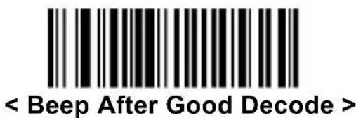
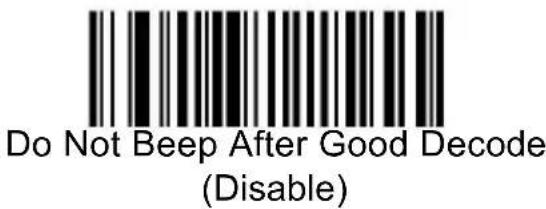
BEEP AFTER GOOD DECODE
Scan a bar code below to select whether or not the decoder issues a beep signal after a good decode. If selecting Do Not Beep after Good Decode, beeper signals are issued during parameter menu scanning and to indicate error conditions.
Lists the defaults for imaging preferences options. To change the default values, scan the appropriate bar codes in this guide.
| Imaging options | Default |
| Decoding Auto exposure | Enable |
| Decoding Illumination | Enable |
| Decode Aiming Pattern | Enable (Handheld) |
| Image Capture Auto exposure | Enable |
| Image Capture Illumination | Enable |
| Gain | 100 |
| Exposure Time | 10 ms |
| Snapshot Mode Timeout | 0 (30 seconds) |
| Snapshot Aiming Pattern | Enable |
| Image Cropping | Disable |
| Crop to Pixel Addresses | 0 top, 0 left, 479 bottom, 639 right |
| Image Resolution | Full |
| JPEG Image Options | Quality |
| JPEG Quality Value | 65 |
| JPEG Size Value | 40 (41K) |
| Image File Format Selection | JPEG |
| Bits per Pixel (BPP) | 8 BPP |
| Signature Capture | Disable |
| Signature Capture Image File Format Selection | JPEG |
| Signature Capture Bits per Pixel (BPP) | 8 BPP |
| Signature Capture Width | 400 |
| Signature Capture Height | 100 |
| Signature Capture JPEG Quality | 65 |
| Video View Finder | Disable |
| Video View Finder Image Size | 1700 bytes |
The parameters in this section control image capture characteristics. Image capture occurs in all modes of operation, including decode, video, and snapshot.
The decoder has three modes of operation:
* Decode Mode
* Snapshot Mode
Decode Mode
By default, upon a trigger event, the decoder attempts to locate and decode enabled bar codes within its field of view. The decoder remains in this mode as long as the trigger is active or until a bar code is decoded.
SNAPSHOT MODE
Use Snapshot Mode to capture a high-quality image and transmit it to the host. To temporarily enter this mode scan the Snapshot Mode bar code. While in this mode the decoder blinks the orange LED at 1-second intervals to indicate it is not in standard operating (decode) mode.
In Snapshot Mode, the decoder turns on the laser aiming pattern to highlight the area to be captured in the image. The next trigger event instructs the decoder to capture a high quality image and transmit it to the host. A short time may pass (less than 2 seconds) between when the trigger is activated and the image is captured as the decoder adjusts to the lighting conditions. Hold the decoder steady until the image is captured, denoted by a single beep.
If a trigger event is not activated within the Snapshot Mode Timeout period, the device returns to Decode Mode. Use Snapshot Mode Timeout to adjust this timeout period. The default timeout period is 30 seconds.
To disable the laser aiming pattern during Snapshot Mode, see Snapshot Aiming Pattern.
Use Video View Finder to enable Snapshot with Viewfinder Mode. In this mode the decoder behaves as a video camera until the trigger is active, at which time a Snapshot is performed as described above.

Snapshot Mode
DECODING AUTO EXPOSURE
Select Enable Auto exposure to allow the device to control gain settings and exposure (integration) time to best capture an image for the selected operation mode.
Select Disable Auto exposure to manually adjust the gain and exposure time. This option is only recommended for advanced users with difficult image capture situations.

< Enable Decoding Auto exposure >
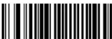
Disable Decoding Auto exposure
DECODING ILLUMINATION
Selecting Enable Illumination causes the decoder to flash illumination on every image capture to aid decoding. Select Disable Illumination to prevent the decoder from using decoding illumination.
Enabling illumination usually results in superior images. The effectiveness of the illumination decreases as the distance to the target increases.

< Enable Decoding Illumination >
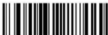
Disable Decoding Illumination
DECODE AIMING PATTERN
This parameter only applies when in Decode Mode. Select Enable Decode Aiming Pattern to project the aiming pattern during bar code capture, or Disable Decode Aiming Pattern to turn the aiming pattern off.

< Enable Decode Aiming Pattern > (Default for handheld scanners.)

(Default for desktop and fixed mount module.)
IMAGE CAPTURE AUTO EXPOSURE
Select Enable Auto exposure to allow the decoder to control gain settings and exposure (integration) time to best capture an image for the selected operation mode.
Select Disable Auto exposure to manually adjust the gain and exposure time. This option is only recommended for advanced users with difficult image capture situations.


IMAGE CAPTURE ILLUMINATION
Selecting Enable Image Capture Illumination causes the decoder to flash on every image capture. Select Disable Illumination to prevent the decoder from
using artificial illumination.
Enabling illumination usually results in superior images. The effectiveness of the illumination decreases as the distance to the target increases.
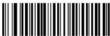
< Enable Image Capture Illumination >
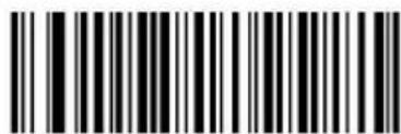
Disable Image Capture Illumination
EXPOSURE TIME
This parameter is only available when Image Capture Auto exposure is disabled. Exposure Time controls the amount of time the CCD is allowed to collect light, much like the shutter speed for a camera. Generally, the brighter the environment is, the shorter the exposure time would be. Set the manual exposure time to one of the following values: 5 ms, 10 ms, 15 ms, 20 ms, 25 ms, or 30 ms. Increasing the exposure time past 20 ms in a handheld application increases the risk of blurring the image due to hand jitter.

5 ms

<10 ms>
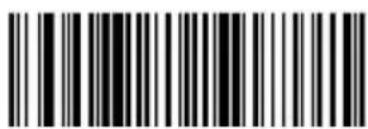
15 ms
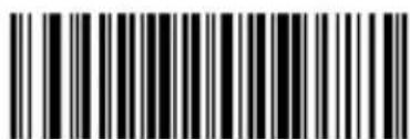
20 ms
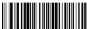
30 ms
SNAPSHOT MODE TIMEOUT
This parameter sets the amount of time the decoder remains in Snapshot Mode. The decoder exits Snapshot Mode upon a trigger event, or when the Snapshot Mode Timeout elapses. To set this timeout value, scan the bar code below followed by a bar code from Appendix D, Numeric Bar Codes. The default value is 0 which represents 30 seconds; values increment by 30. For example, 1 = 60 seconds, 2 = 90 seconds, etc.

SNAPSHOT AIMING PATTERN
Select Enable Snapshot Aiming Pattern to project the aiming pattern when in Snapshot Mode, or Disable Snapshot Aiming Pattern to turn the aiming pattern off.

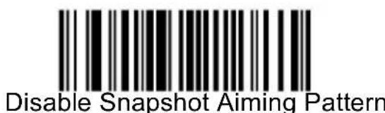
IMAGE CROPPING
This parameter crops a captured image. If Disable Image Cropping is selected, the full 640 x 480 pixels are presented. If Enable is selected, the decoder crops the image to the pixel addresses set in Crop to Pixel Addresses.
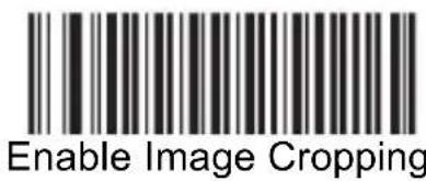
Cropping>

IMAGE RESOLUTION
This option alters image resolution before compression. Multiple pixels are combined to one pixel, resulting in a smaller image containing the original content with reduced resolution. Select one of the following values:| Resolution Value | Uncropped Image Size |
| Full | 752 x 480 |
| 1/2 | 376 x 240 |
| 1/4 | 188 x 120 |
JPEG IMAGE OPTIONS
JPEG images can be optimized for either size or for quality. Scan the Quality Selector bar code to enter a quality value; the decoder then selects the corresponding image size. Scan the Size Selector bar code to enter a size value; the decoder then selects the best image quality.  JPEG QUALITY AND SIZE VALUE
If JPEG Quality Selector is selected, scan the JPEG Quality Value bar code followed by 3 bar codes from Appendix D, Numeric Bar Codes corresponding to a value from 5 to 100, where 100 represents the highest quality image. If JPEG Size Selector is selected, scan JPEG Size Value followed by 3 bar codes from Appendix D, Numeric Bar Codes corresponding to a value from 5 to 150 which represent the file size in multiples of 1024 bytes (1K). For example, setting this value to 8 (008) permits the file size to be as large as 8192 bytes.  JPEG Quality Value (Default: 065) (5 - 100 Decimal)  JPEG Size Value (Default: 160) (5 - 350 Decimal)IMAGE FILE FORMAT SELECTOR
Select an image format appropriate for the system (BMP, TIFF, or JPEG). The decoder stores captured images in the selected format.  BMP File Format  < JPEG File Format >  TIFF File FormatBITS PER PIXEL
Select the number of significant bits per pixel (BPP) to use when capturing an image. Select 1BPP for a black and white image, 4BPP to assign 1 of 16 levels of grey to each pixel, or 8BPP to assign 1 of 256 levels of grey to each pixel. The decoder ignores these settings for JPEG files, which always use 8BPP.  1 BPP  4 BPP  < 8 BPP >VIDEO VIEW FINDER
Select Enable Video View Finder to project the video view finder while in Image Mode, or Disable Video View Finder to turn the video view finder off.  TARGET VIDEO FRAME SIZE
Select the number of 100-byte blocks to be transmitted per second. Selecting a smaller value allows more frames to be transmitted per second but reduces video quality; selecting a larger value increases video quality but slows transmission. To set the Target Video Frame Size, scan the bar code below followed by two bar codes from Appendix D, Numeric Bar Codes corresponding to the 100-byte value from 800 to 3300 bytes. For example, to select 1500 bytes, enter 1, 5. To select 900 bytes, enter 0, 9.  Target Video Frame SizeVIDEO VIEW FINDER IMAGE SIZE
Select the number of 100-byte blocks. Values range from 800 to 3000 bytes. Selecting a smaller value allows more frames to be transmitted per second; selecting a larger value increases video quality. To set the Video View Finder Imager Size, scan the bar code below followed by two bar codes from Appendix D, Numeric Bar Codes corresponding to the 100-byte value from 800 to 3000 bytes. For example, to select 1500 bytes, enter 1, 5. To select 900 bytes, enter 0, 9. Introduction
This chapter describes how to set up the decoder with a serial host. The serial interface is used to connect the decoder to point-of-sale devices, host computers, or other devices with an available serial port (e.g. com port). Note: The decoder uses TTL signal levels, which interface with most system architectures. System architectures that use RS-232C signal levels require a conversion circuitry. The serial host type requires proper configuration of the sysconfig lines, and typically require scanning bar code menus as part of initial configuration. Most computer monitors allow scanning the bar codes directly on the screen. When scanning from the screen is sure to set the document magnification to a level where the bar code can be seen clearly, and bars and/or spaces are not merging.SERIAL PARAMETER DEFAULTS
The table below lists the defaults for serial host parameters. To change any option, scan the appropriate bar code(s) provided in the Serial Host Parameters section. Note: See Appendix A, Standard Default Parameters for all user preferences, hosts, symbologies, and miscellaneous default parameters. Serial Host Default Table| Serial Host Parameters | |
| Parameter | Default |
| Serial Host Types | Standard |
| Baud Rate | 9600 |
| Parity Type | None |
| Stop Bit Select | 1 Stop Bit |
| Data Bits | 8-Bit |
| Check Receive Errors | Enable |
| Hardware Handshaking | None |
| Software Handshaking | None |
| Host Serial Response Time-out | 2 Sec |
| RTS Line State | Low RTS |
| Beep on | Disable |
| Intercharacter Delay | 0 msec |
| Nixdorf Beep/LED Options | Normal Operation |
| Ignore Unknown Characters | Send Bar Code |
SERIAL HOST TYPES
To select a serial host interface, scan one of the following bar codes.  Enable Serial Host (Standard RS232) \*Scanning Enable Serial Host (No Variant) activates the serial driver, but does not change port settings (e.g., parity, data bits, handshaking). Selecting another serial host type bar code changes these settings.  OPOS/JPOSBAUD RATE
Baud rate is the number of bits of data transmitted per second. Set the decoder's baud rate to match the baud rate setting of the host device. Otherwise, data may not reach the host device or may reach it in distorted form.    PARITY
A parity check bit is the most significant bit of each ASCII coded character. Select the parity type according to host device requirements. Select Odd parity and the parity bit value is set to 0 or 1, based on data, to ensure that an odd number of 1 bits are contained in the coded character. Select Even parity and the parity bit value is set to 0 or 1, based on data, to ensure that an even number of 1 bits are contained in the coded character. Select None when no parity bit is required.   STOP BIT SELECT
The stop bit(s) at the end of each transmitted character marks the end of transmission of one character and prepares the receiving device for the next character in the serial data stream. The number of stop bits selected (one or two) depends on the number the receiving terminal is programmed to accommodate. Set the number of stop bits to match host device requirements.  DATA BITS
This parameter allows the decoder to interface with devices requiring a 7-bit or 8-bit ASCII protocol.  CHECK RECEIVE ERRORS
Select whether or not the parity, framing, and overrun of received characters are checked. The parity value of received characters is verified against the parity parameter selected above.  < Check For Received Errors >  Do Not Check For Received Errors The data interface consists of a serial port designed to operate either with or without the hardware handshaking lines, Request to Send (RTS), and Clear to Send (CTS). If Standard RTS/CTS handshaking is not selected, scan data is transmitted as it becomes available. If Standard RTS/CTS handshaking is selected, scan data is transmitted according to the following sequence: - The decoder reads the CTS line for activity. If CTS is asserted, the decoder waits up to Host Serial Response Time-out for the host to de-assert the CTS line. If, after Host Serial Response Time-out (default), the CTS line is still asserted, the decoder sounds a transmit error, and any scanned data is lost. - When the CTS line is de-asserted, the decoder asserts the RTS line and waits up to Host Serial Response Time-out for the host to assert CTS. When the host asserts CTS, data is transmitted. If, after Host Serial Response Time-out (default), the CTS line is not asserted, the decoder sounds a transmit error, and discards the data. - When data transmission is complete, the decoder de-asserts RTS 10 msec after sending the last character. - The host should respond by negating CTS. The decoder checks for a de-asserted CTS upon the next transmission of data. During the transmission of data, the CTS line should be asserted. If CTS is deasserted for more than 50 ms between characters, the transmission is aborted, the decoder sounds a transmission error, and the data is discarded. If the above communication sequence fails, the decoder issues an error indication. In this case, the data is lost and must be rescanned. If Hardware Handshaking and Software Handshaking are both enabled, Hardware Handshaking takes precedence. Note: The DTR signal is jumpered to the active state. - None: Scan the bar code below if no Hardware Handshaking is desired. - Standard RTS/CTS: Scan the bar code below to select Standard RTS/CTS Hardware Handshaking. - RTS/CTS Option 1: When RTS/CTS Option 1 is selected, the decoder asserts RTS before transmitting and ignores the state of CTS. The decoder de-asserts RTS when the transmission is complete. - RTS/CTS Option 2: When Option 2 is selected, RTS is always high or low (user-programmed logic level). However, the decoder waits for CTS to be asserted before transmitting data. If CTS is not asserted within Host Serial Response Time-out (default), the • RTS/CTS Option 3: When Option 3 is selected, the decoder asserts RTS prior to any data transmission, regardless of the state of CTS. The decoder waits up to Host Serial Response Time-out (default) for CTS to be asserted. If CTS is not asserted during this time, the decoder issues an error indication and discards the data. The decoder de-asserts RTS when transmission is complete.     SOFTWARE HANDSHAKING
This parameter offers control of the data transmission process in addition to, or instead of, that offered by hardware handshaking. There are five options. If Software Handshaking and Hardware Handshaking are both enabled, Hardware Handshaking takes precedence. - None: When this option is selected, data is transmitted immediately. No response is expected from host. - ACK/NAK: When this option is selected, after transmitting data, the decoder expects either an ACK or NAK response from the host. When a NAK is received, the decoder transmits the same data again and waits for either an ACK or NAK. After three unsuccessful attempts to send data when NAKs are received, the decoder issues an error indication and discards the data. - The decoder waits up to the programmable Host Serial Response Time-out to receive an ACK or NAK. If the decoder does not get a response in this time, it issues an error indication and discards the data. There are no retries when a time-out occurs. - ENQ: When this option is selected, the decoder waits for an ENQ character from the host before transmitting data. If an ENQ is not received within the Host Serial Response Time-out, the decoder issues an error indication and discards the data. The host must transmit an ENQ character at least every Host Serial Response Time-out to prevent transmission errors. - ACK/NAK with ENQ: This combines the two previous options. For re-transmissions of data, due to a NAK from the host, an additional ENQ is not required. • XON/XOFF: An XOFF character turns the decoder transmission off until the decoder receives an XON character. There are two situations for XON/XOFF: - XOFF is received before the decoder has data to send. When the decoder has data to send, it waits up to Host Serial Response Time-out for an XON character before transmission. If the XON is not received within this time, the decoder issues an error indication and discards the data. - XOFF is received during a transmission. Data transmission then stops after sending the current byte. When the decoder receives an XON character, it sends the rest of the data message. The decoder waits indefinitely for the XON.     HOST SERIAL RESPONSE TIME-OUT
This parameter specifies how long the decoder waits for an ACK, NAK, or CTS before determining that a transmission error has occurred. This only applies when in one of the ACK/NAK Software Handshaking modes, or RTS/CTS Hardware Handshaking option.     RTS LINE STATE
This parameter sets the idle state of the Serial Host RTS line. Scan a bar code below to select Low RTS or High RTS line state.  < Host: Low RTS >  Host: High RTSBEEP ON
When this parameter is enabled, the decoder issues a beep when a INTERCHARACTER DELAY
This parameter specifies the intercharacter delay inserted between character transmissions.  < Minimum: 0 msec >  Low: 25 msec  Medium: 50 msec  High: 75 msec  Maximum: 99 msecIGNORE UNKNOWN CHARACTERS
Unknown characters are characters the host does not recognize. When Send Bar Codes with Unknown Characters is selected, all bar code data is sent except for unknown characters, and no error beeps sound on the decoder. When Do Not Send Bar Codes With Unknown Characters is selected, bar code data is sent up to the first unknown character and then an error beep will sound on the decoder.  ASCII CHARACTER SET FOR SERIAL HOSTS
The values in the table below can be assigned as prefixes or suffixes for ASCII character data transmission. Prefix/Suffix Values| Prefix/Suffix Value | Full ASCII Code 39 Encode Character | ASCII Character |
| 1000 | %U | NUL |
| 1001 | A | SOH |
| 1002 | B | STX |
| 1003 | C | ETX |
| 1004 | D | EOT |
| 1005 | E | ENQ |
| 1006 | F | ACK |
| 1007 | G | BELL |
| 1008 | H | BCKSPC |
| 1009 | I | HORIZ TAB |
| 1010 | J | LF/NW LN |
| 1011 | K | VT |
| 1012 | L | FF |
| 1013 | M | CR/ENTER |
| 1014 | N | SO |
| 1015 | O | SI |
| 1016 | P | DLE |
| 1017 | Q | DC1/XON |
| 1018 | R | DC2 |
| 1019 | S | DC3/XOFF |
| 1020 | T | DC4 |
| 1021 | U | NAK |
| 1022 | V | SYN |
| 1023 | W | ETB |
| 1024 | X | CAN |
| 1025 | Y | EM |
| 1026 | Z | SUB |
| 1027 | %A | ESC |
| 1028 | %B | FS |
| 1029 | %C | GS |
| 1030 | %D | RS |
| 1031 | %E | US |
| 1032 | Space | Space |
| 1033 | /A | ! |
| 1034 | /B | " |
| 1035 | /C | # |
| 1036 | /D | $ |
| 1037 | /E | % |
| 1038 | /F | & |
| 1039 | /G | ' |
| 1040 | /H | ( |
| 1041 | /I | ) |
| 1042 | /J | * |
| 1043 | /K | + |
| 1044 | /L | , |
| 1045 | - | - |
| 1046 | . | . |
| 1047 | /O | / |
| 1048 | 0 | 0 |
| 1049 | 1 | 1 |
| 1050 | 2 | 2 |
| 1051 | 3 | 3 |
| 1052 | 4 | 4 |
| 1053 | 5 | 5 |
| 1054 | 6 | 6 |
| 1055 | 7 | 7 |
| 1056 | 8 | 8 |
| 1057 | 9 | 9 |
| 1058 | /Z | : |
| 1059 | %F | ; |
| 1060 | %G | < |
| 1061 | %H | = |
| 1062 | %I | > |
| 1063 | %J | ? |
| 1064 | %V | @ |
| 1065 | A | A |
| 1066 | B | B |
| 1067 | C | C |
| 1068 | D | D |
| 1069 | E | E |
| 1070 | F | F |
| 1071 | G | G |
| 1072 | H | H |
| 1073 | I | I |
| 1074 | J | J |
| 1075 | K | K |
| 1076 | L | L |
| 1077 | M | M |
| 1078 | N | N |
| 1079 | O | O |
| 1080 | P | P |
| 1081 | Q | Q |
| 1082 | R | R |
| 1083 | S | S |
| 1084 | T | T |
| 1085 | U | U |
| 1086 | V | V |
| 1087 | W | W |
| 1088 | X | X |
| 1089 | Y | Y |
| 1090 | Z | Z |
| 1091 | %K | [ |
| 1092 | %L | \ |
| 1093 | %M | ] |
| 1094 | %N | ^ |
| 1095 | %O | - |
| 1096 | %W | ` |
| 1097 | +A | a |
| 1098 | +B | b |
| 1099 | +C | c |
| 1100 | +D | d |
| 1101 | +E | e |
| 1102 | +F | f |
| 1103 | +G | g |
| 1104 | +H | h |
| 1105 | +I | i |
| 1106 | +J | j |
| 1107 | +K | k |
| 1108 | +L | I |
| 1109 | +M | m |
| 1110 | +N | n |
| 1111 | +O | o |
| 1112 | +P | p |
| 1113 | +Q | q |
| 1114 | +R | r |
| 1115 | +S | s |
| 1116 | +T | t |
| 1117 | +U | u |
| 1118 | +V | v |
| 1119 | +W | w |
| 1120 | +X | x |
| 1121 | +Y | y |
| 1122 | +Z | z |
| 1123 | %P | { |
| 1124 | %Q | | |
| 1125 | %R | } |
| 1126 | %S | ~ |
| 1127 | Undefined | |
| 7013 | ENTER |
Introduction
This chapter describes how to set up the decoder with a USB host. The decoder connects directly to a USB host, or a powered USB hub, and is powered by it. No additional power supply is required. Note: Most computer monitors allow scanning the bar codes directly on the screen. When scanning from the screen, be sure to set the document magnification to a level where the bar code can be seen clearly, and bars and/or spaces are not merging.USB Parameter Defaults
Table below lists the defaults for USB host parameters. To change any option, scan the appropriate barcode(s) provided in the Parameter Descriptions section. Note: See Appendix A, Standard Default Parameters for all user preferences, hosts, symbologies, and miscellaneous default parameters. USB Host Default Table| USB Host Parameters | |
| Parameters | Default |
| USB Device Type | HID Keyboard Emulation |
| Symbol Native API (SNAPI) Status Handshaking | Enable SNAPI Status Handshaking |
| USB Country Keyboard Types (Country Codes) | North American |
| USB Keystroke Delay | No Delay |
| USB CAPS Lock Override | Disable |
| USB Ignore Unknown Characters | Enable |
| Emulate Keypad | Disable |
| USB FN1 Substitution | Disable |
| Function Key Mapping | Disable |
| Simulated Caps Lock | Disable |
| Convert Case | No Case Conversion |
USB HOST PARAMETERS
USB Device Type
Select the desired USB device type. Note: When changing USB Device Types, the decoder automatically resets. The decoder issues the standard startup beep sequences.      \* Note: Steps for activating CDC COM port emulation (USB virtual COM): 1. Execute the driver (installMOTCDC.exe). If you don't have the driver, contact your distributor. 2. Connect the scanner USB cable to the host computer. The scanner would give a "Do Re Mi" melody when powered on. 3. Read the "CDC COM Port Emulation" barcode to set up the interface. 4. On the computer, check Device Manager to see if the computer successfully detects the scanner as "Bar Code Scanner." The COM port number would vary depending on different hardware environment. 5. If you can't directly install the driver follow the Found New Hardware Wizard to locate the install the driver. NATIVE API (SNAPI) STATUS HANDSHAKING
After selecting a SNAPI interface as the USB device type, select whether to enable or disable status handshaking.  USB COUNTRY KEYBOARD TYPES (COUNTRY CODES)
Scan the bar code corresponding to the keyboard type. This setting applies only to the USB HID Keyboard Emulation device. Note: When changing USB country keyboard types the decoder automatically resets. The decoder issues the standard startup beep sequences.           USB KEYSTROKE DELAY
This parameter sets the delay, in milliseconds, between emulated keystrokes. Scan a bar code below to increase the delay when hosts require a slower transmission of data.   USB CAPS LOCK OVERRIDE
This option applies only to the HID Keyboard Emulation device. When enabled, the case of the data is preserved regardless of the state of the caps lock key. This setting is always enabled for the Japanese, Windows (ASCII) keyboard type and can not be disabled.  USB IGNORE UNKNOWN CHARACTERS
This option applies only to the HID Keyboard Emulation device and IBM device. Unknown characters are characters the host does not recognize. When Send Bar Codes With Unknown Characters is selected, all bar code data is sent except for unknown characters, and no error beeps sound. When Do Not Send Bar Codes With Unknown Characters is selected, for IBM devices, bar codes containing at least one unknown character are not sent to the host, and an error beep sounds. For HID Keyboard Emulation devices, the bar code characters up to the unknown character are sent, and an error beep sounds.  < Send Bar Codes with Unknown Characters (Transmit) >  Do Not Send Bar Codes with Unknown Characters (Disable)EMULATE KEYPAD
When enabled, all characters are sent as ASCII sequences over the numeric keypad. For example ASCII A would be sent as "ALT make" 0 6 5 "ALT Break". This allows support for other country variants.  < Disable Keypad Emulation >  Enable Keypad EmulationUSB KEYBOARD FN 1 SUBSTITUTION
This option applies only to the USB HID Keyboard Emulation device. When enabled, this allows replacement of any FN 1 characters in an EAN 128 bar code with a Key Category and value chosen by the user.  Enable  < Disable >FUNCTION KEY MAPPING
ASCII values under 32 are normally sent as a control-key sequence. When this parameter is enabled, the keys in bold are sent in place of the standard key mapping. Table entries that do not have a bold entry remain the same whether or not this parameter is enabled.  < Disable Function Key Mapping >  Enable Function Key MappingSIMULATED CAPS LOCK
When enabled, the decoder inverts upper and lower case characters on the bar code as if the Caps Lock state is enabled on the keyboard. This inversion is done regardless of the current state of the keyboard's Caps Lock state.  < Disable Simulated Caps Lock >  Enable Simulated Caps LockCONVERT CASE
When enabled, the decoder converts all bar code data to the selected case.  < No Case Conversion >  Convert All to Upper Case  Convert All to Lower Case USB Prefix/Suffix Values| Prefix/ Suffix Value | Full ASCII Code 39 Encode Character | Keystroke |
| 1000 | %U | CTRL 2 |
| 1001 | A | CTRL A |
| 1002 | B | CTRL B |
| 1003 | C | CTRL C |
| 1004 | D | CTRL D |
| 1005 | E | CTRL E |
| 1006 | F | CTRL F |
| 1007 | G | CTRL G |
| 1008 | H | CTRL H/BACKSPACE ^1 |
| 1009 | I | CTRL I/HORIZONTAL TAB^{1} |
| 1010 | J | CTRL J |
| 1011 | K | CTRL K |
| 1012 | L | CTRL L |
| 1013 | M | CTRL M/ENTER^{1} |
| 1014 | N | CTRL N |
| 1015 | O | CTRL O |
| 1016 | P | CTRL P |
| 1017 | Q | CTRL Q |
| 1018 | R | CTRL R |
| 1019 | S | CTRL S |
| 1020 | T | CTRL T |
| 1021 | U | CTRL U |
| 1022 | V | CTRL V |
| 1023 | W | CTRL W |
| 1024 | X | CTRL X |
| 1025 | Y | CTRL Y |
| 1026 | Z | CTRL Z |
| 1027 | %A | CTRL [/ESC ^1 |
| 1028 | %B | CTRL \ |
| 1029 | %C | CTRL ] |
| 1030 | %D | CTRL 6 |
| 1031 | %E | CTRL |
| 1032 | Space | Space |
| 1033 | /A | ! |
| 1034 | /B | “ |
| 1035 | /C | # |
| 1036 | /D | $ |
| 1037 | /E | % |
| 1038 | /F | & |
| 1039 | /G | ‘ |
| 1040 | /H | ( |
| 1041 | /I | ) |
| 1042 | /J | * |
| 1043 | /K | + |
| 1044 | /L | , |
| 1045 | - | - |
| 1046 | . | . |
| 1047 | /O | / |
| 1048 | 0 | 0 |
| 1049 | 1 | 1 |
| 1050 | 2 | 2 |
| 1051 | 3 | 3 |
| 1052 | 4 | 4 |
| 1053 | 5 | 5 |
| 1054 | 6 | 6 |
| 1055 | 7 | 7 |
| 1056 | 8 | 8 |
| 1057 | 9 | 9 |
| 1058 | /Z | : |
| 1059 | %F | ; |
| 1060 | %G | < |
| 1061 | %H | = |
| 1062 | %I | > |
| 1063 | %J | ? |
| 1064 | %V | @ |
| 1065 | A | A |
| 1066 | B | B |
| 1067 | C | C |
| 1068 | D | D |
| 1069 | E | E |
| 1070 | F | F |
| 1071 | G | G |
| 1072 | H | H |
| 1073 | I | I |
| 1074 | J | J |
| 1075 | K | K |
| 1076 | L | L |
| 1077 | M | M |
| 1078 | N | N |
| 1079 | O | O |
| 1080 | P | P |
| 1081 | Q | Q |
| 1082 | R | R |
| 1083 | S | S |
| 1084 | T | T |
| 1085 | U | U |
| 1086 | V | V |
| 1087 | W | W |
| 1088 | X | X |
| 1089 | Y | Y |
| 1090 | Z | Z |
| 1091 | %K | [ |
| 1092 | %L | \ |
| 1093 | %M | ] |
| 1094 | %N | ^ |
| 1095 | %O | - |
| 1096 | %W | ` |
| 1097 | +A | a |
| 1098 | +B | b |
| 1099 | +C | c |
| 1100 | +D | d |
| 1101 | +E | e |
| 1102 | +F | f |
| 1103 | +G | g |
| 1104 | +H | h |
| 1105 | +I | i |
| 1106 | +J | j |
| 1107 | +K | k |
| 1108 | +L | l |
| 1109 | +M | m |
| 1110 | +N | n |
| 1111 | +O | o |
| 1112 | +P | p |
| 1113 | +Q | q |
| 1114 | +R | r |
| 1115 | +S | s |
| 1116 | +T | t |
| 1117 | +U | u |
| 1118 | +V | v |
| 1119 | +W | w |
| 1120 | +X | x |
| 1121 | +Y | y |
| 1122 | +Z | z |
| 1123 | %P | { |
| 1124 | %Q | | |
| 1125 | %R | } |
| 1126 | %S | ~ |
| The keystroke in bold is sent only if the “Function Key Mapping” is enabled. Otherwise, the unbolded keystroke is sent. | ||
| ALT Keys | Keystroke |
| 2064 | ALT 2 |
| 2065 | ALT A |
| 2066 | ALT B |
| 2067 | ALT C |
| 2068 | ALT D |
| 2069 | ALT E |
| 2070 | ALT F |
| 2071 | ALT G |
| 2072 | ALT H |
| 2073 | ALT I |
| 2074 | ALT J |
| 2075 | ALT K |
| 2076 | ALT L |
| 2077 | ALT M |
| 2078 | ALT N |
| 2079 | ALT O |
| 2080 | ALT P |
| 2081 | ALT Q |
| 2082 | ALT R |
| 2083 | ALT S |
| 2084 | ALT T |
| 2085 | ALT U |
| 2086 | ALT V |
| 2087 | ALT W |
| 2088 | ALT X |
| 2089 | ALT Y |
| 2090 | ALT Z |
| GUI Key | Keystroke |
| 3000 | Right Control Key |
| 3048 | GUI 0 |
| 3049 | GUI 1 |
| 3050 | GUI 2 |
| 3051 | GUI 3 |
| 3052 | GUI 4 |
| 3053 | GUI 5 |
| 3054 | GUI 6 |
| 3055 | GUI 7 |
| 3056 | GUI 8 |
| 3057 | GUI 9 |
| 3065 | GUI A |
| 3066 | GUI B |
| 3067 | GUI C |
| 3068 | GUI D |
| 3069 | GUI E |
| 3070 | GUI F |
| 3071 | GUI G |
| 3072 | GUI H |
| 3073 | GUI I |
| 3074 | GUI J |
| 3075 | GUI K |
| 3076 | GUI L |
| 3077 | GUI M |
| 3078 | GUI N |
| 3079 | GUI O |
| 3080 | GUI P |
| 3081 | GUI Q |
| 3082 | GUI R |
| 3083 | GUI S |
| 3084 | GUI T |
| 3085 | GUI U |
| 3086 | GUI V |
| 3087 | GUI W |
| 3088 | GUI X |
| 3089 | GUI Y |
| 3090 | GUI Z |
| Note: GUI Shift Keys - The AppleTM iMac keyboard has an apple key on either side of the space bar. Windows-based systems have a GUI key to the left of the left ALT key, and to the right of the right ALT key. | |
| F Keys | Keystroke |
| 5001 | F1 |
| 5002 | F2 |
| 5003 | F3 |
| 5004 | F4 |
| 5005 | F5 |
| 5006 | F6 |
| 5007 | F7 |
| 5008 | F8 |
| 5009 | F9 |
| 5010 | F10 |
| 5011 | F11 |
| 5012 | F12 |
| 5013 | F13 |
| 5014 | F14 |
| 5015 | F15 |
| 5016 | F16 |
| 5017 | F17 |
| 5018 | F18 |
| 5019 | F19 |
| 5020 | F20 |
| 5021 | F21 |
| 5022 | F22 |
| 5023 | F23 |
| 5024 | F24 |
| Numeric Keypad | Keystroke |
| 6042 | * |
| 6043 | + |
| 6044 | undefined |
| 6045 | - |
| 6046 | . |
| 6047 | / |
| 6048 | 0 |
| 6049 | 1 |
| 6050 | 2 |
| 6051 | 3 |
| 6052 | 4 |
| 6053 | 5 |
| 6054 | 6 |
| 6055 | 7 |
| 6056 | 8 |
| 6057 | 9 |
| 6058 | Enter |
| 6059 | Num Lock |
| Extended Keypad | Keystroke |
| 7001 | Break |
| 7002 | Delete |
| 7003 | PgUp |
| 7004 | End |
| 7005 | Pg Dn |
| 7006 | Pause |
| 7007 | Scroll Lock |
| 7008 | Backspace |
| 7009 | Tab |
| 7010 | Print Screen |
| 7011 | Insert |
| 7012 | Home |
| 7013 | Enter |
| 7014 | Escape |
| 7015 | Up Arrow |
| 7016 | Down Arrow |
| 7017 | Left Arrow |
| 7018 | Right Arrow |
Introduction
This chapter describes symbology features and provides the programming bar codes for selecting these features. The device is shipped with the settings shown in the Symbology Default Table. If the default values suit requirements, programming is not necessary. There are two ways to change a parameter value: - Scan the appropriate bar codes in this guide. These new values replace the standard default values in memory. - For SSI and USB SNAPI hosts, send a “parameter send” command from the host system. Hexadecimal parameter numbers are shown in this chapter below the parameter title, and options are shown in parenthesis beneath the accompanying bar codes. See the Simple Serial Interface (SSI) Programmer’s Guide for detailed instructions for changing parameter values using this method. Note: Most computer monitors allow scanning the bar codes directly on the screen. When scanning from the screen, be sure to set the document magnification to a level where the bar code can be seen clearly, and bars and/or spaces are not merging. To return all features to default values, scan the Set Default Parameter bar code. Throughout the programming bar code menus, default values are framed.SYMBOLOGY PARAMETER DEFAULTS
Table below lists the defaults for all symbologies parameters. To change any option, scan the appropriate barcode(s) provided in the Symbologies Parameters section. Note: See Appendix A, Standard Default Parameters for all user preferences, hosts, and miscellaneous default parameters. Symbology Default Table| Parameter | Default |
| UPC/EAN | |
| UPC-A | Enable |
| UPC-E | Enable |
| UPC-E1 | Disable |
| EAN-8/JAN 8 | Enable |
| EAN-13/JAN 13 | Enable |
| Bookland EAN | Disable |
| Decode UPC/EAN/JAN Supplementals (2 and 5 digits) | Ignore |
| UPC/EAN/JAN Supplemental Redundancy | 10 |
| Transmit UPC-A Check Digit | Enable |
| Transmit UPC-E Check Digit | Enable |
| Transmit UPC-E1 Check Digit | Enable |
| UPC-A Preamble | System Character |
| UPC-E Preamble | System Character |
| UPC-E1 Preamble | System Character |
| Convert UPC-E to A | Disable |
| Convert UPC-E1 to A | Disable |
| EAN-8/JAN-8 Extend | Disable |
| UCC Coupon Extended Code | Disable |
| Code 128 | |
| Code 128 | Enable |
| UCC/EAN-128 | Enable |
| ISBT 128 | Enable |
| Code 39 | |
| Code 39 | Enable |
| Trioptic Code 39 | Disable |
| Convert Code 39 to Code 32 (Italian Pharmacy Code) | Disable |
| Code 32 Prefix | Disable |
| Set Length(s) for Code 39 | 2 to 55 |
| Code 39 Check Digit Verification | Disable |
| Transmit Code 39 Check Digit | Disable |
| Code 39 Full ASCII Conversion | Disable |
| Buffer Code 39 | Disable |
| Code 93 | |
| Code 93 | Disable |
| Set Length(s) for Code 93 | 4 to 55 |
| Code 11 | |
| Code 11 | Disable |
| Set Lengths for Code 11 | 4 to 55 |
| Code 11 Check Digit Verification | Disable |
| Transmit Code 11 Check Digit(s) | Disable |
| Interleaved 2 of 5 (ITF) | |
| Interleaved 2 of 5 (ITF) | Enable |
| Set Lengths for I 2 of 5 | 14 |
| I 2 of 5 Check Digit Verification | Disable |
| Transmit I 2 of 5 Check Digit | Disable |
| Convert I 2 of 5 to EAN 13 | Disable |
| Discrete 2 of 5 (DTF) | |
| Discrete 2 of 5 | Disable |
| Set Length(s) for D 2 of 5 | 12 |
| Codabar (NW - 7) | |
| Codabar | Disable |
| Set Lengths for Codabar | 5 to 55 |
| CLSI Editing | Disable |
| NOTIS Editing | Disable |
| MSI | |
| MSI | Disable |
| Set Length(s) for MSI | 4 to 55 |
| MSI Check Digits | One |
| Transmit MSI Check Digit | Disable |
| MSI Check Digit Algorithm | Mod 10/Mod 10 |
| Postal Codes | |
| US Postnet | Enable |
| US Planet | Enable |
| UK Postal | Enable |
| Transmit UK Postal Check Digit | Enable |
| Japan Postal | Enable |
| Australian Postal | Enable |
| Dutch Postal | Enable |
| Transmit US Postal Check Digit | Enable |
| RSS (Reduced Space Symbology) | |
| RSS 14 | Enable |
| RSS Limited | Enable |
| RSS Expanded | Enable |
| Convert RSS to UPC/EAN | Disable |
| Composite | |
| Composite CC-C | Disable |
| Composite CC-A/B | Disable |
| Composite TLC-39 | Disable |
| UPC Composite Mode | Always Linked |
| Composite Beep Mode | Beep As Each Code Type is Decoded |
| UCC/EAN Code 128 Emulation Mode for UCC/EAN Composite Codes | Disable |
| 2D Symbologies | |
| PDF417 | Enable |
| MicroPDF417 | Disable |
| Code 128 Emulation | Disable |
| Data Matrix | Enable |
| Maxicode | Enable |
| QR Code | Enable |
| Symbology-Specific Security Levels | |
| Redundancy Level | 1 |
| Security Level | 1 |
| Inter character Gap Size | Normal |
| Report Version | |
| Macro PDF | |
| Macro PDF Transmit/Decode Mode Symbols | Pass through Mode |
| Transmit Macro PDF Control Header | Disable |
| Escape Characters | None |
| Flush Macro PDF Buffer | |
| Abort Macro PDF Entry | |
UPC/EAN
Enable/Disable UPC-A
To enable or disable UPC-A, scan the appropriate barcode below.  < Enable UPC-A >  Disable UPC-AEnable/Disable UPC-E
To enable or disable UPC-E, scan the appropriate bar code below.  < Enable UPC-E >  Disable UPC-EEnable/Disable UPC-E1
UPC-E1 is disabled by default. To enable or disable UPC-E1, scan the appropriate bar code below. Note: UPC-E1 is not a UCC (Uniform Code Council) approved symbology.  Enable/Disable EAN-8/JAN-8
To enable or disable EAN-8/JAN-8, scan the appropriate bar code below.  Enable/Disable EAN-13/JAN-13
To enable or disable EAN-13/JAN-13, scan the appropriate bar code below.  Enable/Disable Bookland EAN
To enable/disable Bookland EAN, scan the appropriate barcode below.  Decode UPC/EAN/JAN Supplementals
Supplemental are bar codes appended according to specific format conventions (e.g., UPC A+2, UPC E+2, EAN 13+2). Six options are available. • If Decode UPC/EAN/JAN Only With Supplemental is selected, UPC/EAN/JAN symbols without supplemental are not decoded. - If Ignore Supplemental is selected, and the decoder is presented with a UPC/EAN/JAN with a supplemental, the UPC/EAN/JAN is decoded and the supplemental bar code is ignored. - An Auto discriminate Option is also available. If this option is selected, choose an appropriate UPC/EAN/JAN Supplemental Redundancy value from the next page. A value of 5 or more is recommended. - Enable 378/379 Supplemental Mode to delay only EAN-13/JAN-13 bar codes starting with a '378' or '379' prefix by the supplemental search process. All other UPC/EAN/JAN bar codes are exempt from the search and are reported instantly upon decodes. - Select Enable 978 Supplemental Mode to delay only EAN-13/JAN-13 bar codes starting with a '978' prefix by the supplemental search process. All other UPC/EAN/JAN bar codes are exempt from the search and are reported instantly upon decodes. - Select Enable Smart Supplemental Mode to delay only EAN-13/JAN-13 bar codes starting with a '378', '379', or '978' prefix by the supplemental search process. All other UPC/EAN/JAN bar codes are exempt from the search and are reported instantly upon decodes. Note: To minimize the risk of invalid data transmission, select either to decode or ignore supplemental characters.  Decode UPC/EAN/JAN Only With Supplemental  < Ignore Supplemental >  Auto discriminate UPC/EAN/JAN Supplemental  Enable 378/379 Supplemental Mode  Enable 978 Supplemental Mode  Enable Smart Supplemental ModeUPC/EAN/JAN Supplemental Redundancy
With Auto discriminate UPC/EAN/JAN Supplemental selected, this option adjusts the number of times a symbol without supplemental is decoded before transmission. The range is from two to thirty times. Five or above is recommended when decoding a mix of UPC/EAN/JAN symbols with and without supplemental, and the auto discriminate option is selected. The default is set at 10. Scan the bar code below to set a decode redundancy value. Next, scan two numeric bar codes in Appendix D, Numeric Bar Codes. Single digit numbers must have a leading zero. To correct an error or change a selection, scan Cancel.  UPC/EAN/JAN Supplemental RedundancyTransmit UPC-A Check Digit
The check digit is the last character of the symbol used to verify the integrity of the data. Scan the appropriate bar code below to transmit the bar code data with or without the UPC-A check digit. It is always verified to guarantee the integrity of the data.  < Transmit UPC-A Check Digit >  Do Not Transmit UPC-A Check DigitTransmit UPC-E Check Digit
The check digit is the last character of the symbol used to verify the integrity of the data. Scan the appropriate bar code below to transmit the bar code data with or without the UPC-E check digit. It is always verified to guarantee the integrity of the data.  < Transmit UPC-E Check Digit >  Do Not Transmit UPC-E Check DigitTransmit UPC-E1 Check Digit
The check digit is the last character of the symbol used to verify the integrity of the data. Scan the appropriate bar code below to transmit the bar code data with or without the UPC-E1 check digit. It is always verified to guarantee the integrity of the data.  < Transmit UPC-E1 Check Digit >  Do Not Transmit UPC-E1 Check DigitUPC-A Preamble
Preamble characters are part of the UPC symbol, and include Country Code and System Character. There are three options for transmitting a UPC-A preamble to the host device: transmit System Character only, transmit System Character and Country Code ("0" for USA), and transmit no preamble. Select the appropriate option to match the host system.  No Preamble ()  < System Character > (UPC-E Preamble
Preamble characters are part of the UPC symbol, and include Country Code and System Character. There are three options for transmitting a UPC-E preamble to the host device: transmit System Character only, transmit System Character and Country Code (“0” for USA), and transmit no preamble. Select the appropriate option to match the host system.  No Preamble ()  < System Character > (UPC-E1 Preamble
Preamble characters are part of the UPC symbol, and include Country Code and System Character. There are three options for transmitting a UPC-E1 preamble to the host device: transmit System Character only, transmit System Character and Country Code ("0" for USA), and transmit no preamble. Select the appropriate option to match the host system.  No Preamble ()  < System Character > (Convert UPC-E to UPC-A
Enable this to convert UPC-E (zero suppressed) decoded data to UPC-A format before transmission. After conversion, the data follows UPC-A format and is affected by UPC-A programming selections (e.g., Preamble, Check Digit). When disabled, UPC-E decoded data is transmitted as UPC-E data, without conversion.  Convert UPC-E to UPC-A (Enable)  < Do Not Convert UPC-E to UPC-A > (Disable)Convert UPC-E1 to UPC-A
Enable this to convert UPC-E1 decoded data to UPC-A format before transmission. After conversion, the data follows UPC-A format and is affected by UPC-A programming selections (e.g., Preamble, Check Digit). When disabled, UPC-E1 decoded data is transmitted as UPC-E1 data, without conversion.  Convert UPC-E1 to UPC-A (Enable)  < Do Not Convert UPC-E1 to UPC-A > (Disable)EAN-8/JAN-8 Extend
When enabled, this parameter adds five leading zeros to decoded EAN-8 symbols to make them compatible in format to EAN-13 symbols. When disabled, EAN-8 symbols are transmitted as is.  Enable EAN/JAN Zero Extend  < Disable EAN/JAN Zero Extend >UCC Coupon Extended Code
When enabled, this parameter decodes UPC-A bar codes starting with digit '5', EAN-13 bar codes starting with digit '99', and UPCA/EAN-128 Coupon Codes. UPCA, EAN-13, and EAN-128 must be enabled to scan all types of Coupon Codes.  Enable UCC Coupon Extended Code  < Disable UCC Coupon Extended Code > Note: Use the Decode UPC/EAN Supplemental Redundancy parameter to control auto discrimination of the EAN128 (right half) of a coupon code.Enable/Disable Code 128
To enable or disable Code 128, scan the appropriate bar code below.  < Enable Code 128 >  Disable Code 128Enable/Disable UCC/EAN-128
To enable or disable UCC/EAN-128, scan the appropriate bar code below.  < Enable UCC/EAN-128 >  Disable UCC/EAN-128Enable/Disable ISBT 128
ISBT 128 is a variant of Code 128 used in the blood bank industry. Scan a bar code below to enable or disable ISBT 128. If necessary, the host must perform concatenation of the ISBT data.  < Enable ISBT 128 >  Disable ISBT 128Enable/Disable Code 39
To enable or disable Code 39, scan the appropriate bar code below.  < Enable Code 39 >  Disable Code 39Enable/Disable Trioptic Code 39
Trioptic Code 39 is a variant of Code 39 used in the marking of computer tape cartridges. Trioptic Code 39 symbols always contain six characters. To enable or disable Trioptic Code 39, scan the appropriate bar code below.  Enable Trioptic Code 39  < Disable Trioptic Code 39 > Note: Trioptic Code 39 and Code 39 Full ASCII cannot be enabled simultaneously.Convert Code 39 to Code 32
Code 32 is a variant of Code 39 used by the Italian pharmaceutical industry. Scan the appropriate bar code below to enable or disable converting Code 39 to Code 32. Note: Code 39 must be enabled for this parameter to function.  Enable Convert Code 39 to Code 32  < Disable Convert Code 39 to Code 32 >Code 32 Prefix
Scan the appropriate bar code below to enable or disable adding the prefix character "A" to all Code 32 bar codes. Note: Convert Code 39 to Code 32 must be enabled for this parameter to function.  Enable Code 32 Prefix  < Disable Code 32 Prefix >Set Lengths for Code 39
The length of a code refers to the number of characters (i.e., human readable characters), including check digit(s) the code contains. Set lengths for Code 39 to any length, one or two discrete lengths, or lengths within a specific range. If Code 39 Full ASCII is enabled, Length within a Range or Any Length is the preferred options. Note: When setting lengths for different bar code types by scanning single digit numbers, single digit numbers must always be preceded by a leading zero. • One Discrete Length - Select this option to decode only Code 39 symbols containing a selected length. Select the length using the numeric bar codes in Appendix D, Numeric Bar Codes. For example, to decode only Code 39 symbols with 14 characters, scan Code 39 - One Discrete Length, then scan 1 followed by 4. To correct an error or change the selection, scan Cancel barcode. \- Two Discrete Lengths - Select this option to decode only Code 39 symbols containing either of two selected lengths. Select lengths using the numeric bar codes in Appendix D, Numeric Bar Codes. For example, to decode only those Code 39 symbols containing either 2 or 14 characters, select Code 39 - Two Discrete Lengths, then scan 0, 2, 1, and then 4. To correct an error or change the selection, scan Cancel barcode. \- Length Within Range - Select this option to decode a Code 39 symbol with a specific length range. Select lengths using numeric bar codes in Appendix D, Numeric Bar Codes. For example, to decode Code 39 symbols containing between 4 and 12 characters, first scan Code 39 - Length Within Range. Then scan 0, 4, 1, and 2 (single digit numbers must always be preceded by a leading zero). To correct an error or change the selection, scan Cancel barcode. • Any Length - Select this option to decode Code 39 symbols containing any number of characters within the decoder capability.  Code 39 - One Discrete Length  Code 39 - Two Discrete Lengths  Code 39 - Length Within Range  Code 39 - Any LengthCode 39 Check Digit Verification
When this feature is enabled, the decoder checks the integrity of all Code 39 symbols to verify that the data complies with specified check digit algorithm. Only Code 39 symbols which include a modulo 43 check digit are decoded. Enable this feature if the Code 39 symbols contain a Modulo 43 check digit.  Enable Code 39 Check Digit  < Disable Code 39 Check Digit >Transmit Code 39 Check Digit
Scan a bar code below to transmit Code 39 data with or without the check digit.  Transmit Code 39 Check Digit (Enable)  < Do Not Code 39 Check Digit > (Disable) Note: Code 39 Check Digit Verification must be enabled for this parameter to function.Code 39 Full ASCII Conversion
Code 39 Full ASCII is a variant of Code 39 which pairs characters to encode the full ASCII character set. To enable or disable Code 39 Full ASCII, scan the appropriate bar code below.  Enable Code 39 Full ASCII  < Disable Code 39 Full ASCII > Note: Trioptic Code 39 and Code 39 Full ASCII cannot be enabled simultaneously. Code 39 Full ASCII to Full ASCII Correlation is host-dependent, and is therefore described in the ASCII Character Set Table for the appropriate interface. See Appendix C, ASCII Character Set.Code 39 Buffering (Scan & Store)
This feature allows the decoder to accumulate data from multiple Code 39 symbols. Selecting the Scan and Store option (Buffer Code 39) temporarily buffers all Code 39 symbols having a leading space as a first character for later transmission. The leading space is not buffered. Decode of a valid Code 39 symbol with no leading space causes transmission in sequence of all buffered data in a first-in first-out format, plus transmission of the “triggering” symbol. See the following pages for further details. When the Do Not Buffer Code 39 option is selected, all decoded Code 39 symbols are transmitted immediately without being stored in the buffer. This feature affects Code 39 only. If selecting Buffer Code 39, we recommend configuring the decoder to decode Code 39 symbology only.  Buffer Code 39 (Enable)  < Do Not Buffer Code 39 (Disable)> While there is data in the transmission buffer, selecting Do Not Buffer Code 39 is not allowed. The buffer holds 200 bytes of information. To disable Code 39 buffering when there is data in the transmission buffer, first force the buffer transmission or clear the buffer.Buffer Data
To buffer data, Code 39 buffering must be enabled and a Code 39 symbol must be read with a space immediately following the start pattern. - Unless the data overflows the transmission buffer, the decoder issues a lo/hi beep to indicate successful decode and buffering. (For overflow conditions, see Overfilling Transmission Buffer.) - The decoder adds the decoded data excluding the leading space to the transmission buffer. • No transmission occurs.Clear Transmission Buffer
To clear the transmission buffer, scan the Clear Buffer bar code below, which contains only a start character, a dash (minus), and a stop character. • The decoder issues a short hi/lo/hi beep. • The decoder erases the transmission buffer. • No transmission occurs.  Clear Buffer Note: The Clear Buffer contains only the dash (minus) character. In order to scan this command, be sure Code 39 length is set to include length 1.Transmit Buffer
There are two methods to transmit the Code 39 buffer. 1. Scan the Transmit Buffer bar code below. Only a start character, a plus (+), and a stop character. • The decoder transmits and clears the buffer. • The decoder issues a Lo/Hi beep.  Transmit Buffer 2. Scan a Code 39 bar code with a leading character other than a space. • The decoder appends new decode data to buffered data. • The decoder transmits and clears the buffer. - The decoder signals that the buffer was transmitted with a lo/hi beep. • The decoder transmits and clears the buffer. Note: The Transmit Buffer contains only a plus (+) character. In order to scan this command, be sure Code 39 length is set to include length 1.Overfilling Transmission Buffer
The Code 39 buffer holds 200 characters. If the symbol just read results in an overflow of the transmission buffer: - The decoder indicates that the symbol was rejected by issuing three long, high beeps. • No transmission occurs. The data in the buffer is not affected.Attempt to Transmit an Empty Buffer
If the symbol just read was the Transmit Buffer symbol and the Code 39 buffer is empty: • A short lo/hi/lo beep signals that the buffer is empty. • No transmission occurs. • The buffer remains empty.Enable/Disable Code 93
To enable or disable Code 93, scan the appropriate bar code below.  Enable Code 93  < Disable Code 93 >Set Lengths for Code 93
The length of a code refers to the number of characters (i.e., human readable characters), including check digit(s) the code contains. Set lengths for Code 93 to any length, one or two discrete lengths, or lengths within a specific range. • One Discrete Length - Select this option to decode only Code 93 symbols containing a selected length. Select the length using the numeric bar codes in Appendix D, Numeric Bar Codes. For example, to decode only Code 93 symbols with 14 characters, scan Code 93 - One Discrete Length, then scan 1 followed by 4. To correct an error or to change the selection, scan Cancel barcode. - Two Discrete Lengths - Select this option to decode only Code 93 symbols containing either of two selected lengths. Select lengths using the numeric bar codes in Appendix D, Numeric Bar Codes. For example, to decode only those Code 93 symbols containing either 2 or 14 characters, select Code 93 - Two Discrete Lengths, then scan 0, 2, 1, and then 4. To correct an error or to change the selection, scan Cancel barcode. \- Length Within Range - Select this option to decode a Code 93 symbol with a specific length range. Select lengths using the numeric bar codes in Appendix D, Numeric Bar Codes. For example, to decode Code 93 symbols containing between 4 and 12 characters, first scan Code 93 - Length Within Range. Then scan 0, 4, 1, and 2 (single digit numbers must always be preceded by a leading zero). To correct an error or change the selection, scan Cancel barcode. \- Any Length - Scan this option to decode Code 93 symbols containing any number of characters within the decoder's capability.  Code 93 – One Discrete Length  Code 93 – Two Discrete Length 

Code 93 – Any Length
CODE 11
To enable or disable Code 11, scan the appropriate bar code below.

Enable Code 11

< Disable Code 11 >
Set Lengths for Code 11
The length of a code refers to the number of characters (i.e., human readable characters), including check digit(s) the code contains. Set lengths for Code 11 to any length, one or two discrete lengths, or lengths within a specific range.
• One Discrete Length - Select this option to decode only Code 11 symbols containing a selected length. Select the length using the numeric bar codes in Appendix D, Numeric Bar Codes. For example, to decode only Code 11 symbols with 14 characters, scan Code 11 - One Discrete Length, then scan 1 followed by 4. To correct an error or to change the selection, scan Cancel on barcode.
\- Two Discrete Lengths - Select this option to decode only Code 11 symbols containing either of two selected lengths. Select lengths using the numeric bar codes in Appendix D, Numeric Bar Codes. For example, to decode only those Code 11 symbols containing either 2 or 14 characters, select Code 11 - Two Discrete Lengths, then scan 0, 2, 1, and then 4. To correct an error or to change the selection, scan Cancel barcode.
\- Length Within Range - Select this option to decode a Code 11 symbol with a specific length range. Select lengths using numeric bar codes in Appendix D, Numeric Bar Codes. For example, to decode Code 11 symbols containing between 4 and 12 characters, first scan Code 11 - Length Within Range. Then scan 0, 4, 1, and 2 (single digit numbers must always be preceded by a leading zero). To correct an error or change the selection, scan Cancel barcode.
• Any Length - Scan this option to decode Code 11 symbols containing any number of characters within the decoder capability.

Code 11 - One Discrete Length

Code 11 - Two Discrete Lengths

Code 11 - Length Within Range

Code 11 - Any Length
Code 11 Check Digit Verification
This feature allows the decoder to check the integrity of all Code 11 symbols to verify that the data complies with the specified check digit algorithm. This selects the check digit mechanism for the decoded Code 11 bar code. The options are to check for one check digit, check for two check digits, or disable the feature.
To enable this feature, scan the bar code below corresponding to the number of check digits encoded in the Code 11 symbols.


Transmit Code 11 Check Digits Parameter # 2Fh
This feature selects whether or not to transmit the Code 11 check digit(s).


Note: Code 11 Check Digit Verification must be enabled for this parameter to function.
Enable/Disable Interleaved 2 of 5
To enable or disable Interleaved 2 of 5, scan the appropriate bar code below, and select an Interleaved 2 of 5 length from the following pages.

< Enable Interleaved 2 of 5 >

Disable Interleaved 2 of 5
Set Lengths for Interleaved 2 of 5
The length of a code refers to the number of characters (i.e., human readable characters), including check digit(s) the code contains. Set lengths for 12 of 5 to any length, one or two discrete lengths, or lengths within a specific range.
\- One Discrete Length - Select this option to decode only I 2 of 5 symbols containing a selected length. Select the length using the numeric bar codes in Appendix D, Numeric Bar Codes. For example, to decode only I 2 of 5 symbols with 14 characters, scan I 2 of 5 - One Discrete Length, then scan 1 followed by 4. To correct an error or to change the selection, scan Cancel barcode.
\- Two Discrete Lengths - Select this option to decode only 12 of 5 symbols containing either of two selected lengths. Select lengths using the numeric bar codes in Appendix D, Numeric Bar Codes. For example, to decode only those 12 of 5 symbols containing either 2 or 14 characters, select 12 of 5 - Two Discrete Lengths, then scan 0, 2, 1, and then 4. To correct an error or to change the selection, scan Cancel barcode.
first scan I 2 of 5 - Length Within Range. Then scan 0, 4, 1, and 2 (single digit numbers must always be preceded by a leading zero). To correct an error or change the selection, scan Cancel barcode.
\- Any Length - Scan this option to decode I 2 of 5 symbols containing any number of characters within the decoder capability.
Note: Due to the construction of the I 2 of 5 symbology, it is possible for a scan line covering only a portion of the code to be interpreted as a complete scan, yielding less data than is encoded in the bar code. To prevent this, select specific lengths (I 2 of 5 - One Discrete Length - Two Discrete Lengths) for I 2 of 5 applications.

I 2 of 5 - One Discrete Length

I 2 of 5 - Two Discrete Lengths

12 of 5 - Length Within Range

12 of 5 - Any Length
I 2 of 5 Check Digit Verification
When this feature is enabled, the decoder checks the integrity of all 12 of 5 symbols to verify the data complies with either the specified Uniform Symbology Specification (USS), or the Optical Product Code Council (OPCC) check digit algorithm.


Transmit I 2 of 5 Check Digit
Scan the appropriate bar code below to transmit I 2 of 5 data with or without the check digit.


Convert I 2 of 5 to EAN-13
Enable this parameter to convert 14-character I 2 of 5 codes to EAN-13, and transmit to the host as EAN-13. To accomplish this, the I 2 of 5 code must be enabled, and the code must have a leading zero and a valid EAN-13 check digit.

Convert I 2 of 5 to EAN-13 (Enable)

< Do Not Convert I 2 of 5 to EAN-13 >
(Disable)
Enable/Disable Discrete 2 of 5
To enable or disable Discrete 2 of 5, scan the appropriate bar code below.

Enable Discrete 2 of 5

Set Lengths for Discrete 2 of 5
The length of a code refers to the number of characters (i.e., human readable characters), including check digit(s) the code contains. Set lengths for D 2 of 5 to any length, one or two discrete lengths, or lengths within a specific range.
- One Discrete Length - Select this option to decode only D 2 of 5 symbols containing a selected length. Select the length using the numeric bar codes in Appendix D, Numeric Bar Codes. For example, to decode only D 2 of 5 symbols with 14 characters, scan D 2 of 5 - One Discrete Length, and then scan 1 followed by 4. To correct an error or to change the selection, scan Cancel barcode.
- Two Discrete Lengths - Select this option to decode only D 2 of 5 symbols containing either of two selected lengths. Select lengths using the numeric bar codes in Appendix D, Numeric Bar Codes. For example, to decode only those D 2 of 5 symbols containing either 2 or 14 characters, select D 2 of 5 - Two Discrete Lengths, then scan 0, 2, 1, and then 4. To correct an error or to change the selection, scan Cancel barcode.
\- Length Within Range - Select this option to decode a D 2 of 5 symbol with a specific length range. Select lengths using numeric bar codes in Appendix D, Numeric Bar Codes. For example, to decode D 2 of 5 symbols containing between 4 and 12 characters, first scan D 2 of 5 - Length Within Range. Then scan 0, 4, 1, and 2 (single digit numbers must always be preceded by a leading zero).
• To correct an error or change the selection, scan Cancel barcode. Any Length - Scan this option to decode D 2 of 5 symbols containing any number of characters within the decoder capability.
Note: Due to the construction of the D 2 of 5 symbology, it is possible for a scan line covering only a portion of the code to be interpreted as a complete scan, yielding less data than is encoded in the bar code. To prevent this, select specific lengths (D 2 of 5 - One Discrete Length - Two Discrete Lengths) for D 2 of 5 applications.

D 2 of 5 -One Discrete Length

D 2 of 5 - Two Discrete Lengths

D 2 of 5 – Lengths Within Range

D 2 of 5 -Any Length
CODABAR (NW - 7)
Enable/Disable Codabar
To enable or disable Codabar, scan the appropriate bar code below.

Enable Codabar

< Disable Codabar >
Set Lengths for Codabar
The length of a code refers to the number of characters (i.e., human readable characters), including check digit(s) the code contains. Set lengths for Codabar to any length, one or two discrete lengths, or lengths within a specific range.
\- One Discrete Length - Select this option to decode only Codabar symbols containing a selected length. Select the length using the numeric bar codes in Appendix D, Numeric Bar Codes. For example, to decode only Codabar symbols with 14 characters, scan Codabar - One Discrete Length, then scan 1 followed by 4. To correct an error or to change the selection, scan Cancel barcode.
\- Two Discrete Lengths - Select this option to decode only Codabar symbols containing either of two selected lengths. Select lengths using the numeric bar codes in Appendix D, Numeric Bar Codes. For example, to decode only Codabar symbols containing either 2 or 14 characters, select Codabar - Two Discrete Lengths, then scan 0, 2, 1, and then 4. To correct an error or to change the selection, scan Cancel barcode.
first scan Codabar - Length Within Range. Then scan 0, 4, 1, and 2 (single digit numbers must always be preceded by a leading zero). To correct an error or change the selection, scan Cancel barcode.
• Any Length - Scan this option to decode Codabar symbols containing any number of characters within the decoder capability.

Codabar - One Discrete Length

Codabar - Two Discrete Lengths

Codabar - Length Within Range

Codabar - Any Length
CLSI Editing
When enabled, this parameter strips the start and stops characters and inserts a space after the first, fifth, and tenth characters of a 14-character Codabar symbol. Enable this feature if the host system requires this data format.
Note: Symbol length does not include start and stop characters.

Enable CLSI Editing

< Disable CLSI Editing >
NOTIS Editing
When enabled, this parameter strips the start and stop characters from a decoded Codabar symbol. Enable this feature if the host system requires this data format.

Enable NOTIS Editing

< Disable NOTIS Editing >
MSI
Enable/Disable MSI
To enable or disable MSI, scan the appropriate bar code below.

Enable MSI

< Disable MSI >
Set Lengths for MSI
The length of a code refers to the number of characters (i.e., human readable characters), including check digit(s) the code contains. Set lengths for MSI to any length, one or two discrete lengths, or lengths within a specific range.
\- One Discrete Length - Select this option to decode only MSI symbols containing a selected length. Select the length using the numeric bar codes in Appendix D, Numeric Bar Codes. For example, to decode only MSI symbols with 14 characters, scan MSI - One Discrete Length, then scan 1 followed by 4. To correct an error or to change the selection, scan Cancel barcode.
\- Two Discrete Lengths - Select this option to decode only MSI symbols containing either of two selected lengths. Select lengths using the numeric bar codes in Appendix D, Numeric Bar Codes. For example, to decode only MSI symbols containing either 2 or 14 characters, select MSI - Two Discrete Lengths, then scan 0, 2, 1, and then 4. To correct an error or to change the selection, scan Cancel barcode.
\- Length Within Range - Select this option to decode a MSI symbol with a specific length range. Select lengths using numeric bar codes in Appendix D, Numeric Bar Codes. For example, to decode MSI symbols containing between 4 and 12 characters, first scan MSI - Length Within Range. Then scan 0, 4, 1, and 2 (single digit numbers must always be preceded by a leading zero). To correct
• Any Length - Scan this option to decode MSI symbols containing any number of characters within the decoder capability.
Note: Due to the construction of the MSI symbology, it is possible for a scan line covering only a portion of the code to be interpreted as a complete scan, yielding less data than is encoded in the bar code. To prevent this, select specific lengths (MSI - One Discrete Length - Two Discrete Lengths) for MSI applications.

MSI - One Discrete Length

MSI - Two Discrete Lengths

MSI - Length Within Range

MSI - Any Length
MSI Check Digits
With MSI symbols, one check digit is mandatory and always verified by the reader. The second check digit is optional. If the MSI codes include two check digits, scan the Two MSI Check Digits bar code to enable verification of the second check digit.
See MSI Check Digit Algorithm for the selection of second digit algorithms.


Transmit MSI Check Digit(s)
Parameter # 2Eh
Scan a bar code below to transmit MSI data with or without the check digit.


MSI Check Digit Algorithm
Two algorithms are possible for the verification of the second MSI check digit. Select the bar code below corresponding to the algorithm used to encode the check digit.

MOD 10/MOD 11


US Postnet
To enable or disable US Postnet, scan the appropriate bar code below.

< Enable US Postnet >

Disable US Postnet
US Planet
To enable or disable US Planet, scan the appropriate bar code below.

< Enable US Planet >

Disable US Planet
UK Postal
To enable or disable UK Postal, scan the appropriate bar code below.

< Enable UK Postal >

Transmit UK Postal Check Digit
Select whether to transmit UK Postal data with or without the check digit.

< Transmit UK Postal Check Digit >

Do Not Transmit UK Postal Check Digit
Japan Postal
To enable or disable Japan Postal, scan the appropriate bar code below.

Enable Japan Postal

Australian Postal
To enable or disable Australia Postal, scan the appropriate barcode below.

Enable Australian Postal

Transmit US Postal Check Digit
Select whether to transmit US Postal data with or without the check digit.


Do not Transmit US Postal Check
Digit
GS1 DATABAR
GS1 DataBar types include
• GS1 DataBar Omnidirectional
• GS1 DataBar Truncated
- GS1 DataBar Stacked
• GS1 DataBar Stacked Omnidirectional
• GS1 DataBar Limited
• GS1 DataBar Expanded
• GS1 DataBar Expanded Stacked
Scan the appropriate bar codes to enable or disable each type of GS1 DataBar.
GS1 DataBar
Scan the appropriate bar code below to enable or disable the following code types:
• GS1 DataBar Omnidirectional
• GS1 DataBar Truncated
• GS1 DataBar Stacked
• GS1 DataBar Stacked Omnidirectional,


Disable GS1 DataBar
GS1 DataBar Limited

Enable GS1 DataBar Limited

GS1 DataBar Limited Security Level
The decoder offers four levels of decode security for GS1 DataBar Limited bar codes. There is an inverse
relationship between security and decoder aggressiveness. Increasing the level of security may result in
reduced aggressiveness in scanning, so only choose the level of security necessary.
- Level 1 – No clear margin required. This complies with the original GS1 standard, yet might result in erroneous decoding of the DataBar Limited bar code when scanning some UPC symbols that start with the digits “9” and “7”.
- Level 2 – Automatic risk detection. This level of security may result in erroneous decoding of DataBar Limited bar codes when scanning some UPC symbols. If a misdecode is detected, the decoder operates in Level 3 or Level 1.
- Level 3 – Security level reflects newly proposed GS1 standard that requires a 5X trailing clear margin.
- Level 4 – Security level extends beyond the standard required by GS1. This level of security requires a 5X leading and trailing clear margin.

Security Level 1

Security Level 2


Security Level 4
GS1 DataBar Expanded
Scan the appropriate bar code below to enable or disable the following code types:
• GS1 DataBar Expanded
• GS1 DataBar Expanded Stacked.


Disable GS1 DataBar Expanded
Convert GS1 DataBar to UPC/EAN
This parameter only applies to GS1 DataBar and GS1 DataBar Limited symbols not decoded as part of a Composite symbol. Enable this to strip the leading '010' from DataBar and DataBar Limited symbols encoding a single zero as the first digit, and report the bar code as EAN-13.
For bar codes beginning with two or more zeros but not six zeros, this parameter strips the leading '0100' and reports the bar code as UPC-A. The UPC-A Preamble parameter that transmits the system character and country code applies to converted bar codes. Note that neither the system character nor the check digit can be stripped.

Enable Convert GS1 DataBar to UPC/EAN

COMPOSITE
Composite CC-C
Scan a bar code below to enable or disable Composite bar codes of type CC-C.

Enable CC-C

< Disable CC-C >
Composite CC-A/B
Scan a bar code below to enable or disable Composite bar codes of type CC-A/B.

Enable CC-A/B

< Disable CC-A/B >
Composite TLC-39
Scan a bar code below to enable or disable Composite bar codes of type TLC-39.

Enable TLC39

< Disable TLC39 >
UPC Composite Mode
UPC symbols can be “linked” with a 2D symbol during transmission as if they were one symbol. There are three options for these symbols:
\- Select UPC Never Linked to transmit UPC bar codes regardless of whether a 2D symbol is detected.
\- Select UPC Always Linked to transmit UPC bar codes and the 2D portion. If 2D is not present, the UPC bar code does not transmit.
\- If Auto discriminate UPC Composites is selected, the device determines if there is a 2D portion, and then transmits the UPC, as well as the 2D portion if present.

UPC Never Linked

< UPC Always Linked >

Auto discriminate UPC Composites
Composite Beep Mode
To select the number of decode beeps when a composite bar code is decoded, scan the appropriate bar code.

Single Beep after both are decoded

< Beep as each code type is decoded >

Double Beep after both are decoded
UCC/EAN Code 128 Emulation Mode for UCC/EAN Composite Codes
Select whether to enable or disable this mode.

Enable UCC/EAN Code 128
Emulation Mode for
UCC/EAN Composite Codes

< Disable UCC/EAN Code 128
Emulation Mode for
UCC/EAN Composite
Codes >
2D SYMBOLOGIES
PDF417
Enable/Disable PDF417
To enable or disable PDF417, scan the appropriate bar code below.


MICROPDF417
Enable/Disable MicroPDF417
To enable or disable MicroPDF417, scan the appropriate bar code below.


Code 128 Emulation
When this parameter is enabled, the device transmits data from certain MicroPDF417 symbols as if it was encoded in Code 128 symbols. Transmit AIM Symbology Identifiers must be enabled for this parameter to work. If Code 128 Emulation is enabled, these MicroPDF417 symbols are transmitted with one of the following prefixes:
]C1 if the first codeword is 903-907, 912, 914, 915
]C2 if the first codeword is 908 or 909
]C0 if the first codeword is 910 or 911
If disabled, they are transmitted with one of the following prefixes:
]L3 if the first codeword is 903-907, 912, 914, 915
]L4 if the first codeword is 908 or 909
]L5 if the first codeword is 910 or 911
Scan a bar code below to enable or disable Code 128 Emulation.

Enable Code 128 Emulation

< Disable Code 128 Emulation >
DATA MATRIX
To enable or disable Data Matrix, scan the appropriate barcode below.


MAXICODE
To enable or disable Maxicode, scan the appropriate bar code below.


QR CODE
To enable or disable QR Code, scan the appropriate bar code below.

< Enable QR Code >

Disable QR Code
REDUNDANCY LEVEL
The decoder offers four levels of decodes redundancy. Select higher redundancy levels for decreasing levels of bar code quality. As redundancy levels increase, the decoder's aggressiveness decreases.
Select the redundancy level appropriate for the bar code quality.
Redundancy Level 1
The following code types must be successfully read twice before being decoded:
Code Type Code Length Codabar 8 characters or less MSI 4 characters or less D 2 of 5 8 characters or less I 2 of 5 8 characters or less
Redundancy Level 2
The following code types must be successfully read twice before being decoded:
Code Type Code Length All All
Redundancy Level 3
Code types other than the following must be successfully read twice before being decoded. The following codes must be read three times:
Code Type Code Length MSI Plessey 4 characters or less D 2 of 5 8 characters or less I 2 of 5 8 characters or less Codabar 8 characters or less
Redundancy Level 4
The following code types must be successfully read three times before being decoded:
Code Type Code Length All All

< Redundancy Level 1 >

Redundancy Level 2

Redundancy Level 3

Redundancy Level 4
SECURITY LEVEL
The decoder offers four levels of decode security for delta bar codes, which include the Code 128 family, UPC/EAN, and Code 93. Select increasing levels of security for decreasing levels of bar code quality. There is an inverse relationship between security and decoder aggressiveness, so choose only that level of security necessary for any given application.
- Security Level 0: This setting allows the decoder to operate in its most aggressive state, while providing sufficient security in decoding most “in-spec” bar codes.
• Security Level 1: Select this option if misdecodes occur. This default setting should eliminate most misdecodes.
• Security Level 2: Select this option if Security level 1 fails to eliminate misdecodes.
• Security Level 3: If Security Level 2 was selected and misdecodes still occur, select this security level. Be advised, selecting this option is an extreme measure against miss-decoding severely out of spec bar codes. Selecting this level of security significantly impairs the decoding ability of the decoder. If this level of security is necessary, try to improve the quality of the bar codes.

Security Level 0

< Security Level 1 >

Security Level 2

Security Level 3
INTERCHARACTER GAP SIZE
The Code 39 and Codabar symbologies have an intercharacter gap that is typically quite small. Due to various bar code-printing technologies, this gap can grow larger than the maximum size allowed, preventing the decoder from decoding the symbol. If this problem occurs, scan the Large Intercharacter Gaps parameter to tolerate these out-of-specification bar codes.

< Normal Intercharacter Gaps >

Large Intercharacter Gaps
Report Version
Scan the bar code below to report the version of software currently installed in the decoder.

Report Software Version
Macro PDF is a special feature for concatenating multiple PDF symbols into one file. The decoder can decode symbols that are encoded with this feature, and can store more than 64 kb of decoded data stored in up to 50 Macro PDF symbols.
Caution: When printing, keep each Macro PDF sequence separate, as each sequence has unique identifiers. Do not mix bar codes from several Macro PDF sequences, even if they encode the same data. When scanning Macro PDF sequences, scan the entire Macro PDF sequence without interruption.
Macro PDF User Indications
In this mode the decoder provides the following feedback.
Macro PDF User Indications
User Scans Pass through All Symbols Transmit Any Symbol in Set Buffer All Symbols Beep T Beep T Beep T Last Macro PDF in set Decode Beep Y Decode Beep Y Decode Beep Y Any Macro PDF in set except last Decode Beep Y Decode Beep Y 2 Short Low N Macro PDF is not in current Set Decode Beep Y 2 Long Low N 2 Long Low N Invalid formatted Macro PDF Decode Beep Y 2 Long Low N 2 Long Low N Macro PDF from a set has already been scanned Decode Beep Y 4 Long Low N 4 Long Low N Out of Macro PDF memory N/A - 3 Long Low N 3 Long Low N Any non-Macro PDF scanned during a set N/A - 4 Long Low N 4 Long Low N Flush Macro PDF Low Hi N 5 Long Low N 5 Long Low Y Abort Macro PDF High Low High Low N High Low High Low N High Low High Low N Notes:1. The beep only sounds if the *BEEPER_ON signal is connected.2. The column marked T indicates whether the symbol is transmitted to the host. N = No transmission.
Macro PDF Transmit / Decode Mode Symbols
Select one of the options below for handling Macro PDF decoding. In Buffer All Symbols the decoder can handle sets of up to 50 maximum-sized Macro PDF symbols. In all other modes there is no limit to the size of the Macro PDF set.
- Buffer All Symbols / Transmit Macro PDF When Complete: This transmits all decode data from an entire Macro PDF sequence only when the entire sequence is scanned and decoded. Use the beeper and LED signals when using this mode to ensure proper user feedback.
- If the decode data exceeds the limit of 50 symbols, there is no transmission because the entire sequence was not scanned. Use the parameter Flush Macro Buffer to purge the buffer.
- Transmit Any Symbol in Set / No Particular Order: This transmits data from each Macro PDF symbol as decoded, regardless of the sequence (although some error handling is performed). When selecting this mode, enable Transmit Macro PDF Control Header. Also use the beeper and LED signals provided to ensure proper user feedback.
• Pass through All Symbols: This transmits and decodes all Macro PDF symbols and performs no processing. In this mode the host is responsible for detecting and parsing the Macro PDF sequences.
Use this mode when the decoder's BEEPER\_ON signal is not used to drive a beeper. In the other modes, some Macro PDF scanning sequences provide audible feedback only, so if BEEPER\_ON is not used no user feedback is provided. All actions marked No Transmission provide no feedback unless the BEEPER\_ON signal is used. By using Pass through All Symbols mode every user decode is transmitted to the host where the host software can provide the appropriate feedback.

Buffer All Symbols / Transmit Macro
PDF When Complete

Transmit Any Symbol in Set / No Particular Order

< Pass through All Symbols >
Transmit Macro PDF Control Header
When enabled, this activates transmission of the control header, which contains the segment index and the file ID, in Macro PDF symbols. For example, the field may be: \92800000\725\120\343. The five digits after the \928 are the segment index (or block index), and \725\120\343 is the file ID.
Enable this when selecting Transmit Any Symbol in Set / No Particular Order for the Macro PDF Transmit / Decode Mode Symbols, and disable this when selecting Buffer All Symbols / Transmit Macro PDF When Complete. This parameter has no effect when Pass through All Symbols is selected.

Enable Macro PDF Control Header
Transmit

< Disable Macro PDF Control Header
Transmit >
Escape Characters
This enables the backslash (\) character as an Escape character for systems that can process transmissions containing special data sequences. Scan a bar code below to either format special data according to the GLI (Global Label Identifier) protocol, or to disable this parameter. This parameter only affects the data portion of a Macro PDF symbol transmission; the Macro PDF Control Header (if enabled) is always sent with GLI formatting.

GLI Protocol

< None >
Flush Macro Buffer
This flushes the buffer of all decoded Macro PDF data stored to that point, transmits it to the host device, and aborts from Macro PDF mode.

Flush Macro PDF Buffer
Abort Macro PDF Entry
This clears all currently-stored Macro PDF data in the buffer without transmission and aborts from Macro PDF mode.

Abort Macro PDF Entry
Introduction
This chapter includes commonly used bar codes to customize how data is transmitted to the host device.
See Appendix A, Standard Default Parameters for all host device and miscellaneous scanner defaults. If the default values suit requirements, programming is not necessary.
There are two ways to change a parameter value:
- Scan the appropriate bar codes in this guide. These new values replace the standard default values in memory.
- For SSI and USB SNAPI hosts, send a “parameter send” command from the host system. Hexadecimal parameter numbers are shown in this chapter below the parameter title, and options are shown in parenthesis beneath the accompanying bar codes.
Note: Most computer monitors allow scanning the bar codes directly on the screen. When scanning from the screen, is sure to set the document magnification to a level where the bar code can be seen clearly, and bars and/or spaces are not merging.
To return all features to default values, scan the Set Default Parameter bar code. Throughout the programming bar code menus, default values are framed.
Scanning Sequence Examples
In most cases, scan one bar code to set a specific parameter value. Other parameters, such as Prefix Value, require scanning several bar codes. See each parameter for descriptions of this procedure.
Errors While Scanning
Unless otherwise specified, to correct an error during a scanning sequence, just re-scan the correct parameter.
Miscellaneous Scanner Parameter Defaults
Table below lists the defaults for miscellaneous scanner options parameters.
To change any option, scan the appropriate barcode(s) provided in the
Miscellaneous Scanner Parameter.
Note: See Standard Default Parameters for all user preferences, hosts, symbologies, and miscellaneous default parameters.
Miscellaneous Scanner Options Default Table
Parameter Default Transmit Code ID Character None SSI Prefix Value SSI Suffix 1 Value SSI Suffix 2 Value Non-SSI Prefix Value Non-SSI Suffix 1 Value Non-SSI Suffix 2 Value Scan Data Transmission Format Data as is FN1 Substitution Values Set Transmit “No Read” Message Disable
Miscellaneous Scanner Parameters
TRANSMIT CODE ID CHARACTER
A Code ID character identifies the code type of a scanned bar code. This is useful when the decoder is decoding more than one code type. In addition to any single character prefix already selected, the Code ID character is inserted between the prefix and the decoded symbol.
Select no Code ID character, a Symbol Code ID character, or an AIM Code ID character. For Code ID Characters, see Symbol Code Identifiers and AIM Code Identifiers.

Symbol Code ID Character

AIM Code ID Character

< None >
PREFIX/SUFFIX VALUES
A prefix and/or one or two suffixes can be appended to scan data for use in data editing. To set a value for a prefix or suffix, scan a prefix or suffix bar code below, then scan a four-digit number (i.e., four barcodes from Appendix D, Numeric Bar Codes) that corresponds to that value. To correct an error or change a selection, scan Cancel barcode.
Note: To use Prefix/Suffix values, first set the Scan Data Transmission Format.
For non-SSI hosts, when using host commands to set the prefix or suffix, set the key category parameter to 1, then set the 3-digit decimal value.

Scan Prefix

Scan Suffix 1

Scan Suffix 2
SCAN DATA TRANSMISSION FORMAT
To change the scan data format, scan one of the following eight bar codes corresponding to the desired format. If using this parameter do not use ADF rules to set the prefix/suffix.
To set values for the prefix and/or suffix, see Prefix/Suffix Values.

< Data As Is >


FN1 SUBSTITUTION VALUES
The Wedge and USB HID Keyboard hosts support a FN1 Substitution feature. When enabled any FN1 character (0x1b) in an EAN128 bar code is substituted with a value. This value defaults to 7013 (Enter Key).
When using host commands to set the FN1 substitution value, set the key category parameter to 1, then set the 3-digit keystroke value. See the ASCII Character Set table for the currently installed host interface for the desired value.
To select a FN1 substitution value via bar code menus:
1. Scan the bar code below.

Set FN1 Substitution Value
2. Look up the keystroke desired for FN1 Substitution in the ASCII Character Set table for the currently installed host interface. Enter the 4-digit ASCII Value by scanning each digit in Appendix D, Numeric Bar Codes.
To correct an error or change the selection, scan Cancel. To enable FN1 substitution for USB HID keyboard, scan the Enable FN1 Substitution barcode.
TRANSMIT "NO READ" MESSAGE
Scan a bar code below to select whether or not to transmit a No Read message. When enabled, the characters NR are transmitted when a bar code is not decoded. When disabled, if a symbol does not decode, nothing is sent to the host.

Enable No Read

This Chapter is only adaptable for EC IG-2DBT.
SCANNER MODE SELECTION

Please follow the steps to setup the communication between the scanner and cradle.
1) The scanner must scan "SPP Master Mode" barcode to set the scanner in master mode.
2) Scan the Bluetooth MAC address code located on the bottom of the cradle.
3) When the Bluetooth MAC address code was successfully scanned, scanner will sound 3 short beeps with green LED flash once.
4) Wait approximately five seconds for completing the connection process with up-tone.
5) If successful, blue LED of scanner will slow flash and the cradle will be continued on.
SPP Slave Mode

Please follow the below steps to setup the communication between the scanner and Bluetooth application device.
1) The scanner must scan "SPP Slave Mode" barcode, to set the scanner in slave mode.
2) When control the Bluetooth device to search the scanner, enter pin code (default 00:00:00) to setup comport.
3) When scanner is successful connected, the scanner blue LED will also blink with up-tone. Blue LED will slowly flash to finish the setup.
HID Slave Mode

To setup the communication between the scanner and Bluetooth HID profile application device, follow the steps.
1) The scanner must scan "HID Slave Mode" barcode to set the scanner in HID slave mode.
2) When control the Bluetooth device to search the scanner, enter pin code to setup pairing. You can scan number barcode on Appendix A, "Decimal Value Table" number 0\~9, to setup.
3) When scanner is successful connected, scanner blue LED will also blink with up-tone. Blue LED will slowly flash to finish the setup.
OUT OF RANGE
When “Out of Range” function is enabled, and the scanner is working at out of transmission range, the scanned data will be stored to out-of-range memory. Memory size is approximately 30,000 sets of EAN13 barcode type. The all stored data will be transmitted to device when the link is reconnected, and the all data stored in out-of-range memory will be cleared.


SLEEP MODE
The scanner is equipped with sleep mode function to save battery energy when the scanner is not used for 1 minute or 10 minutes. During sleep mode, all the functions and connection will be halted until pressing the trigger button. The communication with cradle or Bluetooth device will be reconnected.


BATCH MODE
“\*\*\*” means “Quick Setting Label”. The function can be executed directly by scanning barcode instead of doing the general programming process.
Batch Mode On

< Batch Mode Off >

\*\*\* Batch Data Read

\*\*\* Batch Data Clear

\*\*\*Delete Last Data

FIRMWARE VERSION :
Display the firmware version of the scanner, please scan below barcode.
Scanner Firmware Version

Cradle Firmware Version

Scanner MAC Address

Cradle MAC Address

Default Parameters
Table A-1. Standard Default Parameters Table
Parameter Default User Preferences Set Default Parameter All Defaults Parameter Scanning Enable Beeper Tone Medium Beeper Volume High Trigger Modes Handheld/hands-free scanner Level Scan module Presentation Power Mode Handheld/hands-free scanner Low Power Scan module Continuous On Time Delay to Low Power Mode 1.0 Sec Decode Session Timeout 9.9 Sec Timeout Between Decodes, Same Symbol 0.6 Sec Beep After Good Decode Enable Presentation Mode Session Timeout 2 Seconds Imager Preferences Focus Mode Far Focus Decoding Auto exposure Enable Decoding Illumination Enable Decode Aiming Pattern Enable Image Capture Auto exposure Enable Image Capture Illumination Enable Gain 100 Exposure Time 10 ms LED Illumination Internal LED Illumination Snapshot Mode Timeout 0 (30 seconds) Snapshot Aiming Pattern Enable Image Cropping Disable Crop to Pixel Addresses 0 top, 0 left, 479 bottom, 639 right Image Resolution Full JPEG Image Options Quality JPEG Quality Value 65 JPEG Size Value 40 (41K) Image File Format Selection JPEG Bits per Pixel (BPP) 8 BPP Signature Capture Disable Signature Capture Image File Format Selection JPEG Signature Capture Bits per Pixel (BPP) 8 BPP Signature Capture Width 400 Signature Capture Height 100 Signature Capture JPEG Quality 65 Video View Finder Disable Target Video Frame Size 2200 bytes Video View Finder Image Size 1700 bytes Event Reporting Decode Event Disable Boot Up Event Disable Parameter Event Disable Serial Host Parameters Serial Host Types SSI Host Baud Rate 9600 Parity Type None Stop Bit Select 1 Stop Bit Data Bits 8-Bit Check Receive Errors Enable Hardware Handshaking None Software Handshaking None Host Serial Response Time-out 2 Sec RTS Line State Low RTS Beep on Disable Intercharacter Delay 0 msec Nixdorf Beep/LED Options Normal Operation Ignore Unknown Characters Send Bar Code USB Host Parameters USB Device Type HID Keyboard Emulation Symbol Native API (SNAPI) Status Handshaking Enable USB Country Keyboard Types (Country Codes) North American USB Keystroke Delay No Delay USB CAPS Lock Override Disable USB Ignore Unknown Characters Enable Emulate Keypad Disable USB FN1 Substitution Disable Function Key Mapping Disable Simulated Caps Lock Disable Convert Case None UPC/EAN UPC-A Enable UPC-E Enable UPC-E1 Disable EAN-8/JAN 8 Enable EAN-13/JAN 13 Enable Bookland EAN Disable Decode UPC/EAN/JAN Supplemental (2 and 5 digits) Ignore UPC/EAN/JAN Supplemental Redundancy 10 Transmit UPC-A Check Digit Enable Transmit UPC-E Check Digit Enable Transmit UPC-E1 Check Digit Enable UPC-A Preamble System Character UPC-E Preamble System Character UPC-E1 Preamble System Character Convert UPC-E to A Disable Convert UPC-E1 to A Disable EAN-8/JAN-8 Extend Disable UCC Coupon Extended Code Disable Code 128 Code 128 Enable UCC/EAN-128 Enable ISBT 128 Enable Code 39 Code 39 Enable Trioptic Code 39 Disable Convert Code 39 to Code 32 (Italian Pharmacy Code) Disable Code 32 Prefix Disable Set Length(s) for Code 39 2 to 55 Code 39 Check Digit Verification Disable Transmit Code 39 Check Digit Disable Code 39 Full ASCII Conversion Disable Buffer Code 39 Disable Code 93 Code 93 Disable Set Length(s) for Code 93 4 to 55 Code 11 Code 11 Disable Set Lengths for Code 11 4 to 55 Code 11 Check Digit Verification Disable Transmit Code 11 Check Digit(s) Disable Interleaved 2 of 5 (ITF) Interleaved 2 of 5 (ITF) Enable Set Lengths for I 2 of 5 14 I 2 of 5 Check Digit Verification Disable Transmit I 2 of 5 Check Digit Disable Convert I 2 of 5 to EAN 13 Disable Discrete 2 of 5 (DTF) Discrete 2 of 5 Disable Set Length(s) for D 2 of 5 12 Codabar (NW - 7) Codabar Disable Set Lengths for Codabar 5 to 55 CLSI Editing Disable NOTIS Editing Disable MSI MSI Disable Set Length(s) for MSI 4 to 55 MSI Check Digits One Transmit MSI Check Digit Disable MSI Check Digit Algorithm Mod 10/Mod 10 Postal Codes US Postnet Enable US Planet Enable UK Postal Enable Transmit UK Postal Check Digit Enable Japan Postal Enable Australian Postal Enable Dutch Postal Enable Transmit US Postal Check Digit Enable RSS (Reduced Space Symbology) RSS 14 Enable RSS Limited Enable RSS Expanded Enable Convert RSS to UPC/EAN Disable Composite Composite CC-C Disable Composite CC-A/B Disable Composite TLC-39 Disable UPC Composite Mode Always Linked Composite Beep Mode Beep As Each Code Type is Decoded UCC/EAN Code 128 Emulation Mode for UCC/EAN Composite Codes Disable 2D Symbologies PDF417 Enable MicroPDF417 Disable Code 128 Emulation Disable Data Matrix Enable Maxicode Enable QR Code Enable Symbology-Specific Security Levels Redundancy Level 1 Security Level 1 Intercharacter Gap Size Normal Report Version Macro PDF Macro PDF Transmit/Decode Mode Symbols Pass through Mode Transmit Macro PDF Control Header Disable Escape Characters None Flush Macro PDF Buffer Page 134 Abort Macro PDF Entry Page 134 Miscellaneous Scanner Options Transmit Code ID Character None SSI Prefix Value SSI Suffix 1 Value SSI Suffix 2 Value Non-SSI Prefix Value Non-SSI Suffix 1 Value Non-SSI Suffix 2 Value Scan Data Transmission Format Data as is FN1 Substitution Values Set Transmit “No Read” Message Disable
Symbol Code Characters
Code Character Code Type A UPC-A, UPC-E, UPC-E1, EAN-8, EAN-13 B Code 39, Code 32 C Codabar D Code 128 E Code 93 F Interleaved 2 of 5 G Discrete 2 of 5, or Discrete 2 of 5 IATA H Code 11 J MSI K UCC/EAN-128 L Bookland EAN M Trioptic Code 39 N Coupon Code R RSS Family T UCC Composite, TLC 39 X PDF417, Macro PDF417, Micro PDF417 P00 Data Matrix P01 QR Code P02 Maxicode P03 US Postnet P04 US Planet P05 Japan Postal P06 UK Postal P08 Dutch Postal P09 Australian Postal P09 UK Postal
AIM Code Identifiers
Each AIM Code Identifier contains the three-character string ]cm where:
] = Flag Character (ASCII 93)
c = Code Character
m = Modifier Character
Aim Code Characters
Code Character Code Type A Code 39, Code 39 Full ASCII, Code 32 C Code 128, Coupon (Code 128 portion) d Data Matrix E UPC/EAN, Coupon (UPC portion) e RSS Family F Codabar G Code 93 H Code 11 I Interleaved 2 of 5 L PDF417, Macro PDF417, Micro PDF417 M MSI Q QR Code S Discrete 2 of 5, IATA 2 of 5 U Maxicode X Bookland EAN, Trioptic Code 39, US Postnet, US Planet, UK Postal, Japan Postal, Australian Postal, Dutch Postal
The modifier character is the sum of the applicable option values based on Table B-3.
Modifier Characters
Code Type Option Value Option Code 39 0 No check character or Full ASCII processing. 1 Reader has checked one check character. 3 Reader has checked and stripped check character. 4 Reader has performed Full ASCII character conversion. 5 Reader has performed Full ASCII character conversion and checked one check character. 7 Reader has performed Full ASCII character conversion and checked and stripped check character. Example: A Full ASCII bar code with check character W, A+I+MI+DW, is transmitted as ]A7AIMID where 7 = (3+4). Trioptic Code 39 0 No option specified at this time. Always transmit 0. Example: A Trioptic bar code 412356 is transmitted as ]X0412356 Code 128 0 Standard data packet, no Function code 1 in first symbol position. 1 Function code 1 in first symbol character position. 2 Function code 1 in second symbol character position. Example: A Code (EAN) 128 bar code with Function 1 character FNC1 in the first position, AIMID is transmitted as ]C1AIMID I 2 of 5 0 No check digit processing. 1 Reader has validated check digit. 3 Reader has validated and stripped check digit. Example: An I 2 of 5 bar code without check digit, 4123, is transmitted as ]I04123 Codabar 0 No check digit processing. 1 Reader has checked check digit. 3 Reader has stripped check digit before transmission. Example: A Codabar bar code without check digit, 4123, is transmitted as ]F04123 Code 93 0 No options specified at this time. Always transmit 0. Example: A Code 93 bar code 012345678905 is transmitted as ]G0012345678905 MSI 0 Check digits are sent. 1 No check digit is sent. Example: An MSI bar code 4123, with a single check digit checked, is transmitted as ]M14123 D 2 of 5 0 No options specified at this time. Always transmit 0. Example: A D 2 of 5 bar code 4123, is transmitted as ]S04123 UPC/EAN 0 Standard packet in full EAN country code format, which is 13 digits for UPC-A and UPC-E (not including supplemental data). 1 Two-digit supplement data only. 2 Five-digit supplement data only. 4 EAN-8 data packet. Example: A UPC-A bar code 012345678905 is transmitted as ]E00012345678905 Bookland EAN 0 No options specified at this time. Always transmit 0. Example: A Bookland EAN bar code 123456789X is transmitted as ]X0123456789X Code 11 0 Single check digit 1 Two check digits 3 Check characters validated but not transmitted. RSS Family No option specified at this time. Always transmit 0. RSS-14 and RSS-Limited transmit with an Application Identifier “01”. Note: In UCC/EAN-128 emulation mode, RSS is transmitted using Code 128 rules (i.e., ]C1). Example: An RSS-14 bar code 100123456788902 is transmitted as ]e001100123456788902. Native mode transmission. Note: UPC portion of composite is transmitted using UPC rules. 0 Standard data packet. EAN.UCC Composites (RSS, UCC/EAN-128, 2D portion of UPC composite) 1 Data packet containing the data following an encoded symbol separator character. 2 Data packet containing the data following an escape mechanism character. The data packet does not support the ECI protocol. 3 Data packet containing the data following an escape mechanism character. The data packet supports the ECI protocol. UCC/EAN-128 emulation Note: UPC portion of composite is transmitted using UPC rules. 1 Data packet is a UCC/EAN-128 symbol (i.e., data is preceded with ]JC1). PDF417, Micro PDF417 0 Reader set to conform to protocol defined in 1994 PDF417 symbology specifications. Note: When this option is transmitted, the receiver cannot reliably determine whether ECIs have been invoked or whether data byte 92DEC has been doubled in transmission. 1 Reader set to follow the ECI protocol (Extended Channel Interpretation). All data characters 92DEC are doubled. 2 Reader set for Basic Channel operation (no escape character transmission protocol). Data characters 92DEC are not doubled. Note: When decoders are set to this mode, unbuffered Macro symbols and symbols requiring the decoder to convey ECI escape sequences cannot be transmitted. 3 The bar code contains a UCC/EAN-128 symbol, and the first codeword is 903-907, 912, 914, 915. 4 The bar code contains a UCC/EAN-128 symbol, and the first codeword is in the range 908-909. 5 The bar code contains a UCC/EAN-128 symbol, and the first codeword is in the range 910-911. Example: A PDF417 bar code ABCD, with no transmission protocol enabled, is transmitted as ]L2ABCD. Data Matrix 0 ECC 000-140, not supported. 1 ECC 200. 2 ECC 200, FNC1 in first or fifth position. 3 ECC 200, FNC1 in second or sixth position. 4 ECC 200, ECI protocol implemented. 5 ECC 200, FNC1 in first or fifth position, ECI protocol implemented. 6 ECC 200, FNC1 in second or sixth position, ECI protocol implemented. MaxiCode 0 Symbol in Mode 4 or 5. 1 Symbol in Mode 2 or 3. 2 Symbol in Mode 4 or 5, ECI protocol implemented. 3 Symbol in Mode 2 or 3, ECI protocol implemented in secondary message. QR Code 0 Model 1 symbol. 1 Model 2 symbol, ECI protocol not implemented. 2 Model 2 symbol, ECI protocol implemented. 3 Model 2 symbol, ECI protocol not implemented, FNC1 implied in first position. 4 Model 2 symbol, ECI protocol implemented, FNC1 implied in first position. 5 Model 2 symbol, ECI protocol not implemented, FNC1 implied in second position. 6 Model 2 symbol, ECI protocol implemented, FNC1 implied in second position.
ASCII Value Table
ASCII Value Full ASCII Code 39 Encode Char Keystroke 1000 %U CTRL 2 1001 A CTRL A 1002 B CTRL B 1003 C CTRL C 1004 D CTRL D 1005 E CTRL E 1006 F CTRL F 1007 G CTRL G 1008 H CTRL H/BACKSPACE ^1 1009 I CTRL I/HORIZONTAL TAB^{1} 1010 J CTRL J 1011 K CTRL K 1012 L CTRL L 1013 M CTRL M/ENTER^{1} 1014 N CTRL N 1015 O CTRL O 1016 P CTRL P 1017 Q CTRL Q 1018 R CTRL R 1019 S CTRL S 1020 T CTRL T 1021 U CTRL U 1022 V CTRL V 1023 W CTRL W 1024 X CTRL X 1025 Y CTRL Y 1026 Z CTRL Z 1027 %A CTRL [ 1028 %B CTRL \ 1029 %C CTRL ] 1030 %D CTRL 6 1031 %E CTRL 1032 Space Space 1033 /A ! 1034 /B “ 1035 /C # 1036 /D $ 1037 /E % 1038 /F & 1039 /G ‘ 1040 /H ( 1041 /I ) 1042 /J * 1043 /K + 1044 /L , 1045 - - 1046 . . 1047 /o / 1048 0 0 1049 1 1 1050 2 2 1051 3 3 1052 4 4 1053 5 5 1054 6 6 1055 7 7 1056 8 8 1057 9 9 1058 /Z : 1059 %F ; 1060 %G < 1061 %H = 1062 %I > 1063 %J ? 1064 %V @ 1065 A A 1066 B B 1067 C C 1068 D D 1069 E E 1070 F F 1071 G G 1072 H H 1073 I I 1074 J J 1075 K K 1076 L L 1077 M M 1078 N N 1079 O O 1080 P P 1081 Q Q 1082 R R 1083 S S 1084 T T 1085 U U 1086 V V 1087 W W 1088 X X 1089 Y Y 1090 Z Z 1091 %K [ 1092 %L \ 1093 %M ] 1094 %N ^ 1095 %O - 1096 %W ‘ 1097 +A a 1098 +B b 1099 +C c 1100 +D d 11 +E e 11 +F f 11 +G g 11 +H h 11 +I i 1106 +J j 1107 +K k 1108 +L l 1109 +M m 1110 +N n 1111 +O o 1112 +P p 1113 +Q q 1114 +R r 1115 +S s 1116 +T t 1117 +U u 1118 +V v 1119 +W w 1120 +X x 1121 +Y y 1122 +Z z 1123 %P { 1124 %Q I 1125 %R } 1126 %S ~ The keystroke in bold is sent only if the Function Key Mapping is enabled. Otherwise, the unbold keystroke is sent.
ALT Key Standard Default Tables
ALT Keys Keystroke 2064 ALT 2 2065 ALT A 2066 ALT B 2067 ALT C 2068 ALT D 2069 ALT E 2070 ALT F 2071 ALT G 2072 ALT H 2073 ALT I 2074 ALT J 2075 ALT K 2076 ALT L 2077 ALT M 2078 ALT N 2079 ALT O 2080 ALT P 2081 ALT Q 2082 ALT R 2083 ALT S 2084 ALT T 2085 ALT U 2086 ALT V 2087 ALT W 2088 ALT X 2089 ALT Y 2090 ALT Z
USB GUI Key Character Set
GUI Key Keystroke 3000 Right Control Key 3048 GUI 0 3049 GUI 1 3050 GUI 2 3051 GUI 3 3052 GUI 4 3053 GUI 5 3054 GUI 6 3055 GUI 7 3056 GUI 8 3057 GUI 9 3065 GUI A 3066 GUI B 3067 GUI C 3068 GUI D 3069 GUI E 3070 GUI F 3071 GUI G 3072 GUI H 3073 GUI I 3074 GUI J 3075 GUI K 3076 GUI L 3077 GUI M 3078 GUI N 3079 GUI O 3080 GUI P 3081 GUI Q 3082 GUI R 3083 GUI S 3084 GUI T 3085 GUI U 3086 GUI V 3087 GUI W 3088 GUI X 3089 GUI Y 3090 GUI Z Note: GUI Shift Keys - The AppleTM iMac keyboard has an apple key on either side of the space bar.Windows-based systems have a GUI key to the left of the left ALT key, and to the right of the right ALT key.
PF Key Standard Default Table
PF Keys Keystroke 40 PF 1 40 PF 2 40 PF 3 40 PF 4 40 PF 5 40 PF 6 40 PF 7 40 PF 8 40 PF 9 40 PF 10 40 PF 11 40 PF 12 40 PF 13 40 PF 14 40 PF 15 40 PF 16
F key Standard Default Table
F Keys Keystroke 5001 F 1 5002 F 2 5003 F 3 5004 F 4 5005 F 5 5006 F 6 5007 F 7 5008 F 8 5009 F 9 5010 F 10 5011 F 11 5012 F 12 5013 F 13 5014 F 14 5015 F 15 5016 F 16 5017 F 17 5018 F 18 5019 F 19 5020 F 20 5021 F 21 5022 F 22 5023 F 23 5024 F 24
Numeric Key Standard Default Table
Numeric Keypad Keystroke 6042 * 6043 + 6044 Undefined 6045 - 6046 . 6047 / 6048 0 6049 1 6050 2 6051 3 6052 4 6053 5 6054 6 6055 7 6056 8 6057 9 6058 Enter 6059 Num Lock
Extended Keypad Standard Default Table
Extended Keypad Keystroke 7001 Break 7002 Delete 7003 Pg Up 7004 End 7005 Pg Dn 7006 Pause 7007 Scroll Lock 7008 Backspace 7009 Tab 7010 Print Screen 7011 Insert 7012 Home 7013 Enter 7014 Escape 7015 Up Arrow 7016 Dn Arrow 7017 Left Arrow 7018 Right Arrow
APPENDIX D : Numeric Bar Codes
For parameters requiring specific numeric values, scan the appropriately numbered bar code(s).


8

9
Cancel
To correct an error or change a selection, scan the bar code below.

Cancel
1D Symbologies
Symbologies Default Enable EAN/UPC UPC-A ○ UPC-E ○ UPC-E1 Disable EAN-8/JAN 8 ○ EAN-13/JAN 13 ○ Bookland EAN ○ Bookland ISBN Format ISBN-10 Decode UPC/EAN/JAN Supplementals (2 and 5 digits) Ignore UPC/EAN/JAN Supplemental Redundancy 10 Decode UPC/EAN/JAN Supplemental AIM ID Combined Transmit UPC-A Check Digit ○ Transmit UPC-E Check Digit ○ Transmit UPC-E1 Check Digit ○ UPC-A Preamble System Character UPC-E Preamble System Character UPC-E1 Preamble System Character Convert UPC-E to A Disable Convert UPC-E1 to A Disable EAN-8/JAN-8 Extend Disable UCC Coupon Extended Code Disable Coupon Report New Coupon Symbols ISSN EAN Disable Code 128 Code 128 ○ Set Length(s) for Code 128 Any Length GS1-128 (formerly UCC/EAN-128) ○ ISBT 128 ○ ISBT Concatenation Disable Check ISBT Table ○ ISBT Concatenation Redundancy 10 Code 39 Code 39 ○ Trioptic Code 39 Disable Convert Code 39 to Code 32 (Italian Pharmacy Code) Disable Code 32 Prefix Disable Set Length(s) for Code 39 Length Within Range: 2 to 55 Code 39 Check Digit Disable Transmit Code 39 Check Digit Disable Code 39 Full ASCII Conversion Disable Buffer Code 39 Disable Code 93 Code 93 Disable Set Length(s) for Code 93 Length Within Range: 4 to 55 Code 11 Code 11 Disable Set Lengths for Code 11 Length Within Range: 4 to 55 Code 11 Check Digit Verification Disable Transmit Code 11 Check Disable Interleaved 2 of 5 (ITF) Interleaved 2 of 5 (ITF) Disable Set Lengths for I 2 of 5 1 Length;Length = 14 I 2 of 5 Check Digit Verification Disable Transmit I 2 of 5 Check Digit Disable Convert I 2 of 5 to EAN 13 Disable Discrete 2 of 5 (DTF) Discrete 2 of 5 Disable Set Length(s) for D 2 of 5 1 Length;Length = 12 Codabar (NW - 7) Codabar Disable Set Lengths for Codabar Length WithinRange: 5 to 55 CLSI Editing Disable NOTIS Editing Disable Codabar Upper or Lower CaseStart/Stop CharactersDetection Upper Case MSI MSI Disable Set Length(s) for MSI Length WithinRange: 4 to 55 MSI Check Digits One Transmit MSI Check Digit Disable MSI Check Digit Algorithm Mod 10/Mod 10 Chinese 2 of 5 Chinese 2 of 5 Disable Matrix 2 of 5 Matrix 2 of 5 Disable Matrix 2 of 5 Lengths Length;Length = 14 Matrix 2 of 5 Check Digit Disable Transmit Matrix 2 of 5 Check Disable Korean 3 of 5 Korean 3 of 5 Disable Inverse 1D Regular Postal Codes US Postnet Disable US Planet Disable Transmit US Postal Check Digit ○ UK Postal Disable Transmit UK Postal Check Digit ○ Japan Postal Disable Australia Post Disable Australia Post Format Autodiscriminate Netherlands KIX Code Disable USPS 4CB/OneCode/Intelligent Mail Disable UPU FICS Postal Disable GS1 DataBar GS1 DataBar(GS1 DataBar Omnidirectional,GS1 DataBar Truncated,GS1 DataBar Stacked,GS1 DataBar StackedOmnidirectional) ○ GS1 DataBar Limited Disable GS1 DataBar Limited Security 3 GS1 DataBar Expanded(GS1 DataBar Expanded,GS1 DataBar Expanded Stacked) ○ Convert GS1 DataBar to UPC/EAN Disable Composite Composite CC-C Disable Composite CC-A/B Disable Composite TLC-39 Disable UPC Composite Mode UPC Always Linked Composite Beep Mode Beep As Each Code Type is Decoded GS1-128 Emulation Mode for UCC/EAN Composite Codes Disable
2D Symbologies
Symbologies Default Enable PDF417 ○ MicroPDF417 Disable Code 128 Emulation Disable Data Matrix ○ Data Matrix Inverse Regular Decode Mirror Images (Data Matrix Only) Auto Maxicode Disable QR Code ○ QR Inverse Regular MicroQR ○ Aztec ○ Aztec Inverse Inverse Autodetect Redundancy Level 1 Security Level (UPC/EAN and Code 93) 1 Intercharacter Gap Size Normal Macro PDF Transmit/ Decode Mode Symbols Passthrough Mode Transmit Macro PDF Control Disable Escape Characters None
- 2D Area Imager Bar Code Scanner
- Table of Contents
- Chapter 1 General Description....1
- Chapter 2 Introduction ...... 2
- Chapter 3 User Preferences ....4
- Chapter 4 Imager Preferences....13
- Chapter 5 Serial Interface ...... 27
- Chapter 6 USB Interface....47
- Chapter 7 Symbologies ...... 67
- Chapter 8 Miscellaneous Scanner Options .... 138
- Chapter 9 Bluetooth Configuration .... 145
- FCC Approval
- CE Standards
- LEGISLATION AND WEEE SYMBOL
- Important Notice
- Factory Default Setting
- Settings and Programming
- RETURN TO DEFAULT
- For Bluetooth's default: (EC IG-2DBT)
- PARAMETER SCANNING
- BEEPER TONE
- BEEPER VOLUME
- BEEPER DURATION
- TRIGGER MODES
- POWER MODE
- TIME DELAY TO LOW POWER MODE
- DECODE SESSION TIMEOUT
- Timeout Between Decodes, Same Barcode Symbol
- BEEP AFTER GOOD DECODE
- Decode Mode
- SNAPSHOT MODE
- DECODING AUTO EXPOSURE
- DECODING ILLUMINATION
- DECODE AIMING PATTERN
- IMAGE CAPTURE AUTO EXPOSURE
- IMAGE CAPTURE ILLUMINATION
- EXPOSURE TIME
- SNAPSHOT MODE TIMEOUT
- SNAPSHOT AIMING PATTERN
- IMAGE CROPPING
- CROP TO PIXEL ADDRESSES
- IMAGE RESOLUTION
- JPEG IMAGE OPTIONS
- JPEG QUALITY AND SIZE VALUE
- IMAGE FILE FORMAT SELECTOR
- BITS PER PIXEL
- VIDEO VIEW FINDER
- TARGET VIDEO FRAME SIZE
- VIDEO VIEW FINDER IMAGE SIZE
- Introduction
- SERIAL PARAMETER DEFAULTS
- SERIAL HOST TYPES
- BAUD RATE
- PARITY
- STOP BIT SELECT
- DATA BITS
- CHECK RECEIVE ERRORS
- SOFTWARE HANDSHAKING
- HOST SERIAL RESPONSE TIME-OUT
- RTS LINE STATE
- BEEP ON
- INTERCHARACTER DELAY
- IGNORE UNKNOWN CHARACTERS
- ASCII CHARACTER SET FOR SERIAL HOSTS
- USB Parameter Defaults
- USB HOST PARAMETERS
- USB Device Type
- NATIVE API (SNAPI) STATUS HANDSHAKING
- USB COUNTRY KEYBOARD TYPES (COUNTRY CODES)
- USB KEYSTROKE DELAY
- USB CAPS LOCK OVERRIDE
- USB IGNORE UNKNOWN CHARACTERS
- EMULATE KEYPAD
- USB KEYBOARD FN 1 SUBSTITUTION
- FUNCTION KEY MAPPING
- SIMULATED CAPS LOCK
- CONVERT CASE
- SYMBOLOGY PARAMETER DEFAULTS
- UPC/EAN
- Enable/Disable UPC-A
- Enable/Disable UPC-E
- Enable/Disable UPC-E1
- Enable/Disable EAN-8/JAN-8
- Enable/Disable EAN-13/JAN-13
- Enable/Disable Bookland EAN
- Decode UPC/EAN/JAN Supplementals
- UPC/EAN/JAN Supplemental Redundancy
- Transmit UPC-A Check Digit
- Transmit UPC-E Check Digit
- Transmit UPC-E1 Check Digit
- UPC-A Preamble
- UPC-E Preamble
- UPC-E1 Preamble
- Convert UPC-E to UPC-A
- Convert UPC-E1 to UPC-A
- EAN-8/JAN-8 Extend
- UCC Coupon Extended Code
- Enable/Disable Code 128
- Enable/Disable UCC/EAN-128
- Enable/Disable ISBT 128
- Enable/Disable Code 39
- Enable/Disable Trioptic Code 39
- Convert Code 39 to Code 32
- Code 32 Prefix
- Set Lengths for Code 39
- Code 39 Check Digit Verification
- Transmit Code 39 Check Digit
- Code 39 Full ASCII Conversion
- Code 39 Buffering (Scan & Store)
- Buffer Data
- Clear Transmission Buffer
- Transmit Buffer
- Overfilling Transmission Buffer
- Attempt to Transmit an Empty Buffer
- Enable/Disable Code 93
- Set Lengths for Code 93
- CODE 11
- Set Lengths for Code 11
- Code 11 Check Digit Verification
- Transmit Code 11 Check Digits Parameter # 2Fh
- Enable/Disable Interleaved 2 of 5
- Set Lengths for Interleaved 2 of 5
- I 2 of 5 Check Digit Verification
- Transmit I 2 of 5 Check Digit
- Convert I 2 of 5 to EAN-13
- Enable/Disable Discrete 2 of 5
- Set Lengths for Discrete 2 of 5
- CODABAR (NW - 7)
- Enable/Disable Codabar
- Set Lengths for Codabar
- CLSI Editing
- NOTIS Editing
- MSI
- Enable/Disable MSI
- Set Lengths for MSI
- MSI Check Digits
- Transmit MSI Check Digit(s)
- Parameter # 2Eh
- MSI Check Digit Algorithm
- US Postnet
- US Planet
- UK Postal
- Transmit UK Postal Check Digit
- Japan Postal
- Australian Postal
- Transmit US Postal Check Digit
- GS1 DATABAR
- GS1 DataBar Limited
- GS1 DataBar Limited Security Level
- GS1 DataBar Expanded
- Convert GS1 DataBar to UPC/EAN
- COMPOSITE
- Composite CC-C
- Composite CC-A/B
- Composite TLC-39
- UPC Composite Mode
- Composite Beep Mode
- UCC/EAN Code 128 Emulation Mode for UCC/EAN Composite Codes
- 2D SYMBOLOGIES
- PDF417
- MICROPDF417
- Code 128 Emulation
- DATA MATRIX
- MAXICODE
- QR CODE
- REDUNDANCY LEVEL
- Redundancy Level 1
- Redundancy Level 2
- Redundancy Level 3
- Redundancy Level 4
- SECURITY LEVEL
- INTERCHARACTER GAP SIZE
- Report Version
- Macro PDF User Indications
- Macro PDF Transmit / Decode Mode Symbols
- Transmit Macro PDF Control Header
- Escape Characters
- Flush Macro Buffer
- Abort Macro PDF Entry
- Scanning Sequence Examples
- Errors While Scanning
- Miscellaneous Scanner Parameter Defaults
- Miscellaneous Scanner Parameters
- TRANSMIT CODE ID CHARACTER
- PREFIX/SUFFIX VALUES
- SCAN DATA TRANSMISSION FORMAT
- FN1 SUBSTITUTION VALUES
- TRANSMIT "NO READ" MESSAGE
- SCANNER MODE SELECTION
- HID Slave Mode
- OUT OF RANGE
- SLEEP MODE
- BATCH MODE
- FIRMWARE VERSION :
- Default Parameters
- AIM Code Identifiers
- APPENDIX D : Numeric Bar Codes
- Cancel
Brand : EC Line
Model : EC-2D
Category : Barcode Reader