
ENHWI-N - Router ENCORE - Free user manual and instructions
Find the device manual for free ENHWI-N ENCORE in PDF.


| Product Type | Wireless Router |
| Brand | ENCORE |
| Model | ENHWI-N |
| Wireless Standard | IEEE 802.11b/g/n |
| Frequency Band | 2.4 GHz |
| Maximum Wireless Speed | 150 Mbps |
| Number of LAN Ports | 4 x 10/100 Mbps |
| WAN Port | 1 x 10/100 Mbps |
| Antenna | 1 x External 5 dBi (detachable) |
| Security | WEP, WPA/WPA2, WPS, MAC Filtering |
| Dimensions (W x D x H) | 150 x 100 x 30 mm (approx.) |
| Weight | 200 g (approx.) |
| Power Supply | DC 5V/1A (via USB) or 12V/1A (adapter) |
| Operating Temperature | 0°C to 40°C |
| Management | Web-based interface, DHCP, NAT, Firewall |
| Maintenance | Clean with dry cloth; avoid liquids |
| Spare Parts & Repairability | Antenna and power adapter replaceable; no user-serviceable parts inside |
| Compliance | CE, RoHS |
Frequently Asked Questions - ENHWI-N ENCORE
User questions about ENHWI-N ENCORE
0 question about this device. Answer the ones you know or ask your own.
Ask a new question about this device
Download the instructions for your Router in PDF format for free! Find your manual ENHWI-N - ENCORE and take your electronic device back in hand. On this page are published all the documents necessary for the use of your device. ENHWI-N by ENCORE.
USER MANUAL ENHWI-N ENCORE
natural_image
Red geometric logo with a stylized 'O' shape and enclosed square brackets (no text or symbols)ENCORE
ELECTRONICS
ENHWI-N
ENCORE 802.11n Wireless Router
User Manual
FCC Certifications

Federal Communication Commission Interference Statement
This equipment has been tested and found to comply with the limits for a Class B digital device, pursuant to Part 15 of the FCC Rules. These limits are designed to provide reasonable protection against harmful interference in a residential installation. This equipment generates, uses and can radiate radio frequency energy and, if not installed and used in accordance with the instructions, may cause harmful interference to radio communications. However, there is no guarantee that interference will not occur in a particular installation. If this equipment does cause harmful interference to radio or television reception, which can be determined by turning the equipment off and on, the user is encouraged to try to correct the interference by one of the following measures:
-Reorient or relocate the receiving antenna.
-Increase the separation between the equipment and receiver.
-Connect the equipment into an outlet on a circuit different from that to which the receiver is connected.
-Consult the dealer or an experienced radio/TV technician for help.
This device complies with Part 15 of the FCC Rules. Operation is subject to the following two conditions: (1) This device may not cause harmful interference, and (2) this device must accept any interference received, including interference that may cause undesired operation.
FCC Caution: Any changes or modifications not expressly approved by the party responsible for compliance could void the user's authority to operate this equipment.
IMPORTANT NOTE:
FCC Radiation Exposure Statement:
This equipment complies with FCC radiation exposure limits set forth for an uncontrolled environment. This equipment should be installed and operated with minimum distance 20cm between the radiator & your body.
This transmitter must not be co-located or operating in conjunction with any other antenna or transmitter.

CE Mark Warning
This equipment complies with the requirements relating to electromagnetic compatibility, EN 55022 class B for ITE, the essential protection requirement of Council Directive 89/336/EEC on the approximation of the laws of the Member States relating to electromagnetic compatibility.
Company has an on-going policy of upgrading its products and it may be possible that information in this document is not up-to-date. Please check with your local distributors for the latest information. No part of this document can be copied or reproduced in any form without written consent from the company.
Trademarks:
All trade names and trademarks are the properties of their respective companies.
Copyright © Encore Electronics, Inc. 2007, All Rights Reserved.
Table of Contents
General Description 1
Key Features 2
The Front Panel 3
The Rear Panel 4
Power Connection 4
Computer configuration setup....5
Wireless Router configuration setup 7
Network Setting 9
WAN Interface Setup 9
LAN Interface Setup 13
QoS Settings 15
Wireless Settings 17
Basic Settings 17
Advanced Settings....18
Security Settings 20
Access Control 23
WDS Settings 25
WPS Settings 27
NAT Settings 29
NAT Settings 29
Virtual Server 30
Virtual DMZ 32
Firewall Settings 33
IP Filter 33
Port Filter 35
MAC Filter 37
Website Filter 38
Services Settings 39
DDNS Settings 39
UPnP Settings 40
System Log Settings 41
Date/Time Settings 42
Management 43
Admin Account 43
Ping Test 44
Config 44
Firmware Upgrade 45
Information 45
System Information 45
Packet Statistics 46
Routing Table 46
System Log 47
Logout 47
Logout 47
Reboot 47
Unpacking Information
Thank you for purchasing ENCORE 802.11n Wireless Router. Before you start, please check all the contents of this package.
The product package should include the following:
- One Wireless Router
- One power adapter
- One User Manual (CD)
- One detachable antenna
Introduction To Wireless Router
General Description
The ENCORE 802.11n Wireless Router is compatible with IEEE802.11n standard, which supports data rate up to 300 Mbps in 2.4 GHz band, which is also compatible with IEEE 802.11g/b wireless devices. The router allows multiple users to share one broadband connection, as well as secures your private network. With its built-in 4-port switch and wireless AP, LAN users can share files, printers, or playing network games all at a blazing speed.
To provide a secure wireless network, this router supports wireless data encryption with 64/128-bit WEP, WPA and WPA2. Network Address Translation (NAT) Firewall is also support to shield your communications and network from hackers and wireless eavesdroppers.
The Wireless Router built-in with 4-port 10/100Mbps Fast Ethernet Switch is the latest generation of Wireless router product for Home/Office and SOHO users. This full-feature and self-contained compact Wireless Router will be fully for broadband access in both of LAN and Wireless environment. This device has been specifically designed to provide LAN and Wireless users the most cost-effective method with multiple accesses to the Internet at the cost of a single public IP address (IP Sharing) and enjoy the true Plug-and-Play installation. Moreover, the built-in 4-port 10/100Mbps switch lets users plug the network cable into the device without buying additional switch.
This device is also an Access Point. It has a built-in wireless LAN. Users can connect to Internet using wireless network interfaces anywhere within the range of its radio transmission. It's ideal for SOHO users who require instant and convenient access to Internet without the restriction of connecting cables.
Key Features
The switch provides the following key features:
■ Compatible with IEEE 802.11n, 802.11g/b wireless standards.
■ Provides three 802.11n/g/b wireless Reverse SMA detachable antennas
■ High speed transfer data rate up to 300Mbps
■ Supports wireless data encryption with 64/128-bit WEP, WPA and WPA2
■ Supports authentication for wireless connectivity based on ESSID
■ Supports Multiple BSSID.
■ Provides MAC access control and hidden SSID function
■ WDS supported with WEP, TKIP and AES encryption
■ Channel: USA 11, Europe 13
■ Supports NAT IP Sharing
■ Supports WAN connection type-Static IP, PPPoE, PPTP, & DHCP client
■ SPI Anti-DoS Firewall; Virtual DMZ; DNS relay; UPnP
■ Provides DHCP server and client
■ Supports ALG for FTP, NetMeeting, DDNS (DynDNS, TZO)
■ Supports QoS:WMM
■ Supports firmware upgrade function via Web
■ Supports system log
■ Certifications: FCC Class B, CE Mark, VCCI Class B
The Front Panel
The front panel of the Wireless Router:

LED Definitions
- Status LED
The LED will be dark for a few seconds when the system is started. After that, the LED will blink periodically to show the Wireless Router is working normally. If the LED stays green/dark that means the system failed, you need to contact your agent or try to reboot the system.
- WLAN LED
I. When Wireless AP is ready for data transmitting and receiving, it is steady green. II. When the data is transmitting or receiving, it is blinking green.
• LAN LEDs
Every port has an Act/Link LED. Steady green (link state) indicates that the port has good linkage to its associated devices. Flashing green indicates that the port is receiving or transmitting data between its associated devices.
- WAN LED
The LED stays light (green) means the WAN port has good linkage to its associated devices. The LED will blink green when there is traffic transverse the port.
- Setup Button
We provide this setup button to help users connecting this router to Internet quickly.
The Rear Panel
The rear panel of the Wireless Router is shown below.

flowchart
graph LR
    A["DC 12V"] --> B["LAN4"]
    B --> C["LAN3"]
    C --> D["LAN2"]
    D --> E["LAN1"]
    E --> F["WAN"]
    F --> G["Restore"]
    G --> H["○"]
Power Connection
Plug the circle end of the power adapter firmly into the rear panel of the Wireless Router, and the other end put into an electric service outlet then the system is ready.
- Push the button for more than 5 seconds and then release it, the system will return to factory default setting. In the meantime, system rewrites flash to default value and Status LED halts for a while. Approximately 60 seconds later, the Status LED blinks green periodically, now the whole system parameters have returned to factory default value. If the process has been interrupted by any reason (power off...), the system will fail. Before performing the process, ensure a safe operating environment please!
- To reboot the Router, press the button for 2-5 seconds and then release it, and all the setting won't be erased. Wait for the Router to complete the reboot, and then you can start to use it.
Warning : Incomplete factory setting recovery procedure will cause the Wireless Router malfunction ! If you are unfortunately in this situation, do not try to repair it by yourself. Consult your local distributor for help!
Installing And Using Wireless Router
This Chapter provides a step-by-step guide to the installation and configuration of the Wireless Router. We suggest you go over the whole chapter and then do more advanced operation.
Network configuration setup
Steps to build up the network:
Connect the ADSL or Cable modem to the Ethernet WAN port on the back of the Wireless Router by using the UTP cable.
Connect the phone line from the wall socket to the line-in port on the ADSL modem, or the coaxial cable to the line-in port on the Cable modem.
Plug-in the power adapter to the modem and turn on the power. Install the Ethernet card into the computer by referring to the User Guide that came with the card.
Connect the computer to the Wireless Router by using standard twisted-pair Ethernet cable from the computer's Ethernet card to an 10/100Mbps Ethernet port on the back of the Wireless Router.
Plug-in the power adapter to the Router and the other side to the wall outlet.
Computer configuration setup
In order to communicate with this Wireless Router, you have to configure the IP addresses of your computer to be compatible with the device. The router supports DHCP server and it is enabled as default. Users that configure your IP address as “Obtain an IP address automatically” may skip the following IP configuration instruction.
Note:
- The default network setting of the device:
IP address: 192.168.1.1
Subnet Mask: 255.255.255.0
DHCP Server: enabled
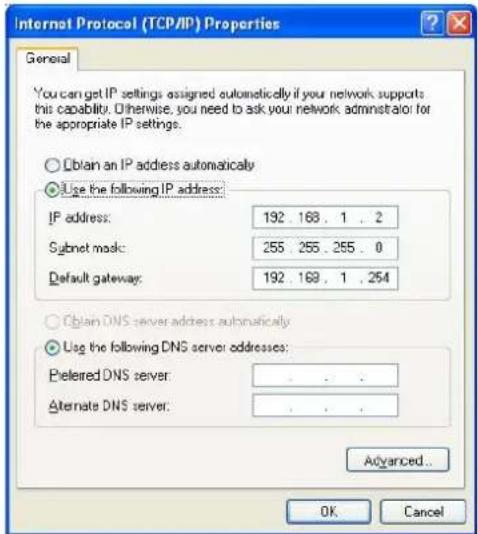
- In the following TCP/IP configuration guide, the IP address "192.168.1.2" is assumed to be your IP address if you want to specify IP addresses manually. Please DO NOT choose "192.168.1.1" for the IP address (192.168.1.1) has been set as the default IP for this device.
- The following TCP/IP configuration guide uses windows XP as the presumed operation system.
Procedures to configure IP addresses for your computer
-
If you are in Classic Start menu view, click Start > Settings > Control Panel > Network Connections. If you are in Start menu view, click Start > Control Panel > Network Connections.
-
Double click Local Area Connection.
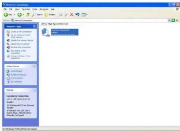
- Choose Internet Protocol (TCP/IP) and click Properties.

- You may choose "Obtain an IP address automatically"(recommend) to get IP address automatically or choose "Use the following IP address" to specify IP addresses manually. Please click the OK button after your configuration.
Wireless Router configuration setup
In order to make the whole network operate successfully, it is necessary to configure the Wireless Router through your computer has a WEB browser installed. Please follow up the steps listed below.
- Double click the Internet WEB browser icon on your desktop screen (Netscape Communicator 4.0 and Internet Explorer 3.0 or update version)
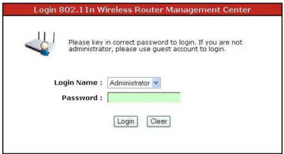
- Type 192.168.1.1 into the URL WEB address location and press Enter.

-
The Login Name and Password Required window appears.
-
Select Administrator in the Login Name drop list (default value).
- Enter admin in the Password location (default value).
- Click Login button.
4. The Graphic User Interface
After the password authorization, the Information page shows up as the home page of the Graphic User interface. You may click on each folder on left column of each page to get access to each configuration page.
Note: Please note that you should click the Save Settings button to apply your configuration to this device. You can also restore the default settings by clicking the Reset Settings button.
![IEEE 802.11n Wireless Router [INFORMATION] Network Settings Wireless Settings NAT Settings Firewall Settings Services Settings Management Information Logout SYSTEM INFORMATION System Name : ENHWI-N Firmware Version : Version 1.2 (20071101es) Host Name : Wireless.11n.Router System Time : 1970-01-01 09:08:49 Uptime : 1:08 WAN INTERFACE INFORMATION MAC Address : 00:08:54:AD:A6:DA IP Assign Type : Static IP IP Address : 10.10.13.195 Subnet Mask : 255.255.0.0 MTU Size : 1500 Default Gateway : 10.10.10.254 Primary DNS : 168.95.1.1 Secondary DNS : 168.95.192.1 LAN INTERFACE INFORMATION MAC Address : 00:08:54:AD:A6:D8 IP Address : 192.168.1.1 Subnet Mask : 255.255.255.0 DHCP Server : Active WLAN INTERFACE INFORMATION Mode : 802.11b/g/n Mixed MAC Address : 00:08:54:AD:A6:D8 SSID : Wireless-11n-Router Channel : 1 Authentication : None (Public Network)](/content/2026/05/988344/images/0c37de1c038e804bea6375dd4128c1c45a415b24fb4b7eeb4d4c1997146a8cd2.jpg)
WAN Interface Setup
This page allows users to configure those parameters for connecting to Internet. You may select the WAN Access Type from the "My Connection type" column and configure parameters for each mode.

IEEE 802.11n Wireless Router
[INFORMATION]
Network Settings
WAN Settings
LAN Settings
DoS Settings
Wireless Settings
B NAT Settings
Firewall Settings
Services Settings
Management
Information
Logout
WAN INTERFACE SETTINGS
Use this section to set the type of Internet connection. You can use the connection type as: static IP address, DHCP, or PPPoE. If you are not sure your Internet connection type, please contact your ISP Provider.
Save Settings Reset Settings
INTERNET CONNECTION TYPE
MY Connection type : ○ Static IP ◆ DHCP ○ PPPoE
Set DNS server : ○ Manually ◎ Automatically
DHCP MTU : 1500 bytes
Host Name : Wireless . 11n Router
Ping from WAN : √
Original MAC (00:08:54 AD:Δ6:DA)
WAN Ethernet MAC : ○ Manual Setting 00:00:27:88:81:18
[Clone MAC Address from your Computer]
Static IP Mode
![INTERNET CONNECTION TYPE MY Connection type : Static IP DHCP PPPoE IP Address : 10.10.13.195 Subnet Mask : 255.255.0.0 Default Gateway : 10.10.10.254 Primary DNS Server : 168.95.1.1 2nd DNS Server : 168.95.192.1 Static IP MTU : 1500 bytes Host Name : Wireless . 11n.Router Ping from WAN : WAN Ethernet MAC : Original MAC (00:08:54:AD:A6:DA ) Manual Setting 00:00:27:88:81:18 [Clone MAC Address from your Computer]](/content/2026/05/988344/images/df13af9f3c0952c8a309d09c342fe84506ede9a0161a79759edfcd44cf9f5031.jpg)
| Items Information | |
| IP Address, Subnet Mask and Default Gateway | Fill in the IP address, Subnet Mask and Default Gateway that provided by your Internet Service Provider (ISP). |
| Primary and 2^nd DNS server | To specify the Domain Name Server (DNS). Enter the DNS provided by your ISP in 1^st and 2^nd server. |
| Static IP MTU | To enable the Maximum Transmission Unit of Router setup. Any packet over this number will be chopped up into suitable size before sending. Larger number will enhance the transmission performance. Enter the MTU number in the blank to set the limitation (default 1500bytes). |
| Host Name | Name of this device. |
| Ping from WAN | Mark the check box to enable others detecting this device from WAN, and clear the checkbox to disable. |
| WAN Ethernet MAC | Select to use the following MAC as the MAC while serving Internet: Original MAC: the MAC of the device. Manual Settings: the MAC of your computer. Click on the words in the bracket to clone your computer MAC in the blank. You can also change the MAC numbers if you need. |
* Please click on the Save Settings button or the Reset Settings button on the above table to save/reset the configurations.
DHCP Client Mode
![INTERNET CONNECTION TYPE MY Connection type : ○ Static IP ◆ DHCP ○ PPPoE Set DNS server : ○ Manually ◆ Automatically DHCP MTU : 1500 bytes Host Name : Wireless , 11n.Router Ping from WAN : WAN Ethernet MAC : ◆ Original MAC (00:08:54:AD:A6:DA ) ○ Manual Setting 00:00:27:88:81:18 [Clone MAC Address from your Computer]](/content/2026/05/988344/images/b29d88cde0bbe474594d7ef93b8d7510207387bee9865b5398cba5b06c92040e.jpg)
| Items Information | |
| Set DNS server | If your DNS provide by ISP is dynamic, choose “Automatically”, if not choose “Manually” and enter the DNS provided by your ISP in DNS 1, 2. |
| DHCP MTU | To enable the Maximum Transmission Unit of Router setup. Any packet over this number will be chopped up into suitable size before sending. Larger number will enhance the transmission performance.Enter your MTU number in the text-box to set the limitation (default 1500bytes). |
| Host Name | Name of this device. |
| Ping from WAN | Mark the check box to enable others detecting this device from WAN, and clear the checkbox to disable. |
| WAN Ethernet MAC | Select to use the following MAC as the MAC while serving Internet:Original MAC: the MAC of the device.Manual Settings: the MAC of your computer. Click on the words in the bracket to clone your computer MAC in the blank. You can also change the MAC numbers if you need. |
* Please click on the Save Settings button or the Reset Settings button on the above table to save/reset the configurations.
PPPoE Mode
![INTERNET CONNECTION TYPE MY Connection type : ○ Static IP ◆ DHCP ○ PPPoE Set DNS server : ○ Manually ◆ Automatically DHCP MTU : 1500 bytes Host Name : Wireless , 11n.Router Ping from WAN : WAN Ethernet MAC : ○ Original MAC (00:08:54:AD:A6:DA ) ○ Manual Setting 00:00:27:88:81:18 [Clone MAC Address from your Computer]](/content/2026/05/988344/images/0edd77d929e276c1b043a5dd4d627eeeb85cdd0f5ce6ae3947f112f229694c8c.jpg)
| Items Information | |
| PPPoE Username and Password | Fill in the User Name and Password that provided by your ISP. The default username/password is USERNAME/PASSWORD. |
| Set DNS server | If your DNS provide by ISP is dynamic, choose “Automatically”, if not, choose “Manually” and enter the DNS provided by your ISP in DNS 1, 2. |
| PPPoE MTU | To enable the Maximum Transmission Unit of Router setup. Any packet over this number will be chopped up into suitable size before sending. Larger number will enhance the transmission performance.Enter your MTU number in the text-box to set the limitation (default 1492 bytes). |
| Host Name | Name of this device. |
| Ping form WAN | Mark the check box to enable others detecting this device from WAN, and clear the checkbox to disable. |
| WAN Ethernet MAC | Select to use the following MAC as the MAC while serving Internet:Original MAC: the MAC of the device.Manual Settings: the MAC of your computer. Click on the words in the bracket to clone your computer MAC in the blank. You can also change the MAC numbers if you need. |
* Please click on the Save Settings button or the Reset Settings button on the above table to save/reset the configurations.
To set up the configuration of LAN interface, private IP of you router LAN port and subnet mask for your LAN segment.
LAN INTERFACE SETTINGS
Use this section to set the parameter for LAN. You can use build-in DHCP server for assigning IP to the computers on LAN, this function can reduce setting time.
Save Settings
Reset Settings
ROUTER SETTINGS
The IP Address field is the IP Address that you use to access the Web-based management center. If you change the IP Address here, you may need to reconnect current IP address again.
IP Address : 192.168.1.1
Subnet Mask : 255.255.255.0
DNS Proxy : ☑ Enable
DHCP SERVER SETTINGS
Use this section to configure the built-in DHCP Server to assign IP addresses to the computers on LAN.
Enable DHCP Server : √
DHCP IP Range : 192.168.1. 100 to 192.168.1. 150
DHCP Lease Time : 86400 seconds (60..864000)
DHCP CLIENT LIST
Type
Hostname
MAC
IP
Description
Expire Time
Router Settings
| Items Information | |
| IP address | The IP of your Router LAN port (default 192.168.1.1). |
| Subnet Mask | Subnet Mask of you LAN (default 255.255.255.0). |
| DNS Proxy | DNS proxy takes DNS queries from the local network and forwards them to an Internet DNS. Mark the check box to enable DNS Proxy function or clear to disable. |
* Please click on the Save Settings button or the Reset Settings button on the above table to save/reset the configurations.
DHCP Server Settings
| Items Information | |
| Enable DHCP Server | To give your LAN Client an IP, you have to enable DHCP server. If not, manual setting up your client IP is necessary when you want to use the router as your client's default gateway. |
| DHCP IP Range | Specify the DHCP Client IP address range default (100~150). |
| DHCP Lease Time | The time for the device to recycle and give out DHCP IP (default 86400). |
* Please click on the Save Settings button or the Reset Settings button on the above table to save/reset the configurations.
DHCP Server Settings
The information of type, hostname, MAC, IP, description and expire time of the DHCP clients that have connected with this device.
The QoS (Quality of Service) Settings page provides different priority to different users or data flows.
BANDWIDTH QoS CONTROL
You can use Bandwidth Control to specify the maximum bandwidth capacity for a specific transmission to avoid network congestion and interference with others.
Bandwidth control provides a dynamic load control, which ensures that the specific transmission would not exceed the value of bandwidth capacity you have set below at any given moment.
Enable QoS Bandwidth :

TOTAL BANDWIDTH SETTINGS
Upload Bandwidth
102400
(Kbps)
Download Bandwidth
102400
(Kbps)
Save Settings
Reset Settings
BANDWIDTH QoS SETTINGS
Enable this Rule : □
Type :

Downlaod

LAN IP Adress :

Priority :
Low

Bandwidth : Min:
Min:
Max:
(Kbps)
Comment :

Action :
Change
Add
QoS SETTINGS RULE LIST
Enable
Priority
IP Address
Bandwidth
Comment
Action
Total Bandwidth Settings
You can setup the total upload/download bandwidth manually (default 102400).
Bandwidth QoS Settings
| Items Information | |
| Enable this Rule | Mark to enable the configuration, and clear to disable. |
| Type | Select the type of download or upload. |
| LAN IP Address | Fill in the MAC address that you are going to control. |
| Priority | Select the transmission priority of low, medium, high, or highest. |
| Bandwidth | Fill in the minimum and maximum bandwidth. |
| Comment | Give a definition to the LAN IP Address. |
| Action | After configuring the above settings, click Add to add a new list in the following MAC Access Control List. The Change button can be used to change the configuration. |
* Please click on the Save Settings button or the Reset Settings button on the above table to save/reset the configurations.
Bandwidth QoS Settings
Lists the Bandwidth QoS Settings you have added before. Click on the list to change configuration, or the Delete button to delete the list.
Basic Settings
You can set up the configuration of your Wireless and monitor the Wireless Clients associate with your AP.


| Items Information | |
| Enable Wireless | Mark the checkbox to enable Wireless interface or uncheck to disable. |
| Wireless Mode | To select a band for this device to match 802.11g/b/n mixed, 802.11g/b mixed, 802.11b, 802.11g, or 802.11n. |
| Country | Select the region you live. |
| Wireless Channel | Select a channel for the wireless network of this device. |
| SSID | Service set identifier for the name of the wireless network. |
* Please click on the Save Settings button or the Reset Settings button on the above table to save/reset the configurations.
Advanced Settings
You can set advanced wireless LAN parameters of this router. We recommend not changing these parameters unless you know what changes will be there on this router.
WIRELESS ADVANCE SETTINGS
Please ensure you are the system administrator and you understand every parameter. The parameters of this section effect the performance of wireless network. Be careful!
Note: WMM controls latency and jitters when transmitting multimedia content over a wireless connection.
Save Settings
Reset Settings
GENERAL WIRELESS ADVANCE SETTINGS
Hide SSID : □
Beacon Period : 100 ms (20\~1023)
DTIM Period : 1 beacon (1\~255)
RTS Threshold : 2347 bytes (0\~2347)
Fragment Threshold : 2346 bytes (256\~2346)
Tx Power : Strong
b/g Protection : Auto
Support WMM : □
802,11n WIRELESS ADVANCE SETTINGS
HT Operation Mode : Mixed
HT Channel Bandwidth : 40Mhz
HT Guard Interval : 400ns
Enable Aggregate : □
General Wireless Advance Settings
| Items Information | |
| Hide SSID | Mark to disable SSID from broadcasting. As default, this device broadcasts its SSID to allow every wireless station located within the coverage of this wireless router to discover this wireless router easily. |
| Beacon Period | The period of time a beacon is broadcasted (default 100ms). |
| DTIM Period | The beacon of a Delivery Traffic Indication Message is broadcasted (default 1 beacon). |
| RTS Threshold | If the packet size is smaller than the Request To Send threshold, the wireless router will not send this packet by using the RTS/CTS mechanism (default 2347 bytes). |
| Fragment Threshold | Specifies the maximum size of packet during the data transition. A higher value brings a better performance (default 2346 bytes) |
| Tx Power | Select the Transmission Power of very weak, weak, medium, and strong according to your demand. |
| g/b Protection | Allows the adapters search for 802.11g/b singles only. Select “Auto” to turns it on or off automatically, select “Always On” to support protection or select “Always Off” to disable this function. |
| Support WMM | To enable/disable Wi-Fi Multimedia function. |
* Please click on the Save Settings button or the Reset Settings button on the above table to save/reset the configurations.
802.11n Wireless advance Settings
| Items Information | |
| HT Operation Mode | Select the mixed or green field mode as the Hyper Throughput operation mode. |
| HT Channel Bandwidth | Select the 40MHz or 20MHz as the channel bandwidth. |
| HT Guard Interval | Select 400ns or 800ns as the interval time. |
| Enable HT TX Aggregate MSDU | Mark to enable Hyper Throughput TX Aggregate MAC Service Data Unit, and clear to disable. |
* Please click on the Save Settings button or the Reset Settings button on the above table to save/reset the configurations.
Security Settings
The Security function protects your wireless network from invasion. We provide WEP and WPA encryption to secure your wireless network. As default, the authentication is configured as safe mode. Please select None/WEP/WPA (Personal) in the drop list. If you select none, any data will be transmitted without encryption and any station can access the router.
WIRELESS SECURITY SETTINGS
Use this section to configure the wireless settings for your Router. Please note that changes made on this section may also need to be duplicated on your Wireless Client.
Save Settings
Reset Settings
WIRELESS SECURITY MODE
To protect your privacy, you can configure wireless security features. This device supports two wireless security modes including WEP and WPA-Personal. WEP is the original wireless encryption standard. WPA provides a higher level of security. WPA-Personal does not require an authentication server.
No security protection, everybody can connect to this router anytime. Be careful! This means your network is public, hackers can hack your computer easily!
WEP Configuration

| Items Information | |
| Authentication | Open: Wireless AP can associate with this wireless router without WEP encryption.Shared Key: Wireless AP can associate with this wireless router only with WEP encryption. |
| Default Key ID | Select to use the WEP key value of 1,2,3 or 4 as in the following settings. |
| WEP Key 1, 2, 3 and 4 | Select ASCII or Hex to setup the key value (default 012345). |
* Please click on the Save Settings button or the Reset Settings button on the above table to save/reset the configurations.
WPA Configuration

| Items Information | |
| WPA Mode | Select the option in the drop list to enable modes of auto, WPA only, or WPA2 only. |
| WPA Encryption | Select TKIP / AES, TKIP or AES as WPA encryption. |
| Pre-Shared Key | Select the key format of Pass Phrase or Hex.Enter the Pre-Shared Key according to the key format you select (default 01234567). |
| WPA ReKey Method | To enable/disable WPA rekey method by time or by packet. |
| WPA ReKey Interval | Enter the numbers to setup the WPA rekey interval. |
| Pairwise Master Key Cache Interval | Select 1, 5, 10, 20, 30, 60, or 120 minuets as the cache interval time. |
| Pre-Authentication Support | Mark this checkbox to enable pre-authentication function, and clear to disable. |
* Please click on the Save Settings button or the Reset Settings button on the above table to save/reset the configurations.
Access Control
To restrict the Number of Access authentication of Stations, set up the control list in this page. You may select "Allow Listed" to allow those allowed MAC addresses or select "Deny Listed" to ban those MAC addresses from accessing to this device.
WIRELESS MAC ACCESS CONTROL
If you choose 'Allowed Listed', only those clients whose wireless MAC addresses in the access control list will be able to connect to your Access Point. When 'Deny Listed' is selected, these wireless clients on the list will not be able to connect to the router.

MAC ACCESS CONTROL SETTINGS

MAC ACCESS CONTROL LIST
Enable
Client MAC
Description
Action
CURRENT ASSOCIATED CLIENT LIST
MAC address
Description
MAC Access Control Settings
| Items Information | |
| Enable this Rule | Mark to enable the configuration, and clear to disable. |
| MAC Address | Fill in the MAC address that you are going to control. |
| Description | Give a definition to the MAC Address. |
| Action | After configuring the above settings, click Add to add a new list in the following MAC Access Control List. The Change button can be used to change the configuration. |
* Please click on the Save Settings button or the Reset Settings button on the above table to save/reset the configurations.
MAC Access Control List
Lists the MAC Access Control Settings you have added before. Click on the list to change configuration, or the Delete button to delete the list.
Current Associated Client List
Lists the current associated client connected to this device. Click on the list to add it into the MAC Access Control List then to do more configurations on it.
Wireless Distribution System allows the router to communicate with other APs wirelessly. To make it work, you must ensure that these APs and the Router are in the same Channel and add these APs MAC Address and Comment values into the WDS list.
WIRELESS DISTRIBUTION SYSTEM (WDS)
Wireless Distribution System uses wireless media to communicate with other APs, like the Ethernet does. To do this, you must set these APs in the same channel and set MAC address of other APs which you want to communicate with in the table and then enable the WDS.
Note: Before connecting to other Access Point, please make sure they use the same channel. [Change Current Channel]
Save Changes
Reset Changes
WDS SETTINGS
WDS Mode :
Disabled

(default:disabled)
AP+WDS (AP Repeater)
WDS SETTINGS
Enabling WDS function, the peer Wds APs are listed in WDS MAC list field below according to the MAC address.
WDS Mode :
AP+WDS (AP Repeater)
(default:disabled)
WDS Encryption Type :
None

WDS Partner 1 MAC :
WDS Partner 2 MAC :
WDS Partner 3 MAC :
WDS Partner 4 MAC :



WDS (AP Bridge)
WDS SETTINGS
Enabling WDS function, the peer Wds APs are listed in WDS MAC list field below according to the MAC address. In this mode, AP will not send beacon out and will not deal with probe request packets, therefore STA will not possible to connect with it.
WDS Mode : WDS (AP Bridge) (default:disabled)
WDS Encryption Type :

WDS Partner 1 MAC :

WDS Partner 2 MAC :

WDS Partner 3 MAC :

WDS Partner 4 MAC :

Auto (AP Bridge)
WDS SETTINGS
Enabling WDS function and auto learning from WDS packet. Please note that there should be at least one AP filled in WDS list.
WDS Mode : Auto (AP Bridge) (default:disabled)
WDS Encryption Type :

[Wireless Security setting Page] You must setup WEP encryption in wireless security page.
| Items Information | |
| WDS | Select the option in the drop list to enable AP+WDS (AP Repeater), WDS (AP Bridge) or Auto (AP Bridge) as WDS format. |
| Encryption Type | Select the option in the drop list to enable WEP, WPA/TKIP, and WPA/AES encryption types. If you select None, any data will be transmitted without encryption and any station can access the router. |
| WPA Encryption Key | For encryption type of WPA/TKIP and WPA/AES, you have to fill in the WPA encryption key. Please use Pass Phrase (8~32bytes) key format. |
| WDS AP MAC List | For encryption type of WPA/TKIP and WPA/AES, you have to fill in the WDS AP MAC. You can fill up to 4 sets of WDS AP MAC lists. |
* Please click on the Save Settings button or the Reset Settings button on the above table to save/reset the configurations.
WPS (WiFi PROTECTED SETUP)
WiFi Protected Setup was designed to ease setup of security enabled WiFi networks in the home and small office environment. It supports methods that are familiar to most users to configure a network and enable security, like pushing a button or entering a PIN. The new system, which will be incorporated in Windows Vista, will work with computers, gateways peripherals, and consumer electronics.
WiFi Protected Setup : ☑ Enable (default:disabled)
WPS CONNECTION SETTINGS

WPS INFORMATION
WPS Configured : N/A WPS Status : Idle SSID : Wireless-11n-Router Auth Mode : Open WPAPSK : 01234567 Refresh
WPS Connection Settings
| Items Information | |
| WPS Config Method | PIN method (Personal Identification Number): read the PIN from either a sticker on the new STA or a display.PBC method (Push Button Communication): in which the user simply has to push a button, either an actual or virtual one, on both the AP and the new STA. |
| Add Enrollee PIN Code | Fill in the PIN code to enrollee device. Click on Build WPS Connection button to execute. |
* Please click on the Save Settings button or the Reset Settings button on the above table to save/reset the configurations.
WPS Information
Shows the information of WPA configured, status, SSID, authentication mode, and pre-shared key. Click on Refresh button to refresh the information.
NAT Settings
NAT (Network Address Translation) involves re-writing the source and/or destination addresses of IP packets as they pass through a Router or firewall. NAT enable multiple hosts on a private network to access the Internet using a single public IP address.
NAT (NETWORK ADDRESS TRANSLATION)
Use this section to set the advance NAT settings. You can build VPN passthrough here. Virtual DMZ and virtual server are used to provide Internet services without sacrificing unauthorized access to its local private network. Such as Web (HTTP) servers, FTP servers, SMTP (e-mail) servers or DNS servers.
Save Settings
Reset Settings
NAT & ALG SETTINGS
Enable NAT : √
IPSec Pass Through : √
PPTP Pass Through : √
L2TP Pass Through : √
Non-standard FTP port :

ALG (Application Layer Gateway Service) SETTINGS
SIP ALG : □
NetMeeting ALG : □
Window Messenger File
Transfer ALG :
StarCraft/Battle.net ALG : □

NAT & ALG Settings
Click on the checkbox to enable NAT function, IPSec (IP Security), PPTP (point-to-point tunneling protocol), and L2TP (layer 2 tunneling protocol) pass through on Virtual Private Network (VPN), or clear to disable. Fill in the port number in the Non-standard FTP port blank if you need.
ALG Settings
Click on the checkbox to enable SIP (session initiation protocol), NetMeeting, Window Messenger File Transfer, and StarCraft/Battle.net ALG.
After marking or clearing the enable checkbox, it takes 5 seconds for this device to refresh the page.
VIRTUAL SERVER
Use this page to configure virtual server and redirect remote users that access from web or FTP services via the public (WAN) IP address to local servers in the LAN network.
We redirects the external service request to the appropriate server within the LAN network according to the requested service (TCP/UDP port number).
Enable Virtual Server √
VIRTUAL SERVER SETTINGS
Enable this Rule : □
Application Select : Custom
WAN Port :
Protocol : Both
LAN Server IP :
LAN PORT:
Action : Change Add
VIRTUAL SERVER MAPPING LIST
Enable
WAN Port
Protocol
LAN IP
LAN Port
Action
Virtual Server Settings
| Items Information | |
| Enable this Rule | Mark to enable the configuration, and clear to disable. |
| Application Select | Select an application for your demand. |
| WAN Port | Fill in the port number of WAN. |
| Protocol | Select the protocol type of TCP, UDP or Both |
| LAN Server IP | Fill in the IP of your LAN Server. |
| LAN Port | Fill in the port number of LAN. |
| Action | After configure the above settings, click Add to add a new list in the following IP Filter Rule List. The Change button can be used to change the configuration. |
* Please click on the Save Settings button or the Reset Settings button on the above table to save/reset the configurations.
Virtual Server Mapping List
Lists the Virtual Server Settings you have added before. Click on the list to change configuration, or the Delete button to delete the list.
Virtual DMZ
The virtual DMZ (Demilitarized Zone) is used to enable protocols, which need to open ports on the router. The router will forward all unspecified incoming traffic to the host specified in this page. To configure it, mark to enable and then enter the Host IP (private IP address) and click Save Settings to enact the setting.
VIRTUAL DEMILITARIZED ZONE (Virtual DMZ)
A Demilitarized Zone is used to provide Internet services without sacrificing unauthorized access to its local private network. Typically, the virtual DMZ host contains devices accessible to Internet traffic, such as Web (HTTP) servers, FTP servers, SMTP (e-mail) servers and DNS servers.
Save Settings
Reset Settings
VIRTUAL DMZ SETTINGS
Enable Virtual DMZ :

Virtual DMZ IP Adress :

IP Filter
The Wireless Router could filter the outgoing packets for security or management consideration. You can set up the filter against the IP addresses to block specific internal users from accessing the Internet. After marking or clearing the enable checkbox, it takes 5 seconds for this device to refresh the page.
IP FILTER
Entries in this table are used to restrict certain types of data packets from your local network to Internet through the Gateway. Use of such filters can be helpful in securing or restricting your local network.
Enable IP Filter √
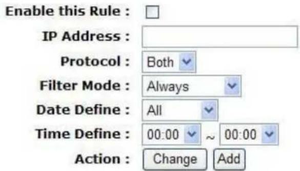
IP FILTER SETTINGS
IP FILTER RULE LIST
Enable
IP Address
Protocol
Mode
Day
Time
Action
IP Filter Settings
| Items Information | |
| Enable this Rule | Mark to enable the configuration, and clear to disable. |
| IP Address | Fill in the IP address that you are going to filter. |
| Protocol | Select the protocol type of TCP, UDP or Both |
| Filter Mode | Select the filter mode of Always or by Schedule |
| Date Define Time Define | For filter mode of by Schedule, you have to define the filter date and time. |
| Action | After configure the above settings, click Add to add a new list in the following IP Filter Rule List. The Change button can be used to change the configuration. |
* Please click on the Save Settings button or the Reset Settings button on the above table to save/reset the configurations.
IP Filter Rule List
Lists the IP Filter Settings you have added before. Click on the list to change configuration, or the Delete button to delete the list.
Port Filter
The firewall could not only obstruct outside intruders from intruding your system, but also restricting the LAN users. Port filtering restricts certain type of data packets from your LAN to Internet through the router. After marking or clearing the enable checkbox, it takes 5 seconds for this device to refresh the page.
PORT FILTER
Entries in this table are used to restrict certain types of data packets from your local network to Internet through the Gateway. Use of such filters can be helpful in securing or restricting your local network.
Enable Port Filter √
PORT FILTER SETTINGS
Enable this Rule : □
Application Select : Custom
Port Range : \~
Protocol : Both
| Items Information | |
| Enable this Rule | Mark to enable the configuration, and clear to disable. |
| Port Range | Fill in the port range that you are going to filter. The valid numbers are 1~65535. |
| Protocol | Select the protocol type of TCP, UDP or Both |
| Filter Mode | Select the filter mode of Always or by Schedule |
| Date Define Time Define | For filter mode of by Schedule, you have to define the filter date and time. |
| Action | After configure the above settings, click Add to add a new list in the following IP Filter Rule List. The Change button can be used to change the configuration. |
* Please click on the Save Settings button or the Reset Settings button on the above table to save/reset the configurations.
Port Filter Rule List
Lists the Port Filter Settings you have added before. Click on the list to change configuration, or the Delete button to delete the list.
MAC Filter
The Wireless Router could filter the outgoing packets for security or management consideration. You can set up the filter against the MAC addresses to block specific internal users from accessing the Internet. After marking or clearing the enable checkbox, it takes 5 seconds for this device to refresh the page.
PORT FILTER
Entries in this table are used to restrict certain types of data packets from your local network to Internet through the Gateway. Use of such filters can be helpful in securing or restricting your local network.
Enable Port Filter √
PORT FILTER SETTINGS
Enable this Rule : □
Application Select : Custom
Port Range : \~
Protocol : Both
| Items Information | |
| Enable this Rule | Mark to enable the configuration, and clear to disable. |
| MAC Address | Fill in the MAC address that you are going to filter. |
| Filter Mode | Select the filter mode of Always or by Schedule |
| Date Define Time Define | For filter mode of by Schedule, you have to define the filter date and time. |
| Action | After configure the above settings, click Add to add a new list in the following IP Filter Rule List. The Change button can be used to change the configuration. |
* Please click on the Save Settings button or the Reset Settings button on the above table to save/reset the configurations.
MAC Filter Rule List
Lists the MAC Filter Settings you have added before. Click on the list to change
configuration, or the Delete button to delete the list.
Website Filter
The Website Filter allows users to prevent certain website from accessing by users in LAN. This filter will block those websites that contain certain keywords. After marking or clearing the enable checkbox, it takes 5 seconds for this device to refresh the page.
WEBSITE FILTER
Web Site filter is used to deny LAN users from accessing the internet. It blocks those URLs which contain keywords listed below. (EX: google; www.google.com or 72.14.203.99)
Enable WebSite Filter √
Client IP Address : (0.0.0.0 means no limit)
URL or Key Word :
Action : Change Add
| Items Information | |
| Enable this Rule | Mark to enable the configuration, and clear to disable. |
| IP Address | Fill in the local IP address that you want to restrain it from serving the filtering websites. |
| Website or Key Word | Fill in the name or keywords of the website to block. |
| Action | After configure the above settings, click Add to add a new list in the following Website Filter Rule List. The Change button can be used to change the configuration. |
* Please click on the Save Settings button or the Reset Settings button on the above table to save/reset the configurations.
Website Filter Rule List
Lists the Website Filter Settings you have added before. Click on the list to change configuration, or the Delete button to delete the list.
DDNS Settings
DDNS (Dynamic Domain Name Server) service allows users to connect to this device via a fixed and easy-to-remember hostname.
DDNS (DYNAMIC DOMAIN NAME SERVICES)
Dynamic DNS is a service, that provides you with a valid, unchanging, internet domain name (an URL) to go with that (possibly everchanging) IP address.
Save Settings
Reset Settings
DDNS SETTINGS
Enable DDNS :

Service Provider :
DynDns.org
Domain Name :
USER.dyndns.org
User Name/Email :
USER
Password/Key :

Confirm Password :

| Items Information | |
| Enable DDNS | Mark to enable the configuration, and clear to disable. |
| Service Provider | The website that provides DDNS service. Please select DynDns.org, No-IP.com or TZO from the drop list. |
| Domain Name | The hostname that you have applied for the device. |
| User Name/Email | DDNS login account. For DynDNS users, please fill in your user name; for No-IP and TZO users, please fill in your email address (default USER). |
| Password/Key | The password of your DDNS service account (default PASSWORD). |
| Confirmed Password | Retype the password to confirm. |
* Please click on the Save Settings button or the Reset Settings button on the above table to save/reset the configurations.
UPnP Settings
The UPnP (Universal Plug and Play) service allows devices to connect seamlessly and to simplify the implementation of networks in the home (data sharing, communications, and entertainment) and corporate environments. This page allows user to monitor the information of UPnP clients. Mark or clear the checkbox to enable or disable UPnP IGD, and then click Save Settings to enact your settings.
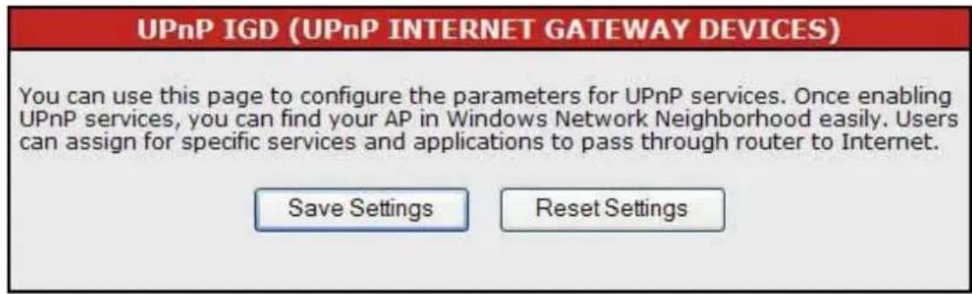

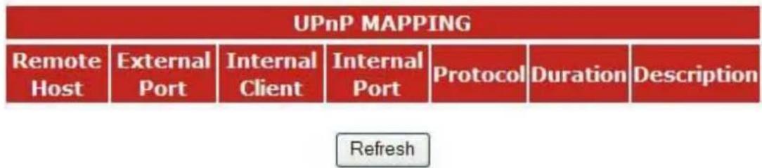
The System Log Settings page shows the information of the current activities on the router.

![SYSTEM LOG SETTINGS System Log ✓ Enable Log Status Cleanup when reboot ✓ Log Message Size 4 ✓ (Kbytes) Remote Log ✓ Enable Remote Log Server Address your.syslog.server Remote Log Server Port 514 (Standard : 514) Log to Remote and Local □ Enable [Local System Log ] You can check your local system log here.](/content/2026/05/988344/images/7805856d46a3c719eaa1043422f5f93478513b851911d964933e43bad150c755.jpg)
| Items Information | |
| System Log | Mark to enable the configuration, and clear to disable. |
| Log Type | Select “cleanup when reboot” or “save log message” as the log type. |
| Log Message Size | Select the log message size of 4, 8, or 32 Kbytes. |
| Remote Log | Mark to enable the following configuration, and clear to disable. |
| Remote Log Server Address | Fill in the sever address for remote log. |
| Remote Log Server Port | Fill in the sever port for remote log. |
| Log to Remote and Local | To enable/disable log to remote and local |
* Please click on the Save Settings button or the Reset Settings button on the above table to save/reset the configurations.
Date/Time Settings
This page allows users to configure the date and time of the router. To specify manually, select the date and time from the drop list and click the Save Settings button. To synchronize time from a timeserver, please enter the update interval hour numbers, select an NTP server from the drop list or manually enter a private NTP server and then click the Save Settings button. Mark the Daylight Saving checkbox if you want to apply it on system time.
NTP CLIENT (NETWORK TIME PROTOCOL)
You can maintain the system time by synchronizing with a public time server over the Internet.
Save Settings
Reset Settings
Manual Time Setting
DATE & TIME SETTINGS
SYNC TIME : ◎ Manual Time Setting ○ NTP Time Server
Time Zone : (GMT-08:00) Pacific Time
Daylight Saving : □
System Date: Year 2005 Mon 01 Day 01
System Time : Hour 09 Min 40 Sec 38
NTP Time Server
DATE & TIME SETTINGS
SYNC TIME : ◯ Manual Time Setting ◎ NTP Time Server
Time Zone : (GMT-08:00) Pacific Time
Daylight Saving : □
Update Interval : 24 hours
General NTP Server : None
Private NTP Server :
Admin Account
The admin account is the account for accessing this configuration interface. In this page, you can reset the password of the admin account and setup a designated IP to remote control this device.

| Admin Accounts | |||
| Access Level | Password | Confirm Password | Action |
| administrator✓ | Change | ||
Remote Administration
| Items Information | |
| Remote Control | Mark this checkbox to allow remote PC accessing the configuration interface of this router. |
| HTTP port for remote | The HTTP port for accessing this management interface (default 8080). |
| Remote Control IP | The permitted IP for accessing. The default IP 0.0.0.0 allows all IP addresses form accessing. |
| Update button | Click on this button to update your setting. |
Admin Accounts
| Items Information | |
| Access Level | Select an access level of admin or guest. |
| Password | The new password for the admin account |
| Confirm Password | Fill in the new password again |
| Action | Click Change button to apply the new password. |
The Ping Test page allows the administrator to test the connecting status of Internet. Fill in the IP then click on the Ping Test button to view the result information.
PING TEST (PACKET INTERNET GROPER TEST)
This useful diagnostic utility can be used to check if a computer is on the Internet. It sends ping packets and listens for replies from the specific host. Enter in a host name or the IP address that you want to ping and click Ping.
Destination host name/IP address : 192.168.1.1
Ping
PING TESTING RESULT
PING 192.168.1.1 (192.168.1.1): 56 data bytes 84 bytes from
192.168.1.1: icmp_seq=0 ttl=64 time=0.8 ms 84 bytes from
192.168.1.1: icmp_seq=1 ttl=64 time=0.5 ms 84 bytes from
192.168.1.1: icmp_seq=2 ttl=64 time=0.5 ms --- 192.168.1.1 ping
statistics --- 3 packets transmitted, 3 packets received, 0% packet
loss round-trip min/avg/max = 0.5/0.6/0.8 ms
Config
The Config page allows users to backup and download the configuration status of the device or restore the factory default configuration.
CONFIG SETTINGS
This page allows you to save current settings to a file or upload the settings from the file which was saved before. You can also reset the current configuration to factory default.
Save Settings to File :
Save
Load Settings from File :
Upgrade
Reset Settings to Default :
Reset to Default
| Items Information | |
| Save Settings to File | Click on the Save button to save settings. |
| Load Settings from File | Click Browse to select the file and then click Reload to start the process. Please wait for it to complete. |
| Reset Settings to Default | Click Reset to Default to start the process and it will be completed till the status LED starts blinking. |
Firmware Upgrade
Sometimes a new firmware may be issued to upgrade the system of this device. You could upgrade the firmware you got in this page. To upgrade the firmware, please click on the Browse button, locate the firmware in your computer and then click the Upload button to execute.
FIRMWARE UPGRADE
This page allows you to upgrade firmware to new version.
Firmware File Browse... Upgrade
Please note:
Do not power off the device during upgrading because it may crash the system.
Information
System Information
This information page shows the current settings of this device. You could check if the parameters match your configuration.
SYSTEM INFORMATION
System Name: ENHWI-N
Firmware Version : Version 1.2 (20071101es)
Host Name: Wireless.11n.Router
System Time: 1970-01-01 09:44:34
Uptime:1:44
WAN INTERFACE INFORMATION
MAC Address: 00:08:54:AD:A6:DA
IP Assign Type : Static IP
IP Address: 10.10.13.195
Subnet Mask: 255.255.0.0
MTU Size: 1500
Default Gateway: 10.10.10.254
Primary DNS : 168.95.1.1
Secondary DNS : 168.95.192.1
LAN INTERFACE INFORMATION
MAC Address: 00:08:54:AD:A6:D8
IP Address : 192.168.1.1
Subnet Mask: 255.255.255.0
DHCP Server : Active
WLAN INTERFACE INFORMATION
Mode: 802.11b/g/n Mixed
MAC Address: 00:08:54:AD:A6:D8
SSID : Wireless-11n-Router
Channel: 1
Authentication : N/A
Packet Statistics
This page allows users to get information of data transferring condition, and monitor the status and performance of this router including interface, receiving/sending packets, and receiving/sending errors.
PACKET STATISTIC
Some information of netstat shows here. You are able to view the amount of receiving and sending packets that pass through the network interfaces. The traffic counter resets after rebooting the device.
| Interface | Recv Pkts | Send Pkts | Recv Errs | Send Errs |
| LAN | 3909 | 3955 | 0 | 0 |
| WAN | 0 | 656 | 0 | 0 |
| Wired_LAN | 3915 | 3944 | 0 | 0 |
| LOOKUP | 473 | 473 | 0 | 0 |
| Wireless_LAN | 31771 | 5931 | 0 | 0 |
Routing Table
This page shows the routing table in this router. Users can get connecting information including destination, gateway, net mask, flags, metric, ref, use and interface.
ROUTING TABLE
A routing table contains the information necessary to forward a packet along the best path toward its destination. Each packet contains information about its origin and destination. The table then provides the device with instructions for sending the packet to the next hop on its route across the network.
| Destination | Gateway | Netmask | Flags | Metric | Ref | Use | Iface |
| 192.168.1.0 | 0.0.0.0 | 255.255.255.0 | U | 0 | 0 | 0 | br0 |
| 10.10.0.0 | 0.0.0.0 | 255.255.0.0 | U | 0 | 0 | 0 | eth0 |
| 0.0.0.0 | 10.10.10.254 | 0.0.0.0 | UG | 0 | 0 | 0 | eth0 |
System Log
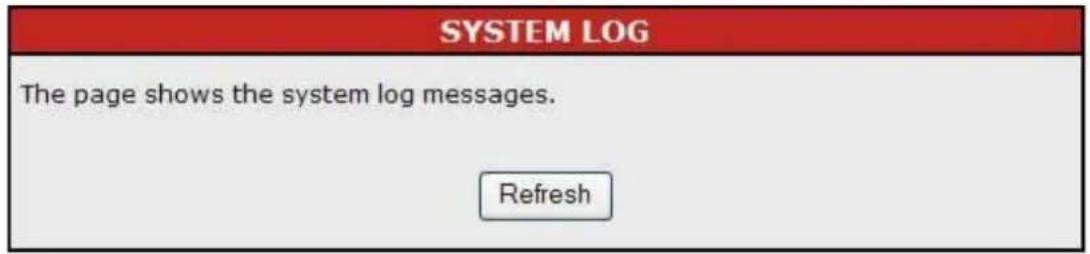
This page shows the system log information. Click the Refresh button to refresh the list.
| SYSTEM LOG MESSAGES LIST | |
| Time | Info |
Logout
Logout
Click the Logout button to log out the admin account from this system

Reboot
Click the reboot button to restart this system. This may cost 1 minute to restart the system. Please wait upon restarting.

| Standard | IEEE 802.11nIEEE 802.11g,IEEE 802.11b,IEEE 802.3,IEEE 802.3u |
| Interface | LAN: 4 port 10/100Mbps Ethernet, RJ-45WAN: One RJ45 port3* 802.11n/g/b wireless reverse SMA detachable antenna |
| WAN Connection | Ethernet 10/100 Mbps |
| Cable Connections | RJ-45 (10BASE-T): Category 3,4,5 UTPRJ-45 (100BASE-TX): Category 5 UTP |
| Transmission Mode | Auto-Negotiation (Full-duplex, Half-duplex) |
| LED indications | 1*Power,1*WAN,4*LAN,1*WLAN |
| Security | 64/128-bit WEP, WPA, WPA2 |
| Receiver Sensitivity | 11Mbps-91dBm, 54Mbps-78dBm,300mbps -69dBm |
| Transmit Power | 11Mbps 19dBm, 54Mbps 16dBm,11n 20MHz and 11n 40MHz 16dBm |
| Range Coverage | Indoor 35~100 metersOutdoor 100~300meters. |
| Emission | FCC CLASS B, CE |
| Operating Temperature | 00 ~ 400C (320 ~ 1040F) |
| Operating Humidity | 10% - 90% RH non-condensing |
| Power Supply | External Power Adapter, 12VDC/ 1A |

- ENCORE
- ELECTRONICS
- ENHWI-N
- ENCORE 802.11n Wireless Router
- FCC Certifications
- IMPORTANT NOTE:
- FCC Radiation Exposure Statement:
- CE Mark Warning
- Trademarks:
- Table of Contents
- Unpacking Information
- Introduction To Wireless Router
- General Description
- Key Features
- The Front Panel
- LED Definitions
- - Status LED
- - WLAN LED
- • LAN LEDs
- - WAN LED
- - Setup Button
- The Rear Panel
- Power Connection
- Installing And Using Wireless Router
- Network configuration setup
- Computer configuration setup
- Note:
- Procedures to configure IP addresses for your computer
- Wireless Router configuration setup
- The Graphic User Interface
- WAN Interface Setup
- IEEE 802.11n Wireless Router
- [INFORMATION]
- WAN INTERFACE SETTINGS
- INTERNET CONNECTION TYPE
- DHCP Client Mode
- PPPoE Mode
- LAN INTERFACE SETTINGS
- ROUTER SETTINGS
- DHCP SERVER SETTINGS
- DHCP CLIENT LIST
- BANDWIDTH QoS CONTROL
- TOTAL BANDWIDTH SETTINGS
- BANDWIDTH QoS SETTINGS
- QoS SETTINGS RULE LIST
- Basic Settings
- Advanced Settings
- WIRELESS ADVANCE SETTINGS
- GENERAL WIRELESS ADVANCE SETTINGS
- 802,11n WIRELESS ADVANCE SETTINGS
- 802.11n Wireless advance Settings
- Security Settings
- WIRELESS SECURITY SETTINGS
- WIRELESS SECURITY MODE
- WEP Configuration
- Access Control
- WIRELESS MAC ACCESS CONTROL
- MAC ACCESS CONTROL SETTINGS
- MAC ACCESS CONTROL LIST
- CURRENT ASSOCIATED CLIENT LIST
- WIRELESS DISTRIBUTION SYSTEM (WDS)
- WDS SETTINGS
- AP+WDS (AP Repeater)
- WDS (AP Bridge)
- Auto (AP Bridge)
- WPS (WiFi PROTECTED SETUP)
- WPS CONNECTION SETTINGS
- WPS INFORMATION
- NAT Settings
- NAT (NETWORK ADDRESS TRANSLATION)
- NAT & ALG SETTINGS
- ALG (Application Layer Gateway Service) SETTINGS
- ALG Settings
- VIRTUAL SERVER
- VIRTUAL SERVER SETTINGS
- VIRTUAL SERVER MAPPING LIST
- Virtual DMZ
- VIRTUAL DEMILITARIZED ZONE (Virtual DMZ)
- VIRTUAL DMZ SETTINGS
- IP Filter
- IP FILTER SETTINGS
- IP FILTER RULE LIST
- Port Filter
- PORT FILTER SETTINGS
- Port Filter Rule List
- MAC Filter
- MAC Filter Rule List
- Website Filter
- Website Filter Rule List
- DDNS Settings
- DDNS (DYNAMIC DOMAIN NAME SERVICES)
- UPnP Settings
- Date/Time Settings
- NTP CLIENT (NETWORK TIME PROTOCOL)
- Manual Time Setting
- DATE & TIME SETTINGS
- NTP Time Server
- Admin Account
- PING TEST (PACKET INTERNET GROPER TEST)
- PING TESTING RESULT
- Config
- CONFIG SETTINGS
- Firmware Upgrade
- Information
- System Information
- WAN INTERFACE INFORMATION
- LAN INTERFACE INFORMATION
- WLAN INTERFACE INFORMATION
- Packet Statistics
- PACKET STATISTIC
- Routing Table
- System Log
- Logout
- Reboot
Brand : ENCORE
Model : ENHWI-N
Category : Router