
Z670 - Security Camera Clover Electronics - Free user manual and instructions
Find the device manual for free Z670 Clover Electronics in PDF.


| Product Type | Security Camera |
| Brand | Clover Electronics |
| Model | Z670 |
| Image Sensor | 1/3-inch CMOS |
| Resolution | 720p HD (1280x720) |
| Lens | 3.6mm fixed lens |
| Night Vision | Up to 30m with IR LEDs |
| Motion Detection | Yes, configurable |
| Video Output | Composite video (BNC) |
| Power Supply | 12V DC, 500mA (adapter included) |
| Power Consumption | ~5W |
| Weather Rating | IP66 weatherproof |
| Dimensions | 75mm x 60mm x 55mm (without bracket) |
| Weight | 400g (camera only) |
| Mounting | Wall or ceiling mountable |
| Cable Length | Integrated 18m BNC/power combo cable |
| Operating Temperature | -10°C to 50°C |
| Cleaning | Wipe with a soft, dry cloth. Do not use solvents. |
| Safety | Disconnect power before cleaning or installation. |
| Spare Parts | Power adapter, mounting screws, user manual |
| Repairability | Limited; contact manufacturer for service |
| General Information | Refer to user manual for detailed setup and troubleshooting. |
Frequently Asked Questions - Z670 Clover Electronics
User questions about Z670 Clover Electronics
0 question about this device. Answer the ones you know or ask your own.
Ask a new question about this device
Download the instructions for your Security Camera in PDF format for free! Find your manual Z670 - Clover Electronics and take your electronic device back in hand. On this page are published all the documents necessary for the use of your device. Z670 by Clover Electronics.
USER MANUAL Z670 Clover Electronics
- To prevent fire or shock hazard, do not expose the camera to rain or moisture.
- To avoid electrical shock, do not open the case of this product.
- Operate this product with the system such as COM22168, LCD2088, TFT2284C, TFT2288C and LCD261616 or by using only the power supply included.
- Do not overload electrical outlets or extension cords, this can result in fire or electric shock.
- Keep this product away from strong magnetic fields.
- Do not expose this product in direct sunlight or strong reflected rays.
- Refer servicing to qualified personnel only.
- Do not change or modify this product, the warranty terms will be voided.
2. FEATURES
- High Resolution: 480 TV Lines
- Up to 30 Times Zoom
- Color image automatically turns into black and white images at night (Day/Night)
- Distinguish Bills in a Cash Register
- View objects in more detail
- Auto White balance/Gain Control/Backlight Compensation
3. ZOOM CAMERA

[Fig.3-1 Rear view of the zoom camera]
- Video Output/DC power Input (6 pin Din)
This is a 6pin Din connector for outputting video signals and for DC 12V input from the system such as COM22168, LCD2088, TFT2284C, TFT2288C and LCD261616.
Note:
When the 6pin Din is connected, do not apply 12V DC to the DC IN Jack ③ and connect the BNC video out ②.
- Video Output (BNC)
This is a BNC connector for outputting video signals.
Note:
When the BNC connector ② is used, do not connect the 6pin Din cable to the 6pin Din jack①.
- 12V DC IN Jack
When the 6pin Din connector ① is not connected, apply DC12V 500 mA regulated voltage to the DC IN Jack ③.
- Power LED
It will be lit in green when the 6pin Din ① is connected or DC voltage is applied to the DC IN Jack.
- Terminal Block for RS485
This camera has a terminal block for 2 wires in polarity.
Connect the provided twisted pair cable to this terminal block and the other end to the DVR system (refer to Chapter 5.0 Installation for more detail).
- Menu, Tele/Wide, Near/Far
Refer to Section 4.1 On the zoom camera for more detailed information)
4. SETUP
4.1 On the Zoom Camera
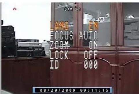
-Press the Menu button on the rear of the camera and then the following Menu will display.
The Menu button enables users to access the menu screen and to go back to the previous menu or exit from the present screen.
[Fig.4-1 Menu settings]
LANGUAGE
Choose “LANG (LANGUAGE)” in the Menu shown in Fig.4-1 by pressing “TELE”/“WIDE” button and select “EN (English)” by pressing “NEAR”/“FAR” button.
- FOCUS
Choose “FOCUS” in the Menu shown in Fig.4-1 by pressing “TELE”/“WIDE” button and choose one among MANU (Manual), KCTL and AUTO by pressing “NEAR”/“FAR” button.
· ZOOM
Choose “ZOOM” in the Menu shown in Fig.4-1 by pressing “TELE”/“WIDE” button and select “ON” or “OFF” by pressing “NEAR”/“FAR” button.
If the "ON" is selected, the zooming function will be operated properly.
If the "OFF" is selected, the zooming function won't be working.
- LOCK
Choose “LOCK” in the Menu shown in Fig.4-1 by pressing “TELE”/“WIDE” button and select “ON” or “OFF” by pressing “NEAR”/“FAR” button.
If the "ON" is selected, the zooming function won't be working.
If the "OFF" is selected, the zooming function will be operated properly.
· ID
Choose “ID” in the Menu shown in Fig.4-1 by pressing “TELE”/“WIDE” button and choose a number among “0” to “255” by pressing “NEAR”/“FAR” button.
-Press the Menu button again and then the following Menu will be displayed.

[Fig.4-2 Menu settings]
- WHITE BALANCE (WB)
Choose “WB (WHITE BALANCE)” in the Menu shown in Fig.4-2 by pressing “TELE”/“WIDE” button and choose one among AUTO, OUT DOOR, INDOOR and LAMP by pressing “NEAR”/“FAR” button.
- IRIS
Choose “IRIS” in the Menu shown in Fig.4-2 by pressing “TELE”/“WIDE” button and choose one among AUTO, FIX, NIGHT and MOVE by pressing “NEAR”/“FAR” button.
- AGC
Choose “AGC” in the Menu shown in Fig.4-2 by pressing “TELE”/“WIDE” button and select “ON” or “OFF” by pressing “NEAR”/“FAR” button.
- MIRROR (MIRR)
Choose “MIRROR” in the Menu shown in Fig.4-2 by pressing “TELE”/“WIDE” button and select “ON” or “OFF” by pressing “NEAR”/“FAR” button.
You can view the mirror image when the “ON” is selected and the normal image when the “OFF” is selected.
- BAUD RATE
Choose “BAUD” in the Menu shown in Fig.4-2 by pressing “TELE”/“WIDE” button and choose 2400 BPS (Bit Per Second) among 2400, 4800 and 9600 by pressing “NEAR”/“FAR” button.
- DEFAULT (DEFLT)
Choose “DEFAULT (DEFLT)” in the Menu shown in Fig.4-2 by pressing “TELE”/“WIDE” button and press the Menu button twice to set the factory default values.
Tips for Quick Setup on the zoom camera:
- You can operate the zoom camera without changing any settings.
- The factory default ID is “000”, but choose a number among “0” to “255” as an ID if necessary.
- Do not change the Baud Rate which is 2400.
4.2 On the DVR system
- Click on the SETUP icon on the Menu Bar as shown below.

[Fig.4-3 Menu Bar]
- Click the “CAMERA” in the Setup Menu and then the Camera Menu will be displayed as shown in Fig.4-4.

[Fig.4-4 Camera Menu]
- Click the “PAN/TILT (PELCO D)” button on the channel you wish to install the zoom camera and then the PAN/TILT Menu will be displayed as shown in Fig.4-5.

[Fig.4-5 PAN/TILT Menu]
- Settings in the PAN/TILT Menu
(Refer to System manual section 7-4.5 on page 90 for more detail) - Click the PTZ ID button in the PAN/TILT Menu shown in Fig.4-5, then the On Screen Keyboard will show up.
-
Delete the current PTZ ID with the button and enter a new ID by using On Screen Keyboard, and then click "OK" button to set with the new ID. The ID should be the same ID as the zoom camera has (e.g.: If the ID of the zoom camera is set to 7, the PTZ ID in the PAN/TILT Menu as shown in Fig.4-5 should be entered 7).
-
Click the “PAN/TILT & REMOTE” button in the PAN/TILT menu shown in Fig.4-5, then the vendor lists will show up. Select “PELCO” on the vendor lists by clicking the mouse and then the protocol “PELCO D” will display.
- Click the “BAUD RATE” button in the PAN/TILT menu and choose 2400bps among 1200bps, 2400bps, 4800bps, 9600bps, 19200bps, 38400bps, 57600bps and 115200bps on the Baud Rate pop-up window by clicking the mouse.
- Do not change the settings for Data Bits, Stop Bits and Parity Bits.
Tips for Quick Setup on the DVR system:
- Enter the same ID as the zoom camera has.
e.g.1: if the ID of the zoom camera is "000", enter "0" in the PTZ ID box. e.g.2: if the ID of the zoom camera is "007", enter "7" in the PTZ ID box. - The protocol should be "PELCO D".
- Choose the Baud Rate (communication speed) 2400bps on the pop-up menu.
5. INSTALLATION
- Connect the RED and BLUE colored wire of the Data Cable (Twisted Pair Cable) to the “+” and “-” terminals on the rear of the camera and the DVR system as shown in Fig5-1. Refer to the instruction manual of DVR system relevant to the location of “+” and “-” terminals for RS485.

[Fig.5-1 Installation]
- To connect the bared copper wire on the end of the RED and BLUE colored wire, push the terminal with “-”driver (2mm) until inserting it into the round hole as shown in Fig.5-2.

[Fig.5-2 Connecting bared copper wire]
- Connect the one end of 60' 6pin Din cable to the Din jack on the rear of the zoom camera and the other end of cable to the DIN jack that the settings for PAN/TILT menu on the DVR system has been completed.
-Be sure that the two arrows on the camera and the cable should be aimed at each other.
-Do not apply DC 12V to the DC Jack and connect the BNC video out on the zoom camera when the 6 pin Din Cable is connected.
- Make sure that the video quality is normal and the power LED on the rear of the zoom camera is lit in green when the DVR system is turned ON for the next step.
- Attach the mounting bracket to the desired location on the wall or ceiling, wherever you want to install the zoom camera. Locate a wall stud or ceiling joist and secure the mounting bracket using the supplied screws.
- Attach the zoom camera to the mounting bracket and firmly tighten the swivel.
6. OPERATION
- Click the PAN/TILT button on the Menu bar in the Live mode to access the zoom camera as shown in Fig. 6-1 and then the PAN/TILT Controller will be displayed as shown in Fig. 6-2.

[Fig.6-1 PAN/TILT button]
- Click the Channel button in Fig. 6-2 and select the Channel number of zoom camera on the pop-up screen.

[Fig.6-2 PAN/TILT CONTROL window]
- Click and hold the “+” or “-” button for Zoom In/Out until getting the best quality of objects. If the Focus is set to “AUTO” on the zoom camera, it won’t be adjusted by the “+” or “-” button.
The function of PAN/TILT and PRESET are not available on the Zoom Camera.
7. TROUBLE SHOOTING
If the product does not function properly, please check the following points before contacting the service center.
| Problems | Causes |
| No picture -Check connection of 60' cable | between the DVR system and the camera-Check the included AC power supply for retail packaging. |
| No zoom In/Out -Check the data cable | -Check the terminal block for wrong wiring (polarity)-Check the settings such as ID, Baud Rate on the camera and the DVR system |
| Picture flickering -Strong spot light in the field of view | |
| Dim picture, picture too dark or too bright | -Adjust brightness on the DVR system |
and
8. SPECIFICATIONS
Image pickup device SONY Color CCD
TV
system
NTSC
Resolution
480
TV
lines
Minimum illumination 0.5 Lux
Video output 1.0v p-p composite @75 ohms
S/N
ratio
More
than
48db
Gamma
characteristics
0.45
Electronic Shutter Speed 1/60 to 1/100,000sec
Zoom
Up
to
30X
Max.
White
Balance
Auto
Gain
Control
Auto
Control
Interface
RS485
Baud
Rate
2400BPS
Focus Adjustment
High Speed Auto or Manual Adjustment
Current consumption
250 mA @ DC12V
Power
supply
DC
12V
Operational temperature
-10°C to 50°C RH95% Max
Dimensions
60 (W) x 60 (H) x 120(L) mm
Weight
0.9
Lbs
9. PACKAGE INCLUDED
1-Zoom camera
1-Mounting bracket
1-60' 6pin Din cable for COM22168
(Not included in the retail packaging)
1-60' BNC/Power to BNC/Power for retail packaging
(Not included in the COM22168)
1-61' Data cable (Twisted Pair Cable)
1-AC power supply (ADT120500R: not included in the COM22168)
1-Instruction manual
1-Warranty registration card
1-Warnig label
10. OPTIONAL ACCESSORIES
CA100
100' Extension cable
CN020
Coupler for cable extension
CA100BP
100' BNC/Power to BNC/Power extension cable w/BNC coupler
11. LIMITED 1 YEAR WARRANTY
This warranty gives the original purchaser specific legal rights and you may also have other rights, which may vary from state to state. If our products do not function because of any defect in material or workmanship, we will repair it for free for 1 year on parts and labor from the date of original purchase. This warranty does not cover modification, abuse, incidental or consequential damages unless the state of owner's residence specially prohibits limitations on incidental or consequential damages.
12. HOW TO OBTAIN FACTORY SERVICE
- Original purchaser must fill out the warranty card and mail it to the factory with the model number, serial number and the date of purchase.
- We will repair or replace, and return the system to the owner under this limited warranty.
- Please pack the system carefully and securely using the original packing materials, and send it prepaid and insured to: 13073 E. 166th St, Cerritos, CA 90703.
- Please include a check for \$15.00 to cover the cost of return postage and handling. If the system is returned within the warranty period, please include a proof of purchase. If the system is out of warranty, you will receive an estimate of the repair cost for your approval before repair work will be started.
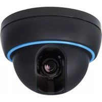
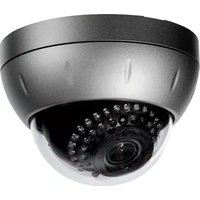
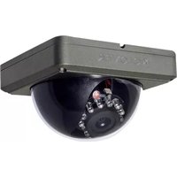
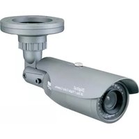
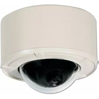
Brand : Clover Electronics
Model : Z670
Category : Security Camera