
IPR-10G2-SDI - Video Converter AJA - Free user manual and instructions
Find the device manual for free IPR-10G2-SDI AJA in PDF.


| Product Type | Video Over IP Converter/Transceiver |
| Model | IPR-10G2-SDI |
| Brand | AJA |
| Dimensions (W x D x H) | Approx. 1.5 x 8.0 x 6.5 inches (38 x 203 x 165 mm) |
| Weight | About 2.5 lbs (1.13 kg) |
| Power Supply | 12V DC, 2.5A (external adapter included) |
| Power Consumption | < 30W |
| Video Input | 1x 12G-SDI (BNC) |
| Video Output | 1x 12G-SDI (BNC), 1x 10 Gigabit Ethernet (SFP+) |
| Supported Video Formats | SD, HD, 3G, 6G, 12G-SDI up to 4K/UltraHD |
| Network Interface | 10GBASE-R (SFP+ slot, fiber or copper) |
| Network Protocols | RTP, RTSP, SMPTE ST 2110, NMOS IS-04/05 |
| Control Interface | Ethernet (1GbE), RS-422, GPIO (D-sub 9) |
| Environmental Fee | Includes $5.00 recycling fee in applicable regions |
| Operating Temperature | 32°F to 104°F (0°C to 40°C) |
| Storage Temperature | -4°F to 140°F (-20°C to 60°C) |
| Humidity | 10% to 90% (non-condensing) |
| Compliance | FCC Class A, CE, RoHS |
| Warranty | 2 years limited |
| Maintenance | Clean with dry soft cloth. Avoid liquids. No user-serviceable parts. |
| Repairability | Contact AJA support for service. Do not disassemble. |
| Package Contents | Main unit, power adapter, mounting brackets, quick start guide |
Frequently Asked Questions - IPR-10G2-SDI AJA
User questions about IPR-10G2-SDI AJA
0 question about this device. Answer the ones you know or ask your own.
Ask a new question about this device
Download the instructions for your Video Converter in PDF format for free! Find your manual IPR-10G2-SDI - AJA and take your electronic device back in hand. On this page are published all the documents necessary for the use of your device. IPR-10G2-SDI by AJA.
USER MANUAL IPR-10G2-SDI AJA
10 GigE IP Mini-Converters
SMPTE 2110 IP Transmit/Receive

Installation and Operation Guide
Trademarks
AJA® and Because it matters. are registered trademarks of AJA Video Systems, Inc. for use with most AJA products. AJATM is a trademark of AJA Video Systems, Inc. for use with recorder, router, software and camera products. Because it matters. is a trademark of AJA Video Systems, Inc. for use with camera products.
Corvid Ultra ® , Io ® , Ki Pro ® , KONA ® , KUMO ® , ROI ® and T-Tap ® are registered trademarks of AJA Video Systems, Inc.
AJA Control Room™, KiStor™, Science of the Beautiful™, TruScale™, V2Analog™ and V2Digital™ are trademarks of AJA Video Systems, Inc.
All other trademarks are the property of their respective owners.
Copyright
Copyright © 2022 AJA Video Systems, Inc. All rights reserved. All information in this manual is subject to change without notice. No part of the document may be reproduced or transmitted in any form, or by any means, electronic or mechanical, including photocopying or recording, without the express written permission of AJA Video Systems, Inc.
Contacting AJA Support
When calling for support, have all information at hand prior to calling. To contact AJA for sales or support, use any of the following methods:
| Telephone +1.530.271.3190 |
| FAX +1.530.271.3140 |
| Web https://www.aja.com____ |
| Support Email support@aja.com____ |
| Sales Email sales@aja.com____ |
Contents
Notices 2
Trademarks 2
Copyright 2
Contacting AJA Support 2
Chapter 1 – Introduction .....5
Overview. 5
Pre-Built System Configuration Modes for IPR-10G2. . . . . . . . . . . . . . . . . . . . 6
10 GigE IP Mini-Converters Features 7
IPT-10G2-SDI 7
IPT-10G2-HDMI 8
IPR-10G2-SDI 8
IPR-10G2-HDMI 9
Abbreviated Feature Comparison Chart 10
Workflow Diagrams and I/O Connections ..... 10
Simplified Block Diagrams and Logic Diagrams 14
Frequently Asked Questions 15
System Requirements. 15
Control LAN, Ready, Link/Act, and Lock LED Behavior. 15
Installation Overview 15
Initial Setup By Web Browser 16
Initial Setup By AJA eMini-Setup 16
Hardware Installation 17
Settings Retained. 17
REST API Documentation 17
Chapter 2 – eMini-Setup ..... 18
Overview....18
Acquiring eMini-Setup 18
eMini-Setup Documentation 18
Installing eMini-Setup 19
PC Installation 19
Mac Installation 20
Running eMini-Setup 20
PC Startup 21
Mac Startup 21
Operating eMini-Setup....21
Control LAN Tab Screen 22
Media LAN 1 Tab Screen 23
Media LAN 2 Tab Screen 24
Update Tab Screen. 25
Firmware Update Procedure....25
Info Tab Screen 26
Chapter 3 – 10 GigE IP Mini-Converters Web Interface. . . . . . . . 27
Overview. 27
Remote Control Overview 27
Networking Option – Using Only the Media LAN Port for Control and Media
Settings 27
Web Browser via Ethernet 28
General Screen Information 28
Status Screen 30
IPT-10G2-SDI 30
IPR-10G2-HDMI 32
Config Screen....33
IPT-10G2-SDI 33
IPR-10G2-HDMI 40
Presets Screen 49
Presets Screen Controls....49
Network Screen 50
Firmware Screen 53
Downloading and Installing Updated Firmware 53
Booting the 10 GigE IP Mini-Converters from the Safeboot Firmware . . . 54
Appendix A – Specifications .....56
IPT-10G2-SDI Tech Specs 56
IPT-10G2-HDMI Tech Specs 58
IPR-10G2-SDI Tech Specs....59
IPR-10G2-HDMI Tech Specs 61
Appendix B – Safety and Compliance .....64
Warranty and Liability Information....72
Index. 73
Chapter 1 – Introduction

Overview
AJA 10 GigE IP Mini-Converters are designed for point of use applications for encoding, transport, reception and decoding of IP based video sources. Rugged, compact and fanless, the 10 GigE IP Mini-Converters provide the bridge between Baseband and IP video for a range of applications, such as sending and receiving video over IP from remote facilities in post production, source monitoring, digital signage, and video walls. 10 GigE IP Mini-Converters ease the cost of extensive monitoring distribution in a facility.
The 10 GigE IP Mini-Converter Transmitters take baseband HDMI or SDI input and encode the data as SMPTE 2110. The embedded audio associated with the video stream is also encoded to SMPTE 2110. Alternatively, analog audio can be encoded and sent with the video stream instead.
The 10 GigE IP Mini-Converter Receivers decode SMPTE 2110 and format the data for either HDMI or SDI output. The audio associated with the video stream is extracted, synchronized, and then embedded into the HDMI or SDI signal as well as output on a stereo analog RCA audio output.
All UltraHD rates (23.98, 24, 25, 29.97, 30, 50) can be received only by the IPR-10G2-HDMI.
The IPR-10G2-HDMI can provide RGB (rather than YCbCr) to a compatible monitor if the monitor or other sink device indicates this availability via EDID.
Pre-Built System Configuration Modes for IPR-10G2
There is a set of pre-built system configuration modes, or "system modes," available from the System Mode control on the Config page of the IPR-10G2 web UI. These pre-built System Modes are designed to save you time so that you can get your unit up and running quickly.
Each System Mode is built for a specific type of use case, taking into account factors such as network conditions, protection requirements, timing, and latency considerations.
Please see "System Modes" on page 41 for more detailed information.
NOTE: The System Modes are available only for the IPR-10G2-SDI and IPR-10G2-HDMI units; they are not needed on the IPT-10G2-SDI and IPT-10G2-HDMI units since the transmitter's functionality is simpler.
On a high level, the five pre-built System Modes are described as follows:
PTP Low Latency
- Appropriate under ideal network conditions
- Fastest method of moving data through the device (does not require signal processing)
- Provides the least amount of packet-level and frame-level protection
- Remote sender and AJA IPR-10G2 receiver are locked to PTP
PTP Protected
- Provides the highest amount of packet-level and frame-level protection, including redundancy support with ST 2022-7
• Maximum latency due to longer signal processing chain - Remote sender and AJA IPR-10G2 receiver are locked to PTP
Gateway
- Bridges between PTP and Reference Video timed domains
- Provides frame-level protection
• Moderate latency due to signal processing chain
Gateway Protected
- Bridges between PTP and Reference Video timed domains
- Provides the highest amount of packet-level and frame-level protection, including redundancy support with ST 2022-7
• Maximum latency due to longer signal processing chain
Asynchronous
- Intended as a setup environment or troubleshooting and demo tool
- Not for production
- When unable to lock to PTP or when experiencing problems with Reference In, uses Video In to verify that video is being received from source address
- Provides frame-level protection (no packet-level protection)
• Moderate latency due to signal processing chain
Advanced
Unlike the five pre-built System Modes just described, each of which are "safe," Advanced Mode does not guard against a user applying contradictory settings that could provide unpredictable results.
Characteristics of Advanced Mode include the following:
- For custom configurations
- Has no native default settings
- Can be used to iterate and expand upon the five pre-built System Modes described above
- Provides free-range access to:
- Video Clock Mode
- Packet Protection Mode
- Frame Sync Mode
- System Mode
• Audio Sample Rate Converter
- When selected, Advanced Mode will retain the settings of the previously selected System Mode, and the user may proceed to customize settings as desired. This means that any of the System Modes can be modified using Advanced Mode and then saved as a Preset on the Presets screen.
NOTE: When working with Advanced Mode, if the configuration settings become problematic, you can always "revert" to one of the five pre-built System Modes to get the unit running again with established internally compatible settings.
10 GigE IP Mini-Converters Features
IPT-10G2-SDI
- SMPTE ST 2110 audio, video transmitter including support for ST 2022-7
• Essence support: SMPTE 2110-10, 2110-20, 2110-30
• Rugged, quiet, fanless design - 2x 10 GigE SFP+ cages for media LAN with status light (for media transport, control, and timing input), SFP+ modules not included)
- 1x 1 GigE RJ45 socket for control LAN with status light
- Complete control interface on any web browser from a built-in web server
- Customizable control with AJA REST API
- Control supported over dedicated management Ethernet port and in-band over media ports
- NMOS Rx discovery and control according to standards IS-04 v1.3 and IS-05 v1.1
- Ember+ control (no discovery, control only)
- AJA REST API control (discovery via SSDP or MDNS)
- LLDP (Link Layer Discovery Protocol)
- 1x 3G-SDI Input
- 1x 3G-SDI Loop Out
• Support for HD up to 1080 60p, YCbCr 4:2:2 - Concealment of errors due to packet loss
• Full 10-bit pixel processing pipeline - Embedded SDI audio input (up to 16 channels)
• 2x RCA analog audio input - 1x BNC Reference Out, allowing incoming baseband sources to be locked to PTP timing
- Frame Sync
- 1x mini-USB port for initial network configuration with AJA eMini-Setup software (alternative setup method)
• 5-year international warranty and support
IPT-10G2-HDMI
- SMPTE ST 2110 audio, video transmitter including support for ST 2022-7
• Essence support: SMPTE 2110-10, 2110-20, 2110-30
• Rugged, quiet, fanless design - 2x 10 GigE SFP+ cages for media LAN with status light (for media transport, control, and timing input), SFP+ modules not included)
• 1x 1 GigE RJ45 socket for control LAN with status light - Complete control interface on any web browser from a built-in web server
-
Customizable control with AJA REST API
• Control supported over dedicated management Ethernet port and in-band over media ports -
NMOS Rx discovery and control according to standards IS-04 v1.3 and IS-05 v1.1
- Ember+ control (no discovery, control only)
- AJA REST API control (discovery via SSDP or MDNS)
• LLDP (Link Layer Discovery Protocol)
- Dedicated HDMI transmitter with full size (standard type A) HDMI 1.4b (24/30-bits per pixel) input up to HD 60p, 4:2:2, 10-bit, YCbCr
- Concealment of errors due to packet loss
• Full 10-bit pixel processing pipeline - Embedded SDI audio input (up to eight channels)
• 2x RCA analog audio input - 1x BNC Reference Out, allowing incoming baseband sources to be locked to PTP timing
- Frame Sync
- 1x mini-USB port for initial network configuration with AJA eMini-Setup software (alternative setup method)
• 5-year international warranty and support
IPR-10G2-SDI
- SMPTE ST 2110 audio, video receiver including support for ST 2022-7
• Essence support: SMPTE 2110-10, 2110-20, 2110-30
• Rugged, quiet, fanless design - 2x 10 GigE SFP+ cages for media LAN with status light (for media transport, control, and timing input), SFP+ modules not included)
• 1x 1 GigE RJ45 socket for control LAN with status light - Complete control interface on any web browser from a built-in web server
- Customizable control with AJA REST API
-
Control supported over dedicated management Ethernet port and in-band over media ports
-
NMOS Rx discovery and control according to standards IS-04 v1.3 and IS-05 v1.1
- Ember+ control (no discovery, control only)
-
AJA REST API control (discovery via SSDP or MDNS)
-
USB Keyboard Control for Recalling Presets
• 2x 3G-SDI Output (mirrored)
• Support for HD up to 1080 60p, YCbCr 4:2:2 -
Concealment of errors due to packet loss
• Full 10-bit pixel processing pipeline -
Embedded SDI audio output (up to 16 channels)
• 2x RCA analog audio output - 1x BNC Reference for analog/tri-level reference input, allowing baseband output to be locked to the facility baseband clock (instead of PTP)
- 1x mini-USB port for initial network configuration with AJA eMini-Setup software (alternative setup method)
- 5-year international warranty and support
IPR-10G2-HDMI
- SMPTE ST 2110 audio, video receiver including support for ST 2022-7
• Essence support: SMPTE 2110-10, 2110-20, 2110-30
• Rugged, quiet, fanless design - 2x 10 GigE SFP+ cages for media LAN with status light (for media transport, control, and timing input), SFP+ modules not included)
• 1x 1 GigE RJ45 socket for control LAN with status light - Complete control interface on any web browser from a built-in web server
- Customizable control with AJA REST API
- Control supported over dedicated management Ethernet port and in-band over media ports
- NMOS Rx discovery and control according to standards IS-04 v1.3 and IS-05 v1.1
- Ember+ control (no discovery, control only)
- AJA REST API control (discovery via SSDP or MDNS)
• USB Keyboard Control for Recalling Presets
- Dedicated HDMI receiver with full size (standard type A) HDMI 1.4b (24/30-bits per pixel) output up to HD 60p, 4:2:2, 10-bit, YCbCr/RGB, or 2K up to 2048 60p, YCbCr 4:2:2 or UltraHD 30p, 4:2:2, 10-bit, YCbCr, or UltraHD 50p, 4:2:0, 8-bit, YCbCr
• ST 2022-7 is supported up to HD 1080p (UltraHD not supported)
- Concealment of errors due to packet loss (error concealment functionality supported up to 1080p 60, UltraHD not supported)
• Full 10-bit pixel processing pipeline (except for UHD p50)
- Embedded HDMI audio output (up to eight channels)
• 2x RCA analog audio output
- 1x BNC Reference for analog/tri-level reference input, allowing baseband output to be locked to the facility baseband clock (instead of PTP)
- 1x mini-USB port for initial network configuration with AJA eMini-Setup software (alternative setup method)
- 5-year international warranty and support
Abbreviated Feature Comparison Chart
| Model | UltraHD Support | 2K Support | Reference Functions | System Modes | 2022-7 support | RGB 4:4:4 10-bit |
| IPT-10G2-SDI Ref Out Up to | 1080 p60 | |||||
| IPT-10G2-HDMI Up to | 2048 p60 | Ref Out Up to | 1080 p60 | |||
| IPR-10G2-SDI Up to | 2048 p60 | Ref In Supported Up to | 2048 p60 | |||
| IPR-10G2-HDMI Up to UHD p50 | Up to 2048 p60 | Ref In Supported Up to | 2048 p60 | Up to 1080 p60 |
Workflow Diagrams and I/O Connections
Figure 1. Example Workflow Diagram for the IPT-10G2-SDI

flowchart
graph TD
    A["3G-SDI Recorder/Player or other SDI source"] -->|Ref In| B["Media Server"]
    B -->|1x 3G-SDI| C["PTP Generator"]
    C -->|HD (up to 60p) Input/Output redundant IP feeds| D["10 GigE Switch"]
    D -->|10 GigE Input/Output| B
    B -->|1x SDI| E["HD SDI Remote Monitor"]
    E -->|1x SDI| F["PTP Generator"]
    F -->|HD (up to 60p) Input/Output redundant IP feeds| D
    D -->|HD (up to 60p) Input/Output redundant IP feeds| E
    A -->|Black Burst/Tri-level Sync based on PTP Clock| G["IPT-10G2-SDI"]
    G -->|Ref Out| H["Rebase"]
    H --> A
Figure 2. IPT-10G2-SDI Connections
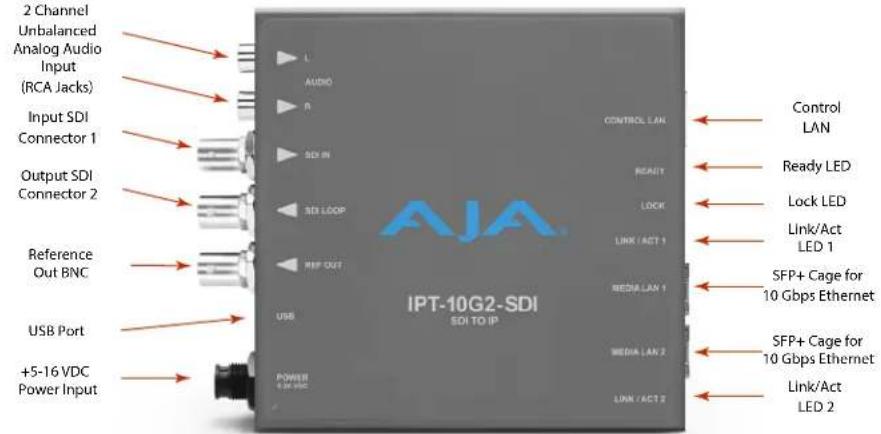
Figure 3. Example Workflow Diagram for the IPT-10G2-HDMI
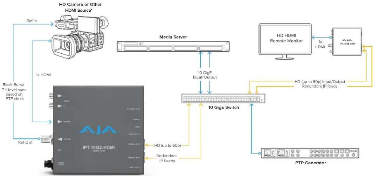
flowchart
graph TD
    A["HD Camera or Other HDMI Source*"] -->|Ref In| B["Media Server"]
    B -->|1x HDMI| C["PTP Generator"]
    C -->|HD (up to 60p) Input/Output Redundant IP feeds| D["10 GigE Switch"]
    D -->|10 GigE Input/Output| B
    B -->|1x HDMI| E["HD HDMI Remote Monitor"]
    E -->|1x HDMI| F["PTP Generator"]
    F -->|HD (up to 60p) Input/Output Redundant IP feeds| D
    D -->|HD (up to 60p) Input/Output Redundant IP feeds| C
    C -->|Ref Out| G["IPT-10G2-HDMI"]
    G --> H["Black Burst/ Tri-level sync based on PTP clock"]
Figure 4. IPT-10G2-HDMI Connections

Figure 5. Example Workflow Diagram for the IPR-10G2-SDI

flowchart
graph TD
    A["IPR-10G2-SDI"] -->|HD (up to 60p)| B["10 GigE Switch"]
    A -->|Redundant IP feeds| C["10 GigE"]
    A -->|Black Burst/ Tri-level sync generator| D["HD SDI Monitor"]
    A -->|1x SDI 3G-SDI| E["1x SDI"]
    A --> F["Audio/Video/Control Unit"]
    G["Media Server"] -->|10 GigE Input/Output| H["10 GigE Switch"]
    I["PTP Generator"] -->|10 GigE Input/Output| H
    H --> J["10 GigE Switch"]
    K["Recorder/Player or other SDI destination"] --> L["Computer"]
Figure 6. IPR-10G2-SDI Connections

Figure 7. Example Workflow Diagram for the IPR-10G2-HDMI
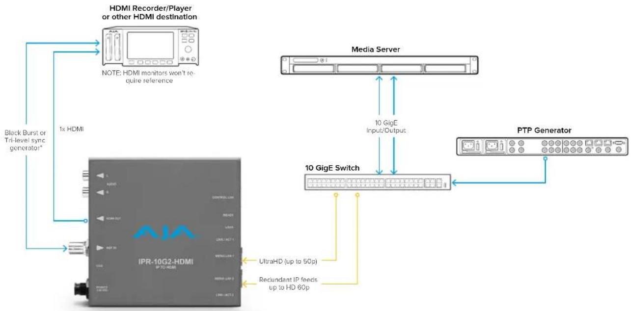
flowchart
graph TD
    A["IPR-10G2-HDMI"] -->|UltraHD (up to 50p)| B["Media Server"]
    A -->|Reclundant IP feeds up to HD 60p| C["10 GigE Switch"]
    A -->|Black Burst or Tri-level sync generator*| D["HDMI Recorder/Player or other HDMI destination"]
    B -->|10 GigE Input/Output| C
    C --> E["PTP Generator"]
    D --> F["NOTE: HDMI monitors won't require reference"]
Figure 8. IPR-10G2-HDMI Connections
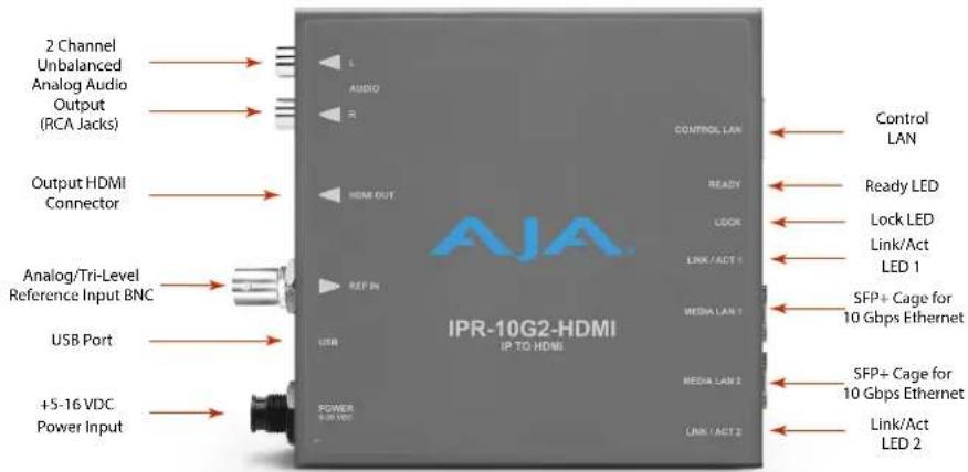
Simplified Block Diagrams and Logic Diagrams
Figure 9. IPT-10G2-SDI/HDMI Simplified Block Diagram
IPT-10G2-SDI / IPT-10G2-HDMI

flowchart
graph LR
    A["Reference Output"] --> B["Video over IP Processing"]
    C["Control LAN"] --> B
    D["HDMI Input with 8 Ch Embedded Audio"] --> B
    E["SDI Input with 16 Ch Embedded Audio SDI Loop Through"] --> B
    F["2-Channel RCA Analog Audio Input"] --> B
    G["USB Port (connect to PC or Mac) For initial setup of network interfaces"] --> B
    B --> H["Video"]
    B --> I["Audio"]
    H --> J["Video over IP Transmitter"]
    I --> J
    J --> K["Media LAN 1"]
    J --> L["Media LAN 2"]
    style A fill:#f9f,stroke:#333
    style C fill:#f9f,stroke:#333
    style D fill:#ccf,stroke:#333
    style E fill:#ccf,stroke:#333
    style F fill:#ccf,stroke:#333
    style G fill:#ccf,stroke:#333
    style H fill:#cff,stroke:#333
    style I fill:#cff,stroke:#333
    style J fill:#ffc,stroke:#333
    style K fill:#cfc,stroke:#333
    style L fill:#cfc,stroke:#333
Figure 10. IPR-10G2-SDI/HDMI Simplified Block Diagram
IPR-10G2-SDI / IPR-10G2-HDMI
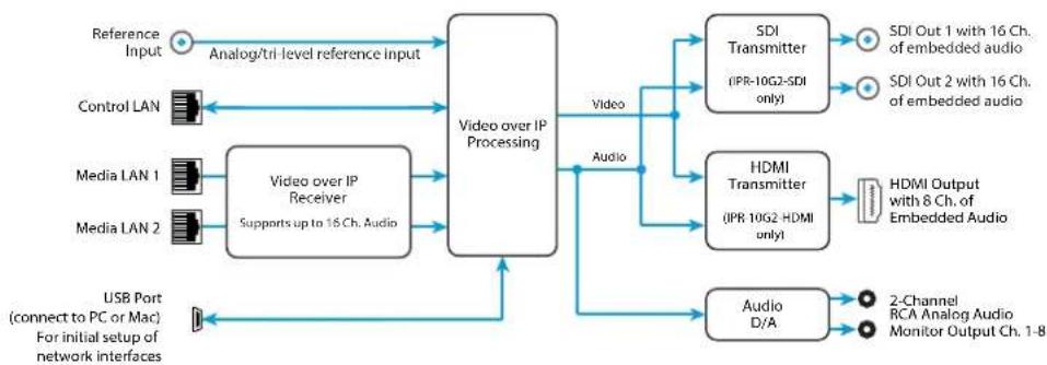
flowchart
graph LR
    A["Reference Input"] --> B["Analog/tri-level reference input"]
    C["Control LAN"] --> D["Video over IP Receiver"]
    E["Media LAN 1"] --> D
    F["Media LAN 2"] --> D
    G["USB Port (connect to PC or Mac) For initial setup of network interfaces"] --> H["Video over IP Processing"]
    D --> I["Video"]
    H --> J["Audio"]
    I --> K["SDI Transmitter (IPR-10G2-SDI only)"]
    I --> L["HDMI Transmitter (IPR 10G2-HDMI only)"]
    K --> M["SDI Out 1 with 16 Ch. of embedded audio"]
    K --> N["SDI Out 2 with 16 Ch. of embedded audio"]
    L --> O["HDMI Output with 8 Ch. of Embedded Audio"]
    M --> P["2-Channel RCA Analog Audio Monitor Output Ch. 1-8"]
    N --> P
    Q["Audio D/A"] --> P
Figure 11. IPR-10G2-SDI/HDMI Simplified Logic Diagram
IPR-10G2-SDI / IPR-10G2-HDMI
Simplified Logic Diagram

flowchart
graph TD
    A["Media LAN 1"] --> B["Packet Protection (Supporting ST 2022-7 when dual SFPs in use)"]
    C["Media LAN 2"] --> D["window size applies here"]
    B --> E["Framesync"]
    D --> E
    E --> F["Baseband Output"]
    G["PTP"] --> H["Output Video Clock"]
    I["Ref"] --> H
    J["Video In"] --> H
    K["Free Run"] --> H
    H --> E
    style A fill:#f9f,stroke:#333
    style C fill:#f9f,stroke:#333
    style B fill:#ccf,stroke:#333
    style D fill:#ccf,stroke:#333
    style E fill:#cfc,stroke:#333
    style F fill:#fcc,stroke:#333
    style G fill:#fff,stroke:#333
    style I fill:#fff,stroke:#333
    style J fill:#fff,stroke:#333
    style K fill:#fff,stroke:#333
    style H fill:#fff,stroke:#333
    style H fill:#fff,stroke:#333
Frequently Asked Questions
To access responses to frequently asked questions about the 10 GigE IP Mini-Converters, please use the following links:
- https://www.aja.com/products/ipt-10g2-sdi#support
- https://www.aja.com/products/ipt-10g2-hdmi#support
- https://www.aja.com/products/ipr-10g2-sdi#support
- https://www.aja.com/products/ipr-10g2-hdmi#support
System Requirements
Remote computer configuration and control is accomplished using the 10 GigE IP Mini-Converters' internal web server. A macOS X or Windows computer with a web browser installed is all that is required. Additionally, initial configuration using eMini-Setup will require a USB port between the host computer and the 10 GigE IP Mini-Converter.
NOTE: Chrome and Firefox are the preferred web browsers for control on Windows. Safari is the preferred web browser for control on macOS. Other web browsers may work, but AJA cannot guarantee consistent operation for all web browsers or web browser versions.
Control LAN, Ready, Link/Act, and Lock LED Behavior
The Control LAN LED illuminates to indicate a link. Blinking indicates activity.
The Ready LED illuminates green when the unit has finished powering up and is ready to use.
The Link/Act LED 1 and Link/Act LED 2 behavior is as follows:
- Off - No SFP+ module present
- Red - SFP+ module present, no link
- Green - Link is up
- Green flash - Link is up and there is Tx or Rx activity
The Lock LED behavior is as follows:
- Off - No Precision Time Protocol (PTP) is detected
• Red - A PTP error is detected
• Yellow and flashing - Locking Phase 1 - Yellow - Locking Phase 2
- Green and flashing - Locking Phase 3
- Green - Signal is locked
NOTE: Achieving locked status may take 5 or more minutes depending on network jitter behavior. The output of the unit will still function during the locking period.
Installation Overview
Detailed instructions are provided in "Chapter 2 – eMini-Setup" on page 18 and "Chapter 3 – 10 GigE IP Mini-Converters Web Interface" on page 27.
As an overview, however, there are two methods available for initial setup for 10 GigE IP Mini-Converters:
-
Using a web browser on the host computer connected to the same network as the 10 GigE IP Mini-Converter, or
-
Using the AJA eMini-Setup application running on the host computer that is directly connected to the 10 GigE IP Mini-Converter via USB.
Initial Setup By Web Browser
NOTE: Chrome and Firefox are the preferred web browsers for control on Windows. Safari is the preferred web browser for control on macOS. Other web browsers may work, but AJA cannot guarantee consistent operation for all web browsers or web browser versions.
10 GigE IP Mini-Converters require a network connection for initial configuration, control and firmware updates. 10 GigE IP Mini-Converters are shipped from the factory with DHCP enabled, and support automatic network discovery via SSDP and MDNS.
To Set Up the Unit with a Web Browser
- Connect the 10 GigE IP Mini-Converter Control Port to the intended network with an Ethernet cable.
- The intended network's DHCP Server will assign an IP address and the 10 GigE IP Mini-Converter will join that network.
- Locate and connect to the AJA 10 GigE IP Mini-Converter.
Windows PC Host
A. Open Windows Explorer.
B. Navigate to the Network.
C. Click on the Network to enumerate network devices.
D. Search for either "IPT-10G2," "IPR-10G2," or the device's Serial Number.
E. Double-click on the intended 10 GigE IP Mini-Converter. The host machine web browser will launch and display the web UI for the device.
macOS Host
A. Go to System Preferences > Sharing and turn on File Sharing.
B. Open the Finder Window.
C. Navigate to Shared > All...
D. Click on All... to enumerate network devices.
E. Search for either "IPT-10G2," "IPR-10G2," or the device's Serial Number.
F. Double-click on the intended 10 GigE IP Mini-Converter. The host machine web browser will launch and display the web UI for the device.
NOTE: If the above does not work, then you will need to download and install an MDNS browser to assist with discovering network devices on a macOS host.
Initial Setup By AJA eMini-Setup
-
Acquire AJA eMini-Setup (version 2.1) from the AJA website for either macOS or Windows:
https://www.aja.com/family/software#eminisetup -
Install eMini-Setup:
A. Unzip the Installer.
B. Run the .dmg file on macOS or the .msi file on Windows.
-
Connect Power to your AJA Ethernet equipped Converter.
-
Connect the USB config cable to the computer running eMini-Setup.
- Open eMini-Setup and configure the device's network settings.
NOTE: DHCP is enabled by default, and if the device is connected to a DHCP server the IP address field will populate.
- Enter the IP address into a browser window. The web UI for your AJA device will display.
- Use the web UI to fully configure and control your AJA Device.
Hardware Installation
Temperature of Unit
The 10 GigE IP Mini-Converters pack an unprecedented feature set into the mini converter box. As a result, the unit uses approximately 13 watts of power. It will be very warm to the touch, which is normal. The unit is engineered to operate across the full temperature range, from 0 to 40 degrees C.
Access to Air for Proper Cooling
For highest reliability, the mini converters rely on convection cooling instead of using a built-in fan. Therefore, when installing the units, mount in a location where they have access to air for proper cooling. Do not stack the 10 GigE IP Mini-Converters with other mini converters or other powered equipment.
Number of LAN Connections
Three LAN connections to the unit are not necessarily required on an ongoing basis. If it is desirable for your installation, after the 10 GigE IP Mini-Converter is set up, you can access all control parameters through one of the Media LANs with the appropriate network configuration. See "Networking Option – Using Only the Media LAN Port for Control and Media Settings" on page 27 for more information.
Settings Retained
The current 10 GigE IP Mini-Converter's configuration settings are retained even when powered off, so subsequent installations for an identical decoding or encoding session can be done with the following simple steps:
- Apply power to the 10 GigE IP Mini-Converter.
- Connect the unit to your network using the Control LAN, Media LAN 1 and Media LAN 2 and connect the unit's inputs and outputs.
REST API Documentation
AJA's REST automation API provides a platform from which you can issue commands to an AJA device's internal web server, allowing remote systems the ability to control AJA embedded or networked devices. With this control framework, you can build integration and automation scripts, using any scripting language, allowing you to take full advantage of the device's functionality.
This documentation is available at the following link:
https://gitlab.aja.com/pub/rest_api
Overview
This chapter describes using the eMini-Setup application to initially communicate with and configure a 10 GigE IP Mini-Converter over a direct USB connection. Once configured, the IP Mini-Converter can be accessed via an Ethernet network using a web browser. Subsequently, that device can then be reconfigured over that network, using its IP address and built-in web server.
NOTE: The eMini-Setup application is only used to setup selected Ethernet capable AJA devices, and cannot be used to connect to or setup other AJA Mini-Converters.
The general procedure is:
- Acquire eMini-Setup from the AJA website and install the eMini-Setup application onto a computer.
- Connect the IP Mini-Converter to that computer's USB port.
- Launch the eMini-Setup application.
- Go to the Control Network tab and Media Network tabs, where the IP address settings are displayed. You can use the existing DHCP assigned IP address, or it can be changed manually.
- You can also use eMini-Setup to load firmware to the device, although this can also be done quickly and easily using the web browser interface.
Acquiring eMini-Setup
AJA's eMini-Setup application is available for download from the AJA website.
To download the latest eMini-Setup package, which includes the eMini-Setup application and documentation:
- Go to:
https://www.aja.com/family/software#eminisetup
- Click the link corresponding to the version you want to download for Mac or Windows.
NOTE: IPT-10G2-SDI and IPT-10G2-HDMI require eMini-Setup version 2.1 or later. IPR-10G2-SDI and IPR-10G2-HDMI require eMini-Setup version 2.0 or later.
eMini-Setup Documentation
Included with the eMini-Setup download is the AJA device's Installation and Operation Guide, which can be accessed from the eMini-Setup UI via the Help/Manual drop-down menu. This manual includes eMini-Setup information.
Documentation can also be accessed directly from the Mac eMini-Setup installer in the Documentation folder.
Documentation included with the eMini-Setup application is the version available at the time of distribution. However, AJA's documentation can be updated regularly, so newer versions may exist.
To download just the latest documentation, go to:
https://www.aja.com/family/ip-converters
Click the support button and open the Manuals link.
Installing eMini-Setup
PC Installation
To install eMini-Setup on a Windows PC:
- Download the application from the AJA website. See "Acquiring eMini-Setup" on page 18.
- Open the AJA_eMini-Setup_win.zip file.
- Double-click on the AJA_eMini-Setup.msi file.
- The Setup Wizard will guide you through the installation.
Figure 12. eMini-Setup PC Wizard

- Click Next to begin. Answer the questions in the subsequent dialogues, including device software installation if displayed. When finished, an AJA eMini-Setup shortcut will be installed on the desktop, and you will be able to locate the eMini-Setup application in the AJA folder in the Programs listing.
NOTE: If the eMini-Setup application already exists on the PC, a different Setup Wizard appears.
Figure 13. eMini-Setup Wizard, Re-installation

With this screen you can Repair (reinstall) or Remove (uninstall) eMini-Setup on the PC.
Mac Installation
To install the application on a Mac:
NOTE: Mac computers must be Intel-based (G5, G4 and earlier models will not work with eMini-Setup).
- Download the application from the AJA website. See "Acquiring eMini-Setup" on page 18.
- Unzip the file.
- Double-click on the AJA eMini-Setup.dmg file.
- Answer the prompt and a utility program will be launched.
Figure 14. eMini-Setup Mac Installer

flowchart
graph TD
    A["AJA eMini-Setup Docs"] --> B["Applications"]
    C["Video Systems"] --> B
- To complete the installation drag the "AJA eMini-Setup" icon to the Applications folder.
Running eMini-Setup
Connect your Ethernet capable AJA device to the PC or Mac via the supplied USB cable, and then connect the external power supply (supplied) to that AJA device.
PC Startup
To run eMini-Setup on a PC, double-click on the AJA eMini-Setup icon on your desktop, or open the AJA folder in the program list and click on the AJA eMini-Setup application located inside the eMini-Setup folder.
Figure 15. Launching eMini-Setup on a PC

Mac Startup
To run eMini-Setup on a Mac, open the Applications folder and locate the AJA eMini-Setup application. Double-click the application to launch it.
Operating eMini-Setup
The eMini-Setup application provides a graphical user interface for viewing settings, modifying settings, and updating software.
Figure 16. Example eMini-Setup Screen

Selecting an AJA device from the pull down menu on the upper right causes eMini-Setup to connect to the selected AJA device.
Version - The version of firmware installed in the AJA device is displayed below the graphic.
Sn - This is the factory set unique serial number of your AJA device. If you ever call AJA Support for service, you may be asked for this number.
A status field at the bottom of the screen shows if the eMini-Setup application is connected and communicating with an AJA device.
File Menu - The File drop-down menu on the eMini-Setup application bar has a Revert to Factory Settings menu item that allows you to change the settings back to the AJA device's factory defaults.
Edit Menu - The Edit drop-down menu has standard Cut, Copy and Paste functions for editing text.
Help Menu - The Help drop-down menu has a link to the AJA device's manual.
Control LAN Tab Screen
Figure 17. eMini-Setup Control LAN Tab Screen

Use this Control LAN tab to change the network setup on the connected AJA device. You must click the Apply button to initiate any network configuration changes.
IP Address Type - Choose from DHCP (default) or Static IP Address.
NOTE: A basic setup would be to run an Ethernet cable directly between the device and your laptop and set both the computer and IPR to sequential static IP addresses. This provides a rapid way to set up to access the web user interface.
IP Address - The current IP Address is displayed. A different IP address can be entered.
Subnet Mask - The current Subnet Mask is displayed. A different subnet mask can be entered.
Gateway - The current Gateway address is displayed. A different gateway address can be entered.
UPnP Host - Choose from Enable or Disable to control whether the AJA device makes itself visible for Windows network browsing.
MAC Address - This is the permanent MAC address of the Control LAN Ethernet port of the AJA device.
Open Web Page - Opens the IP Mini-Converter's web interface in a web browser.
Media LAN 1 Tab Screen
Figure 18. eMini-Setup Media LAN 1 Tab Screen
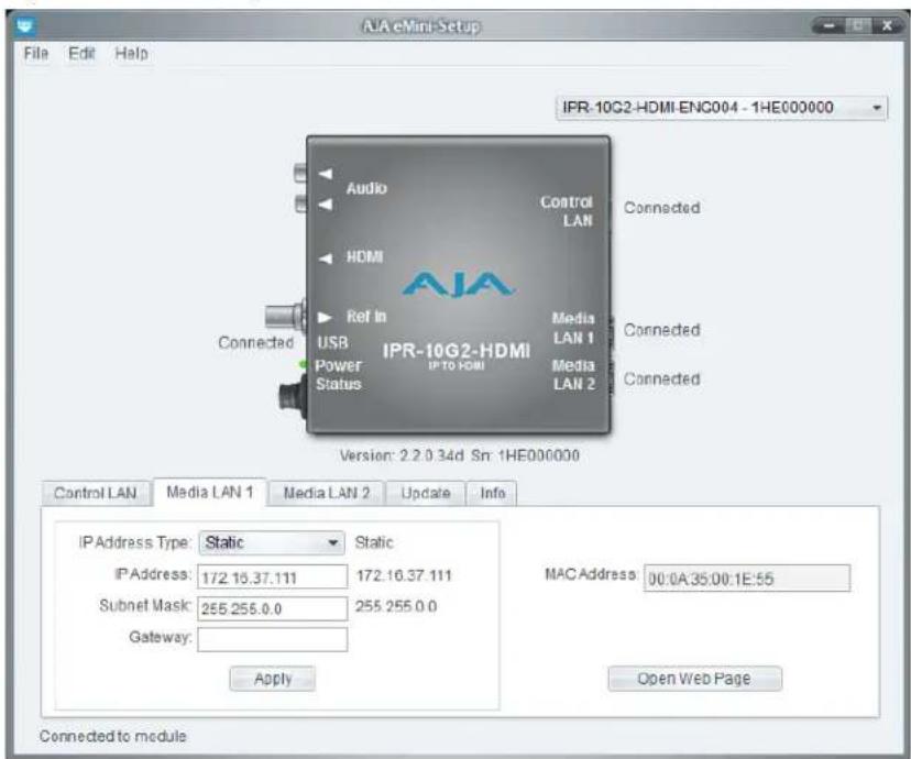
Use this Media LAN 1 tab to change the corresponding media network setup on the connected AJA device. You must click the Apply button to initiate any network configuration changes.
IP Address Type - Choose from DHCP or Static IP Address.
NOTE: If you intend to directly connect an IPT to an IPR, then you will need to use sequential static IP addresses for both units (Transmit and Receive).
IP Address - The current IP Address is displayed. A different IP address can be entered.
Subnet Mask - The current Subnet Mask is displayed. A different subnet mask can be entered.
Gateway - The current Gateway address is displayed. A different gateway address can be entered. On the Media LAN, the gateway may be left blank. (A gateway is required on the Control LAN).
MAC Address - This is the permanent MAC address of the Media LAN Ethernet port of the AJA device.
Open Web Page - Opens the IP Mini-Converter's web interface in a web browser.
Figure 19. eMini-Setup Media LAN 2 Tab Screen

Use this Media LAN 2 tab to change the corresponding media network setup on the connected AJA device. You must click the Apply button to initiate any network configuration changes.
IP Address Type - Choose from DHCP or Static IP Address.
NOTE: If you intend to directly connect an IPT to an IPR, then you will need to use sequential static IP addresses for both units (Transmit and Receive).
IP Address - The current IP Address is displayed. A different IP address can be entered.
Subnet Mask - The current Subnet Mask is displayed. A different subnet mask can be entered.
Gateway - The current Gateway address is displayed. A different gateway address can be entered. On the Media LAN, the gateway may be left blank. (A gateway is required on the Control LAN).
MAC Address - This is the permanent MAC address of the Media LAN Ethernet port of the AJA device.
Open Web Page - Opens the IP Mini-Converter's web interface in a web browser.
Update Tab Screen
Figure 20. eMini-Setup Update Tab Screen
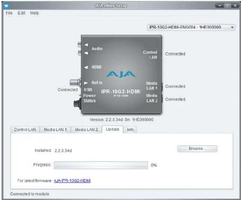
Use this Update tab to install new firmware.
Installed - This field shows the version of the firmware currently installed.
Browse - This button opens a navigation window, allowing you to select the firmware and load that version of firmware into the AJA device's non-volatile memory.
Progress - This indicator bar shows the progress of firmware installation.
Firmware Update Procedure
- Check the AJA website for new firmware.
- If new software is found, download it and uncompress the file archive (.zip).
- Connect the device to a Mac or PC via a USB port on the computer.
- Click the Update tab. Click the Browse button. Navigate to the firmware (.ajas extension), open it, and confirm the update. Progress will be shown via the "Progress" bar.
- After the update, the AJA device must be rebooted by clicking on the Reboot button in the prompt window.
See also: "Firmware Screen" on page 53 regarding the process of working with firmware with the IP Mini-Converter's Web UI.
Figure 21. eMini-Setup Info Tab Screen

This tab provides basic information about the connected AJA device. This information is mostly useful when calling AJA Support for service or technical support.
System Name - This field allows you to give your AJA device a unique name. This can be useful if you have several attached to a Mac/PC via USB so you can distinguish between them easily.
Type - This is the factory set model name of the AJA device.
Authentication - If Authentication has been Enabled on the web browser Access tab, you can disable the security feature by clicking the Disable button.
Chapter 3 – 10 GigE IP Mini-Converters Web Interface
Overview
Once you have established network connectivity with the 10 GigE IP MiniConverter, you can further configure and more fully control the unit through its web interface. Subsequently, eMini-Setup is no longer required to interface with the unit.
NOTE: It is often best to remove the USB connection once you have acquired the web interface. This prevents accidentally using eMini-Setup to change parameters already set via the web UI.
Remote Control Overview
An optimized web server in the 10 GigE IP Mini-Converter allows remote control and parameter setting adjustments via a browser client running on a network wired computer. The network can be a closed local area network, a direct connection between a 10 GigE IP Mini-Converter and a computer, or even exposed through a firewall to a WAN.
Each 10 GigE IP Mini-Converter uses a standard RJ-45 connector for the Control LAN connection, and two SFP+ cages for the 10 Gbps Ethernet Media LAN connections.
NOTE: Safari is the preferred web browser for control on the Mac, and additionally Chrome and Firefox on Windows. Other web browsers may work, but AJA cannot guarantee consistent operation for all web browsers or web browser versions.
To connect to the 10 GigE IP Mini-Converter, attach the unit to your network and enter its Control Network IP address into the web browser. If authentication has been configured, you may need to enter a password.
Networking Option – Using Only the Media LAN Port for Control and Media Settings
To reduce facility cabling to the 10 GigE IP Mini Converter, it is an option to setup your network connection through an Ethernet switch via the Media LAN ports (rather than using the dedicated Control Port). This means that you will have just one or two cables to the unit, instead of two or three.
To implement this approach, follow these general steps:
- Note the IP address of the unit's Media LAN 1 or Media LAN 2 port. This should be a static IP address.
- Connect the controlling computer's Ethernet port that is being used to control the unit into an Ethernet switch. This requires disconnecting the Ethernet cable from the Control LAN port of the unit.
- Connect the Media LAN port of the unit into the Ethernet switch.
- Connect the source of the Media IP stream into the Ethernet switch.
-
Set the controlling computer's Ethernet port that is being used to control the 10 GigE IP Mini-Converter to DHCP.
-
From the controlling computer, point a web browser to the IP address noted in step 1. The 10 GigE IP Mini-Converter's web user interface displays in the browser.
Web Browser via Ethernet
General Screen Information
All IP Mini-Converter web screens have certain areas and controls in common. Vertical and horizontal scroll bars appear when information extends past the border of a panel.
The round blue Up/Down arrow button on each panel and many status parameters opens and closes that pane or set of parameters.
Menu Panel
On the left of each screen is a Menu panel listing all the available screens. Click any of these links to jump to that screen.
Alarms Panel
Alarms are displayed in a panel on the left side of each screen. Clicking on the arrow opens or closes this panel to show or hide the alarms. Hovering the mouse over an alarm (red) or warning (yellow) may provide additional detail about the condition.
Connections Panel
On the right side of every screen is a Connection panel listing information for the connected IP Mini-Converter.
Network Panel
Also on the right is a Network pane that lists other IP Mini-Converters on the network. The gear icon opens the Network Screen, the same as selecting Network from the Menu Panel. Right-clicking on the name of an IP Mini-Converter in this list allows you to turn on the Identify feature, which will blink all four of the Ethernet LEDs of that device at a 1 second rate.
Parameters and Information
The rest of the screen displays all the parameter selections and information available for the selected IP Mini-Converter screen.
Figure 22. Overview of Web Browser User Interface

Dynamic Controls
- Hovering the mouse on a parameter name displays a brief description of its function.
- From the Config Screen, right clicking on the parameter name resets just that parameter to its factory default.
- For values with sliders, fine control is achieved using the arrow keys on the keyboard to move the slider the minimum amount. The numeric value can also be clicked on to enter a specific value.
Figure 23. IPT-10G2-SDI Status Screen 1 of 2
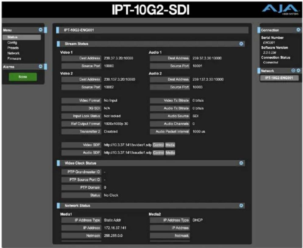
The IPT-10G2-SDI Status screen reports the current status and settings for:
- Stream Status
- Video Clock Status
- Network Status
- NMOS Status
- Firmware Status
Each group of parameters can be expanded or collapsed.
Link Layer Discovery Protocol (LLDP)
Under the Network Status area of the Status Screen, for network switches that support LLDP, the Chassis ID and the Port ID of the first switch encountered upstream in the path from the IP Mini-Converter device to the network will be displayed in the LLDP Chassis ID and LLDP Port ID fields.
That first upstream switch, in turn, displays the LLDP information (Chassis ID and Port ID) of the downstream IP Mini-Converter.
Figure 24. IPT-10G2-SDI Status Screen 2 of 2

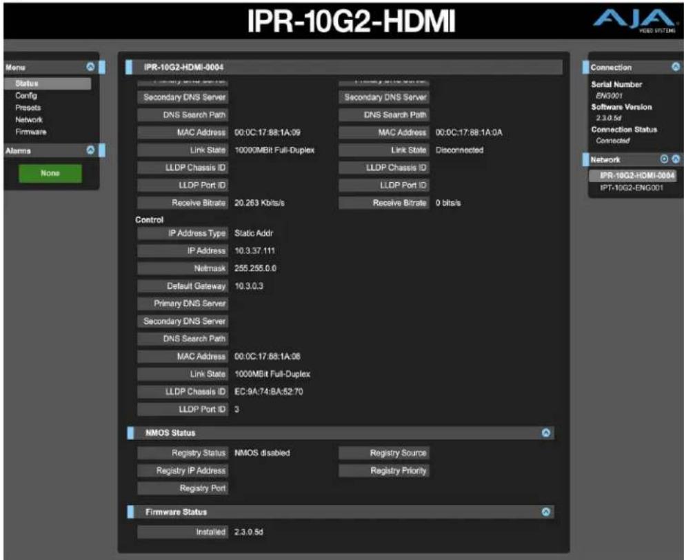
Figure 25. IPR-10G2-HDMI Status Screen 1 of 2

The IPR-10G2-HDMI Status screen reports the current status and settings for:
- Input Status
- Video Clock Status
- Network Status
- NMOS Status
- Firmware Status
Each group of parameters can be expanded or collapsed.
Link Layer Discovery Protocol (LLDP)
Under the Network Status area of the Status Screen, for network switches that support LLDP, the Chassis ID and the Port ID of the first switch encountered upstream in the path from the IP Mini-Converter device to the network will be displayed in the LLDP Chassis ID and LLDP Port ID fields.
That first upstream switch, in turn, displays the LLDP information (Chassis ID and Port ID) of the downstream IP Mini-Converter.
Figure 26. IPR-10G2-HDMI Status Screen 2 of 2
Config Screen
This section describes the Config Screen for the IPT-10G2-SDI followed by the Config Screen for the IPR-10G2-HDMI.
IPT-10G2-SDI
The IPT-10G2-SDI Config Screen, shown in three parts, has the parameters required for the general operation of the IPT-10G2 units.
Figure 27. IPT-10G2-SDI Config Screen 1 of 3
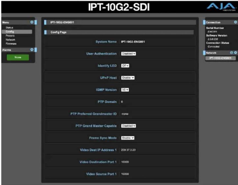
System Name
Defines a name for the system and gives it a unique identifier. This name is used when displaying systems through the web interface.
User Authentication
Enable or disable user password authentication for the web interface.
Identify LED
Enables flashing of the Ethernet LEDs on the unit.
UPnP Host
Enable or disable network discovery using Universal Plug and Play.
IGMP Version
Select the Internet Group Management Protocol Version. AJA supports IGMP v2 and v3.
NOTE: It is important to know which version of IGMP is in use on your network. Selecting the wrong IGMP version may cause long delays in processing multicast subscriptions. See your network engineer for more information.
PTP Domain
NOTE: Applicable only if PTP is selected for Video Output Clock Selection.
The PTP Domain field is for the ID of the PTP Source Port. While it is possible that there could be multiple PTP domains, most implementations will use "0". If unsure, consult with your network administrator. Possible values range from 0 to 127.
PTP Preferred Grandmaster ID
NOTE: Applicable only if PTP is selected for Video Output Clock Selection.
There can be multiple Grandmaster IDs. However, most of the time, it will be automatically determined. Typically, it is the same as the Ethernet address for the port of the Grandmaster.
Example of a PTP Grandmaster ID:
• 08-00-11-FF-FE-22-04-D6
PTP Grand Master Capable
NOTE: Applicable only if PTP is selected for Video Output Clock Selection.
For local demonstration purposes only, the IPT-10G2-SDI and IPT-10G2-HDMI can act as a grandmaster in network environments where there is not one already present, such as during basic testing, or setting up a PoC or demonstration.
CAUTION: Do not enable this control unless you have first checked with your network administrator.
Disable - Disables the PTP Grand Master capability.
Enable - Enables the PTP Grand Master capability.
Frame Sync Mode
Enabling Frame Sync Mode is recommended when you are using a source device that does not have a Reference Input (such as an HDMI camera, for example). A source device without a Reference Input cannot be locked to PTP before its signal arrives at the IPT-10G2-SDI and IPT-10G2-HDMI.
However, by enabling Frame Sync Mode, the incoming baseband video packets are conditioned by the Frame Sync and timed for the ST 2110 network, adding 1 to 2 frames of latency before being sent out.
Enable - Incoming baseband video packets are timed and sent out after being conditioned by the Frame Sync.
Bypass - Incoming baseband video packets bypass the Frame Sync.
NOTE: If your source device has a Reference Input, you do not need to enable Frame Sync Mode. Instead, you can lock to PTP by using the IPT-10G2-SDI's or IPT-10G2-HDMI's Reference Output. This provides the unit with the ability to lock cameras, tape decks, Ki-Pro, Kona, or other sources to PTP timing. See "Ref Output Format" on page 37 for details.
Video Dest IP Address 1
Enter the destination IP address of the video packets.
Video Destination Port 1
Enter the UDP destination port of the video packets.
Video Source Port 1
Enter the UDP source port of the video packets.
Figure 28. IPT-10G2-SDI Config Screen 2 of 3

Audio Dest IP Address 1
Enter the destination IP address of the audio packets.
Audio Destination Port 1
Enter the UDP destination port of the audio packets.
Audio Source Port 1
Enter the UDP source port of the audio packets.
Transmitter 2
Enable or disable transmitter 2.
Video Dest IP Address 2
Enter the destination IP address of the video packets.
Video Destination Port 2
Enter the UDP destination port of video packets.
Video Source Port 2
Enter the UDP source port of the video packets.
Audio Dest IP Address 2
Enter the destination IP address of the audio packets.
Audio Destination Port 2
Enter the UDP destination port of the audio packets.
Audio Source Port 2
Enter the UDP source port of the audio packets.
Ref Output Format
NOTE: The Ref Output Format control is displayed only when the Frame Sync Mode control is set to Bypass.
The IPT-10G2-SDI and IPT-10G2-HDMI generate an analog/tri-level reference output synchronized to the PTP clock in your facility. When converting baseband video to ST2110, connect your traditional video source to this reference output to lock it to the facility PTP timing prior to bringing it into the IPT-10G2-SDI or IPT-10G2-HDMI for conversion. This provides the unit with the ability to lock cameras, tape decks, Ki-Pro, Kona, or other sources to PTP timing.
Additionally, the IPT-10G2-SDI and IPT-10G2-HDMI can fulfill the function of a PTP to analog black/tri-level reference converter device, which some applications will require.
Select one of the following video reference output formats:
- NTSC 525i
• PAL 625i - 1280x720p 50
• 1280x720p 59.94 - 1280x720p 60
• 1920x1080i 48
• 1920x1080i 50
• 1920x1080i 59.94 - 1920x1080i 60
• 1920x1080p 23.98 - 1920x1080p 24
- 1920x1080p 25
• 1920x1080p 29.97 - 1920x1080p 30
Ref Output H Offset
NOTE: The Ref Output H Offset control is displayed only when the Frame Sync Mode control is set to Bypass.
Select the horizontal reference offset in pixels (range -2750 pixels to +2750 pixels). To set the value, use one of three methods:
- Click and drag the slider control, or
- Click the slider control to select it, then use the left/right or up/down arrow keys on your keyboard, or
- Click the pixels text to select it, then enter a numerical value using your keyboard.
Ref Output V Offset
NOTE: The Ref Output V Offset control is displayed only when the Frame Sync Mode control is set to Bypass.
Select the vertical reference offset in pixels (range -1125 lines to +1125 lines).
To set the value, use one of three methods:
- Click and drag the slider control, or
- Click the slider control to select it, then use the left/right or up/down arrow keys on your keyboard, or
- Click the lines text to select it, then enter a numerical value using your keyboard.
Figure 29. IPT-10G2-SDI Config Screen 3 of 3
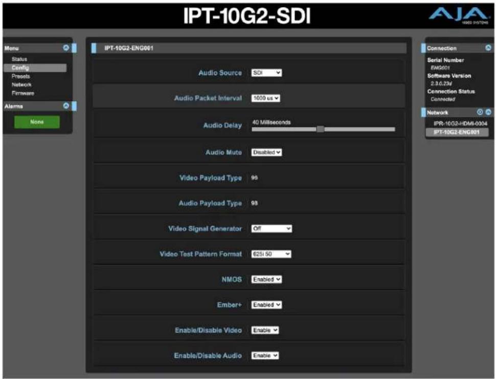
Audio Source
Select one of the following audio sources:
• SDI
- Analog
- Disabled
Audio Delay
Use the Audio Delay control as needed to synchronize audio and video signals. Select a fixed number of milliseconds to delay audio output by relative to the video.
0 to 85 Milliseconds - To set the value of the audio delay setting, use one of three methods:
- Click and drag the slider control, or
- Click the slider control to select it, then use the left/right or up/down arrow keys on your keyboard, or
- Click the Milliseconds text to select it, then enter a numerical value using your keyboard.
Audio Mute
Enable or disable audio mute.
Video Payload Type
Enter a value to specify the video payload type.
Audio Payload Type
Enter a value to specify the audio payload type.
Video Signal Generator
You can output a test video signal to validate video signal connections. Select Off or Test Pattern.
Off - No video signal is generated.
Other choices
- 100% Bars
- 75% Bars
- Ramp
- Multi Burst
- Line Sweep
- Check Field
- Flat Field
- Multi Pattern
- Black
- White
- Linear Ramp
- Slant Ramp
Test Pattern - Color bars with a moving gray line are generated in the currently selected video format and sent to the Video Output.
NOTE: The Test Pattern is supported only in 1080p and 1080i formats.
Video Test Pattern Format
Determines the video format output from the system's internal test signal generator. Select from the following options:
• 525i 59.94
• 625i 50
• 720p 50, 59.94, 50, 59.94
• 1080p 23.98, 24, 25, 29.97, 30, 50, 59.94, 60
NMOS
Enable or disable network discovery for the device.
NMOS uses the address of the unit's internal web server for communications. When the unit boots up, it actively scans the network for an NMOS registry using MDNS/DNS. If it finds one, it tells the NMOS registry what it is and what its capabilities are.
If the unit does not find an NMOS registry, it continues to announce itself through MDNS so that it can be discovered. Once discovered, it registers itself with whatever has discovered the unit through MDNS.
Ember+
Enable or disable Ember+ network discovery for the device.
Enable/Disable Video
Enable or disable video for the device.
Enable/Disable Audio
Enable or disable audio for the device.
IPR-10G2-HDMI
The IPR-10G2-HDMI Config Screen, shown in three parts, has the parameters required for the general operation of the IPR-10G2 units.
Figure 30. IPR-10G2-HDMI Config Screen 1 of 3

System Name
Defines a name for the system and gives it a unique identifier. This name is used when displaying systems through the web interface.
User Authentication
Enable or disable user password authentication for the web interface.
Identify LED
Enables flashing of the Ethernet LEDs on the unit.
UPnP Host
Enable or disable network discovery using Universal Plug and Play.
IGMP Version
Select the Internet Group Management Protocol Version. AJA supports IGMP v2 and v3.
NOTE: It is important to know which version of IGMP is in use on your network. Selecting the wrong IGMP version may cause long delays in processing multicast subscriptions. See your network engineer for more information.
System Modes
There is a set of pre-built system configuration modes, or "system modes," available from the System Mode control on the Config page of the IPR-10G2 web UI. These pre-built System Modes are designed to save you time so that you can get your unit up and running quickly.
NOTE: The System Modes are available only for the IPR-10G2-SDI and IPR-10G2-HDMI units; they are not needed on the IPT-10G2-SDI and IPT-10G2-HDMI units since the transmitter's functionality is simpler.
Each System Mode is built for a specific type of use case, taking into account factors such as network conditions, protection requirements, timing, and latency considerations.
NOTE: The choice of System Mode will impact which controls are available. Multiple variations of controls are possible on the Config page.
The following tables present the core characteristics for each pre-built System Mode.
Table 1. PTP Low Latency System Mode characteristics
| System Mode 1 PTP Low Latency | |
| Description PTP environment | Lowest protection*Near-zero latency** |
| Video Clock Mode PTP | |
| Packet Protection Mode Bypass | |
| Frame Sync Mode Bypass | |
| Audio Sample Rate Converter Bypass | |
| Transmitter Requirements Narrow transmitter only | |
| Latency Expected 0 frames (~4 video lines) | |
Table 2. PTP Protected System Mode characteristics
| System Mode 2 PTP Protected | |
| Description PTP environment | Greatest protection*Maximum latency** |
| Video Clock Mode PTP | |
| Packet Protection Mode Enabled | |
| Frame Sync Mode Enabled | |
| Audio Sample Rate Converter Bypass | |
| Transmitter Requirements Can accept wide transmitter | |
| Latency Expected Packet protection window size +2 frames |
Table 3. Gateway System Mode characteristics
| System Mode 3 Gateway | |
| Description Gateway environment | No packet protection*Medium latency** |
| Video Clock Mode Ref In | |
| Packet Protection Mode Bypass | |
| Frame Sync Mode Enabled | |
| Audio Sample Rate Converter Enabled | |
| Transmitter Requirements Can accept wide transmitter | |
| Latency Expected 2 frames |
Table 4. Gateway Protected System Mode characteristics
| System Mode 4 Gateway Protected | |
| Description Gateway environment | Greatest protection*Maximum latency** |
| Video Clock Mode Ref In | |
| Packet Protection Mode Enabled | |
| Frame Sync Mode Enabled | |
| Audio Sample Rate Converter Enabled | |
| Transmitter Requirements Can accept wide transmitter | |
| Latency Expected Packet protection window size +2 frames | |
Table 5. Asynchronous System Mode characteristics
| System Mode 5 Asynchronous | |
| Description Setup/demo/troubleshooting environmentNo packet protectionLow latency** | |
| Video Clock Mode Video In | |
| Packet Protection Mode Bypass | |
| Frame Sync Mode Enabled | |
| Audio Sample Rate Converter Enabled | |
| Transmitter Requirements Can accept wide transmitter | |
| Latency Expected 2 frames | |
*Protection against loss or degradation of picture. Low protection does not necessarily mean picture loss or degradation will result, as this would depend on the network architecture and numerous other factors.
**The term latency is referring to latency on the network. The network in this context refers to the IP Mini Converters end-to-end — from video into IP Transmitter to video out of IP Receiver, including IP switches along the way.
Unlike the five pre-built System Modes just described, each of which are "safe," the Advanced Mode, described below, does not guard against a user applying contradictory settings that could provide unpredictable results.
NOTE: When working with Advanced Mode, if the configuration settings become problematic, you can always "revert" to one of the five pre-built System Modes to get the unit running again with established internally compatible settings.
Table 6. Advanced System Mode characteristics
| System Mode 6 Advanced | |
| Description User defined | |
| Video Clock Mode User defined | |
| Packet Protection Mode User defined | |
| Frame Sync Mode User defined | |
| Audio Sample Rate Converter User defined | |
| Transmitter Requirements Based on user selections | |
| Latency Expected Based on user selections |
Video Clock Mode
Select which clock source you want to use for the video output. The clock selection determines whether or not you need to use the Frame Sync in order to have glitch-free output.
PTP - PTP is recommended. Ideally, both the IPR-10G2 and the video source would use PTP.
Video In - Use the input signal as the clock source. If you do not have PTP available, Lock to Input is the next recommended choice and it allows for a glitch-free video output.
Freerun - Selecting Free Run requires that you use Frame Sync in order to prevent output glitches.
Ref In - If the Reference In source is synchronized with the Grand Master PTP, you will not need to use the Frame Sync. On the other hand, if the Reference In is unrelated to the PTP, such as if it is from an independent sync generator, you will need to use Frame Sync in order to prevent output glitches. New Reference Input support for IPR-10G2-HDMI and IPR-10G2-SDI provides users with the ability to lock the local baseband output to the timing of the baseband environment at the destination.
PTP Domain
NOTE: Applicable only if PTP is selected for Video Output Clock Selection.
Select the PTP domain from values ranging from 0 to 127. This should match the PTP domain configured on the PTP Grandmaster clock on the network.
PTP Preferred Grandmaster ID
NOTE: Applicable only if PTP is selected for Video Output Clock Selection.
In most situations, this field should left blank.
If multiple PTP Grandmasters are present on the same domain on the network, the device will automatically select a PTP Grandmaster to lock to. However, if you prefer a specific PTP Grandmaster, then set this field to the ID of the preferred Grandmaster.
Example of a PTP Grandmaster ID:
• 08-00-11-FF-FE-22-04-D6
PTP Grand Master Capable
NOTE: Applicable only if PTP is selected for Video Output Clock Selection.
For local demonstration purposes only, the IPR-10G2-HDMI and IPR-10G2-SDI can act as a grandmaster in network environments where there is not one already present, such as during basic testing, setting up a PoC or demonstration.
CAUTION: Do not enable this control unless you have first checked with your network administrator.
Disable - Disables the PTP Grand Master capability.
Enable - Enables the PTP Grand Master capability.
Packet Buffer Window Size (ms)
Window size in milliseconds for packet buffering.
Packet Protection Mode
With Packet Protection Mode, the IPR-10G2 will accept signals from both Media LAN 1 and Media LAN 2, allowing for hitless media switching in the event that one of the signals is interrupted.
Single Stream - When set to Single Sream, the IPR-10G2 will accept one signal from Media LAN 1 only. If packets are out of order, they will be rearranged into the correct order. Note that hitless protection is not part of Single Stream mode.
Dual Stream - When set to Dual Stream, hitless media protection is enabled. Two identical copies of the same stream are accepted from Media LAN 1 and Media LAN 2. Both streams are compared packet by packet. If one stream is missing a packet, it will be taken from the other stream to make sure that one good stream comes through properly.
Bypass - When set to Bypass, the IPR-10G2 takes the media stream from Media LAN 1. The stream bypasses the entire hitless protection block.
Hitless Window Size (ms)
NOTE: Applicable only if Hitless Media Support is enabled.
Set the amount of time in milliseconds that the unit will look for redundant packets to decide to accept or reject them for hitless media switching.
To determine the hitless window size, consider any delay between the signals, expected jitter, along with any other sources of potential delay between signals.
Possible values range from 1 to 50. The actual range is determined by the signal's frame rate, raster size and other factors.
Frame Sync Mode
Frame Sync Mode can be enabled for synchronizing frames to the timing source you are using.
Enable - Frame Sync Mode is enabled.
Bypass - Frame Sync Mode is disabled.
Audio Rate Converter Mode
In cases where there are either missing audio packets or the audio clock is not synchronous with the timing source, the audio rate converter can match the output audio rate to the local clock. Select either of the following options:
- Use Audio Src
- Bypass Audio Src
Figure 31. IPR-10G2-HDMI Config Screen 2 of 3
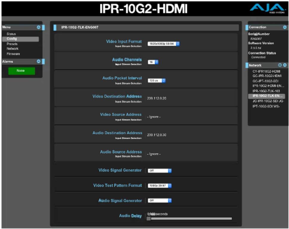
Input Stream Selection
Select SDP, Manual or NMOS/Ember.
SDP - The SDP method greatly simplifies the configuration process for the Input Stream Selection fields. Selecting SDP causes the following four fields to display:
- SDP URL Video - Enter the SDP URL Video string. For example: http://172.16.0.109/txch2v.sdp
- SDP URL Audio - Enter the SDP URL Audio string. For example: http://172.16.0.109/bxch2a1.sdp
- SDP URL Video 2 - Enter the SDP URL Video string. For example: http://172.16.0.109/txch2v.sdp
- SDP URL Audio 2 - Enter the SDP URL Audio string. For example: http://172.16.0.109/txch2a1.sdp
The strings entered into the SDP URL Video and SDP URL Audio fields point to SDP files that are created by the source that is transmitting the video signal.
The SDP files contain all required configuration parameters for the following Input Stream Selection fields:
- Video Input Format
- Audio Channels
• Audio Packet Interval
• Video Destination Address
• Video Source Address
• Audio Destination Address
• Audio Source Address.
• Video 2 Destination Address
• Video 2 Source Address
• Audio 2 Destination Address
• Audio 2 Source Address
Manual - When Manual is selected, you must enter configuration parameters manually into the following Input Stream Selection fields:
- Video Input Format
- Audio Channels
- Audio Packet Interval — Select the time interval between packets transmitted by the audio transmitter. The receivers support audio packet intervals of 1 millisecond or 125 microseconds.
- Video Destination Address — The IP address corresponding to where the video stream is being sent. In multicast mode, this is the multicast IP address of the ST 2110 stream. In unicast mode, this is the unicast IP address of the media port on the receiver. The Video Destination Address is almost always required on a receiver (IPR-10G2-HDMI, IPR-10G2-SDI). Additionally, the destination UDP port of the stream may also be specified by appending it with a colon to the destination address.
• For example: 239.0.0.1:10000
- Video Source Address — The unicast IP address of the media port on the sending device, such as an IPT-10G2-HDMI or IPT-10G2-SDI. This field should be left blank in most situations. It is useful only in setups where multiple transmitters are transmitting to the same multicast destination address and IGMPv3 is in use to subscribe to the stream from a specific source.
- Audio Destination Address — This is the audio stream equivalent of the Video Destination Address.
- Audio Source Address — This is the audio stream equivalent of the Video Source Address.
• Video 2 Destination Address
• Video 2 Source Address
• Audio 2 Destination Address
• Audio 2 Source Address
NMOS/Ember - When NMOS/Ember is selected, input stream selection occurs through network discovery and communication with facility automation.
NMOS uses the address of the unit's internal web server for communications. When the unit boots up, it actively scans the network for an NMOS registry using MDNS/DNS. If it finds one, it tells the NMOS registry what it is and what its capabilities are.
If the unit does not find an NMOS registry, it continues to announce itself through MDNS so that it can be discovered. Once discovered, it registers itself with whatever has discovered the unit through MDNS.
Figure 32. IPR-10G2-HDMI Config Screen 3 of 3
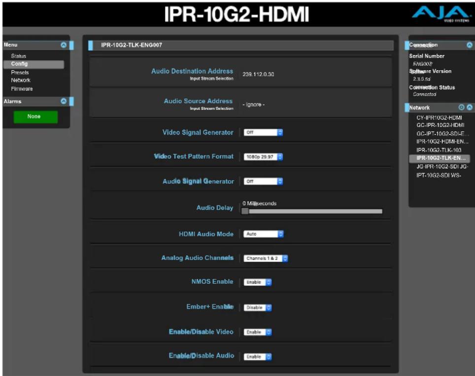
Video Signal Generator
You can output a test video signal to validate video signal connections. Select Off or Test Pattern.
Off - No video signal is generated.
Other choices
- 100% Bars
- 75% Bars
- Ramp
- Multi Burst
- Line Sweep
- Check Field
- Flat Field
- Multi Pattern
- Black
- White
- Linear Ramp
- Slant Ramp
Test Pattern - Color bars with a moving gray line are generated in the currently selected video format and sent to the Video Output.
NOTE: The Test Pattern is supported only in 1080p and 1080i formats.
Video Test Pattern Format
Determines the video format output from the system's internal test signal generator. Select from the following options:
• 525i 59.94
• 625i 50
• 720p 50, 59.94, 50, 59.94
• 1080p 23.98, 24, 25, 29.97, 30, 50, 59.94, 60
Audio Signal Generator
You can output a test audio signal to validate audio signal connections. Select Off or 400 Hz Tone.
Off - No audio signal is generated.
400 Hz Tone - A 400 Hz tone is generated on both channels of a pair and sent to the analog RCA audio outputs. Each channel pair is at a different volume. Channel pair 1/2 is the loudest. Channel pair 7/8 is the softest.
Audio Delay
Use the Audio Delay control as needed to synchronize audio and video signals.
0 to 100 Milliseconds - Use the slider control with a mouse or the right and left arrow keys on your keyboard to adjust the audio delay setting.
HDMI Audio Mode
Determine how you want the HDMI audio to function. It can auto-detect which channels are carrying the audio (either Channels 1-2 or Channels 1-8), or you can manually select which channels will carry audio. Select one of the following:
- Auto
- Channels 1-2
- Channels 1-8
Analog Audio Channels
Select which pair of analog audio channels you want to go out through the analog RCA audio outputs. Choose one of the following:
- Channels 1 & 2
- Channels 3 & 4
- Channels 5 & 6
- Channels 7 & 8
NMOS Enable
Enable or disable network discovery for the device.
NMOS uses the address of the unit's internal web server for communications. When the unit boots up, it actively scans the network for an NMOS registry using MDNS/DNS. If it finds one, it tells the NMOS registry what it is and what its capabilities are.
If the unit does not find an NMOS registry, it continues to announce itself through MDNS so that it can be discovered. Once discovered, it registers itself with whatever has discovered the unit through MDNS.
Ember+ Enable
Enable or disable network discovery for the device.
Enable/Disable Video
Enable or disable video for the device.
Enable/Disable Audio
Enable or disable audio for the device.
Presets Screen
Figure 33. IPR-10G2-HDMI Presets Screen

The Presets screen allows you to save Preset Configurations into 20 separate memory registers and recall the presets whenever needed.
The Presets screen also includes Export and Import functions that allow exporting one or all presets to your computer as files and importing exported preset files from your computer. A displayed message indicates successful or failed saves, recalls, exports, and imports.
Presets Screen Controls
Factory Reset - Factory Reset recalls all editable parameters to their factory default settings. Individual presets and Network settings, such as the IP Addresses, are not affected.
Recall - The Recall buttons recall the saved preset configurations.
CAUTION: When you recall a Preset Configuration, the recalled preset immediately replaces the system's existing configuration. All previous settings are lost unless you have previously stored them in another preset configuration or an exported file.
Save - The Save buttons let you save the current configuration into the preset register with the associated name and number. A preset is a set of all parameters as they were set at the time the preset was saved. Only editable parameters are saved in the presets. Non-editable parameters are not saved.
To change a preset name, click in the name's text field, type a new name, and press Enter to save the name. After entering text, you can click the mouse outside of the edit box to exit without changing the name.
CAUTION: IP Mini-Converter stored presets may contain a web server access password. If you share an exported preset to someone, that person can extract the password. Before loaning the device to someone, or returning it as a rental, it is recommended that you clear the device of sensitive information.
Export - The Export buttons save the associated preset contents to a file on your computer. The file gets exported to the default download location specified in your browser options. The file name is the same as the preset name with the suffix .presets. If you export multiple files for the same preset, a number gets appended to ensure a unique file name. The file size is small, usually less than 100 kilobytes.
Import - The Import buttons let you browse for and import a preset file on your computer into the preset register associated with the selected button. A dialog box warns you that the operation will overwrite the current preset contents with the file contents. You can only import presets from an IP MiniConverter.
Erase - The Erase buttons erase the data in that preset.
Export Presets 1–20 (All) - Export All lets you save the contents of all presets to a file on your computer.
The file gets exported to the default download location specified in your browser options with the name all.presets. If you export multiple files, a number gets appended to ensure a unique file name.
Import Presets 1–20 (All) - Import All lets you browse for and import a previously exported all.presets file from your computer. A dialog box warns you that the operation will overwrite all 20 current preset contents with the contents stored in the file.
Erase Presets 1–20 (All) - Erase All erases all data from all the presets. A dialog box warns you that the operation will erase all 20 current presets.
USB Keyboard Control
The USB Keyboard Control, used for quickly recalling previously created device presets, is available for the IPR-10G2-SDI and IPR-10G2-HDMI.
Connect a standard USB keyboard with the USB port of the IPR-10G2 device. You can recall presets 1 through 20 by using keyboard numbers 1 through 9 to access presets 1 through 9, then keyboard letters A through K to access presets 10 through 20.
IMPORTANT: Using the Keyboard Number 0 (zero) will initiate a Factory Reset for the device.
Network Screen
Use the Network Configuration Control Tab to configure or modify settings for the Control LAN Ethernet port.
Figure 34. IPR-10G2-HDMI Network Configuration Control Tab
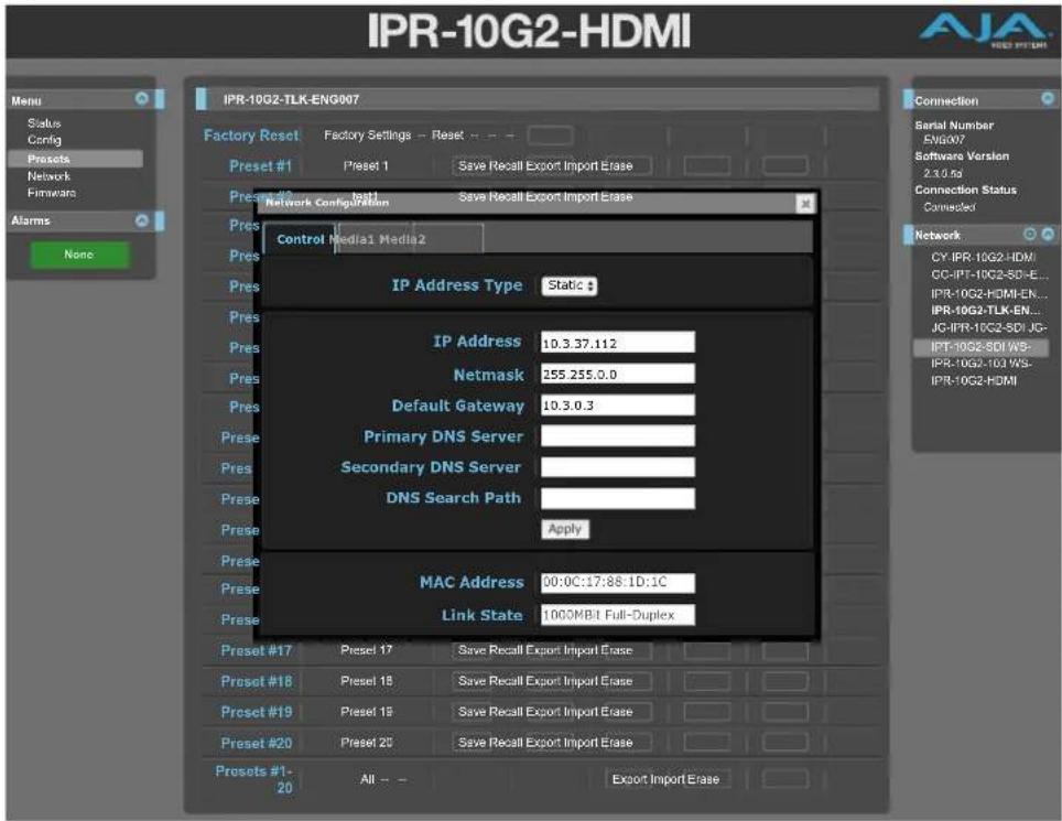
Use the Network Configuration Media 1 Tab to configure or modify settings for the Media 1 SFP+ cage for 10 Gbps Ethernet port.
Figure 35. IPR-10G2-HDMI Network Configuration Media 1 Tab

Use the Network Configuration Media 2 Tab to configure or modify settings for the Media 2 SFP+ cage for 10 Gbps Ethernet port.
Figure 36. IPR-10G2-HDMI Network Configuration Media 2 Tab

The Network screen allows you to view and change your IP Mini-Converter's network settings. Click Apply to activate any changes.
IP Address Type - IP Address Type determines the type of TCP/IP network configuration to be used. DHCP enables connecting to the network DHCP server, which assigns the IP Address, Netmask, and Gateway automatically. Static lets you set these parameters manually.
NOTE: If the IP Address Type is DHCP, the IP Address, Netmask, and Default Gateway are gray, indicating they are set automatically and cannot be changed unless IP Address Type is first set to Static. Changes are saved and activated upon confirmation using the Apply button.
- DHCP (default) - Selects automatic IP address assignment from the LAN DHCP server. If a DHCP server cannot be found, it fails over to the static IP address.
- Static - Assigns a static IP address manually. The factory default static IP address: 192.168.0.1.
IP Address - IP Address determines a static IP address to be used for TCP/IP networking. Consult your network administrator about how to set this value.
- If IP Address Type is set to DHCP, the IP address is set automatically by the network DHCP server and cannot be entered here.
- If IP Address Type is set to Static, enter an IP address compatible with your LAN here. Also enter a netmask and default gateway address in the following two parameters. Click Apply when you are ready to apply all three entries.
- If IP Address Type is set to DHCP and there is a DHCP failure, the IP address is set to the static IP address.
Netmask - Netmask determines the subnet mask to be used for TCP/IP networking.
- Enter a subnet mask compatible with your LAN. This is only needed for Static IP configurations. The factory default Subnet Mask is 255.255.255.0
- If IP Address Type is set to DHCP, the Subnet Mask is set by the DHCP server and cannot be changed by the user.
Default Gateway - Default Gateway determines the gateway or router used on your LAN for TCP/IP networking.
Without a properly configured default gateway (whether you have a router/gateway or not), your IP Mini-Converter will be unable to see other IP Mini-Converters on the network, although you may still be able to control this IP Mini-Converter via a web browser. Also, without a proper gateway defined, the discovery feature on the Network web page will not list other units on the network.
- Enter a default gateway or router address. This is only needed for Static IP configurations. The factory Default Gateway is 192.168.0.1.
- If IP Address Type is set to DHCP, the Default Gateway is set by the DHCP server and cannot be changed by the user.
MAC Address - Reports the connected IP Mini-Converter's Media Access Control Address.
Link State - Reports the current status of the Ethernet connection.
Firmware Screen
Figure 37. IPR-10G2-HDMI Firmware Screen

Downloading and Installing Updated Firmware
The Update Firmware screen allows you to download and install a firmware update from AJA.
To Download and Install Updated Firmware
- Visit the AJA website (aja.com) to locate and download the updated software. The following page provides support information and will include links to locations where you can download updates: https://www.aja.com/family/ip-converters#support
- After downloading the software update to your local drive, use the Browse or Choose File button to locate the local software copy.
- Follow the prompts to load the new firmware into your unit.
- After the firmware has finished installing, reboot the unit by disconnecting power for a few seconds, then reconnecting power.
NOTE: You can also update the firmware using eMini-Setup. See "Firmware Update Procedure" on page 25 for details.
Booting the 10 GigE IP Mini-Converters from the Safeboot Firmware
The 10 GigE IP Mini-Converters contain primary firmware and safeboot (secondary) firmware. To boot from the primary firmware, just cycle the unit's power.
In the event that the primary firmware becomes corrupted, you can boot the unit using the safeboot firmware.
To Boot from the Safeboot Firmware
- Remove power from the device.
- Using a very narrow tool, such as the end of a paper clip, press down and hold the recessed safeboot button, making sure you feel the button depress. The recessed safeboot button is located next to the Control LAN port.
Figure 38. Location of recessed safeboot button
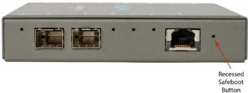
- While keeping the safeboot button depressed, apply power, then continue holding down the safeboot button for three seconds.
- Remove the paper clip from the safeboot button. The unit will boot from the safeboot firmware. After rebooting, the message "Safeboot" displays under the Alarms heading.
Figure 39. The Safeboot alarm message
- Finally, update the firmware as described above under "Downloading and Installing Updated Firmware" on page 53.
Following a successful firmware update and reboot, the message "None" displays under the Alarms heading.
Figure 40. The alarm message after a successful firmware update

IPT-10G2-SDI Tech Specs
Video Formats
• (HD) 1920x1080p 23.98, 24, 25, 29.97, 30, 50, 59.94, 60
• (HD) 1920x1080i 50, 59.94
• (HD) 1280x720p 50, 59.94, 60
• (SD) 625i 50
• (SD) 525i 59.94
Video Quality
• 10-bit, 4:2:2, uncompressed
Discovery, Registration and Control
- NMOS discovery and control according to standards IS-04 v1.3 and IS-05 v1.1
- Ember+ control (no discovery, control only)
- AJA REST API control (discovery via SSDP or MDNS)
- LLDP (Link Layer Discovery Protocol)
- Supported over dedicated management Ethernet port and in-band over media ports
Media Transport Interfaces
• SMPTE ST 2110 (-10, -20, -21, -30)
• 2x SFP+ Cages - SFPs not included
- Recommended 10 GigE SFP+ modules:
- Arista Networks SFP-10G-SR Compatible 10GBASE-SR
• Fiberstore SFP-10GSR-85 10G SFP+ 850nm
- Finisar FTLX1471D3BCL (for single mode 1310nm)
- Mellanox MFM1T02A-SR 850nm 10G
Note: Maximum supported SFP+ power is 500 mW per SFP+ cage
Video Input Digital
- 1x 3G SDI BNC (single source, with loop through)
- Up to 1080 60p, 4:2:2, 10-bits/pixel, YCbCr
Audio Input Digital
- Up to 16-channel, SDI embedded audio, 24-bit per channel, 48 kHz synchronous
Audio Input Analog
- 2x RCA analog audio
• Levels at -10 dBu (nominal) - Can only select audio channels 1-8
Video Output IP
- SMPTE ST 2110
- Single video channel output
- SMPTE ST 2022-7 dual stream output for hitless switching
• Tx support for Narrow, Gapped Mode
Audio Output IP
- SMPTE ST 2110
- Up to 16-channels audio, 24-bit per channel, 48 kHz synchronous
• 1 ms or 125 μs packet interval
Reference
- 1x BNC
- Reference Out connector generates an analog/tri-level reference output synchronized to the PTP clock
- Used to lock baseband sources/devices to PTP, so video arriving at the IP transmitter is properly timed
IP Clock
- PTP support compliant with PTP PTPv2 / IEEE 1588-2008
• SMPTE ST 2059-1 compliant
User Interface
• 1x RJ-45 for 10/100/1000 Base-T Ethernet
- Web and REST clients supported for remote network setup and configuration
• 1x USB 2.0 Mini-B connector
- AJA eMini-Setup supported for network setup and configuration via local desktop computer
- Web and REST configuration is also supported in-band over media ports
Size (w x d x h)
- 5.07" x 0.94" x 5.06" (128.8 x 23.9 x 128.4 mm)
Weight
• 0.6 lb (0.3 kg)
Power
- 5-20 VDC Regulated, 13 Watts, Power supply required (DWP-U-R1 included with purchase)
Environment
- Safe Operating Temperature: 0 to 40 C (32 to 104 F)
- Safe Storage Temperature (Power OFF): -40 to 60 C (-40 to 140 F)
- Operating Relative Humidity: 10-90% noncondensing
- Operating Altitude: <3,000 meters (<10,000 feet)
IPT-10G2-HDMI Tech Specs
Video Formats
• (HD) 1920x1080p 23.98, 24, 25, 29.97, 30, 50, 59.94, 60
• (HD) 1920x1080i 50, 59.94
• (HD) 1280x720p 50, 59.94, 60
• (SD) 625i 50
• (SD) 525i 59.94
Video Quality
• 10-bit, 4:2:2, uncompressed
Discovery, Registration and Control
• NMOS discovery and control according to standards IS-04 v1.3 and IS-05 v1.1
- Ember+ control (no discovery, control only)
- AJA REST API control (discovery via SSDP or MDNS)
• LLDP (Link Layer Discovery Protocol)
- Supported over dedicated management Ethernet port and in-band over media ports
Media Transport Interfaces
• SMPTE ST 2110 (-10, -20, -21, -30)
• 2x SFP+ Cages - SFPs not included
- Recommended 10 GigE SFP+ modules:
• Arista Networks SFP-10G-SR Compatible 10GBASE-SR
• Fiberstore SFP-10GSR-85 10G SFP+ 850nm
• Finisar FTLX1471D3BCL (for single mode 1310nm)
• Mellanox MFM1T02A-SR 850nm 10G
Note: Maximum supported SFP+ power is 500 mW per SFP+ cage
Video Input Digital
• 1x HDMI Standard Type A connector
• HDMI v1.4b 24/30-bits per pixel
- Up to 1080 60p, 4:2:2, 10-bit, YCbCr/RGB
Audio Input Digital
- Up to 8-channel, HDMI embedded audio, 24-bit per channel, 48 kHz synchronous
Audio Input Analog
- 2x RCA analog audio
• Levels at -10 dBu (nominal) - Can only select audio channels 1-8
Video Output IP
- SMPTE ST 2110
- Single video channel output
- SMPTE ST 2022-7 dual stream output for hitless switching
• Tx support for Narrow, Gapped Mode
Audio Output IP
- SMPTE ST 2110
- Up to 8-channels audio, 24-bit per channel, 48 kHz synchronous
• 1 ms or 125 μs packet interval
Reference
- 1x BNC
- Reference Out connector generates an analog/tri-level reference output synchronized to the PTP clock
- Used to lock baseband sources/devices to PTP, so video arriving at the IP transmitter is properly timed
IP Clock
- PTP support compliant with PTP PTPv2 / IEEE 1588-2008
• SMPTE ST 2059-1 compliant
User Interface
• 1x RJ-45 for 10/100/1000 Base-T Ethernet
- Web and REST clients supported for remote network setup and configuration
• 1x USB 2.0 Mini-B connector
- AJA eMini-Setup supported for network setup and configuration via local desktop computer
- Web and REST configuration is also supported in-band over media ports
Size (w x d x h)
- 5.07" x 0.94" x 5.06" (128.8 x 23.9 x 128.4 mm)
Weight
• 0.6 lb (0.3 kg)
Power
- 5-20 VDC Regulated, 13 Watts, Power supply required (DWP-U-R1 included with purchase)
Environment
- Safe Operating Temperature: 0 to 40 C (32 to 104 F)
- Safe Storage Temperature (Power OFF): -40 to 60 C (-40 to 140 F)
- Operating Relative Humidity: 10-90% noncondensing
- Operating Altitude: <3,000 meters (<10,000 feet)
IPR-10G2-SDI Tech Specs
Video Formats
• (2K) 2048x1080p 23.98, 24, 25, 29.97, 30, 50, 59.94, 60
• (HD) 1920x1080p 23.98, 24, 25, 29.97, 30, 50, 59.94, 60
• (HD) 1920x1080i 50, 59.94
• (HD) 1280x720p 50, 59.94, 60
• (SD) 625i 50
• (SD) 525i 59.94
Video Quality
- Up to 2K 60p, 4:2:2, 8-bit, YCbCr uncompressed
• 4:2:2, 10-bit, YCbCr uncompressed
Discovery, Registration and Control
- NMOS discovery and control according to standards IS-04 v1.3 and IS-05 v1.1
- Ember+ control (no discovery, control only)
- AJA REST API control (discovery via SSDP or MDNS)
• LLDP (Link Layer Discovery Protocol) - Supported over dedicated management Ethernet port and in-band over media ports
Media Transport Interfaces
• SMPTE ST 2110 (-10, -20, -21, -30)
• 2x SFP+ Cages - SFPs not included
- Recommended 10 GigE SFP+ modules:
- Arista Networks SFP-10G-SR Compatible 10GBASE-SR
• Fiberstore SFP-10GSR-85 10G SFP+ 850nm
• Finisar FTLX1471D3BCL (for single mode 1310nm)
• Mellanox MFM1T02A-SR 850nm 10G
Note: Maximum supported SFP+ power is 500 mW per SFP+ cage
Video Input IP
- SMPTE ST 2110
- Single channel video input
- SMPTE ST 2022-7 dual stream input for hitless switching
- Rx support for Narrow/Wide, Gapped/Linear Modes
Audio Input IP
- SMPTE ST 2110
- Up to 16-channels audio, 24-bit per channel, 48 kHz synchronous
• 1 ms or 125 μs packet interval
Video Output Digital
• 2x 3G SDI BNC (single source, mirrored output)
• Frame syncing to facility clock
- Concealment of errors due to packet loss
Audio Output Digital
- Up to 16-channel, SDI embedded audio, 24-bit per channel, 48 kHz synchronous
Audio Output Analog
• 2x RCA analog audio
• Levels at -10 dBu (nominal)
- Can only select audio channels 1-8
Reference
- 1x BNC
• Analog/tri-level reference input
- Allows baseband output of IPR-10G2-SDI to be locked to the facility baseband clock
IP Clock
- PTP support compliant with PTP PTPv2, PTPv3 / IEEE 1588-2008
• SMPTE ST 2059-1 compliant
User Interface
• 1x RJ-45 for 10/100/1000 Base-T Ethernet
- Web and REST clients supported for remote network setup and configuration
• 1x USB 2.0 Mini-B connector
- AJA eMini-Setup supported for network setup and configuration via local desktop computer
- Web and REST configuration is also supported in-band over media ports
Size (w x d x h)
- 5.07" x 0.94" x 5.06" (128.8 x 23.9 x 128.4 mm)
Weight
• 0.6 lb (0.3 kg)
Power
- 5-20 VDC Regulated, 13 Watts, Power supply required (DWP-U-R1 included with purchase)
Environment
- Safe Operating Temperature: 0 to 40 C (32 to 104 F)
- Safe Storage Temperature (Power OFF): -40 to 60 C (-40 to 140 F)
- Operating Relative Humidity: 10-90% noncondensing
- Operating Altitude: <3,000 meters (<10,000 feet)
IPR-10G2-HDMI Tech Specs
Video Formats
• (UltraHD) 3840x2160p 23.98, 24, 25, 29.97, 30, 50
• (2K) 2048x1080p 23.98, 24, 25, 29.97, 30, 50, 59.94, 60
• (HD) 1920x1080p 23.98, 24, 25, 29.97, 30, 50, 59.94, 60
• (HD) 1920x1080i 50, 59.94
• (HD) 1280x720p 50, 59.94, 60
• (SD) 625i 50
• (SD) 525i 59.94
Video Quality
- Up to 1080 60p, 4:2:2, 10-bit, YCbCr/RGB uncompressed
- Up to UltraHD 30p, 4:2:2, 8-bit, YCbCr uncompressed
- Up to UltraHD 50p, 4:2:0, 8-bit, YCbCr uncompressed
- Up to 2K 60p, 4:2:2, 8-bit, YCbCr uncompressed
Discovery, Registration and Control
- NMOS discovery and control according to standards IS-04 v1.3 and IS-05 v1.1
- Ember+ control (no discovery, control only)
- AJA REST API control (discovery via SSDP or MDNS)
• LLDP (Link Layer Discovery Protocol) - Supported over dedicated management Ethernet port and in-band over media ports
Media Transport Interfaces
• SMPTE ST 2110 (-10, -20, -21, -30)
• 2x SFP+ Cages - SFPs not included
- Recommended 10 GigE SFP+ modules:
- Arista Networks SFP-10G-SR Compatible 10GBASE-SR
• Fiberstore SFP-10GSR-85 10G SFP+ 850nm
• Finisar FTLX1471D3BCL (for single mode 1310nm)
• Mellanox MFM1T02A-SR 850nm 10G
Note: Maximum supported SFP+ power is 500 mW per SFP+ cage
Video Input IP
- SMPTE ST 2110
- Single channel video input up to UltraHD
- SMPTE ST 2022-7 dual stream input for hitless switching*
- Rx support for Narrow/Wide, Gapped/Linear Modes
*Hitless switching via ST 2022-7 is supported up to 1080p 60 (UltraHD is not supported)
Audio Input IP
- SMPTE ST 2110
- Up to 16-channels* audio, 24-bit per channel, 48 kHz synchronous
• 1 ms or 125 μs packet interval
*Streams with up to 16-channels are received but only the first 8 are output
Video Output Digital
• 1x HDMI Standard Type A connector
• HDMI v1.4b 24/30-bits per pixel
• Frame syncing to facility clock*
- Concealment of errors due to packet loss*
*Frame syncing and error concealment functionality supported up to 1080p 60 (UltraHD is not supported)
Audio Output Digital
- Up to 8-channel, HDMI embedded audio, 24-bit per channel, 48 kHz synchronous
Audio Output Analog
- 2x RCA analog audio
• Levels at -10 dBu (nominal) - Can only select audio channels 1-8
Reference
- 1x BNC
• Analog/tri-level reference input - Allows baseband output of IPR-10G2-HDMI to be locked to the facility baseband clock
*Reference functionality support is up to 1080p 60 (UltraHD is not supported)
IP Clock
- PTP support compliant with PTP PTPv2, PTPv3 / IEEE 1588-2008
• SMPTE ST 2059-1 compliant
User Interface
• 1x RJ-45 for 10/100/1000 Base-T Ethernet
• Web and REST clients supported for remote network setup and configuration
• 1x USB 2.0 Mini-B connector
- AJA eMini-Setup supported for network setup and configuration via local desktop computer
- Web and REST configuration is also supported in-band over media ports
Size (w x d x h)
- 5.07" x 0.94" x 5.06" (128.8 x 23.9 x 128.4 mm)
Weight
• 0.6 lb (0.3 kg)
Power
- 5-20VDC Regulated, 13 Watts, Power supply required (DWP-U-R1 included with purchase)
Environment
- Safe Operating Temperature: 0 to 40 C (32 to 104 F)
- Safe Storage Temperature (Power OFF): -40 to 60 C (-40 to 140 F)
- Operating Relative Humidity: 10-90% noncondensing
- Operating Altitude: <3,000 meters (<10,000 feet)
Appendix B – Safety and Compliance
Federal Communications Commission (FCC) Compliance Notices
Class A Interference Statement
This equipment has been tested and found to comply with the limits for a Class A digital device, pursuant to Part 15, Subpart B of the FCC Rules. These limits are designed to provide reasonable protection against harmful interference in a residential installation. This equipment generates, uses, and can radiate radio frequency energy and, if not installed and used in accordance with the instructions, may cause harmful interference to radio communications. However, there is no guarantee that interference will not occur in a particular installation. If this equipment does cause harmful interference to radio or television reception, which can be determined by turning the equipment off and on, the user is encouraged to try to correct the interference by one or more of the following measures:
- Reorient or relocate the receiving antenna.
- Increase the separation between the equipment and receiver.
- Connect the equipment into an outlet on a circuit different from that to which the receiver is connected.
- Consult the dealer or an experienced radio/TV technician for help.
FCC Caution
This device complies with Part 15 of the FCC Rules. Operation is subject to the following two conditions: (1) This device may not cause harmful interference, and (2) this device must accept any interference received, including interference that may cause undesired operation.
Canadian ICES Statement
Canadian Department of Communications Radio Interference Regulations
This digital apparatus does not exceed the Class A limits for radio-noise emissions from a digital apparatus as set out in the Radio Interference Regulations of the Canadian Department of Communications. This Class A digital apparatus complies with Canadian ICES-003.
European Union and European Free Trade Association (EFTA) Regulatory Compliance
This equipment may be operated in the countries that comprise the member countries of the European Union and the European Free Trade Association. These countries, listed in the following paragraph, are referred to as The European Community throughout this document:
AUSTRIA, BELGIUM, BULGARIA, CYPRUS, CZECH REPUBLIC, DENMARK, ESTONIA, FINLAND, FRANCE, GERMANY, GREECE, HUNGARY, ICELAND, IRELAND, ITALY, LATVIA, LICHTENSTEIN, LITHUANIA, LUXEMBOURG, MALTA, NETHERLANDS, NORWAY, POLAND, PORTUGAL, ROMANIA, SLOVAKIA, SLOVENIA, SPAIN, SWEDEN, SWITZERLAND, UNITED KINGDOM
Declaration of Conformity
Marking by this symbol indicates compliance with the Essential Requirements of the EMC Directive of the European Union 2014/30/EU.

This equipment meets the following conformance standards:
Safety
EN 62368-1: 2014 + A11 (T-Mark License)
IEC 62368-1: 2014 (CB Scheme Certificate)
Additional licenses issued for specific countries available on request.
Emissions
EN 55032: 2015 + A11: 2020, CISPR 32: 2015, EN 61000-3-2: 2014, EN 61000-3-3: 2013
Immunity
EN 55035: 2017 + A11: 2020, EN 61000-4-2:2009,
EN 61000-4-3:2006+A1:2008+A2:2010, EN 61000-4-4:2012,
EN 61000-4-5: 2014 +A1: 2017, EN 61000-4-6: 2014,
EN 61000-4-11: 2020
Environments: E2, E3 and E4
The product is also licensed for additional country specific standards as required for the International Marketplace.

Warning! This is a Class A product. In a domestic environment, this product may cause radio interference, in which case, the user may be required to take appropriate measures.
This symbol on the product or its packaging indicates that this product must not be disposed of with your other household waste. Instead, it is your responsibility to dispose of your waste equipment by handing it over to a designated collection point for the recycling of waste electrical and electronic equipment. The separate collection and recycling of your waste equipment at the time of disposal will help conserve natural resources and ensure that it is recycled in a manner that protects human health and the environment. For more information about where you can drop off your waste for recycling, please contact your local authority, or where you purchased your product.
Korea KCC Compliance Statement
사용자안내문
Taiwan Compliance Statement
警告使用者:
This is a Class A product based on the standard of the Bureau of Standards, Metrology and Inspection (BSMI) CNS 13438, Class A. In a domestic environment this product may cause radio interference in which case the user may be required to take adequate measures.
Japan Compliance Statement
This is a Class A product based on the standard of the VCCI Council (VCCI 32: 2016). If this equipment is used in a domestic environment, radio interference may occur, in which case, the user may be required to take corrective actions.
Translated Warning and Caution Messages
The following caution statements, warning conventions, and warning messages apply to this product and manual.

Warning Symbol

Caution Symbol
Before Operation Please Read These Instructions

Warning! Read and follow all warning notices and instructions marked on the product or included in the documentation.
Warning! Do not use this device near water and clean only with a dry cloth.
Warning! Do not block any ventilation openings. Install in accordance with the manufacturer's instructions.
Warning! Do not install near any heat sources such as radiators, heat registers, stoves, or other apparatus (including amplifiers) that produce heat.
Warning! Do not defeat the safety purpose of the polarized or grounding-type plug. A polarized plug has two blades with one wider than the other. A grounding type plug has two blades and a third grounding prong. The wide blade or the third prong are provided for your safety. If the provided plug does not fit into your outlet, consult an electrician for replacement of the obsolete outlet.
Warning! Since the Mains plug is used as the disconnection for the device, it must remain readily accessible and operable.
Warning! Protect the power cord from being walked on or pinched particularly at plugs, convenience receptacles, and the point where they exit from the device.
Warning! Unplug this device during lightning storms or when unused for long periods of time.
Warning! Refer all servicing to qualified service personnel. Servicing is required when the device has been damaged in any way, such as power-supply cord or plug is damaged, liquid has been spilled or objects have fallen into the device, the device has been exposed to rain or moisture, does not operate normally, or has been dropped.
Warning! Do not open the chassis. There are no user-serviceable parts inside. Opening the chassis will void the warranty unless performed by an AJA service center or licensed facility.
Warning! Disconnect the external AC power supply line cord(s) from the mains power before moving the unit.
Warning! Only use attachments and accessories specified and/or sold by the manufacturer.
Warranty and Liability Information
Limited Warranty on Hardware
AJA Video Systems, Inc. (AJA Video) warrants that the hardware product, not including software components, will be free from defects in materials and workmanship for a period of five years from the date of purchase. AJA Video provides a separate software warranty as part of the license agreement applicable to software components.
If the Customer brings a valid claim under this limited warranty for a hardware product (hereafter, a "product") during the applicable warranty period, AJA Video will, at its sole option and as the Customer's sole remedy for breach of the above warranty, provide one of the following remedies:
- Repair or facilitate the repair the product within a reasonable period of time, free of charge for parts and labor.
- Replace the product with a direct replacement or with a product that performs substantially the same function as the original product.
- Issue a refund of the original purchase price less depreciation to be determined based on the age of the product at the time remedy is sought under this limited warranty.
To obtain service under this warranty, the Customer must notify AJA Video of the defect before expiration of the warranty period and make suitable arrangements for the performance of service by contacting AJA Video support through the channels set forth on the support contacts web page at https://www.aja.com/support. Except as stated, the Customer shall bear all shipping, packing, insurance and other costs, excluding parts and labor, to effectuate repair. Customer shall pack and ship the defective product to a service center designated by AJA Video, with shipping charges prepaid. AJA Video shall pay to return the product to Customer, but only if to a location within the country in which the AJA Video service center is located. SOME JURISDICTIONS DO NOT ALLOW THE EXCLUSION OF IMPLIED WARRANTIES OR LIMITATIONS ON APPLICABLE STATUTORY RIGHTS OF A CONSUMER, SO SOME OR ALL OF THE TERMS OF THIS PARAGRAPH MAY NOT APPLY TO YOU.
Limitation of Liability
Under no circumstances shall AJA video BE LIABLE IN ANY WAY FOR ANY LOST, CORRUPTED OR DESTROYED DATA, FOOTAGE OR WORK, OR FOR ANY OTHER INDIRECT, SPECIAL, INCIDENTAL OR CONSEQUENTIAL DAMAGES OR LOST PROFITS, OR FOR ANY THIRD PARTY CLAIM, IN CONNECTION WITH THE PRODUCT, WHETHER RESULTING FROM DEFECTS IN THE PRODUCT, SOFTWARE OR HARDWARE FAILURE, OR ANY OTHER CAUSE WHATSOEVER, EVEN IF AJA VIDEO HAS BEEN ADVISED OF THE POSSIBILITY OF SUCH DAMAGES. AJA VIDEO'S LIABILITY IN CONNECTION WITH THE PRODUCT SHALL UNDER NO CIRCUMSTANCES EXCEED THE PURCHASE PRICE PAID FOR THE PRODUCT. The foregoing limitations apply even if any remedy set forth in this LIMITED WARRANTY fails of its essential purpose. SOME JURISDICTIONS DO NOT ALLOW THE LIMITATION OF LIABILITY FOR PERSONAL INJURY, OR OF INCIDENTAL OR CONSEQUENTIAL DAMAGES, SO SOME OR ALL OF THE TERMS OF THIS PARAGRAPH MAY NOT APPLY TO YOU.
Governing Law and Language; Your Rights
This limited warranty is the only warranty provided by AJA Video on the hardware product. It supersedes all prior or contemporaneous understandings regarding such subject matter. No amendment to or modification of this warranty will be binding unless in writing and signed by AJA Video. The laws of the State of California, USA will govern this warranty and any dispute arising from it. Any translation of this Agreement is intended for convenience and to meet local requirements and in the event of a dispute between the English and any non-English versions, the English version of this warranty will govern. This limited warranty gives you specific legal rights and you may have other rights that vary from jurisdiction to jurisdiction, some of which are noted above.
A
AJA Support 2
Audio
RCA Analog Audio Output 48
Authentication 27
Disabling 26
Enabling or Disabling 34, 40
B
Block Diagram 14
C
Cable
Ethernet 27
USB Cable Supplied 20
Compliance 64
Config Screen 33
Configuration
Initial 15, 18
D
Decoding 5, 17
DHCP
Assigned IP Address 18
Controlling Computer's Ethernet
Port 27
Failure 52
IP Address 22, 23, 24
Setting IP Address Type for
Media LAN Port 52
E
eMini-Setup 15, 18
Acquiring 18
Documentation 18
Downloading 18
Installing 19
Operating 21
Running 20
Screen 21
F
Firmware
Corrupted 54
Downloading 53
Installing New 25
Loading 18
Safeboot 54
Screen, Web UI 53
Status 30, 32
Update Procedure 25
Updating from Web UI 53
Version Installed 22
Frame Sync Mode 35
|
Installation
eMini-Setup on Mac 20
eMini-Setup on Windows 19
Of Firmware Using eMini-Setup 25
Overview 15
I/O Connections 10
IP Address 27
Accessing Settings Through eMini-Setup 18
Applying Changes with eMini- Setup 22
Assigning from DHCP Server 52
Assigning Static 52
Choosing DHCP or Static with eMini-Setup 22
Determining Type in Web UI 52
Factory Default Static 52
Media LAN Port 27
Using to Access Web UI 18, 27
L
LAN
Behavior of Control LAN LEDs 15
Connecting Unit to Network with Control LAN and Media LAN 17
Entering Compatible IP Address 52
Using Media LAN for Control and Media 17, 27
Using Standard RJ-45 Connector 27
Using Web UI Network Screen to Access Control LAN Port Settings 50
LED Behavior
Ready, Lock and LAN 15
Link Layer Discovery Protocol LLDP 30, 32
LLDP
Link Layer Discovery Protocol 30, 32
N
Network Configuration
Accessing Control and Media Parameters Through Media LAN Only 17
IP Address Type 52
Network Screen
Configuring Settings for Control LAN Ethernet Port 50
Configuring Settings for Media LAN Ethernet Port 51
O
Overview
eMini-Setup 18
Installation 15
Remote Control 27
Web Interface 27
P
Presets
Changing Name 50
Erasing 50
Exporting 49,50
File Name Suffix 50
Importing 50
Recalling 49
Register 50
Saving 49
Screen 49
Screen Controls 49
Presets Screen Controls
USB Keyboard Control 50
R
Ref Output Format 37
Remote Control
Overview 27
RJ-45
Connector 27
S
Safety and Compliance 64
Serial Number 22
Specifications 56
Technical 56
Status
eMini-Setup Application 22
Ethernet Connection 53
Screen 30
Status Scre
IPR-10G2-HDMI 32
IPT-10G2-SDI 30
Subnet Mask
Determined by Netmask 52
eMini-Setup 22, 23, 24
Factory Default 52
T
Technical Support 2
U
Update
Firmware Screen 53
Updated
Documentation 18
Updated Software
Downloading 54
Update Procedure
Firmware 25
Update Tab 25
Installing New Firmware 25
USB Cable
Running eMini-Setup 20
USB Keyboard Control
recalling saved presets 50
USB Port
Connecting to Unit from
Controlling Computer 18
Firmware Update Procedure 25
Required for Initial Configuration
Using eMini-Setup 15, 18
User Authentication
Enabling or Disabling for Web
Interface 34, 40
W
Web Browser
Accessing Unit Through Its IP
Address 18
Loading Firmware 18
Preferred 15
System Requirements 15
Web Server
Access Password 50
Built In 18,27
Unit's Internal 15
workflow diagrams 10


- GigE IP Mini-Converters
- Trademarks
- Copyright
- Contacting AJA Support
- Contents
- Notices 2
- Chapter 1 – Introduction .....5
- Chapter 2 – eMini-Setup ..... 18
- Chapter 3 – 10 GigE IP Mini-Converters Web Interface. . . . . . . . 27
- Chapter 1 – Introduction
- Overview
- Pre-Built System Configuration Modes for IPR-10G2
- PTP Low Latency
- PTP Protected
- Gateway
- Gateway Protected
- Asynchronous
- Advanced
- GigE IP Mini-Converters Features
- IPT-10G2-SDI
- IPT-10G2-HDMI
- IPR-10G2-SDI
- IPR-10G2-HDMI
- Abbreviated Feature Comparison Chart
- Workflow Diagrams and I/O Connections
- Simplified Block Diagrams and Logic Diagrams
- Frequently Asked Questions
- System Requirements
- Control LAN, Ready, Link/Act, and Lock LED Behavior
- Installation Overview
- Initial Setup By Web Browser
- To Set Up the Unit with a Web Browser
- Windows PC Host
- macOS Host
- Initial Setup By AJA eMini-Setup
- Hardware Installation
- Temperature of Unit
- Access to Air for Proper Cooling
- Number of LAN Connections
- Settings Retained
- REST API Documentation
- Acquiring eMini-Setup
- eMini-Setup Documentation
- Installing eMini-Setup
- PC Installation
- Mac Installation
- Running eMini-Setup
- PC Startup
- Mac Startup
- Operating eMini-Setup
- Control LAN Tab Screen
- Media LAN 1 Tab Screen
- Update Tab Screen
- Firmware Update Procedure
- Chapter 3 – 10 GigE IP Mini-Converters Web Interface
- Remote Control Overview
- Networking Option – Using Only the Media LAN Port for Control and Media Settings
- Web Browser via Ethernet
- General Screen Information
- Menu Panel
- Alarms Panel
- Connections Panel
- Network Panel
- Parameters and Information
- Dynamic Controls
- Link Layer Discovery Protocol (LLDP)
- Config Screen
- System Name
- User Authentication
- Identify LED
- UPnP Host
- IGMP Version
- PTP Domain
- PTP Preferred Grandmaster ID
- PTP Grand Master Capable
- Frame Sync Mode
- Video Dest IP Address 1
- Video Destination Port 1
- Video Source Port 1
- Audio Destination Port 2
- Audio Source Port 2
- Ref Output Format
- Ref Output H Offset
- Ref Output V Offset
- Audio Source
- Audio Delay
- Video Payload Type
- Audio Payload Type
- Video Signal Generator
- Other choices
- Video Test Pattern Format
- NMOS
- Ember+
- System Modes
- Video Clock Mode
- Input Stream Selection
- Audio Signal Generator
- HDMI Audio Mode
- Analog Audio Channels
- NMOS Enable
- Ember+ Enable
- Presets Screen
- Presets Screen Controls
- USB Keyboard Control
- Network Screen
- Firmware Screen
- Downloading and Installing Updated Firmware
- To Download and Install Updated Firmware
- Booting the 10 GigE IP Mini-Converters from the Safeboot Firmware
- To Boot from the Safeboot Firmware
- IPT-10G2-SDI Tech Specs
- Video Formats
- Video Quality
- Discovery, Registration and Control
- Media Transport Interfaces
- Video Input Digital
- Audio Input Digital
- Audio Input Analog
- Video Output IP
- Audio Output IP
- Reference
- IP Clock
- User Interface
- Size (w x d x h)
- Weight
- Power
- Environment
- IPT-10G2-HDMI Tech Specs
- IPR-10G2-SDI Tech Specs
- Video Input IP
- Audio Input IP
- Video Output Digital
- Audio Output Digital
- Audio Output Analog
- IPR-10G2-HDMI Tech Specs
- Appendix B – Safety and Compliance
- Federal Communications Commission (FCC) Compliance Notices
- Class A Interference Statement
- FCC Caution
- Canadian ICES Statement
- European Union and European Free Trade Association (EFTA) Regulatory Compliance
- Declaration of Conformity
- Korea KCC Compliance Statement
- Taiwan Compliance Statement
- 警告使用者:
- Japan Compliance Statement
- Translated Warning and Caution Messages
- Before Operation Please Read These Instructions
- Warranty and Liability Information
- Limited Warranty on Hardware
- Limitation of Liability
- Governing Law and Language; Your Rights
- A
- B
- C
- D
- E
- F
- |
- L
- N
- O
- P
- R
- S
- T
- U
- W
Brand : AJA
Model : IPR-10G2-SDI
Category : Video Converter