
DRM2 - Video Converter AJA - Free user manual and instructions
Find the device manual for free DRM2 AJA in PDF.


| Product Type | 3RU 19-inch rack mount frame for AJA Mini-Converters |
| Rack Size | 19-inch, 3RU |
| Dimensions (W x D x H) | 19.0 x 15.0 x 5.25 in (48.26 x 38.1 x 13.34 cm) |
| Weight (DRM2 with 12 Carriers, hardware, harness, cord) | 9.3 lbs (4.2 kg) |
| Passive Faceplate Weight | 0.9 lbs (0.4 kg) |
| Active Faceplate Weight | 2.1 lbs (0.9 kg) |
| Power Input | 100-240V AC, 50/60 Hz, 12A |
| Power Output | 12 x +5V DC regulated outputs, up to 200W total |
| Max Mini-Converters Supported | 12 (standard) or up to 24 FiDO models with optional Y-cables |
| Cooling Options | Passive faceplate (ventilation holes) or optional Active Faceplate with 4 fans |
| Active Faceplate Power | Powered from DRM2 DC harness; connects via D5/10-PC connector |
| Carrier System | 12 individual Carriers included; Mini-Converters mount onto carriers |
| Mounting Methods | Rear-mounting (via rear holes) or bottom-mounting (via bottom housing screws) |
| USB Connectivity | Via external USB hub (not included); supports AJA Mini-Config software |
| Operating Temperature | 0 to 40°C (32 to 104°F) |
| Storage Temperature | -40 to 60°C (-40 to 140°F) |
| Operating Humidity | 10% to 90% non-condensing |
| Compliance | FCC Class A, ICES-003, CE, UKCA, VCCI, BSMI, KCC |
| Warranty | 5 years limited warranty (repair or replacement) |
| Included Accessories | 12 Carriers, passive faceplate, DC power harness, power cord, mounting screws |
| Optional Parts | Active Faceplate (DRM2-AFP), extra Carriers, DC Power Y-Cables (DRM2-YC, DRM2-YC12) |
| Maintenance | Keep ventilation clear; use dry cloth for cleaning; unplug before servicing |
| Safety Features | Overcurrent protection; polarized plug; anti-vibration rear screw option |
Frequently Asked Questions - DRM2 AJA
User questions about DRM2 AJA
0 question about this device. Answer the ones you know or ask your own.
Ask a new question about this device
Download the instructions for your Video Converter in PDF format for free! Find your manual DRM2 - AJA and take your electronic device back in hand. On this page are published all the documents necessary for the use of your device. DRM2 by AJA.
USER MANUAL DRM2 AJA
natural_image
Front view of a rack-mounted industrial electronic device with multiple black modules, connected cables and connectors (no visible text or labels)(Mini-Converters Sold Separately)

natural_image
Front panel of a black server rack with ventilation grilles and 'AJA' logo, no readable text or symbols beyond branding(Optional Active Faceplate)
Installation and Operation Guide
Trademarks
AJA® and Because it matters. are registered trademarks of AJA Video Systems, Inc. for use with most AJA products. AJATM is a trademark of AJA Video Systems, Inc. for use with recorder, router, software and camera products. Because it matters. is a trademark of AJA Video Systems, Inc. for use with camera products.
Corvid Ultra ® , Io ® , Ki Pro ® , KONA ® , KUMO ® , ROI ® and T-Tap ® are registered trademarks of AJA Video Systems, Inc.
AJA Control Room™, KiStor™, Science of the Beautiful™, TruScale™, V2Analog™ and V2Digital™ are trademarks of AJA Video Systems, Inc.
All other trademarks are the property of their respective owners.
Copyright
Copyright © 2023 AJA Video Systems, Inc. All rights reserved. All information in this manual is subject to change without notice. No part of the document may be reproduced or transmitted in any form, or by any means, electronic or mechanical, including photocopying or recording, without the express written permission of AJA Video Systems, Inc.
Contacting AJA Technical Support or Sales
Please have all pertinent information at hand prior to contacting AJA support or sales.
Support Telephone: +1.530.271.3190
Support Website: https://www.aja.com/support/contact
Support Email: support@aja.com
Sales Email: sales@aja.com
Shipping Address: AJA Video Systems
180 Litton Drive
Grass Valley, CA 95945, USA
Contents
Notices 2
Trademarks 2
Copyright 2
Contacting AJA Technical Support or Sales 2
Chapter 1 – Introduction .....4
Overview....4
Mini-Converter Frame for 19-inch Racks . . . . . . . . . . . . . . . . . . . . . . . . . . . . . . . . . . . . . . . . . . . . . 4
High Capacity 4
Features 5
Front Faceplate....5
Chapter 2 – Installation .....7
Included in the Box 7
Basic Order 7
Parts Available Separately 7
Overview of Installation 8
Rack Mount Frame with Carrier Slots 8
Mini-Converter Carriers....8
Twelve Mini-Converters Example Configuration 9
Installation....9
Mounting Converters onto Carriers 9
Installing Converters into DRM2 Frame....11
Attach Passive Faceplate 12
Attach Active Faceplate.... 13
Uninstallation....14
Remove Passive Faceplate 14
Remove Active Faceplate 14
Remove Carrier from DRM2 Frame....15
Remove Rear-Mounted Converter from Carrier. 15
Remove Bottom-Mounted Converter from Carrier. 16
Special Case Installations 16
Mounting Converters with DIP Switches 16
Stacking FiDO Converters Two-High. 16
USB Connections. 19
USB Hub 19
AJA Mini-Config USB Device Select 19
Appendix A – Specifications ..... 20
DRM2 Tech Specs 20
Appendix B – Safety and Compliance ..... 21
Warranty and Liability Information....29
Index. 30
Chapter 1 – Introduction
Overview
Mini-Converter Frame for 19-inch Racks
DRM2 is a 3RU rack mount frame engineered to professionally mount and power up to twelve (12) AJA Mini-Converters of any current size and form-factor. The DRM2 delivers total power of up to 200 Watts.
The frame includes a 110/220VAC (12-Amp) power supply. Twelve +5V power leads are provided via a DC Wiring Harness from the main power supply to power the converters.
Figure 1. DRM2 with twelve Mini-Converters mounted on Carriers

natural_image
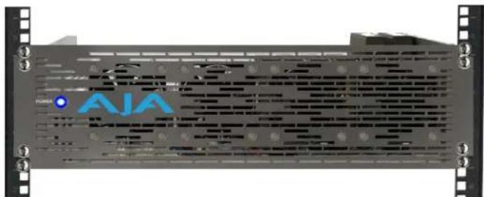
Front view of a computer rack with multiple drive units and fans (no visible text or labels)Figure 2. 19" rack-mounted DRM2 shown with (optional) Active Faceplate
natural_image
Front view of a server rack unit with AJA branding and ventilation slots (no readable text or symbols beyond branding)High Capacity
Here are some examples of what is possible with the DRM2 using only 3RU of rack space:
- 12 independent channels of 4K HDMI to 12G-SDI or 12G-SDI to 4K HDMI conversion
• 12 independent scan-conversion channels
• 12 independent Up/Down/Cross conversion channels - Up to 60 channels of HD or SD sync distribution utilizing two GEN10s and ten 3GDAs or C10DAs
• 48 channels of 3G or 12G SDI to Fiber or Fiber to SDI conversion
Features
- 3RU form-factor allows all AJA Mini-Converters to fit cleanly in the chassis.
- Flexible 12-slot frame design.
- Modular "Carrier" based Mini-Converter mounts are rugged, simple to use, and easy to access from the front or rear of the chassis. Twelve Carriers are included with the DRM2 frame, one for each slot. Additional/replacement Carriers are available.
- The powered Active Faceplate offers four fans for maximum cooling in higher ambient temperature installations.
- DRM2 200W Power Supply supports any combination of up to 12 AJA Mini Converters.
- DRM2 also supports up to 24 AJA FiDO and FiDO-2(T/R/TR) Mini-Converters by using optional DC power Y-Cables, and mounting pairs of FiDOs on single Carriers.
- Main DC Power Harness included has thirteen D5/10-PC power connectors. Twelve of the D5/10-PC power connectors are to be utilized by the Mini Converters, and one is reserved for the (optional) Active Faceplate.
- Modular Power Supply Connector also allows users the option to create custom cabling (within power specifications). For example, cables with more D5/10-PC connectors could be made for higher density installations, upon engineering review.
Front Faceplate
Two types of front faceplates are available for the DRM2 frame: a Passive Faceplate and an Active Faceplate.
Passive Faceplate
The DRM2 ships with a standard Passive Faceplate with ventilation holes. For users that want to upgrade their passive faceplate to the active version, the Active Faceplate is also available as a standalone part. See "Parts Available Separately" on page 7.
The Passive Faceplate is sufficient for rack installations which provide their own cooling, or for when lower wattage Mini-Converters are installed and lower ambient temperatures are present.
Figure 3. Passive Faceplate

natural_image
Front panel of a black electronic device with white grid patterns and mounting holes, featuring the logo 'AJA' in blue text (no readable document text beyond branding)Active Faceplate
The Active Faceplate enables the DRM2 frame to be used with higher wattage consuming Mini-Converters, and/or to be used in higher ambient temperature environments.
The DRM2-AP product configuration ships the Mini-Converter rack frame together with an Active Faceplate having four cooling fans.
Figure 4. Active Faceplate

The Active Faceplate allows for a high-density installation of AJA's most powerful Mini-Converters, without concern for heat soak. The Active Faceplate connects to the DRM2 +5V DC power supply using any available DC power connector found on the DRM2's DC Power Harness, although one is provided near the middle of the harness for this use.
If the ambient temperature is under 30C, an Active Faceplate is recommended if power consumption exceeds 100W. If the ambient temperature is over 30C, then an Active Faceplate is recommended if power consumption exceeds 75W. Please consult the Tech Specs of your Mini-Converters to calculate expected power consumption.
Figure 5. Active Faceplate Fans and Power Connector

Both DRM2 faceplate types have four "inner" mounting holes for the faceplate, in addition to the four "outer" 19" rack-mounting holes for the DRM2 frame.
Figure 6. Separate faceplate and rack mount screw holes
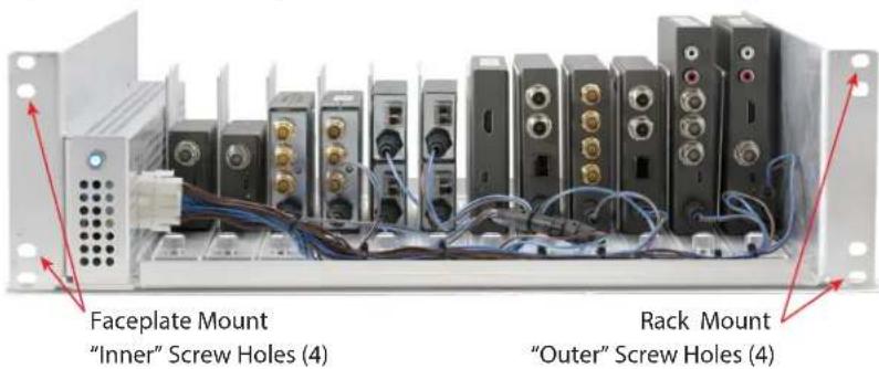
Both sets of holes may use the same size 19" rack screws.
NOTE: 19" rack rails vary in design, so use the fasteners which your rack provides.
This design allows removal and replacement of the faceplate without removing the DRM2 from the rack. This allows easy access to Mini-Converters and their cabling from the front. The above example shows all Mini-Converters connected to the DC Power Harness.
Included in the Box
Basic Order
Table 1. Shipping Contents for DRM2 or DRM2-AP Basic Order
| Item Quantity Notes | ||
| DRM2 Rack Mount Frame 1 19" rack mount frame for AJA mini-converters | ||
| Passive or Active Faceplate 1 | Passive Faceplate (with DRM2 order)- or -Active Faceplate (with DRM2-AP order) | |
| Carrier 12 Carriers include captive No-Tools secure screws | ||
| Anti-vibration screw 12 | 10-32 x 0.187 Phillips Pan HeadSecures rear of Carrier for anti-vibration use | |
| Mini-Converter rear mounting screw | 12 | 4-40 x 0.312 Phillips Flat HeadSecures rear of Mini-Converter to Carrier |
| Mini-Converter bottom mounting screw | 12 | 2-56 x 0.250 Phillips Flat HeadSecures bottom of Mini-Converter to Carrier |
Parts Available Separately
Table 2. Separately Orderable Parts
| AJA Part Number Item Quantity Notes | |||
| DRM2-AFP(Active Faceplate) | Active Faceplate | 1 | Faceplate includes four installed fans |
| DRM2-CH12-R0(Carrier Twelve Pack) | Carrier | 12 | Include captive No-Tools secure screws |
| Rear-mounting screw | 24 | 4-40 x 0.312 Phillips Flat Head | |
| Bottom-mountingscrew | 24 | 2-56 x 0.250 Phillips Flat Head | |
| DRM2-CH-R0(Carrier Single Pack) | Carrier | 1 | Includes captive No-Tools secure screw |
| Rear-mounting screw | 2 | 4-40 x 0.312 Phillips Flat Head | |
| Bottom-mountingscrew | 2 | 2-56 x 0.250 Phillips Flat Head | |
| DRM2-YC-R0(Power Cable Adapter) | DC Power Y-Cable | 1 | Adds a second +5VDC DWP male connector to any single DWP connector |
| DRM2-YC12-R0(Expansion Kit Upgrade Kit ) | DC Power Y-Cable | 12 | Adds 12 more +5VDC DWP male connectors to the DC Power Harness |
| Rear-mounting screw | 24 | 4-40 x 0.312 Phillips Flat Head | |
Rack Mount Frame with Carrier Slots
The DRM2 is a standard 19-inch, 3-RU tall, 15" deep rack mount frame with 12 Carrier Slots, into which Mini-Converter Carrier mounting brackets slide into and are secured.
Figure 7. DRM2 with empty Carriers in Carrier Slots

Mini-Converter Carriers
Mini-Converters are not mounted directly into the DRM2 frame. They are first attached to the Mini-Converter Carrier mounting brackets. The Carriers each include screws for mounting mini-converters to them, as well as a Carrier Rear Screw for optional anti-vibration use.
Figure 8. Mini-Converter Carrier mounting bracket and screws

Twelve Mini-Converters Example Configuration
Below find an example of 12 AJA Mini-Converters of various sizes installed into a single DRM2 frame.
Figure 9. DRM2 with 12 AJA Mini-Converters installed
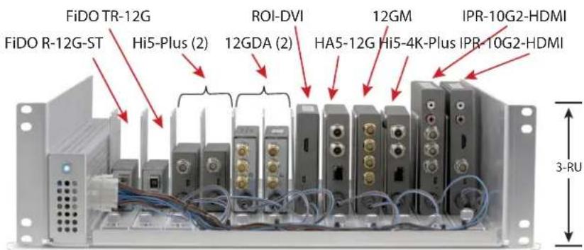
NOTE: The above example is for illustration purposes only, and is not intended to represent a specific application. Only DC power is shown connected, for clarity.
NOTE: For details on the example AJA mini-converter products shown above, see: https://www.aja.com/nav/products-mini-converters
Installation
DRM Carriers may be shipped pre-installed in the DRM2 frame. If so, first time converter installation requires removing the Carriers from their Carrier Slots inside the frame, in order to subsequently mount converters onto them. See "Remove Carrier from DRM2 Frame" on page 15; then continue on below.
Mounting Converters onto Carriers
Which of two alternative methods to use for mounting converters onto Carriers depends upon the particular model of Mini-Converter. When a particular model converter has two threaded rear-mounting holes, then the provided rear-mounting screws can be used through the carrier mounting slots in the Carrier's vertical bracket. See "Rear-Mounting Mini-Converters" on page 10.
Other Mini-Converter models which don't have rear-mounting holes, will have to be attached through the Carrier's bottom plate and into the bottom of the Mini-Converter housing. You will reuse the converter's bottom housing screws, or use those provided. See "Bottom-Mounting Mini-Converters" on page 10.
Use the appropriate method for each Mini-Converter being mounted into the DRM2. Procedures for both methods are detailed below.
Figure 10. Two methods of attaching Mini-Converters onto Carriers

natural_image
Black electronic device with four ports and a red arrow pointing to a small component (no visible text or symbols)Mount to Carrier using bottom housing screws

For each Mini-Converter having rear mounting holes which is to be installed into the DRM2 frame, follow the below steps:
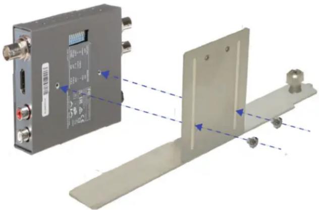
- Attach the Mini-Converter to a Carrier bracket using two of the Phillips mounting screws provided. Adjust the screw positions through the converter mounting slots in order to align with the mounting holes found in the back of the particular converter. Do not tighten the screws completely.
- Slide the converter all the way down against the Carrier bracket bottom (suggested).
- Tighten the mounting screws to secure the converter onto the Carrier. Do not over-tighten.
Figure 11. Rear-mounting a Mini-Converter onto a Carrier bracket

Figure 12. Example of a Mini-Converter correctly rear -mounted on a Carrier

natural_image
Metal mechanical component with multiple ports and mounting base (no visible text or symbols)Bottom Mounting Mini-Converters
For each Mini-Converter which does not have the two rear mounting holes, attach it instead through the bottom of a Carrier and into the converter housing as follows:
- Remove the two small Phillips screws from the bottom edge of the converter housing, and keep them on hand.
- Position the Mini-Converter onto the Carrier, orienting its DC power connection towards the front (nearest the attached No-Tools Secure Screw.)
- Replace the converter bottom housing screws through the Carrier bottom mounting slots and into the converter's bottom housing's screw holes. The finished Mini-Converter/Carrier assembly should look like this:
Figure 13. Mini-Converter correctly bottom-mounted on a Carrier

natural_image
Metallic electronic device with multiple slots and mounting bracket (no visible text or symbols)Installing Converters into DRM2 Frame
Overview
After mounting your Mini-Converter(s) onto Carrier bracket(s), you are ready to install your converter(s) into the DRM2 frame.
If you are installing Converters into a frame having a faceplate previously attached:
Temporarily remove faceplate - you will remove the DRM2 faceplate and set it aside. Removing a Passive Faceplate is simple to do, however handling an Active Faceplate requires careful attention to its power cable.
Continue below when there is no faceplate mounted on the frame:
Install Carriers with converters - you will mount Carriers into their desired Carrier Slots in the DRM2 frame and secure them. Carriers must have Mini-Converters previously mounted on them.
Install faceplate - you will reinstall the faceplate over the DRM2 and into the rack rails behind it. The Active Faceplate requires attention to its power connection.
Installing Carriers with Converters into the DRM2 Frame
- Align and loosely place a Carrier, together with its previously mounted MiniConverter, into an empty Carrier slot in the DRM2 frame. Do not try to align or tighten the No-Tools Secure Screw yet, that's for a later step; (after first making sure the Carrier rear is installed correctly, as described below.)
CAUTION: While placing a Carrier into a slot position in the DRM2 frame, be sure to keep all DC power (and any other) cables above the Carrier. Avoid letting wires get caught under a Carrier.
Figure 14. Add Carrier with Mini-Converter into slot in DRM2 Frame

natural_image
Two electronic equipment cases: a rack-mounted server unit with vertical connectors and cables, and a mounted device with cable connectors (no visible text or symbols)Figure 15. Align, insert and secure rear of Carrier

- Align the rear tab on the Carrier with the small slot on the frame.
- Slide the Carrier fully back.
- (Optional) Secure the Carrier at the rear by using a provided Carrier Rear Screw. Do not over-tighten.
NOTE: Add the anti-vibration Rear Screw to a Carrier when the DRM2 rack is to be used in a high-vibration environment (including mobile, or otherwise).
CAUTION: Do not over-tighten the Rear Screw.
- Clear any wires that have been inadvertently caught underneath a Carrier.
Figure 16. Clear wires, secure front of Carrier and connect cables

CAUTION: Do not allow any wires to get inadvertently caught underneath the Carrier. This could damage the wires or prevent the Carrier from being properly secured.
- Align and hand-tighten the attached No-Tools Secure Screw at the front of the Carrier.
- Attach the Mini-Converter DC power connector to the main DC Power Harness (or to a Y-Cable if used).
NOTE: The DWP/DWP-U/DWP-U-R1 power supplies which are supplied with all AJA Mini-Converters can alternatively be used if desired, rather than the supplied DRM2 frame's main DC Power Harness. Use of separate DC power supplies is rarely needed however, given the DRM2 200W power supply.
- Attach data and AV cables to the Mini-Converter as appropriate.
Repeat steps #1 through #8 above for each Mini-Converter Carrier that you wish to install into the DRM2 frame.
Attach Passive Faceplate
- Position the Passive Faceplate over its corresponding mounting holes in the DRM2.
CAUTION: As you position the faceplate, prevent DC power, or any other cables, from being inadvertently caught between the faceplate and DRM2 frame. Check this before tightening the rack screws.
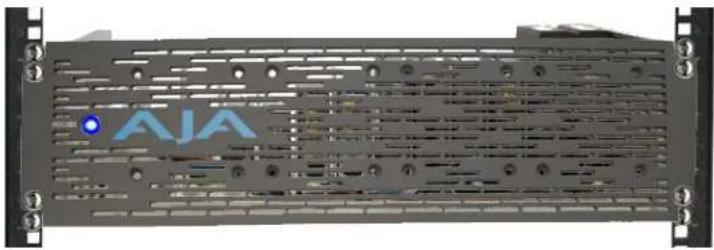
- Use four rack-mounting screws to secure the faceplate into the rack and over the DRM2.
Figure 17. Rack-Mounted DRM2 with Passive Faceplate installed
natural_image
Front view of a black server rack with ventilation grilles and a blue 'AIA' logo on the front panel (no readable text beyond logo)Attach Active Faceplate
-
Position the Active Faceplate horizontally just below the DRM2, fans facing upwards in order to bring its power cable close to the DRM2 main DC Power Harness.
-
While supporting the faceplate, connect its DC power connector to any available connector on the DC Power Harness (or to a Y-Cable if used). Ideally, use the 13th connector on the DRM2 DC Power Harness because its middle location in the harness keeps the faceplate cable short.
WARNING: Do not allow the Active Faceplate to fall, nor to hang by its DC power connection. This could damage the faceplate DC power connector and/or the DC Power Harness.
-
While still supporting the faceplate, rotate the faceplate up so that it is in its vertical mounting orientation.
-
Align the faceplate over the faceplate mounting holes in the DRM2.
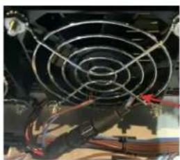
WARNING: While positioning the Active Faceplate and before fully securing it, be careful to not allow any DC power wires to accidentally push into a fan (i.e. inside of a fan's safety grill). This could cause a loud fan noise, or cause a failure of the fan, or cause other electrical damage.
Figure 18. Keep DC power and any other wires from getting inside fan
natural_image
Close-up of a car's air conditioning fan with visible wiring and red connectors (no text or symbols)natural_image
Close-up of a server fan with visible wiring and orange cables (no text or symbols)Good Practice
A suggested good practice for the Active Faceplate power connection is shown above right: tucked underneath a fan housing at bottom.
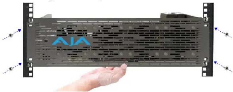
- While still supporting the faceplate, use four rack screws to attach the faceplate through the DRM2 and into the rack rails.
Figure 19. Attaching an Active Faceplate
natural_image
Hand holding a server rack with AJA branding, showing ventilation slots and mounting brackets (no readable text or symbols beyond branding)-
If you have access inside the DRM2 after the faceplate has been secured, such as through an open rack in the rear, then double-check that all fans are clear of wires by inspecting them from behind. If found, re-position the DC wires as needed.
-
While still accessing the rear of the rack, you can also check that no wires were inadvertently pinched between the faceplate and the DRM2 frame. If any pinched wires are found, simply loosen the rack mount screws slightly, remove the wire(s) then re-tighten the rack screws.
-
If not previously connected, connect the AC Power Cord to the rear of the DRM2 power supply and plug it into a suitable 100-240VAC outlet.
Uninstallation
Remove Passive Faceplate
-
Remove the four inner screws which hold the faceplate on the DRM2. Keep these screws on hand for re-installation later.
-
Remove the faceplate from the DRM2 and set it aside.
Remove Active Faceplate
- Remove the four inner screws which hold the faceplate on the DRM2. Keep these screws on hand for re-installation later.
- While removing the mounting screws, be sure to also support the faceplate to prevent it from falling while still connected to the main DC Power Harness.
Figure 20. Removing an Active Faceplate

natural_image
Hand holding a server rack with AJA branding, no visible text or symbols on the device itselfWARNING: Do not allow the Active Faceplate to fall, nor to hang by its DC power connection. This could damage the faceplate DC power connection and/or the main DC Power Harness.
- Remove the faceplate from the DRM2 frame, while supporting the faceplate.
- While still supporting the faceplate, unplug the faceplate's DC power connector from the DRM2 DC Power Harness. Do this by gently twisting counterclockwise and then pulling the connector out. If possible when pulling it out, hold by the connector instead of by the cable.
Figure 21. Locate and unplug the Active Faceplate DC power connector

natural_image
Close-up of a mechanical assembly with blue wires and red cables attached to a metallic component (no visible text or symbols)- Set aside the Active Faceplate for re-installation later.
WARNING: When handling an Active Faceplate, keep it free of contact from dust, particles, wire fragments or other debris, because such contamination could cause a loud fan noise, or cause a fan failure when power is applied.
Remove Carrier from DRM2 Frame
NOTE: When working with a frame full of converters it is generally ideal, when possible to have access from both the front and the rear of the DRM2 frame.
- Remove the DRM2 faceplate, if one is attached to the frame.
- If you have access to the rear of the frame, such as through an open chassis, you may be able to access and remove a Carrier from the rear of the frame only. Depending upon the ease of the access, and how many other converters are installed in the frame, this may or may not be convenient.
- Disconnect DC power, USB, fiber and/or AV cables from the mounted Mini-Converters (if any).
- Remove the Carrier Rear Screw (if present). Set it aside for re-installation later.
- Loosen the No-Tools Secure Screw at the front of the Carrier, until the Carrier comes loose.
- Slide the Carrier slightly forward (towards the front of the frame) to disengage the Carrier from the rear alignment slot.
- Lift the Carrier up and out of the frame.
NOTE: Avoid catching the Carrier on other cables inside the DRM2 as you move it out of the frame.
Remove Rear-Mounted Converter from Carrier
- If not previously done, remove the Carrier from the DRM2 frame (see "Remove Carrier from DRM2 Frame" on page 15.)
- From the rear side of the Carrier's vertical bracket, remove the rear-mounting screws from the converter, and set them aside for future use.
- Remove the converter from Carrier.
Remove Bottom-Mounted Converter from Carrier
- If not previously done, remove the Carrier from the DRM2 frame (see "Remove Carrier from DRM2 Frame" on page 15.)
- From the underside of the Carrier, remove the bottom housing screws from the Mini-Converter, and set them aside.
- Remove the converter from the Carrier.
- Re-insert the bottom housing screws into the carrier bottom edge of its housing.
Special Case Installations
Mounting Converters with DIP Switches
If the Mini-Converter being installed has DIP switches, these are usually found on the rear of the converter, located between the two rear mounting holes. The DIP switches will be covered by the Carrier's converter mounting bracket after the converter is installed onto it, making DIP adjustments impossible (while mounted). Thus a best practice is to adjust your DIP switches first, then mount the converter onto the Carrier.
Figure 22. Mounting a Mini-Converter with DIPS onto a Carrier bracket
natural_image
3D diagram of a device with labeled ports and mounting brackets, showing alignment arrows (no text or symbols present)When the Mini-Converter is connected to a host computer, in most cases the same functional adjustments (and more) can be made using AJA's Mini-Config software alone, instead of using the physical DIP switches.
NOTE: See "USB Connections" on page 19.
Stacking FiDO Converters Two-High
Two FiDO Mini-Converters, given their thermal characteristics, may be mounted directly on top of each other on a single DRM2 Carrier and thus the two converters will use only one Carrier slot in the DRM2 frame. Only the AJA FiDO and FiDO-2(T/R/TR) Mini-Converters are certified for this vertical-stacked configuration on a Carrier.
Below is an example DRM2 configuration with two stacked FiDOs in the frame.
Figure 23. DRM2 with four FiDO Mini-Converters using two Carrier Slots

Figure 24. Four FiDO TR-12G Mini-Converters using two Carrier Slots

FiDOs have rear mounting holes, so those are used to attach them to Carriers.
- Use the converter mounting slots and mounting screws to install the first FiDO Mini-Converter to the bracket.
- Slide it to the bottom against the Carrier.
- Tighten its mounting screws.
- Install the second FiDO above the first one, using another pair of mounting screws through the slots into the rear of the second FiDO.
Figure 25. Stacking two FiDO Mini-Converters onto one Carrier bracket

- Install the Carrier with the two FiDOs into the DRM2 in the usual way.
NOTE: See "Installing Carriers with Converters into the DRM2 Frame" on page 11.
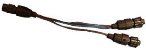
Depending on how many and what mix of converters you are installing into the frame, you may need to add a DC Power Y-Cable for the additional converters. These are simply added to any power connector on the main DC Power Harness.
Figure 26. AJA DC Power Y-Cable (optional)
natural_image
Two connected metallic USB connectors with black plastic bands (no text or symbols visible)Figure 27. Y-Cable added to DC Power Harness for stacked FiDO expansion
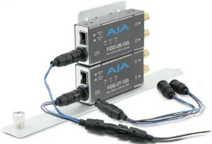
natural_image
Two AJA FIDQ-2R-12G and FIDQ-2T-12G wireless network devices connected by cables and connectors (no visible text or symbols on the devices themselves)For installing the maximum of 24 FiDOs continue below.
- Proceed to mount up to a total of 12 pairs of stacked FiDO Mini-Converters onto 12 Carriers.
- Install the dual-FiDO Carriers into the DRM2 frame in the usual way.
- Connect an AJA DC Power Y-Cable to all 12 of the DC connectors on the DRM2 main DC Power Harness. This will provide 24 DC power cables and connectors, supporting the maximum setup of 24 FiDOs.
Figure 28. Adding up to 12 Y-Cables to the main DC Power Harness

natural_image
Coiled electronic components with metallic connectors and blue wires, no visible text or symbols- Connect the (up to) 24 Y-Cable power connectors to the (up to) 24 FiDO Mini-Converters.
- Connect fiber and other remaining cables to the FIDO Mini-Converters as appropriate.
USB Connections
Below we describe use of USB hubs. USB may also be managed by KVM or KVM over IP, which are the beyond the scope of this manual.
USB Hub
There is no disadvantage to using a USB hub for Mini-Converters installed in a DRM2 frame, provided some good practices are employed:
- Use an actively-powered hub (one with an AC/DC adapter; not bus-powered).
- Use a high-quality hub, rated as compliant with USB v2.0 or higher.
- A USB v2.0 cable up to ten foot long may be used for the host computer connection.
- USB from the hub may also be extended by a suitable type of powered USB 2.0 (or higher) extender.
Figure 29. Example of a typical powered USB v2.0, 12-port hub

natural_image
Black rectangular electronic device with blue LED display (no visible text or symbols)AJA Mini-Config USB Device Select
When using AJA Mini-Config software and a USB hub, all of a DRM2 frame's connected and powered Mini-Converters may be conveniently accessed from the device select menu:
Figure 30. Mini-Config device select menu for DRM2 frame with 12 devices

Appendix A – Specifications
DRM2 Tech Specs
User Interface
• 12x mounting slots for any AJA Mini-Converters
- Converters may be installed without removing the frame from the rack
Size (w x d x h)
- 19.0" x 15.0" x 5.25" (48.26 x 38.1cm x 13.34 cm)
Weight
- DRM2 w/12 Carriers, hardware, power harness, and power cord: 9.3 lbs (4.2 kg)
• DRM2 Faceplate w/o fans .9 lbs (.4 kg)
• DRM2 Faceplate w fans 2.1 lbs (.9 kg)
Power
• Universal 100-240V, 50/60Hz power input
- 12x +5V DC regulated outputs (hardwired to power supply)
• Power Consumption: 200 Watts maximum
NOTE: the total power required by all the installed AJA Mini-Converters must be less than the DRM2 frame maximum of 200 Watts. Refer to the individual AJA Mini-Converter Tech Specs Power section, available on the AJA website, to calculate the total power for the DRM2 converter configuration.
Environment
- Operating Temperature: 0 to 40 C (32 to 104 F)
- Safe Storage Temperature (Power Off): -40 to 60 C (-40 to 140 F)
- Operating Relative Humidity: 10-90% non-condensing
- Operating Altitude: <2,500 meters (<8,000 feet)
Appendix B – Safety and Compliance
Federal Communications Commission (FCC) Compliance Notices
Class A Interference Statement
This equipment has been tested and found to comply with the limits for a Class A digital device, pursuant to Part 15, Subpart B of the FCC Rules. These limits are designed to provide reasonable protection against harmful interference in a residential installation. This equipment generates, uses, and can radiate radio frequency energy and, if not installed and used in accordance with the instructions, may cause harmful interference to radio communications. However, there is no guarantee that interference will not occur in a particular installation. If this equipment does cause harmful interference to radio or television reception, which can be determined by turning the equipment off and on, the user is encouraged to try to correct the interference by one or more of the following measures:
- Reorient or relocate the receiving antenna.
- Increase the separation between the equipment and receiver.
- Connect the equipment into an outlet on a circuit different from that to which the receiver is connected.
- Consult the dealer or an experienced radio/TV technician for help.
FCC Caution
This device complies with Part 15 of the FCC Rules. Operation is subject to the following two conditions: (1) This device may not cause harmful interference, and (2) this device must accept any interference received, including interference that may cause undesired operation.
Canadian ICES Statement
Canadian Department of Communications Radio Interference Regulations
This digital apparatus does not exceed the Class A limits for radio-noise emissions from a digital apparatus as set out in the Radio Interference Regulations of the Canadian Department of Communications. This Class A digital apparatus complies with Canadian ICES-003.
European Union, European Free Trade Association (EFTA) and United Kingdom Regulatory Compliance
This equipment may be operated in the countries that comprise the member countries of the European Union, European Free Trade Association and the United Kingdom. These countries, listed in the following paragraph, are referred to as The European Community throughout this document:
AUSTRIA, BELGIUM, BULGARIA, CROATIA, CZECH REPUBLIC, DENMARK, ESTONIA, FINLAND, FRANCE, GERMANY, GREECE, HUNGARY, ICELAND, IRELAND, ITALY, LATVIA, LIECHTENSTEIN, LITHUANIA, LUXEMBOURG, MALTA, NETHERLANDS, NORWAY, POLAND, PORTUGAL, REPUBLIC OF CYPRUS, ROMANIA, SLOVAK REPUBLIC, SLOVENIA, SPAIN, SWEDEN, SWITZERLAND, UNITED KINGDOM
Declaration of Conformity
Marking by these symbols indicates compliance with the Essential Requirements of the EMC Directive of the European Union 2014/30/EU.

This equipment meets the following conformance standards:
Safety
EN 62368-1: 2014 + A11 (T-Mark License),
IEC 62368-1: 2014 (CB Scheme Report/Certificates)
Emissions
EN 55032: 2015 + A11: 2020, CISPR 32: 2015,
EN 61000-3-2: 2014, EN 61000-3-3: 2013
Immunity
EN 55035: 2017 + A11: 2020, EN 61000-4-2:2009,
EN 61000-4-3:2006+A1:2008+A2:2010,
EN 61000-4-4: 2012, EN 61000-4-5: 2014 + A1: 2017, EN 61000-4-6: 2014,
EN 61000-4-11: 2020
Environments: E2, E3 and E4
The product is also licensed for additional country specific standards as required for the International Marketplace.

Warning! This is a Class A product. In a domestic environment, this product may cause radio interference, in which case, the user may be required to take appropriate measures.
This symbol on the product or its packaging indicates that this product must not be disposed of with your other household waste. Instead, it is your responsibility to dispose of your waste equipment by handing it over to a designated collection point for the recycling of waste electrical and electronic equipment. The separate collection and recycling of your waste equipment at the time of disposal will help conserve natural resources and ensure that it is recycled in a manner that protects human health and the environment. For more information about where you can drop off your waste for recycling, please contact your local authority, or where you purchased your product.
Korea KCC Compliance Statement
사용자 안내문
Taiwan Compliance Statement
警告使用者:
This is a Class A product based on the standard of the Bureau of Standards, Metrology and Inspection (BSMI) CNS 13438, Class A. In a domestic environment this product may cause radio interference in which case the user may be required to take adequate measures.
Japan Compliance Statement
This is a Class A product based on the standard of the VCCI Council (VCCI 32: 2016). If this equipment is used in a domestic environment, radio interference may occur, in which case, the user may be required to take corrective actions.
Translated Warning and Caution Messages
The following caution statements, warning conventions, and warning messages apply to this product and manual.

Warning Symbol

Hazard Symbol

Caution Symbol
Before Operation Please Read These Instructions

Warning! Read and follow all warning notices and instructions marked on the product or included in the documentation.
Warning! Do not use this device near water and clean only with a dry cloth.
Warning! Do not block any ventilation openings. Install in accordance with the manufacturer's instructions.
Warning! Do not install near any heat sources such as radiators, heat registers, stoves, or other apparatus (including amplifiers) that produce heat.
Warning! Do not defeat the safety purpose of the polarized or grounding-type plug. A polarized plug has two blades with one wider than the other. A grounding type plug has two blades and a third grounding prong. The wide blade or the third prong are provided for your safety. If the provided plug does not fit into your outlet, consult an electrician for replacement of the obsolete outlet.
Warning! Since the Mains plug is used as the disconnection for the device, it must remain readily accessible and operable.
Warning! Protect the power cord from being walked on or pinched particularly at plugs, convenience receptacles, and the point where they exit from the device.
Warning! Unplug this device during lightning storms or when unused for long periods of time.
Warning! Refer all servicing to qualified service personnel. Servicing is required when the device has been damaged in any way, such as power-supply cord or plug is damaged, liquid has been spilled or objects have fallen into the device, the device has been exposed to rain or moisture, does not operate normally, or has been dropped.
Warning! Disconnect the external AC power supply line cord(s) from the mains power before moving the unit.
Warning! Only use attachments and accessories specified and/or sold by the manufacturer.
Hazard! High Voltage. This situation or condition can cause injury due to electric shock.
Warranty and Liability Information
Limited Warranty
AJA Video Systems, Inc. (AJA Video) warrants that this product will be free from defects in materials and workmanship for a period of five years from the date of purchase. If a product proves to be defective during this warranty period, AJA Video, at its option, will either repair the defective product without charge for parts and labor, or will provide a replacement in exchange for the defective product.
In order to obtain service under this warranty, you the Customer, must notify AJA Video of the defect before the expiration of the warranty period and make suitable arrangements for the performance of service. The Customer shall be responsible for packaging and shipping the defective product to a designated service center nominated by AJA Video, with shipping charges prepaid. AJA Video shall pay for the return of the product to the Customer if the shipment is to a location within the country in which the AJA Video service center is located. Customer shall be responsible for paying all shipping charges, insurance, duties, taxes, and any other charges for products returned to any other locations.
This warranty shall not apply to any defect, failure or damage caused by improper use or improper or inadequate maintenance and care. AJA Video shall not be obligated to furnish service under this warranty a) to repair damage resulting from attempts by personnel other than AJA Video representatives to install, repair or service the product, b) to repair damage resulting from improper use or connection to incompatible equipment, c) to repair any damage or malfunction caused by the use of non-AJA Videoparts or supplies, or d) to service a product that has been modified or integrated with other products when the effect of such a modification or integration increases the timeor difficulty of servicing the product.
THIS WARRANTY IS GIVEN BY AJA VIDEO IN LIEU OF ANY OTHER WARRANTIES, EXPRESS OR IMPLIED. AJA VIDEO AND ITS VENDORS DISCLAIM ANY IMPLIED WARRANTIES OF MERCHANTABILITY OR FITNESS FOR A PARTICULAR PURPOSE. AJA VIDEO'S RESPONSIBILITY TO REPAIR OR REPLACE DEFECTIVE PRODUCTS IS THE WHOLE AND EXCLUSIVE REMEDY PROVIDED TO THE CUSTOMER FOR ANY INDIRECT, SPECIAL, INCIDENTAL OR CONSEQUENTIAL DAMAGES IRRESPECTIVE OF WHETHER AJA VIDEO OR THE VENDOR HAS ADVANCE NOTICE OF THE POSSIBILITY OF SUCH DAMAGES.
Index
A
Active Faceplate 5
AJA Mini-Config 19
AJA Support 2
Attach an Active Faceplate 13
Attach an Passive Faceplate 12
B
Basic Order 7
C
Configure Carrier Bracket(s) 11
Converters into the DRM2 Frame 11
D
Dimensions 20
E
Environment 20
F
Features 5
Front Faceplates 5
H
High Capacity 4
|
Included in the box
Installation 7,9
Install Carriers into the DRM2 Frame 11
Installing Carriers with Converters 11
Installing Converters into the DRM2 Frame 11
M
Mini-Converter Carriers 8
Mini-Converter Frame for 19-inch Racks 4
Mini-Converter Mounting Carriers 8
Mini-Converter Mounting Hardware 8
Mounting 24 FIDO Converters 16
Mounting Converters onto Carriers 9
Mounting Converters with DIP Switches 16
Mounting Mini-Converters using bottom holes 10
Mounting Mini-Converters using rear holes 10
O
Overview 4
Overview of Installation 8
P
Parts Available Separately 7
Passive Faceplate 5
Power 20
R
Rack Mount Frame 8
Rack Mount Frame with Carrier Slots 8
Remove Active Faceplate 14
Remove Bottom-Mounted Converter from Carrier 16
Remove Carrier from DRM2 Frame 15
Remove Passive Faceplate 14
Remove Rear-Mounted Converter from Carrier 15
Replace the front faceplate 13
S
Safety and Compliance 21
Separately Available Parts
Special Case Installations 16
Specifications 20
Stacking FiDO Converters Two-high on Carriers 16
T
Twelve Mini-Converters Example Configuration 9
U
USB Connections 19
USB Device Select 19
USB Hub 19
W
Warranty and Liability 29


- Installation and Operation Guide
- Trademarks
- Copyright
- Contacting AJA Technical Support or Sales
- Contents
- Notices 2
- Chapter 1 – Introduction .....4
- Chapter 2 – Installation .....7
- Appendix A – Specifications ..... 20
- Appendix B – Safety and Compliance ..... 21
- Warranty and Liability Information....29
- Index. 30
- Chapter 1 – Introduction
- Overview
- Mini-Converter Frame for 19-inch Racks
- High Capacity
- Features
- Front Faceplate
- Passive Faceplate
- Active Faceplate
- Included in the Box
- Basic Order
- Parts Available Separately
- Rack Mount Frame with Carrier Slots
- Mini-Converter Carriers
- Twelve Mini-Converters Example Configuration
- Installation
- Mounting Converters onto Carriers
- Bottom Mounting Mini-Converters
- Installing Converters into DRM2 Frame
- Installing Carriers with Converters into the DRM2 Frame
- Attach Passive Faceplate
- Attach Active Faceplate
- Uninstallation
- Remove Passive Faceplate
- Remove Active Faceplate
- Remove Carrier from DRM2 Frame
- Remove Rear-Mounted Converter from Carrier
- Remove Bottom-Mounted Converter from Carrier
- Special Case Installations
- Mounting Converters with DIP Switches
- Stacking FiDO Converters Two-High
- USB Connections
- USB Hub
- AJA Mini-Config USB Device Select
- Appendix A – Specifications
- DRM2 Tech Specs
- User Interface
- Size (w x d x h)
- Weight
- Power
- Environment
- Appendix B – Safety and Compliance
- Federal Communications Commission (FCC) Compliance Notices
- Class A Interference Statement
- FCC Caution
- Canadian ICES Statement
- European Union, European Free Trade Association (EFTA) and United Kingdom Regulatory Compliance
- Declaration of Conformity
- Korea KCC Compliance Statement
- Taiwan Compliance Statement
- 警告使用者:
- Japan Compliance Statement
- Translated Warning and Caution Messages
- Before Operation Please Read These Instructions
- Warranty and Liability Information
- Limited Warranty
- Index
- A
- B
- C
- D
- E
- F
- H
- |
- M
- O
- P
- R
- S
- T
- U
- W
Brand : AJA
Model : DRM2
Category : Video Converter