FCIW59209 - Cooker Hansa - Free user manual and instructions
Find the device manual for free FCIW59209 Hansa in PDF.


| Product Type | Freestanding Electric Cooker |
| Brand | Hansa |
| Model | FCIW59209 |
| Dimensions (H x W x D) | 85 cm x 60 cm x 50 cm |
| Voltage | 400V 3N~50Hz / 400V 2N~50Hz |
| Maximum Power Rating | 10.5 kW |
| Hob Type | Ceramic Induction |
| Number of Cooking Zones | 4 (2 x 210 mm, 2 x 160 mm) |
| Booster Function | Yes (up to 3000W on 210 mm zones, 1400W on 160 mm zones) |
| Oven Type | Multifunction with fan and ring heater |
| Oven Functions | Rapid preheat, defrost, grill, fan grill, convection, bottom heat, top+bottom, etc. |
| Electronic Programmer | Yes (timer, minute minder, meat probe) |
| Child Lock | Yes |
| Residual Heat Indicator | Yes (H > 60°C, h 45-60°C) |
| Pan Detection | Yes |
| Automatic Warm-Up | Yes |
| Keep Warm Function | Yes (2-hour limit) |
| Oven Lighting | Halogen, 25W, 230V |
| Cleaning | Steam cleaning function, removable door and inner glass panel |
| Safety Features | Overheating protection, automatic switch-off, child lock |
| Installation Requirements | Adjustable feet, anti-tip bracket, proper ventilation |
Frequently Asked Questions - FCIW59209 Hansa
User questions about FCIW59209 Hansa
0 question about this device. Answer the ones you know or ask your own.
Ask a new question about this device
Download the instructions for your Cooker in PDF format for free! Find your manual FCIW59209 - Hansa and take your electronic device back in hand. On this page are published all the documents necessary for the use of your device. FCIW59209 by Hansa.
USER MANUAL FCIW59209 Hansa
natural_image
Line drawing of a standard electric stove with four burners and a front panel (no text or symbols)NAUDOJIMO INSTRUKCIJA / ELEKTRINĖ VIRYKLĖ
KASUTUSJUHEND / ELEKTRIPLIIT ET
LIETOŠANAS INSTRUKCIJA / ELEKTRISKĀ PLĪTS
INSTRUCTION
MANUAL
LV
LT
SAUGOS NURODYMAI 4
GAMINIO APRAŠYMAS 9
JRENGIMAS 12
APTARNAVIMAS 15
NAUDOJIMAS 27
KEPIMAS ORKAITĖJE – PRAKTIŠKI PATARIMAI 32
VIRYKLĖS VALYMAS IR PRIEŽIŪRA 34
VEIKSMAI AVARIJOS METU 39
TECHNINIAI DUOMENYS 41
ET
OHUTUSJUHISED 43
ELEKTRIENERGIA KOKKUHOID 46
SEADME KIRJELDUS 48
PAIGALDAMINE 51
KASUTAMINE 54
TOIDUVALMISTAMINE PLIIDIL - PRAKTILISED NÕUANDED 70
HOOLDUS JA PESEMINE 72
CLEANING AND MAINTENANCE 151
GERBIAMAS PIRKĖJAU,
natural_image
Simple black-and-white line drawing of a tree with cloud-like canopy and two wavy lines at base (no text or symbols)natural_image
Simple line drawing of a recycling symbol (three chasing arrows), no text or labels present.natural_image
Pure geometric diagram with four circles and diagonal lines, no text or symbols present
Valdymo skydas
flowchart
graph TD
    A["9"] --> B["7"]
    C["8."] --> D["5"]
    E["8."] --> F["3"]
    G["8.8."] --> H["4"]
    I["10"] --> J["6"]
    K["8"] --> L["2"]
    M["3"] --> N["5"]
    O["8."] --> P["5"]
    Q["8."] --> R["1"]
natural_image
Isometric line drawing of a square frame with rounded corners and a central hole (no text or symbols)Padėklas kondit. gaminiams kepti*
natural_image
Technical line drawing of a rectangular metal grate or rack structure (no text or symbols)Grotelès griliui*
natural_image
Line drawing of a rectangular tray with a small recessed slot (no text or symbols)Kepimo padėklas*
natural_image
Technical line drawing of a mechanical clamp or bracket device (no text or symbols)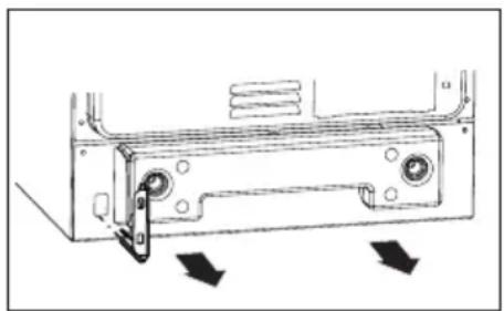
natural_image
Technical line drawing of a mechanical component with directional arrows indicating movement or force (no text or symbols)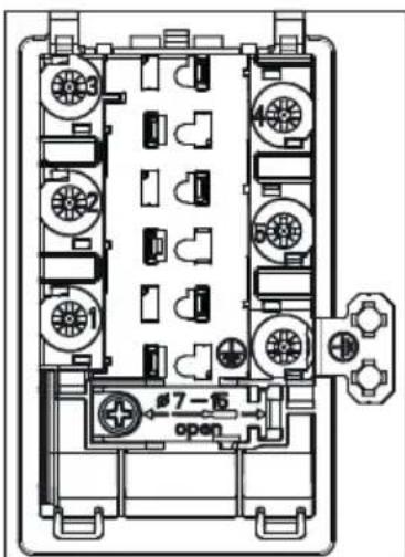
GALIMU JUNGIMU SCHEMA
natural_image
Simple line drawing of a cooking pot on a tray with steam rising (no text or symbols)natural_image
Six identical cooking pots with crossed X marks, arranged horizontally (no text or symbols)Indu charakteristika.
natural_image
Diagram showing a cooking pot with three circular components below, no text or symbols presentnatural_image
Line drawing of a hand using a tool to cut or spread material into fragments (no text or symbols)Dėmių šalinimas
natural_image
Technical line drawing of a rectangular electronic device casing with internal components and a small component at the bottom (no text or symbols)Orkaitès lemputè
Dèmesio!
natural_image
Three sequential diagrams showing mechanical or electrical components with directional arrows, no text or symbols present.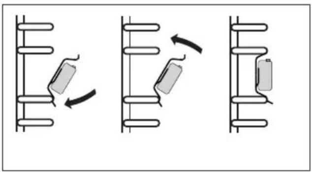
natural_image
Three diagrams showing mechanical or electrical components with curved arrows indicating motion (no text or symbols)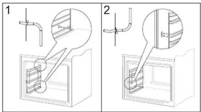
natural_image
Technical line drawing of a mechanical assembly with an inset showing a close-up of a component (no text or symbols present)natural_image
Diagram of a rectangular electronic device with mounting brackets and a separate panel labeled C, showing no text or symbols.VIRYKLÈS VALYMAS IR PRIEŽIŪRA
natural_image
Simple black-and-white line drawing of a tree with cloud-like canopy and two wavy lines at base (no text or symbols)natural_image
Simple line drawing of a recycling symbol (three chasing arrows), no text or labels present.natural_image
Isometric line drawing of a square frame with rounded corners and a central hole (no text or symbols)Ahjuplaat*
natural_image
Technical line drawing of a rectangular metal grate or rack structure (no text or symbols)natural_image
Line drawing of a rectangular tray or container with a recessed slot (no text or symbols)Küpsetusplaat*
*Mõned mudelid
Pliidi paigaldamine
natural_image
Technical line drawing of a mechanical clamp or lever device (no text or symbols)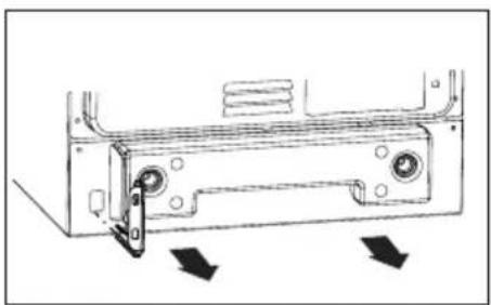
natural_image
Technical line drawing of a mechanical component with directional arrows indicating movement or force (no text or symbols)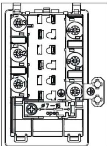
ELEKTRIÜHENDUSTE SKEEM
natural_image
Simple line drawing of a cooking pot with steam rising from a tray (no text or symbols)natural_image
Six identical cooking pots with crossed X marks, arranged horizontally (no text or symbols)Nõude iseloomustus.
natural_image
Diagram showing a cooking pot with three circular components below, no text or symbols presentnatural_image
Line drawing of a hand using a tool to cut or spread material from a rectangular block (no text or symbols)natural_image
Technical line drawing of a rectangular electronic device casing with internal components and a small component on the right side (no text or symbols)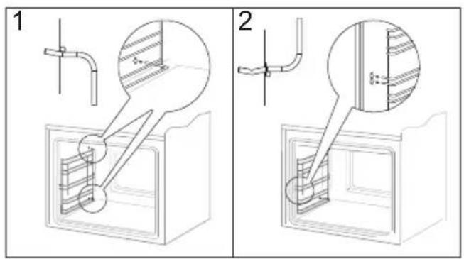
natural_image
Three diagrams showing a battery moving in different positions (no text or symbols present)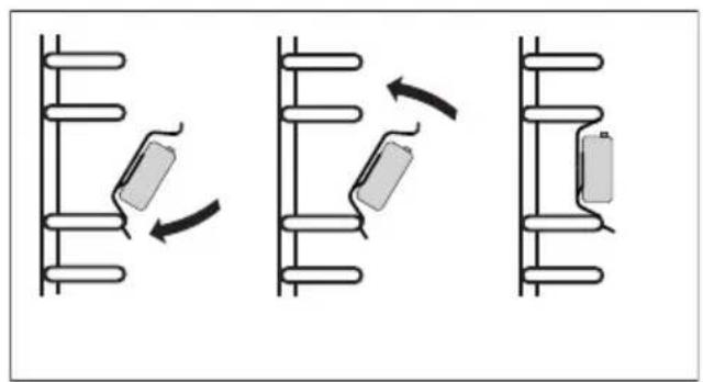
natural_image
Diagram showing three sequential mechanical or electrical assembly steps with rotating components (no text or symbols)*Mõned mudelid
Ukse äravõtmine
natural_image
Technical line drawing of a mechanical assembly with an inset showing a close-up of a component (no text or symbols present)natural_image
Technical diagram of a rectangular electronic component with mounting holes and a separate labeled panel (no text or symbols present)natural_image
Simple black-and-white line drawing of a tree with cloud-like canopy and two wavy lines at base (no text or symbols)natural_image
Simple line drawing of a recycling symbol (three chasing arrows), no text or labels present.natural_image
Isometric line drawing of a square frame with rounded corners and a central hole (no text or symbols)natural_image
Isometric line drawing of a rectangular metal grate or rack structure with no text or symbolsnatural_image
Line drawing of a rectangular tray or container with a recessed slot (no text or symbols)natural_image
Technical line drawing of a mechanical clamp or bracket component (no text or symbols)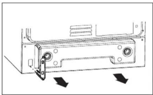
natural_image
Technical line drawing of a mechanical component with directional arrows indicating movement or force (no text or symbols)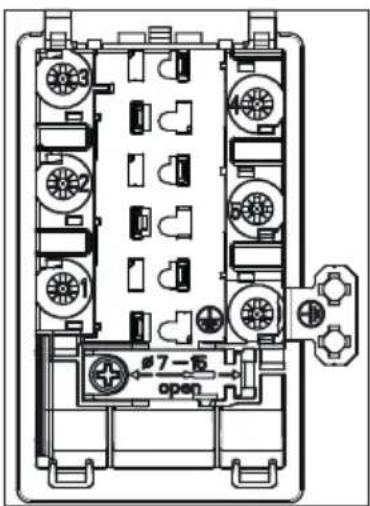
IESPËJAMO PIESLËGUMU SHËMA
natural_image
Simple line drawing of a cooking pot with arrows indicating flow or movement (no text or symbols)natural_image
Six identical cooking pots on a stove with crossed-out black X marks, no text or symbols presentnatural_image
Diagram showing a cooking pot with three circular components below, no text or symbols presentnatural_image
Line drawing of a hand using a tool to cut or spread material, with no text or symbols present.natural_image
Three-step diagram showing mechanical assembly with rotating components and directional arrows (no text or symbols)natural_image
Diagram showing three sequential mechanical or electrical assembly steps with no visible text or symbolsnatural_image
Technical line drawing of a rectangular electronic device casing with internal components and an arrow pointing to a component (no text or symbols present)*daži modeli
VIRTUVES PLİTS TİRİŞANA UN KOPŞANA
Durvju noņemšana
natural_image
Technical line drawing of a mechanical assembly with an inset showing a close-up of a component (no text or symbols present)natural_image
Diagram of a rectangular electronic component with mounting flanges and a separate panel labeled 'C' (no text or symbols on the component itself)VIRTUVES PLİTS TİRİŞANA UN KOPŞANA
The cooker is exceptionally easy to use and extremely efficient. After reading the instruction manual, operating the cooker will be easy.
Before being packaged and leaving the manufacturer, the cooker was thoroughly checked with regard to safety and functionality.
Before using the appliance, please read the instruction manual carefully.
By following these instructions carefully you will be able to avoid any problems in using the appliance.
It is important to keep the instruction manual and store it in a safe place so that it can be consulted at any time.
It is necessary to follow the instructions in the manual carefully in order to avoid possible accidents.
Caution!
Do not use the cooker until you have read this instruction manual.
The cooker is intended for household use only.
The manufacturer reserves the right to introduce changes which do not affect the operation of the appliance.
SAFETY INSTRUCTIONS
Warning: The appliance and its accessible parts become hot during use. Care should be taken to avoid touching heating elements. Children less than 8 years of age shall be kept away unless continuously supervised.
This appliance can be used by children aged from 8 years and above and persons with reduced physical, sensory or mental capabilities or lack of experience and knowledge if they have been given supervision or instruction concerning use of the appliance in a safe way and understand the hazards involved. Children shall not play with the appliance. Cleaning and user maintenance shall not be made by children without supervision.
Warning: Unattended cooking on a hob with fat or oil can be dangerous and may result in fire.
NEVER try to extinguish a fire with water, but switch off the appliance and then cover flame e.g. with a lid or a fire blanket.
Warning: Danger of fire: do not store items on the cooking surfaces.
Warning: If the surface is cracked, switch off the appliance to avoid the possibility of electric shock.
Metallic objects, such as knives, forks, spoons and lids should not be placed on the hob surface since they can get hot.
After use, switch off the hob element by its control and do not rely on the pan detector.
During use the appliance becomes hot. Care should be taken
to avoid touching heating elements inside the oven.
Warning: Accessible parts may become hot during use. Young children should be kept away.
Do not use harsh abrasive cleaners or sharp metal scrapers to clean the oven door glass since they can scratch the surface, which may result in shattering of the glass.
Warning: Ensure that the appliance is switched off before replacing the lamp to avoid the possibility of electric shock.
You should not use steam cleaning devices to clean the appliance.
During the pyrolytic oven cleaning process the oven chamber can reach a very high temperature. Consequently, the appliance outer surfaces can heat up more than usual, so keep children away at all times.
Danger of burns! Hot steam may escape when you open the oven door. Be careful when you open the oven door during or after cooking. Do NOT lean over the door when you open it. Please note that depending on the temperature the steam can be invisible.
Caution: The cooking process has to be supervised. A short term cooking process has to be supervised continuously.
Warning: Use only hob guards designed by manufacturer of the cooking appliance or indicated by the manufacturer of the appliance in the instructions for use as suitable or hob guards incorporated in the appliance. The use of inappropriate guards can cause accidents.
• Always keep children away from the cooker.
While in operation direct contact with the cooker may cause burns!
- Ensure that small items of household equipment, including connection leads, do not touch the hot oven or the hob as the insulation material of this equipment is usually not resistant to high temperatures.
- Do not leave the cooker unattended when frying. Oils and fats may catch fire due to overheating or boiling over.
- Do not allow the hob to get soiled and prevent liquids from boiling over onto the surface of the hob. This refers in particular to sugar which can react with the ceramic hob and cause irreversible damage. Any spillages should be cleaned up as they happen.
- Do not place pans with a wet bottom on the warmed up heating zones as this can cause irreversible changes to the hob (irremovable stains).
- Use pans that are specified by the manufacturer as designed for use with a ceramic hob.
- If any defects, deep scratches, cracks or chips appear on the ceramic hob, stop using the cooker immediately and contact the service centre.
- Do not switch on the hob until a pan has been placed on it.
- Do not use pans with sharp edges that may cause damage to the ceramic hob.
- Do not look directly at the halogen heating zones (not covered by a pan) when they are warming up.
- Do not put pans weighing over 15 kg on the opened door of the oven and pans over 25 kg on the hob.
- Do not use harsh cleaning agents or sharp metal objects to clean the door as they can scratch the surface, which could then result in the glass cracking.
- Do not use the cooker in the event of a technical fault. Any faults must be fixed by an appropriately qualified and authorised person.
- In the event of any incident caused by a technical fault, disconnect the power and report the fault to the service centre to be repaired.
- Never allow children to remain unattended near the cooktop nor to play with the control panel.
- People with life function support implants (such as a heart pacemaker, an insulin pump, or a hearing aid) must make sure that the operation of these devices is not disturbed by the induction plate (induction plate frequency range is 20 to 50 kHz).
- The appliance has been designed only for cooking. Any other use (for example for heating) does not comply with its operating profile and may cause danger.

natural_image
Simple black-and-white line drawing of a tree with cloud-like canopy and two wavy lines at base (no text or symbols)Using energy in a responsible way not only saves money but also helps the environment. So let's save energy! And this is how you can do it:
• proper pans for cooking.
Pans with thick, flat bases can save up to 1/3 on electric energy. Remember to cover pans if possible otherwise you will use four times as much energy!
- Match the size of the saucepan to the surface of the heating zone.
A saucepan should never be smaller than a heating zone.
- Ensure heating zones and pan bases are clean.
Soils can prevent heat transfer – and repeatedly burnt—on spillages can often only be removed by products which cause damage to the environment.
- Do not uncover the pan too often (a watched pot never boils!).
Do not open the oven door unnecessarily often.
Switch off the oven in good time and make use of residual heat.
For long cooking times, switch off heating zones 5 to 10 minutes before finishing co-oking. This saves up to 20% on energy.
Only use the oven when cooking larger dishes.
Meat of up to 1 kg can be prepared more economically in a pan on the cooker hob.
- Make use of residual heat from the oven. If the cooking time is greater than 40 minutes switch off the oven 10 minutes before the end time.
Important! When using the timer, set appropriately shorter cooking times according to the dish being prepared.
- Only grill with the ultrafan after closing the oven door.
- Make sure the oven door is properly closed.
Heat can leak through spillages on the door seals. Clean up any spillages immediately.
- Do not install the cooker in the direct vicinity of refrigerators/freezers.
Otherwise energy consumption increases unnecessarily.

natural_image
Simple line drawing of a recycling symbol (three chasing arrows), no text or labels present.During transportation, protective packaging was used to protect the appliance against any damage. After unpacking, please dispose of all elements of packaging in a way that will not cause damage to the environment.
All materials used for packaging the appliance are environmentally friendly; they are 100% recyclable and are marked with the appropriate symbol.
Caution! During unpacking, the packaging materials (polythene bags, polystyrene pieces, etc.) should be kept out of reach of children.
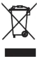
Old appliances should not simply be disposed of with normal household waste, but should be delivered to a collection and recycling centre for electric and electronic equipment. A symbol shown on the product, the instruction manual or the packaging shows that it is suitable for recycling.
Materials used inside the appliance are recyclable and are labelled with information concerning this. By recycling materials or other parts from used devices you are making a significant contribution to the protection of our environment.
Information on appropriate disposal centres for used devices can be provided by your local authority.
DESCRIPTION OF THE APPLIANCE
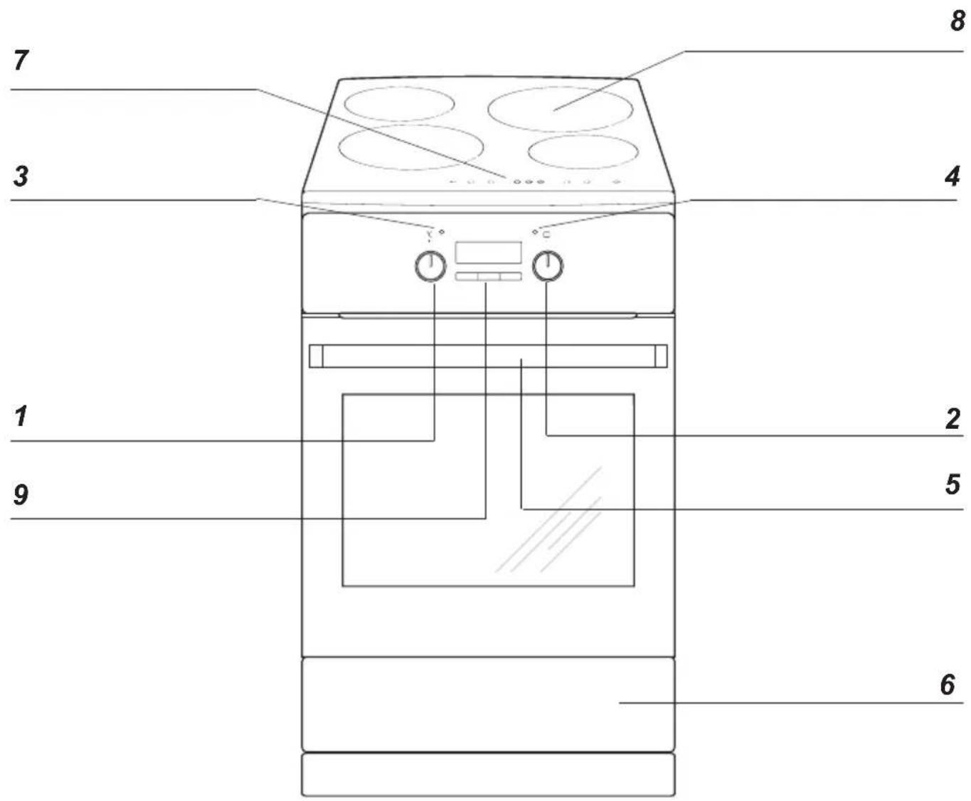
1 Temperature control knob
2 Oven function selection knob
3 Temperatureregulatorsignal light
4 Oven operation signal light
5 Door lock indicator light
6 Oven door handle
7 Control Panel
8 Ceramic induction cooker
9 Electronic programmer
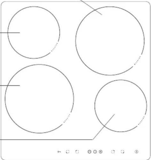
DESCRIPTION OF THE APPLIANCE
Booster induction cooking zone (rear right) ∅ 210
Booster induction cooking zone (rear left) ∅ 160
Booster induction cooking zone(front left) ∅ 210
Booster induction cooking zone (front right) ∅ 160
natural_image
Pure geometric diagram with four circles and a diagonal line, no text or symbols presentControl Panel
flowchart
graph TD
    A["9"] --> B["7"]
    B --> C["3"]
    C --> D["8. 8."]
    D --> E["5"]
    E --> F["8 10 8"]
    F --> G[":8.8.:"]
    G --> H["4 6 2"]
    H --> I["3"]
    I --> J["8. 8."]
    J --> K["5"]
    K --> L["1"]
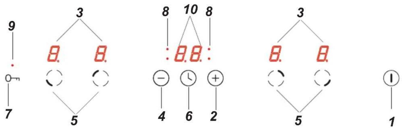
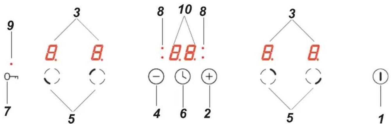
- On/off sensor
- Higher heat setting selector
- Cooking zone indicator
- Lower heat setting selector
- Cooking zone selection sensor
- Timer sensor
- Child lock sensor
- Timer indicator light
- Child lock indicator light
- Timer display
Cooker fittings:
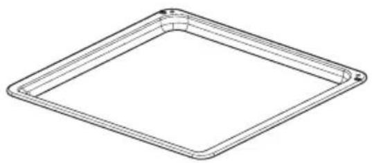
natural_image
Line drawing of a square frame with rounded corners and a small hole at the top (no text or symbols)Baking tray*
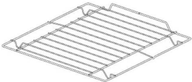
natural_image
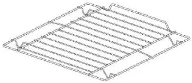
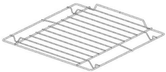
Isometric line drawing of a rectangular metal grate or rack structure with no text or symbolsGrill grate (drying rack)*
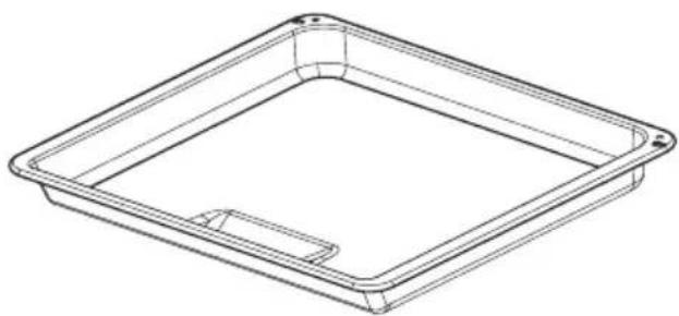
natural_image
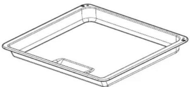
Line drawing of a rectangular tray with a recessed inner frame and a small cutout on the side (no text or symbols)Frying tray*
*optional
Installing the cooker
- The kitchen should be dry and airy and have effective ventilation according to the existing technical provisions.
- The room should be equipped with a ventilation system that pipes away exhaust fumes created during combustion. This system should consist of a ventilation grid or hood. Hoods should be installed according to the manufacturer's instructions. The cooker should be placed so as to ensure free access to all control elements.
- Coating or veneer used on fitted furniture must be applied with a heat resistant adhesive (100°C). This prevents surface deformation or detachment of the coating. If you are unsure of your furniture's heat resistance, you should leave approximately 2 cm of free space around the cooker. The wall behind the cooker should be resistant to high temperatures. During operation, its back side can warm up to around 50°C above the ambient temperature.
- The cooker should stand on a hard, even floor (do not put it on a base).
- Before you start using the cooker it should be leveled, which is particularly important for fat distribution in a frying pan. To this purpose, adjustable feet are accessible after removal of the drawer. The adjustment range is +/- 5 mm.
Mounting the overturning prevention bracket.
The bracket is mounted to prevent overturning of the cooker. When the overturning prevention bracket is installed, a child who climbs on the oven door will not overturn the appliance.
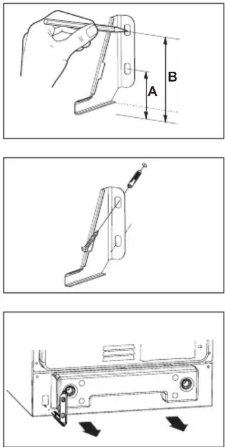
Cooker, height 900 mm
A=104 mm
B=147 mm
Electrical connection
Warning!
All electrical work should be carried out by a suitably qualified and authorised electrician. No alterations or wilful changes in the electricity supply should be carried out.
Fitting guidelines
The cooker is manufactured to work with three-phase alternating current (400V 3N\~50Hz). The voltage rating of the cooker heating elements is 230V. The appliance can be configured for two phase power supply (400V 2N\~50 Hz) by bridging the appropriate terminals according to wiring diagram. The connection diagram is also found on the cover of the connection box. Remember that the connection wire should match the connection type and the power rating of the cooker.
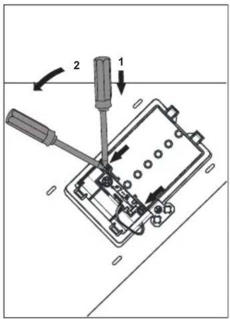
The connection cable must be secured in a strain-relief clamp.
Warning!
Remember to connect the safety circuit to the connection box terminal marked with ⏚. The electricity supply for the cooker must have a safety switch which enables the power to be cut off in case of emergency. The distance between the working contacts of the safety switch must be at least 3 mm.
Before connecting the cooker to the power supply it is important to read the information on the data plate and the connection diagram.
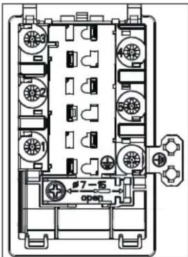
Connection diagram
Caution! Voltage of heating elements 230V
Caution! In the event of any connection the safety wire must be connected to the ⏚ PE terminal.
| Recommended type of connection lead | ||||
| 1 | For 400 V 2N~50Hz two-phase connection with a neutral conductor, terminals 2-3 are bridged and terminals 4-5 are bridged, individual phase conductors are connected to terminals 1 and 2-3 respectively, neutral conductor is connected to bridged terminals 4-5, and the protective earth conductor is connected to the earthing terminal. | 2N~ | 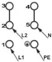 | H05VV-F4G4 4x 4 mm2 |
| 2 | For 400 V 3N~50Hz three-phase connection with a neutral conductor, terminals 4-5 are bridged, individual phase conductors are connected to terminals 1, 2, and 3 respectively, neutral conductor is connected to bridged terminals 4-5, and the protective earth conductor is connected to the earthing terminal. | 3N~ | 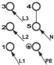 | H05VV-F5G1,5 5x 1,5 mm2 |
| L1, L2, L3 - phase conductors; N - neutral conductor; PE - protective earth (grounding) conductorThe arrows in the above diagrams indicate where you need to connect the individual cable conductors. | ||||
| Important: To ensure compliance with the applicable safety requirements, a switch must be fitted which isolates all terminals and has a contact distance of at least 3 mm. (Can be a master switch). | 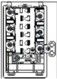 | Type of power supply cable |
| For 400V 2N~50Hz two-phase connection with a neutral conductor, terminals 2-3 are bridged and terminals 4-5 are bridged, individual phase conductors are connected to terminals 1 and 2-3 respectively, neutral conductor is connected to bridged terminals 4-5, and the protective earth conductor is connected to the earthing terminal ⏻. | 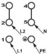 | H05VV-F4G4 4x 4 mm2 |
| For 400V 3N~50Hz three-phase connection with a neutral conductor, terminals 4-5 are bridged, individual phase conductors are connected to terminals 1, 2, and 3 respectively, neutral conductor is connected to bridged terminals 4-5, and the protective earth conductor is connected to the earthing terminal ⏻ | 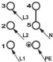 | H05VV-F5G2,5 5x 2,5 mm2 |
| L1, L2, L3 - Live wires; N - Neutral wire; PE - Earth wireThe arrows in the above diagrams indicate where you need to connect the individual cable wires. | ||
Before using the oven for the first time
- Remove packaging, clean the interior of the cooker.
- B before using the oven, you have to clean your oven. Use a damp cloth with a mild detergent. Never use corrosive or abrasive cleaners.
- Switch on the ventilation in the room or open a window.
- Heat the oven (to a temperature of 250^ C, for approx. 30 min.), remove any stains and wash carefully.
Important!
In ovens equipped with the electronic programmer, the time "0.00" will start flashing in the display field upon connection to the power supply.
The programmer should be set with the current time. (See Electronic programmer). If the current time is not set operation of the oven is impossible.
Important!
The inside of the oven should only be washed with warm water and a small amount of washing-up liquid.
Electronic timer
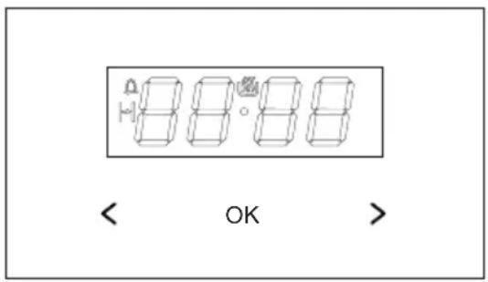
ok - button to select mode of operation
- plus button
< - minus button
- appliance on indicator
- Minute minder
- Duration
Set current time
When the appliance is plugged into the electrical mains supply, or when power is restored after power outage, the digital display will show flashing 0.00
- press and hold ok (or simultaneously the buttons < / > ) until you will see 📄 on the display and the dot below the symbol is flashing,
- press and hold the < / > buttons within 7 seconds to set the current time.
To store the new time setting, wait approximately 7 seconds after time has been set.
The dot below the symbol will stop flashing. You can adjust the time later. To do this, press the < / > buttons simultaneously and adjust the current time while the dot below the symbol is flashing.
Note:
The oven can be turned on when you see the symbol on the display.
Minute Minder
You can active the Minute Minder at any time, regardless of the status of other functions.
The Minute Minder can be set from 1 minute up to 23 hours and 59 minutes.
To set the Minute Minder:
- press the ok button, then the display will show flashing 🔒 symbol:
- use the < / > buttons to set the Minute Minder. The display will show the set time and Minute Minder symbol 📐. Once the set time elapses, alarm sounds and the 🔊 flashes
- to mute the alarm press and hold ok or simultaneously press and hold < / >, the symbol will be off and the display will show the current time.
Note!
If no button is touched, alarm will turn off automatically after approximately 7 minutes.
Timed operation
To set the appliance to switch off after a specific duration:
- set the operation mode knob and the temperature control knob to your preferred settings.
- press ok repeatedly until the display shows dur (duration) briefly and the symbol will be flashing,
- set the desired duration from 1 minute to 10 hours using the < / > buttons.
The set duration will be memorised after about 7 seconds. The display will show the current time and the symbol.
Once the Duration has elapsed the oven will turn off automatically. You will hear an alarm and the ⏻ symbol will be flashing.
- set the oven function selector knob and the temperature selector knob in off position.,
- to mute the alarm press and hold ok or simultaneously press and hold < / > , the will be off and the display will show the current time.
Cancel settings
Timer and Timed operation settings may be cancelled at any time.
- to cancel the Duration, press < / > simultaneously.
Cancel Minute Minder settings:
- press the ok button to select the minute minder,
- press the < / > buttons
Change the beep tone
You can change the beep tones as follows:
- press and hold the < / > button simultaneously,
- press ok to select tone, and the display will flash:
- press < / > to select the desired tone: use the > button to select tones 1 to 3 use the < button to select tones 3 to 1.
Adjust display brightness
You can adjust display brightness 1 to 9, where 1 is the darkest and 9 is the brightest. The brightness setting applies to an inactive control panel, i.e. when none of controls are used 7 seconds.
You can adjust display brightness as follows:
● simultaneously press the < / > buttons
- press ok repeatedly to select the bri (brightness) setting — the settings can be accessed in sequence ton (tone) and bri (brightness).
- use the < / > buttons to select the desired brightness use the > button to select tones 1 to 9 use the < button to select tones 9 to 1.
Note:
The display is at its brightest setting when active, i.e. a control was touched within the last 7 seconds.
Night Mode
The display is dimmed during the night hours 22:00 — 06:00.
Meat Probe
80^
when temperature at meat probe is above 0^ C.
If meat probe is plugged in, the two digits on
the meat probe and the two digits at the right
side show the set point value. If the probe temperature is lower than the recommended probe temperature settings
| is higher than the maximum setting temperature of 99°C, the display reads the maximum setting temperature. probe, the program is started and the nominal temperature is set to 80 °C. The value of when timer is still in start up mode. The meat probe alarm can be reset by pressing any key. | minimum setting temperature of 30 °C, the display reads '30' - if the probe temperature [°C] | |
| TYPE OF MEAT | TEMPERATURE | |
| PORK Fillet Roast | 85 - 90 80 - 85 | |
| BEEF Roast beef or fillet Rare as the set temperature can be changed as long as the temperatures are displayed, but not Medium Well done | 90 - 95 50 - 55 65 - 70 75 - 80 | |
| VEAL | 85 - 90 | |
| LAMB active meat probe program of a pending alarm can be reset by disconnecting the meat VENISON | 85 - 90 80 - 85 | |
| FISH e.g. salmon trout, cod | 80 - 85 | |
The use of temperature probe is recommended when cooking large portions of meat (at least 1 kg).
The use of temperature probe is not recommended when cooking poultry and meat with bones.
When not in use, disconnect the temperature probe from its socket and remove from oven chamber.
Important!
Use only original temperature probe supplied with the appliance.
Before using the appliance for the first time
- thoroughly clean your induction hob first. The induction hob should be treated with the same care as a glass surface.
- switch on the ventilation in the room or open a window, as the appliance could emit an unpleasant smell during first use.
- operate the appliance while observing all safety guidelines.
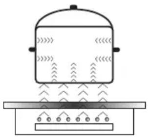
Induction cooking zone operation principle
natural_image
Simple line drawing of a steam locomotive with tracks and wheels (no text or symbols)Electric oscillator powers a coil placed inside the appliance. This coil produces a magnetic field, which induces eddy currents in the cookware.
These eddy currents induced by the magnetic field cause the cookware to heat up.
This requires the use of pots and pans whose base is ferromagnetic, in other words susceptible to magnetic fields.
Overall, induction technology is characterized by two advantages:
- the heat is only emitted by the cookware and its use is maximised,
- there is no thermal inertia, since the cooking starts immediately when the pot is placed on the hob and ends once it is removed.
Certain sounds can be heard during normal use of the induction hob, which do not affect its correct operation.
- Low-frequency humming. This noise arises when the cookware is empty and stops when water is poured or food is placed in the cookware.
- High-frequency whizz. This noise arises in cookware made of multiple layers of different materials at maximum heat setting. The noise intensifies when using two or more cooking zones at maximum heat setting. The noise will stop or reduce when heat setting is reduced.
- Creaking noise. This noise arises in cookware made of multiple layers of different materials. The noise intensity depends on how the food is cooked.
- Buzzing. Buzzing can be heard when electronics cooling fan operates.
The noises that can be heard during the normal appliance operation are the result of the cooling fan operation, cooking method, cookware dimensions, cookware material and the heat setting. These noises are normal and do not indicate a fault.
The protective device:
If the hob has been installed correctly and is used properly, any protective devices are rarely required.
Fan: protects and cools controls and power components. It can operate at two different speeds and is activated automatically. Fan runs until the electronic system has sufficiently cooled down regardless of the appliance or the cooking zones being turned on or off.
Temperature sensor: Temperature of electronic circuits is continuously monitored by a temperature sensor. If temperature is raised beyond a safe level, this protection system will reduce cooking zone heat setting or shut down the cooking zones adjacent to the overheated electronic circuits.
Pan detection: allows the hob to detect pans placed on a cooking zone. Small objects placed on the cooking zone (eg, spoon, knife, ring ...) will not be recognised as pans and the hob will not operate.

Pan detector
Pan detector is installed in induction hobs. Pan detector starts heating automatically when a pan is detected on a cooking zone and stops heating when it is removed. This helps save electricity.
- When an suitable pan is placed on a cooking zone, the display shows the heat setting.
- Induction requires the use of suitable cookware with ferromagnetic base (see Table).

If a pan is not placed on a cooking zone or the pan is unsuitable, the symbol is displayed. The cooking zone will not operate. If a pan is not detected within 10 minutes, the cooking zone will be switched off.
Switch off the cooking zone using the touch control sensor field rather than by removing the pan.

Pan detector does not operate as the on/off sensor.
The induction hob is equipped with electronic touch control sensor fields, which are operated by touching the marked area with a finger.
Each time a sensor field is touched, an acoustic signal can be heard.

When switching the appliance on or off or changing the heat setting, attention should be paid that only one sensor field at a time is touched. When two or more sensor fields are touched at the same time (except timer and child lock), the appliance ignores the control signals and may trigger a fault indication if sensor fields are touched for a long time.
When you finish cooking switch off the cooking zone using touch control sensor fields and do not rely solely on the pan detector.
The high-quality cookware is an essential condition for efficient induction cooking.

Select cookware for induction cooking

natural_image
Six cooking pots with crossed X marks, no text or symbols presentCookware characteristics.
- Always use high quality cookware, with perfectly flat base. This prevents the formation of local hot spots, where food might stick. Pots and pans with thick steel walls provide superior heat distribution.
- Make sure that cookware base is dry: when filling a pot or when using a pot taken out of the refrigerator make sure its base is completely dry before placing it on the cooking zone. This is to avoid soiling the surface of the hob.
- Lid prevents heat from escaping and thus reduces heating time and lowers energy consumption.
- To determine if cookware is suitable, make sure that its base attracts a magnet.
- Cookware base has to be flat for optimal temperature control by the induction module.
- The concave base or deep embossed logo of the manufacturer interfere with the temperature induction control module and can cause overheating of the pot or pan.
- Do not use damaged cookware such as cookware with deformed base due to excessive heat.
- When you use large ferromagnetic base cookware, whose diameter is less than the total diameter of the cookware, only the ferromagnetic base heats up. This results in a
situation where it is not possible to uniformly distribute the heat in the cookware. If the ferromagnetic area is reduced due to inclusion of aluminium parts then the effective heated area can be reduced. Problems with the detection of the cookware could arise or cookware may not be detected at all. To achieve optimum cooking results, the diameter of the ferromagnetic base should match that of the cooking zone. If cookware is not detected in a given cooking zone, it is advisable to try it in a smaller cooking zone.
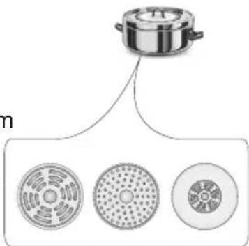
For induction cooking us only ferromagnetic base materials such as:
- enamelled steel
- cast iron
- special stainless steel cookware designed for induction cooking.
| Marking of kitchen cookware | 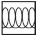 | Check for marking indicating that the cookware is suitable for induction cooking. |
| Use magnetic cookware (enamelled steel, ferrite stainless steel, cast iron). The easiest way to determine if your cookware is suitable is to perform the „magnet test”. Find a generic magnet and check if it sticks to the base of the cookware. | ||
| Stainless Steel Cookware | is not detected | |
| With the exception of the ferromagnetic steel cookware | ||
| Aluminium Cookware is not detected | ||
| Cast iron High efficiency | ||
| Caution: cookware can scratch the hob surface | ||
| Enamelled steel High efficiency | ||
| Cookware with a flat, thick and smooth base is recommended | ||
| Glass Cookware is not detected | ||
| Porcelain Cookware is not detected | ||
| Cookware with copper base | Cookware is not detected | |
Cookware size.
- In order to achieve best cooking results, use cookware with bottoms (ferromagnetic part) of the size corresponding to the size of the cooking zone.
- Using cookware with the bottom diameter smaller than the cooking zone size will reduce the effectiveness of the cooking zone and increase cooking time.
- Cooking zones have a lower pot detection limit that depends on the diameter of ferromagnetic part of the pot bottom and the pot material. The use of an unsuitable pot might lead to pot being undetected by a cooking zone.

Control Panel
- Immediately after the appliance is connected to electrical mains, all displays will light up briefly. Your induction hob is then ready for use.
- The induction hob is equipped with electronic touch control sensor fields, which are operated by touching with a finger for at least 1 second.
- Touching of a sensor field is accompanied by an acoustic signal to acknowledge.

No objects should be placed on the sensor fields (this could cause an error). Touch sensor fields should be always kept clean.
Switch on the appliance
To switch on the appliance touch and hold the on/off sensor field (1) for at least 1 second. All displays (3) will show the number "0".

If none of the sensor fields is touched within 10 seconds, the appliance switches itself off.
Switch on the cooking zone
Once the appliance is switched on using the on/off touch sensor (1), select a cooking zone (5) within the next 10 seconds.
- When a cooking zone selection sensor field (5) is touched, "0" on the corresponding heat setting indicator display will pulsate.
- Set the desired heat setting using the "+" (2) or "-" (4) sensor fields.

If none of the sensor fields is touched within 10 seconds of switching on the appliance, the cooking zone switches off.

A cooking zone is active when its display shows a digit or a letter. This indicates the cooking zone is ready for the heat setting to be set or changed.
Selecting the cooking zone heat setting
When the cooking zone display (3) shows pulsating "0", start setting the desired heat setting using the "+" (2) or "-" (4) sensor field.
Switch off cooking zones
- A given cooking zone must be active. Heat setting display pulsates.
- To switch off a cooking zone touch the on/off sensor field or touch the sensor (5) for 3 seconds.
Switch off the appliance
- The appliance operates when at least one cooking zone is on.
- To switch off the appliance touch the on/off sensor (1).
If a cooking zone is still hot, the relevant display (3) will show the letter "H" to indicate residual heat.
Booster function "P"
The Booster Function increases the nominal power of the 210 mm cooking zone from 2000W to 3000W,
∅ 160 mm cooking zone from 1200W to 1400W,
In order to activate the Booster function, select the cooking zone, set the heat setting to "9" and then touch the "+" (2) sensor field again. The letter "P" will be shown on the display.
To deactivate the Booster function, touch the "-" (4) sensor field to reduce the heat setting or lift the cookware from the cooking zone.

For 210 mm and 160 mm cooking zone, operation of the Booster function is limited to 10 minutes. Once the Booster function is automatically deactivated, the cooking zone continues to operate at its nominal power.
The Booster function can be reactivated, provided the appliance electronic circuits and induction coils are not overheated.
When the pot is lifted from the cooking zone when the Booster function is in operation, it remains active and the countdown continues.
When the appliance electronic circuits or induction coils overheat when the Booster function is in operation, it is automatically deactivated. The cooking zone continues to operate at its nominal power.
Booster function control

Depending on the model, the cooking zones are paired vertically or crosswise. Total power is shared within the paired cooking zones.
If you attempt to enable the Booster function for both cooking zones simultaneously, the maximum power available would be exceeded. In that case the heat setting of the first activated cooking zone will be reduced to the highest level available.
The child lock function
The Child Lock function protects the appliance from inadvertent operation by children. The appliance can be operated once the child lock function has been released.
The Child Lock function can be set when the appliance turned on or off.
Turn Child Lock on/off
Touch and hold sensor (7) for 5 seconds to turn Child Lock on/off. Indicator light (9) is on when the Child Lock function is on.

The Child Lock function remains set until it is released even after the appliance has been switched off and then switched on again. Disconnecting the appliance from electrical mains deactivates the Child Lock.
Residual heat indicator
Heat energy that remains accumulated in the cooking zone after cooking is called the residual heat. The appliance displays two different levels of residual heat. When a cooking zone temperature is above 60^ C and the cooking zone or the appliance is switched off, the relevant cooking zone display will show the letter "H". Residual heat indication is displayed as long as the cooking zone temperature exceeds 60^ C. When a cooking zone temperature is between 45^ C and 60^ C, the relevant cooking zone display will show the letter "h" indicating low residual heat. When a cooking zone temperature is below 45^ C the residual heat indication is turned off.

When residual heat indicator is on, do not touch the cooking zone as there is a risk of burns and do not place on it any items sensitive to heat!


During failure of power supply "H" residual heat indicator is not displayed. However, cooking zones may still be hot!
Limiting the operating time
In order to increase efficiency, the induction hob is fitted with a operating time limiter for each of the cooking zones. The maximum operating time is set according to the last heat setting selected.
If you do not change the heat setting for a long time (see table) then the associated cooking zone is automatically switched off and the residual heat indicator is activated. However, you can switch on and operate individual cooking zones at any time in accordance with the operating instructions.
| Cooking heat setting | Maximum operating time (hours) |
| U | 8 |
| 1 | 8 |
| 2 | 8 |
| 3 | 5 |
| 4 | 5 |
| 5 | 5 |
| 6 1,5 | |
| 7 1,5 | |
| 8 1,5 | |
| 9 1,5 | |
| P 0,16 |
Automatic warm-up function
- Touch sensor (5) to activate the selected cooking zone
- Then touch "+" (2) or "-" (4) to set the desired heat setting in the 1-8 range and then touch sensor (5) again.
- The display will alternate between the letter A and the heat setting.
After a certain time of operation at boosted power, the cooking zone switches back to the heat setting set, which will be shown on the display.
| Cooking heat setting | The duration of the automatic warm-up function (minutes) |
| - | |
| 1 0,8 | |
| 2 1,2 | |
| 3 2,3 | |
| 4 3,5 | |
| 5 4,4 | |
| 6 7,2 | |
| 7 | 2 |
| 8 3,2 |

If a pot is lifted from the cooking zone and replaced before the warm-up countdown is completed, the warm-up function will resume and countdown will continue until completed.
Timer
Timer function makes cooking easier by making it possible to set Duration. It can also be used as a Kitchen Timer.
Set the Timer
Timer function makes cooking easier by making it possible to set Duration. It can also be used as a Kitchen Timer.
- Touch cooking zone selection sensor field (5) to select a cooking zone. The number "0" will pulsate.
- Touch "+" (2) or "-" (4) sensor field to set the desired heat setting ranging from 1 to 9.
- Then activate timer by touching (6) sensor fields within 10 seconds.
- Touch "+" (2) or „-” (4) sensor field to set the desired cooking time (01 to 99 minutes).
- Timer indicator light (8) of a relevant cooking zone will be on.

Timer countdown can be set independently for all cooking zones.

If more than one timer is set the shortest duration is displayed. Timer indicator light (8) of a relevant cooking zone will flash.
Change Timer Duration
Timer Duration setting can be changed at any time.
- Touch cooking zone selection sensor field (5) to select a cooking zone. The display will pulsate.
- Then activate timer by touching (6) sensor fields within 10 seconds.
- Use "+" (2) or "-" (4) sensor field to adjust the timer setting.
Check Timer Duration
To check progress of Timer countdown at any time, touch the timer sensor field (6). Timer indicator light (8) of a relevant cooking zone will flash.
OPERATION
Stop the Timer
When the set time has elapsed an acoustic signal is sounded, which can be muted by touching any sensor field. If no sensor field is touched, the acoustic signal will stop automatically after 2 minutes.
To stop the timer countdown before the set Duration has elapsed:
- Touch cooking zone selection sensor field (5) to select a cooking zone. The display will become bright.
- Then touch and hold sensor (6) for 3 seconds or adjust duration using the "+" (2) or "-" (4) down to "00"
Kitchen Timer
When no cooking zones are in use, the Timer function can be used as a regular Kitchen Timer.
Set Kitchen Timer
When the appliance is off:
- Switch on the appliance by touching the on/off sensor (1).
- Then touch sensor (6) to activate kitchen timer.
- Use "+" (2) or "-" (4) sensor field to adjust the Kitchen Timer setting.
Stop Kitchen Timer
When the set Duration has elapsed an acoustic signal is sounded, which can be muted by touching any sensor field. If no sensor field is touched, the acoustic signal will stop automatically after 2 minutes.
To stop the timer countdown before the set Duration has elapsed:
- Touch and hold sensor (6) for 3 seconds or adjust duration using the "+" (2) or "-" (4) down to "00"
- Kitchen Timer function does not affect cooking zone operation.

Kitchen timer is reset when the timer function is activated.
Keeping food warm
Keep warm function allows for keeping food warm on a cooking zone. The selected cooking zone operates at a low heat setting. Cooking zone's heat setting is automatically adjusted so that food temperature is kept at a temperature of about 65^ C. Thanks to this, ready to serve, warm food retains its taste and does not stick to the pot's bottom. This function can be also used to melt butter or chocolate.
For the keep food warm function to operate correctly, use a flat base pot or frying pan, so that base temperature is accurately measured by the temperature sensor fitted in the cooking zone.
The Keep Warm function can be activated for any cooking zone.
Due to a risk of the growth of microorganisms, it is not recommended to keep food warm for a long time, so the Keep Warm function is switched off after 2 hours.
Keep warm setting is an additional heat setting available between "0" and "1" and is indicated on the display as "U".
Keep warm setting is activated in the same way as described in the section
Switch on the cooking zone
Keep warm setting is deactivated in the same way as described in the section
Switch off cooking zones
Oven functions and operation.
Oven with automatic air circulation (including a fan and ring heater)
The oven can be heated up using the bottom and top heaters, the grill or the ultra-fan heater. Operation of the oven is controlled by the oven function knob – to set a required function you should turn the knob to the selected position, and the temperature regulator knob – to set a required function you should turn the knob to the selected position.
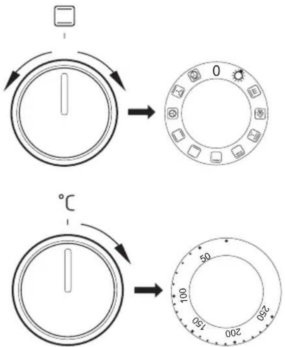
The oven can be switched off by setting both of these knobs to the position “●”/“0”.
Caution!
When selecting any heating function (switching a heater on etc.) the oven will only be switched on after the temperature has been set by the temperature regulator knob.
0 Oven is off

Independent oven lighting
Set the knob in this position to light up the oven interior.

Rapid Preheating
Ring heater and roaster on. Use to preheat the oven.

Defrosting
Only fan is on and all heaters are off.

Fan and combined grill on
When the knob is turned to this position, the oven activates the combined grill and fan function. In practice, this function allows the grilling process to be speeded up and an improvement in the taste of the dish. You should only use the grill with the oven door shut.

Enhanced roaster (super roaster)
In this setting both roaster and top heater are on. This increases temperature in the top part of the oven's interior, which makes it suitable for browning and roasting of larger portions of food.

Roaster on.
Roasting is used for cooking of small portions of meat: steaks, schnitzel, fish, toasts, Frankfurter sausages, (thickness of roasted dish should not exceed 2-3 cm and should be turned over during roasting).

Bottom heater on
When the knob is set to this position the oven is heated using only the bottom heater. Baking of cakes from the bottom until done (moist cakes with fruit stuffing).

Top and bottom heaters on
Set the knob in this position for conventional baking. This setting is ideal for baking cakes, meat, fish, bread and pizza (it is necessary to preheat the oven and use a baking tray) on one oven level.

Convection with ring heating element
Setting the knob in this position allows the oven to be heated up by a heating element with air circulation forced by a rotating fan fitted in the central part of the back wall of the of and chamber. Lower baking temperatures than in the conventional oven can be used. Heating the oven up in this manner ensures uniform heat circulation around the dish being cooked in the oven.

Top heater, bottom heater and fan are on.
This knob setting is most suitable for baking cakes. Convection baking (recommended for baking).
When the ☐ functions have been selected but the temperature knob is set to zero only the fan will be on. With this function you can cool the dish or the oven chamber.

Convection with ring heating element and bottom heater on
With this setting the convection fan and bottom heater are on, which increases the temperature at the bottom of the cooked dish. Intense heat from the bottom, moist cakes, pizza.
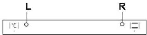
Switching on the oven is indicated by two signal lights, 3, 4, turning on. The 4 light turned on means the oven is working. If the 3 light goes out, it means the oven has reached the set temperature. If a recipe recommends placing dishes in a warmed-up oven, this should be not done before the 3 light goes out for the first time. When baking, the Llight will temporarily come on and go out (to maintain the temperature inside the oven). The 4 signal light may also turn on at the knob position of "oven chamber lighting".
Use of the grill
The grilling process operates through infrared rays emitted onto the dish by the incandescent grill heater.
In order to switch on the grill you need to:
- Set the oven knob to the position marked grill ☐,
- Heat the oven for approx. 5 minutes (with the oven door shut).
- Insert a tray with a dish onto the appropriate cooking level; and if you are grilling on the grate insert a tray for dripping on the level immediately below (under the grate).
- Close the oven door.
For grilling with the function grill and combined grill the temperature must be set to 210^ C ( 200^ C*), but for the function fan and grill it must be set to a maximum of 190^ C.
*oven door with 2 glass panels
Warning!
When using function grill it is recommended that the oven door is closed. When the grill is in use accessible parts can become hot. It is best to keep children away from the oven.
BAKING IN THE OVEN – PRACTICAL HINTS

Baking
- we recommend using the baking trays which were provided with your cooker;
- it is also possible to bake in cake tins and trays bought elsewhere which should be put on the drying rack; for baking it is better to use black trays which conduct heat better and shorten the baking time;
- shapes and trays with bright or shiny surfaces are not recommended when using the conventional heating method (top and bottom heaters), use of such tins can result in undercooking the base of cakes;
- when using the ultra-fan function it is not necessary to initially heat up the oven chamber, for other types of heating you should warm up the oven chamber before the cake is inserted;
- before the cake is taken out of the oven, check if it is ready using a wooden stick (if the cake is ready the stick should come out dry and clean after being inserted into the cake);
- after switching off the oven it is advisable to leave the cake inside for about 5 min.;
- temperatures for baking with the ultra-fan function are usually around 20 – 30 degrees lower than in normal baking (using top and bottom heaters);
- the baking parameters given in Table are approximate and can be corrected based on your own experience and cooking preferences;
- if information given in recipe books is significantly different from the values included in this instruction manual, please apply the instructions from the manual.

Roasting meat
- cook meat weighing over 1 kg in the oven, but smaller pieces should be cooked on the cooker hob.
- use heatproof ovenware for roasting, with handles that are also resistant to high temperatures;
- when roasting on the drying rack or the grate we recommend that you place a baking tray with a small amount of water on the lowest level of the oven;
- it is advisable to turn the meat over at least once during the roasting time and during roasting you should also baste the meat with its juices or with hot salty water – do not pour cold water over the meat.
BAKING IN THE OVEN – PRACTICAL HINTS
Oven with automatic air circulation (including a fan and ring heater)
| Type of dish | Type of heating | Temperature (°C) | Level Time | (min.) |
| Sponge cake |  | 160 - 200 2 - 3 | 30 - 50 | |
| Yeast cake/ Pound cake |  | 160 - 170 1) | 3 25 - 40 | 2) |
| Yeast cake/ Pound cake |  | 155 - 170 1) | 3 25 - 40 | 2) |
| Pizza 200 - 230 | [DAZO] | 1) | 2 - 3 15 - 25 | |
Fish 210 - 220 2 45 -  | ||||
| Fish |  | 160 - 180 2 - 3 | 45 - 60 | |
| Fish |  | 190 2 - 3 60 | - 70 | |
| Sausages |  | 210 (200*) 4 14 | - 18 | |
| Beef 225 - 250 2 120 [BTTC] 50 | ||||
| Beef |  | 160 - 180 2 120 | - 160 | |
| Beef |  | 180 - 190 2 100 | - 150 | |
| Pork |  | 160 - 230 2 90 | - 150 | |
| Pork | [ZKTW] | 160 - 190 2 90 | - 150 | |
| Pork | [664S] | 180 - 190 2 100 | - 150 | |
| Chicken |  | 180 - 190 2 70 | - 90 | |
| Chicken |  | 160 - 180 2 45 | - 60 | |
| Chicken |  | 175 - 190 2 60 | - 70 | |
| Vegetables |  | 190 - 210 2 40 | - 50 | |
| Vegetables |  | 170 - 190 3 40 | - 50 | |
* oven door with two glass panels
The times are apply to dish that is placed into a cold oven. For the preheated oven, the times should be reduced by about 5-10 minutes.
1) Preheat
2) Baking smaller items
Note: The figures given in Tables are approximate and can be adapted based on your own experience and cooking preferences.
By ensuring proper cleaning and maintenance of your cooker you can have a significant influence on the continuing fault-free operation of your appliance.
Before you start cleaning, the cooker must be switched off and you should ensure that all knobs are set to the “●”/“0” position. Do not start cleaning until the cooker has completely cooled.
Ceramic hob
- The hob should be cleaned regularly after each use. If possible, it is recommended that the hob is washed while still warm (after the heating zone indicator goes off). Do not allow the hob to get heavily stained; particularly from burnt-on spillages from boiled over liquids.
- When cleaning do not use cleaning agents with a strong abrasive effect, such as e.g. scouring powders containing an abrasive, abrasive compounds, abrasive stones, pumice stones, wire brushes and so on. They may scratch the hob surface, causing irreversible damage.
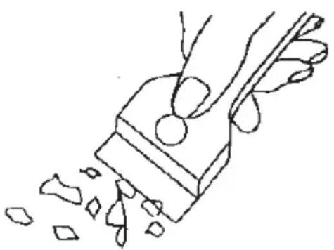
- Large spillages that are firmly stuck to the hob can be removed by a special scraper; but be careful not to damage the ceramic hob frame when doing this.
natural_image
Line drawing of a hand using a tool to cut or spread material, with no text or symbols present.Caution! The sharp blade should always be protected by adjusting the cover (just push it with your thumb). Injuries are possible so be careful when using this instrument – keep out of reach of children.
- Appropriate light cleaning or washing products are recommended, such as e.g. any kind of liquids or emulsions for fat removal. If the recommended products are not available, it is advisable to use a solution of warm water with a little washing-up liquid or cleaning products for stainless steel sinks.
Oven
- The oven should be cleaned after every use. When cleaning the oven the lighting should be switched on to enable you to see the surfaces better.
- The oven chamber should only be washed with warm water and a small amount of washing-up liquid.
- After cleaning the oven chamber wipe it dry.
Caution!
Do not use cleaning products containing abrasive materials for the cleaning and maintenance of the glass front panel.
Caution!
Do not use cleaning products containing abrasive materials for the cleaning and maintenance of the glass front panel.
- Steam Cleaning function:
-pour 250ml of water (1 glass) into a bowl placed in the oven on the first level from the bottom,
- close the oven door,
- set the temperature knob to 50^ C, and the function knob to the bottom heater position ☐
- heat the oven chamber for approximately 30 minutes,
- open the oven door, wipe the chamber inside with a cloth or sponge and wash using warm water with washing-up liquid.
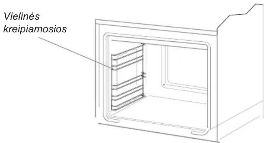
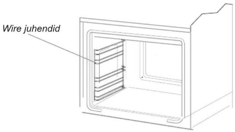
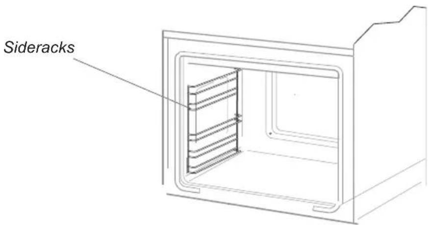
Wire shelf supports
(Telescopic guides do not appear in all furnace models)
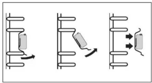
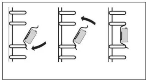
Wire shelf supports are esay to remove for wasking. Pull the front catch, then tilt the support and remove from the rear catch.
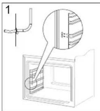
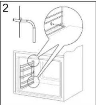
Removing wire shelf supports
The runners should be taken out and washed along with the side racks. Before putting trays on the telescopic runners they should be pulled out (if the oven is warmed up the runners should be pulled out by hooking the back edge of trays on the bumpers in the front part of the telescopic runners) and then insert them together with a tray.
natural_image
Three diagrams showing mechanical or electrical components with directional arrows, no text or symbols present.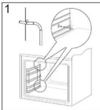
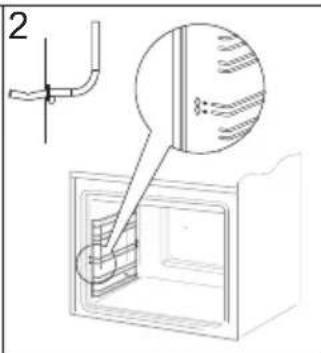
Installing wire shelf supports
natural_image
Three sequential diagrams showing mechanical assembly or motion, with no visible text, numbers, or symbols.*optional
Door removal
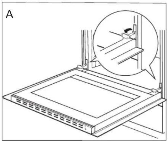
In order to obtain easier access to the oven chamber for cleaning, it is possible to remove the door. To do this, tilt the safety catch part of the hinge upwards (fig. A). Close the door lightly, lift and pull it out towards you. In order to fit the door back on to the cooker, do the inverse. When fitting, ensure that the notch of the hinge is correctly placed on the protrusion of the hinge holder. After the door is fitted to the oven, the safety catch should be carefully lowered down again. If the safety catch is not set it may cause damage to the hinge when closing the door.
natural_image
Technical line drawing of a mechanical assembly with an inset showing a close-up of a component (no text or symbols present)Tilting the hinge safety catches
Removing the inner panel
-
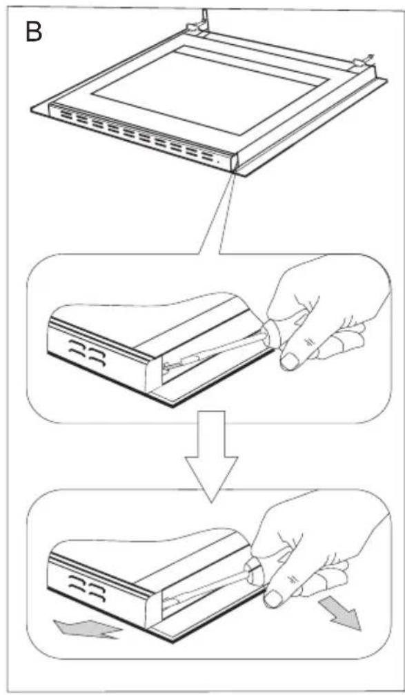
Using a flat screwdriver unhook the upper door slat, prying it gently on the sides (fig. B).
-
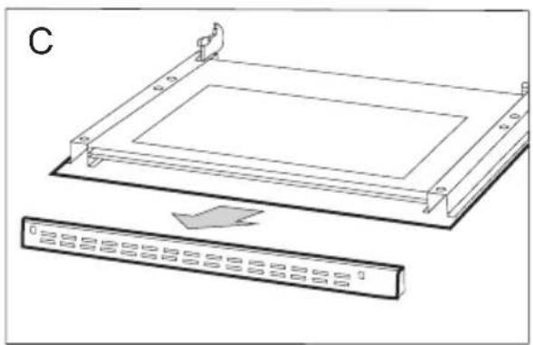
Pull the upper door slat loose. (fig. B, C)
natural_image
Technical line drawing of a rectangular electronic component with mounting brackets and a separate ruler below (no text or symbols)- Pull the inner glass panel from its seat (in the lower section of the door). Remove the inner panel (fig. D,D1).
- Clean the panel with warm water with some cleaning agent added.
Carry out the same in reverse order to reassemble the inner glass panel. Its smooth surface shall be pointed upwards.
Important! Do not force the upper strip in on both sides of the door at the same time. In order to correctly fit the top door strip, first put the left end of the strip on the door and then press the right end in until you hear a "click". Then press the left end in until you hear a "click".
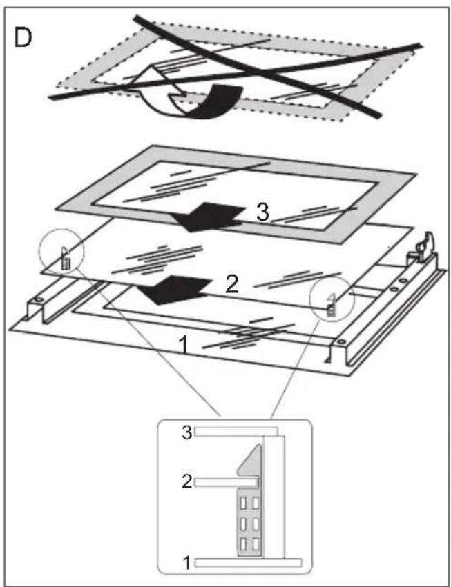
Removal of the internal glass panel 3 glass
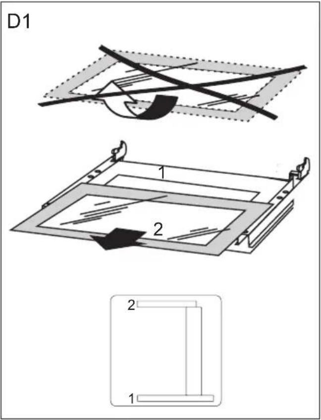
Removal of the internal glass panel 2 glass
Replacing the halogen bulb in the oven
Before replacing the halogen bulb, make sure the appliance is disconnected from the electric mains to avoid a possible electric shock.
- Unplug the appliance
- Remove shelves and trays from the oven.
- Unscrew and wash the lamp cover and then wipe it dry.
- Pull the halogen bulb out using a cloth or paper. If necessary, replace the halogen bulb with a new one.
- voltage 230V
- power 25W
- Replace the halogen bulb in its socket.
- Screw in the lamp cover.
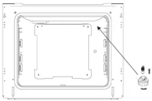
natural_image
Technical line drawing of a rectangular electronic device casing with internal components and a small component at the bottom (no text or symbols)Oven lighting
Note: Make sure not to touch the halogen directly with your fingers!
Regular inspections
Besides keeping the cooker clean, you should:
● carry out periodic inspections of the control elements and cooking units of the cooker. After the guarantee has expired you should have a technical inspection of the cooker carried out at a service centre at least once every two years,
- fix any operational faults,
● carry out periodical maintenance of the cooking units of the cooker.
Caution!
All repairs and regulatory activities should be carried out by the appropriate service centre or by an appropriately authorised fitter.
In the event of an emergency, you should:
- switch off all working units of the cooker
- disconnect the mains plug
- call the service centre
- some minor faults can be fixed by referring to the instructions given in the table below. Before calling the customer support centre or the GRAM service centre check the following points that are presented in the table.
| PROBLEM | REASON ACTION | |
| 1.The appliance does not work. break in power supply check the ho | usehold fuse box,if there is a blown fuse replaceit with a new one | |
| 2.The programmer display shows “0.00”. | the appliance was disconnected from the mains or there was a temporary power cut. | Set the current time(see ‘Use of the programmer’). |
| 3. The oven lighting does not work | the bulb is loose or damaged tigh | ten up or replace the blown bulb (see Chapter Cleaning and Maintenance) |
| 4.A single cooking zone switches off and residual heat indicator „H” is shown. | limited cook time - switch on the co | oking zone again |
| 5. Residual heat indicator extin-guished even though the cooking zones are hot | a power outage or the applian-ce has been disconnected | residual heat indicator will be shown again the next time the appliance is turned on and off again |
| 6. Induction hob makes buzzing sound. | this is normal. Cooling fan is operating to cool down internal electronics | |
| 7. Induction hob makes hissing and whistling sounds | This is normal. When using several cooking zones at full power, the hob makes hissing and whistling sounds due to the frequencies used to power the coils | |
| 8. Hob cooking surface is crac-ked. | Danger! Immediately unplug the appliance or switch off the main circuit breaker. Refer the repair to the nearest service centre. | |
| 9.When the problem is still not remedied. | Immediately unplug the appliance or switch off the main circuit breaker (fuse). Refer the repair to the nearest service centre.Important!You are responsible for operating the appliance correctly and maintaining its good condition. If you call service as a result of operating the appliance incorrectly you will be responsible for the costs incurred even under warranty.The manufacturer shall not be held liable for damage caused by failure to follow this manual. | |
| 10. E2 symbol displayed Induction coil overheated insufficient cooling, check if cookware complies,with requirements listed. | ||
Voltage rating
400V 3N\~50Hz / 400V 2N\~50Hz
Power rating max. 10,5 kW
Cooker dimensions H/W/D 60 / 50 / 85 cm
The product meets the requirements of European standards EN 60335-1; EN60335-2-6.

natural_image
Blank white image with no visible content, text, or symbols- GERBIAMAS PIRKĖJAU,
- Valdymo skydas
- GALIMU JUNGIMU SCHEMA
- Indu charakteristika.
- Dėmių šalinimas
- Dèmesio!
- VIRYKLÈS VALYMAS IR PRIEŽIŪRA
- Pliidi paigaldamine
- ELEKTRIÜHENDUSTE SKEEM
- Nõude iseloomustus.
- Ukse äravõtmine
- IESPËJAMO PIESLËGUMU SHËMA
- VIRTUVES PLİTS TİRİŞANA UN KOPŞANA
- Durvju noņemšana
- Caution!
- SAFETY INSTRUCTIONS
- DESCRIPTION OF THE APPLIANCE
- Control Panel
- Installing the cooker
- Mounting the overturning prevention bracket.
- Electrical connection
- Warning!
- Fitting guidelines
- Connection diagram
- Before using the oven for the first time
- Important!
- Electronic timer
- Set current time
- Note:
- Minute Minder
- Note!
- Timed operation
- Cancel settings
- Change the beep tone
- Adjust display brightness
- Night Mode
- Meat Probe
- Before using the appliance for the first time
- Induction cooking zone operation principle
- The protective device:
- Pan detector
- Pan detector does not operate as the on/off sensor.
- Select cookware for induction cooking
- Cookware characteristics.
- Cookware size.
- Switch on the appliance
- Switch on the cooking zone
- Selecting the cooking zone heat setting
- Switch off cooking zones
- Switch off the appliance
- Booster function "P"
- Booster function control
- The child lock function
- Turn Child Lock on/off
- Residual heat indicator
- Limiting the operating time
- Automatic warm-up function
- Timer
- Set the Timer
- Change Timer Duration
- Check Timer Duration
- OPERATION
- Stop the Timer
- Kitchen Timer
- Set Kitchen Timer
- Stop Kitchen Timer
- Keeping food warm
- Oven functions and operation.
- Oven with automatic air circulation (including a fan and ring heater)
- Oven is off
- Rapid Preheating
- Defrosting
- Fan and combined grill on
- Enhanced roaster (super roaster)
- Roaster on.
- Bottom heater on
- Top and bottom heaters on
- Convection with ring heating element
- Top heater, bottom heater and fan are on.
- Convection with ring heating element and bottom heater on
- Use of the grill
- BAKING IN THE OVEN – PRACTICAL HINTS
- Baking
- Roasting meat
- Oven
- - Steam Cleaning function:
- Wire shelf supports
- Door removal
- Removing the inner panel
- Replacing the halogen bulb in the oven
- Before replacing the halogen bulb, make sure the appliance is disconnected from the electric mains to avoid a possible electric shock.
- Regular inspections
Brand : Hansa
Model : FCIW59209
Category : Cooker