
MS15SA - Loudspeaker ALTO - Free user manual and instructions
Find the device manual for free MS15SA ALTO in PDF.


| Product Type | Portable Bluetooth Speaker |
| Model | MS15SA |
| Brand | Alto |
| Dimensions | Approx. 18 x 8 x 8 cm |
| Weight | Approx. 0.5 kg |
| Power Source | Built-in rechargeable battery, USB-C charging |
| Battery Life | Up to 10 hours |
| Connectivity | Bluetooth 5.0, 3.5mm AUX input |
| Wireless Range | Up to 10 meters |
| Speaker Output | 10W RMS |
| Frequency Response | 80Hz - 20kHz |
| Controls | Buttons for power, volume, play/pause, Bluetooth pairing |
| Microphone | Built-in for hands-free calling |
| Water Resistance | IPX4 (splash-proof) |
| Compatible Devices | Smartphones, tablets, laptops |
| Box Contents | Speaker, USB-C cable, AUX cable, user manual |
| Cleaning | Wipe with dry cloth, avoid liquids |
| Battery Charging Time | Approx. 3 hours |
Frequently Asked Questions - MS15SA ALTO
User questions about MS15SA ALTO
0 question about this device. Answer the ones you know or ask your own.
Ask a new question about this device
Download the instructions for your Loudspeaker in PDF format for free! Find your manual MS15SA - ALTO and take your electronic device back in hand. On this page are published all the documents necessary for the use of your device. MS15SA by ALTO.
USER MANUAL MS15SA ALTO
natural_image
Close-up of a speaker grille with visible sound waves and a triangular warning symbol (no text or labels)www.altoproaudio.com Version 2.0 SEPTEMBER 2007
English

CAUTION
RISK OF ELECTRIC SHOCK DO NOT OPEN

TO REDUCE THE RISK OF ELECTRIC SHOCK PLEASE DO NOT REMOVE THE COVER OR THE BACK PANEL OF THIS EQUIPMENT. THERE ARE NO PARTS NEEDED BY USER INSIDE THE EQUIPMENT. FOR SERVICE, PLEASE CONTACT QUALIFIED SERVICE CENTERS.
This symbol, wherever used, alerts you to the presence of un-insulated and dangerous voltages within the product enclosure. These are voltages that may be sufficient to constitute the risk of electric shock or death.
This symbol, wherever used, alerts you to important operating and maintenance instructions. Please read.
⊕ Protective Ground Terminal \~ AC mains (Alternating Current) ‡ Hazardous Live Terminal
ON: Denotes the product is turned on. OFF: Denotes the product is turned off.
CAUTION
Describes precautions that should be observed to prevent damage to the product.
-
Read this Manual carefully before operation.
-
Keep this Manual in a safe place.
-
Be aware of all warnings reported with this symbol.
-
Keep this Equipment away from water and moisture.
-
Clean it only with dry cloth. Do not use solvent or other chemicals.
-
Do not damp or cover any cooling opening. Install the equipment only in accordance with the Manufacturer's instructions.
-
Power Cords are designed for your safety. Do not remove Ground connections! If the plug does not fit your AC outlet, seek advice from a qualified electrician. Protect the power cord and plug from any physical stress to avoid risk of electric shock. Do not place heavy objects on the power cord. This could cause electric shock or fire.
-
Unplug this equipment when unused for long periods of time or during a storm.
-
Refer all service to qualified service personnel only. Do not perform any servicing other than those instructions contained within the User's Manual.
-
To prevent fire and damage to the product, use only the recommended fuse type as indicated in this manual. Do not short-circuit the fuse holder. Before replacing the fuse, make sure that the product is OFF and disconnected from the AC outlet.
WARNING
To reduce the risk of electric shock and fire, do not expose this equipment to moisture or rain.

Dispose of this product should not be placed in municipal waste and should be separate collection.
- Move this Equipment only with a cart, stand, tripod, or bracket.
specified by the manufacturer, or sold with the Equipment. When a cart is used, use caution when moving the cart / equipment combination to avoid possible injury from tip-over.

natural_image
Abstract black-and-white icon of a person pushing a large rectangular block, enclosed in a circular frame (no text or symbols)- Permanent hearing loss may be caused by exposure to \ extremely high noise levels. The US. Government's Occupational Safety and Health Administration (OSHA) has specified the permissible exposure to noise level.
These are shown in the following chart:
| HOURS X DAY | SPL | EXAMPLE |
| 8 | 90 | Small gig |
| 6 | 92 | train |
| 4 | 95 | Subway train |
| 3 | 97 | High level desktop monitors |
| 2 | 100 | Classic music concert |
| 1,5 | 102 | |
| 1 | 105 | |
| 0,5 | 110 |
0,25 or less 115 Rock concert
According to OSHA, an exposure to high SPL in excess of these limits may result in the loss of heat. To avoid the potential damage of heat, it is recommended that Personnel exposed to equipment capable of generating high SPL use hearing protection while such equipment is under operation.
The apparatus shall be connected to a mains socket outlet with a protective earthing connection.
The mains plug or an appliance coupler is used as the disconnect device, the disconnect device shall remain readily operable.
IN THIS MANUAL:
- INTRODUCTION....1
- QUICK START - PASSIVE SPEAKER CABINET....2
- PANEL DESCRIPTION....7
- WIRE CONNECTIONS....8
- FREQUENCY RESPONSE DIAGRAM....9
- TECHNICAL SPECIFICATION....11
- WARRANTY....13
1. INTRODUCTION
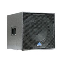
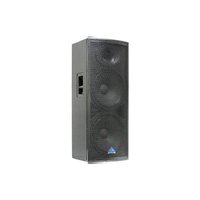
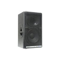
Thank you very much for expressing your confidence in ▲LTO products by purchasing MS series powered speaker system. The MS series cabinets are specifically designed for using in hi-quality performance site and the precise sound commercial place. It includes five full range cabinets (MS12A, MS15A, MS152A, MS153A, and MS154A). This series uses trapezium configuration which greatly decreases the resonance of the standing wave in the cabinet. These cabinets uses hi-density matrix spray-paint technics and the bottom bracket design which make mounting quickly and Flexibly. The HF compression driver and vented LF for fully professional performance.
The MS powered speaker cabinets include some exclusive innovations such as switch mode power supply and digital power circuitry (in selected modes) that make them the lightest powered cabinets of this kind ever made. The MS full range models include another Alto innovation: The MODELLER. Thanks to this circuitry, users can select 16 different tastes and applications. The 16 kinds of sound presets especially thought for application with or without subwoofer, for voice optimized application, for Disco Music, for Jazz, for Rock & Roll among others.
Enjoy your MS active speaker cabinet and make sure to read this Manual carefully before operation!
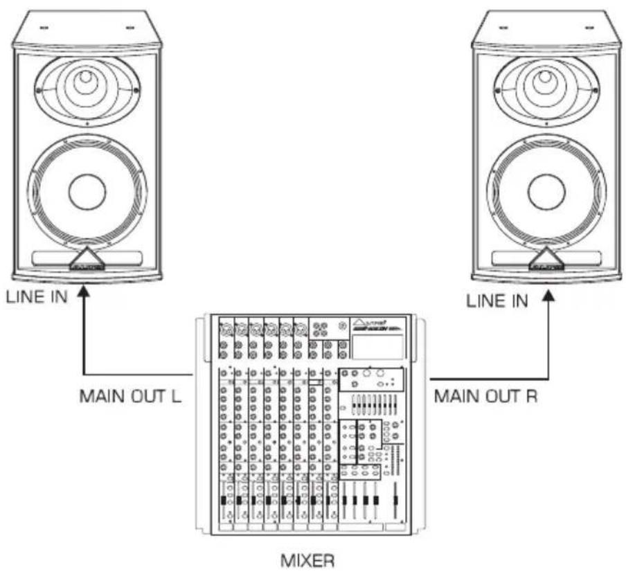
Active, Full-range, two speakers. This is the simplest set-up. You do not need a power amplifier in between the mixer and the 2 MS speakers.
Make all initial connections with all the equipment powered off, and ensure that all the main volume controls are turned down completely.
1). Connect one side of the signal cable at your mixer into the Main Output Left /Right (with 1/4"Jack or XLR) and the other side of the cable in to the Line Input (COMBO) of your MS active speaker cabinet (with 1/4"Jack or XLR).
2). Connect the power cord to mains.
3). Turn ON your mixer first, then the MS cabinets.
4). Turn up the volume control of the MS cabinets.
5). Use PFL function to get the proper input level for the mixer, and adjust the Main Mix Level control to reach the desired output level.
6). After use, turn off your active speaker cabinets first, then the mixer.

2. QUICK START - ACTIVE SPEAKER CABINETS
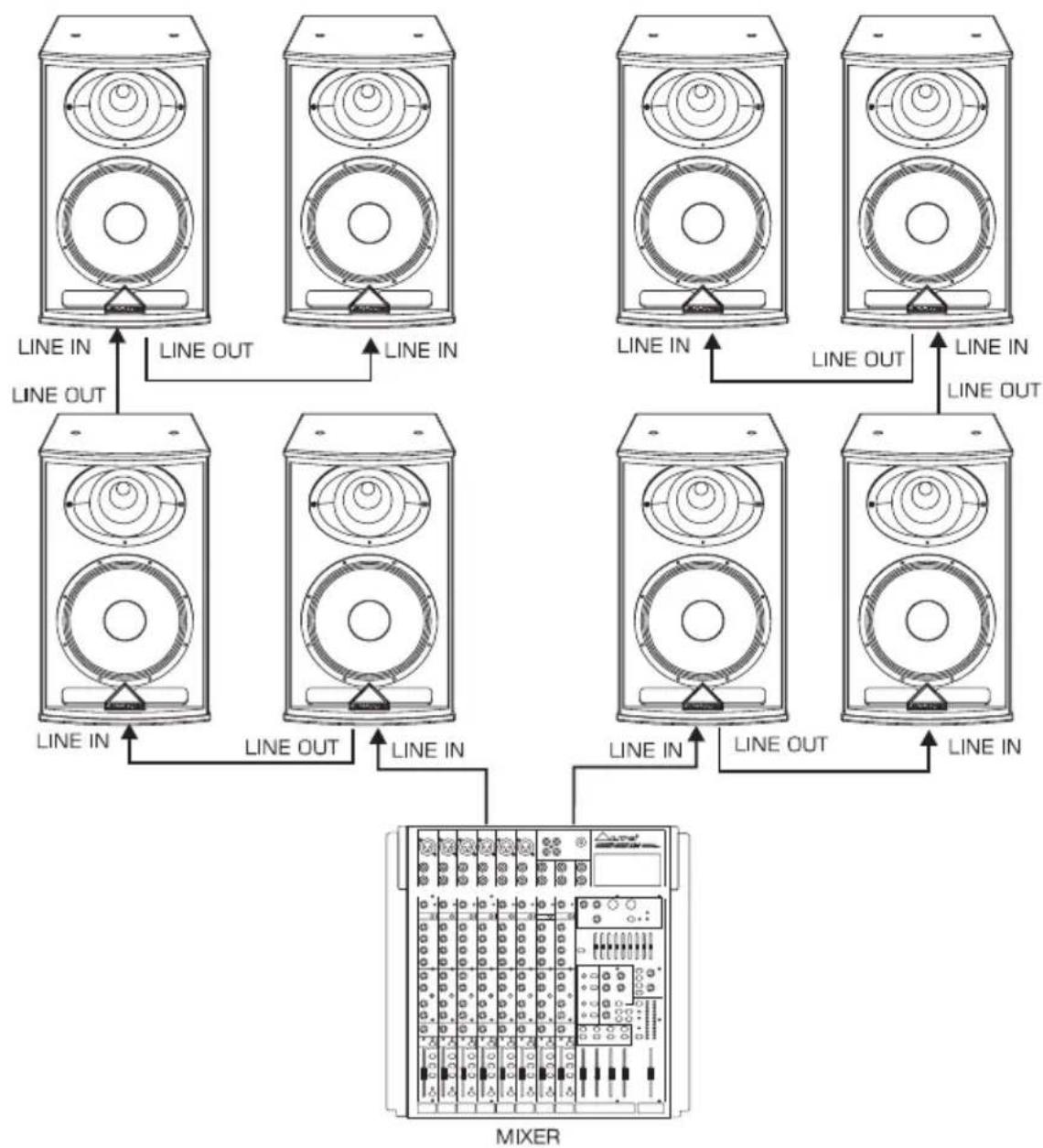
Active, Full-range, multiple speakers. This solution is particularly flexible when you have a large stage and for fixed installations where you want to send the same signal to different zones like in a Bar, Pub, Restaurant, Church, etc. Each MS cabinet has its own volume control so you can adjust different volumes in different zones.
1). Follow the above steps connecting the MAIN OUTPUTS of the mixer to the LINE INPUTS of 2 MS active cabinets.
2). Connect the LINE OUT socket of the first MS cabinet to the LINE IN socket of the subsequent piece. You can connect as many speakers as you wish in this way.
flowchart
graph TD
    A["Speaker 1"] -->|LINE IN| B["Mixer"]
    C["Speaker 2"] -->|LINE OUT| B
    D["Speaker 3"] -->|LINE IN| B
    E["Speaker 4"] -->|LINE IN| B
    F["Speaker 5"] -->|LINE OUT| B
    G["Speaker 6"] -->|LINE IN| B
    H["Speaker 7"] -->|LINE OUT| B
    I["Speaker 8"] -->|LINE IN| B
    J["Speaker 9"] -->|LINE OUT| B
    K["Speaker 10"] -->|LINE IN| B
    L["Speaker 11"] -->|LINE OUT| B
    M["Speaker 12"] -->|LINE IN| B
    N["Speaker 13"] -->|LINE OUT| B
    O["Speaker 14"] -->|LINE IN| B
    P["Speaker 15"] -->|LINE OUT| B
    Q["Speaker 16"] -->|LINE IN| B
    R["Speaker 17"] -->|LINE OUT| B
    S["Speaker 18"] -->|LINE IN| B
    T["Speaker 19"] -->|LINE OUT| B
    U["Speaker 20"] -->|LINE IN| B
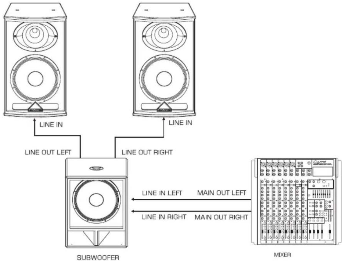
Active, two satellite speakers & two subwoofers. In this example the mixer is connected to the subwoofers and then a line signal is sent to the respective satellites. In this way, the high energetic content of the low frequencies is limited to the subwoofer and the satellite's woofer act like a mid-woofer. As a consequence the satellites built-in amplifier is not stressed by low frequency content.
1). Connect one side of signal cable at your mixer into Main Output Left/Right (with 1/4" Jack or XLR) and the other side of the cable into the Left/Mono Input (COMBO) of the active subwoofers; with the second signal cable connect the Left/Mono Line Output of the subwoofer (Stereo/Mono-Jack or XLR) to the Line input (COMBO) of the active satellite (with Stereo - Jack or XLR).
2). Connect the power cord to mains.
3). Turn on your mixer first, then the active speaker cabinets.
4). Turn up the volume control of the active speaker cabinets.
5). Use PFL function to get the proper input level for the mixer, and adjust the Main Mix Level control to manipulate the output level.
6). After use, turn off your active speaker cabinets first, then the mixer.

flowchart
graph TD
    A["SubWOOFER"] -->|LINE IN\nLINE OUT LEFT/MONO| B["Mixer"]
    C["SubWOOFER"] -->|LINE IN\nLINE OUT LEFT/MONO| B["Mixer"]
    B -->|MAIN OUT LEFT\nLINE IN LEFT/MONO| D["Mixer"]
    B -->|MAIN OUT RIGHT\nLINE IN LEFT/MONO| E["SubWOOFER"]
Active, two satellite speakers and one subwoofers.
This is a very popular combination, especially in small size clubs where there is no need for two subwoofers.
1). Connect one side of signal cable at your mixer into Main Output Left (with 1/4"Jack or XLR) and the other side of the cable into the Left Input of the active subwoofer. Repeat for the RIGHT channel. With the second signal cable connect the Left Line Output of the subwoofer (Stereo/Mono-Jack or XLR) to the Line input (COMBO) of the active satellite (with Stereo-Jack or XLR). Repeat for the RIGHT channel
2). Connect the power cord to mains.
3). Turn on your mixer first, then the active speaker cabinets.
4). Turn up the volume control of the active speaker cabinets.
5). Use PFL function to get the proper input level for the mixer, and adjust the Main Mix Level control to manipulate the output level.
6). After use, turn off your active speaker cabinets first, then the mixer.
Active, with Microphone and Line Level instruments.
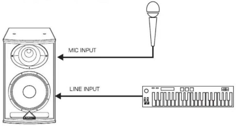
Your Elvis cabinets come with both Line-level and with Microphone Inputs. You can directly connect a microphone into your Elvis cabinet using the MIC input and a keyboard or an electric guitar (you must interconnect a D/I Box if you want to use the guitar) and use the relative level controls as a simple mixer. You can then use the resident 3-bands graphic equalizer to fine-tune your sound. This configuration is good for presentation, meetings, aerobic centers and fashion shows (you can also connect a wireless microphone into the Line input, or for "One Man band" performances.)
ACTIVE FULL-RANGE: MS12A/MS15A/MS152A/MS153A/MS154A
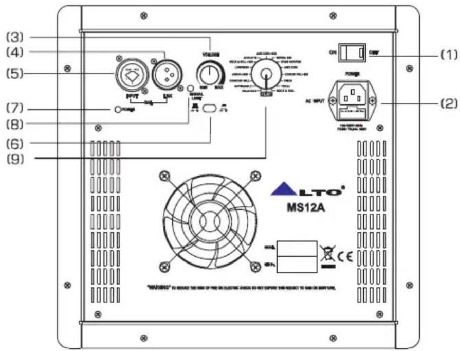
(1) ON-OFF main power switch
(2) Input AC power socket with main fuse
(3) VOLUME main power amplifier control
(4) LINE OUT at + 4dB on XLR connector
(5) LINE IN at + 4dB on COMBO connector
(6) Ground Lift Switch
(7) POWER, Green LED, indicate ON status
(8) SIGNAL/LIMIT, Red LED, indicate ON status
(9) Presets Selector
Via this knob, you can select the right effect you wish to perform. There are total 16 options for you, JAZZ CLUB+SUB, VIRTUAL SUB, STAGE MONITOR, JAZZ CLUB, CONCERT HALL+SUB, DISCO, VOCAL, ROCK & ROLL, FLAT, DRUM KICK, ANTIRUMBLE, CONCERT HALL, ARENA+SUB, LOUDNESS, ROCK & ROLL+SUB and ACOUSTIC.
-. For Active Speaker Cabinets
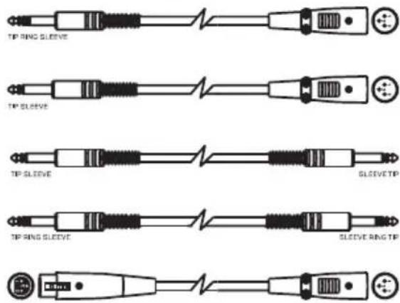
As to these circumstances, audio connections is mostly intended for the signal flow, so, determine the wire configuration according to your real application system and its connecting facility. Normally, you have the following choices:
• Balanced


flowchart
graph TD
    A["Tip"] --> B["Ring"]
    C["Tip"] --> D["Sleeve"]
    E["Ring"] --> F["Sleeve"]
    G["Ring"] --> H["Sleeve"]
    I["1"] --> J["2"]
    K["1"] --> L["3"]
    M["1"] --> N["2"]
    O["2"] --> P["3"]
    Q["2"] --> R["3"]
    S["3"] --> T["3"]
- Unbalanced

flowchart
graph TD
    A["Tip"] --> B["Ring"]
    B --> C["Sleeve"]
    D["Tip"] --> E["Ring"]
    E --> F["Sleeve"]
    G["Tip"] --> H["Sleeve"]
    I["Tip"] --> J["Sleeve"]
    K["1"] --> L["2"]
    M["1"] --> N["2"]
    O["1"] --> P["3"]
    Q["1"] --> R["2"]
    S["1"] --> T["3"]
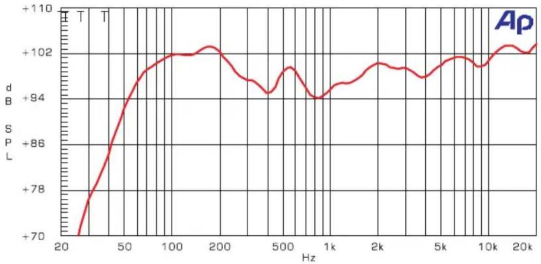
5. FREQUENCY RESPONSE
MS152A
line
| Hz | d B | | ---- | ----- | | 20 | +70 | | 50 | +86 | | 100 | +102 | | 200 | +102 | | 500 | +94 | | 1k | +94 | | 2k | +102 | | 5k | +102 | | 10k | +102 | | 20k | +102 |MS153A

line
| Hz | d | | ---- | ----- | | 20 | +70 | | 50 | +85 | | 100 | +95 | | 200 | +105 | | 500 | +95 | | 1k | +100 | | 2k | +95 | | 5k | +100 | | 10k | +95 | | 20k | +105 |MS154A
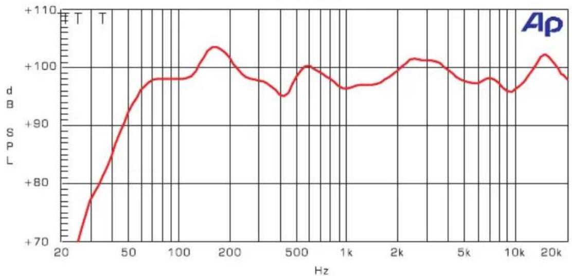
line
| Hz | Power (dB) | | ---- | ---------- | | 20 | +70 | | 50 | +90 | | 100 | +100 | | 200 | +105 | | 500 | +95 | | 1k | +100 | | 2k | +102 | | 5k | +98 | | 10k | +96 | | 20k | +103 |MS12A

line
| Hz | d B | | ---- | ----- | | 20 | +70 | | 50 | +90 | | 100 | +95 | | 200 | +95 | | 500 | +100 | | 1k | +95 | | 2k | +95 | | 5k | +95 | | 10k | +95 | | 20k | +85 |MS15A

line
| Hz | dB | | ---- | ----- | | 20 | +70 | | 50 | +90 | | 100 | +98 | | 200 | +102 | | 500 | +100 | | 1k | +98 | | 2k | +100 | | 5k | +98 | | 10k | +96 | | 20k | +90 |6. TECHNICAL SPECIFICATION
| Model Item | MS12A |
| Active System Type | 2-Way Bi-Amp. with MODELLER |
| Low Output Power | 350 Watt EIAJ |
| High Output Power | 65 Watt EIAJ |
| Max SPL 1mt | 122 dB SPL calculated EIAJ |
| Frequency Response | MODELLER Presets Setting |
| Protection Low - High | Analog Limiter |
| Input Impedance | 30 kΩ Balanced/15 kΩ Unbalanced |
| Input Sensitivity | Line +4 dB |
| Low Frequency Device | 12" Woofer/2" Voice Coil |
| High Frequency Device | 1" Neodymium Driver/1" Voice Coil |
| Coverage( H' x V') | 90° H x 60° V Elliptical Wave Guide |
| Connectors | Input with Combo/Link with XLR |
| Cabinet | Trapezoidal Shape/Composite Wood/Metal Handle/Black Paint Finishing |
| External Control | MODELLER with 16 Preset/Line Volume/Clipping LED Indicator/Ground Switch |
| Dimensions( H x W x D) | 650 x 400 x 365 (mm) |
| Net Weight (lbs/kg) | 48.50 lbs/22 kg |
| Model Item | MS15A |
| Active System Type | 2-way Bi-Amp. with MODELLER |
| Low Output Power | 350 Watt EIAJ |
| High Output Power | 65 Watt EIAJ |
| Max SPL 1mt | 123 dB SPL Calculated EIAJ |
| Frequency Response | MODELLER Presets Setting |
| Protection Low - High | Analog Limiter |
| Input Impedance | 30 kΩ Balanced/15 kΩ Unbalanced |
| Input Sensitivity | Line +4 dB |
| Low Frequency Device | 15" woofer/2.5" Voice Coil |
| High Frequency Device | 1" Neodymium Driver/1" Voice Coil |
| Coverage( H' x V') | 90° H x 60° V Elliptical Wave Guide |
| Connectors | Input with Combo/Link with XLR |
| Cabinet | Trapezoidal Shape/Composite Wood/Metal Handle/Black Paint Finishing |
| External Control | MODELLER with 16 Preset/line Volume/Clipping LED Indicator/Ground Switch |
| Dimensions( H x W x D) | 750 x 450 x 420 (mm) |
| Net Weight (lbs/kg) | 59.52 lbs/27 kg |
| Model Item | MS152A |
| Active System Type | 2-way Bi-Amp. with MODELLER |
| Low Output Power | 350 Watt EIAJ |
| High Output Power | 65 Watt EIAJ |
| Max SPL 1mt | 126 dB SPL Calculated EIAJ |
| Frequency Response | MODELLER Presets Setting |
| Protection Low - High | Analog Limiter |
| Input Impedance | 30 kΩ Balanced/15 kΩ Unbalanced |
| Input Sensitivity | Line +4 dB |
| Low Frequency Device | 2 x 15" Woofer/2.5" Voice Coil |
| High Frequency Device | 1" Driver/1.35" Voice Coil |
| Coverage( H' x V') | 90° H x 60° V Elliptical Wave Guide |
| Connectors | Input with Combo/Link with XLR |
| Cabinet | Trapezoidal Shape/Multi-layer Plywood/Metal Handle/Black Paint Finishing |
| External Control | MODELLER with 16 Preset/line Volume/Clipping LED Indicator/Ground Switch |
| Dimensions( H x W x D) | 1100 x 450 x 443 (mm) |
| Net Weight (lbs/kg) | 83.29 lbs/37.78 kg |
6. TECHNICAL SPECIFICATION
| Model Item | MS153A |
| Active System Type | 3-Way Bi-Amp. with MODELLER |
| Low Output Power | 500 Watt EIAJ |
| High Output Power | 500 Watt EIAJ |
| Max SPL 1mt | 127 dB SPL Calculated EIAJ |
| Frequency Response | MODELLER Presets Setting |
| Protection Low - High | Analog Limiter |
| Input Impedance | 30 kΩ Balanced/15 kΩ Unbalanced |
| Input Sensitivity | Line: +4 dB |
| Low Frequency Device | 15" Woofer/2.5" Voice Coil |
| Mid Frequency Device | 8" Midrange/2" Voice Coil |
| High Frequency Device | 1" Driver/1.35" Voice Coil |
| Coverage( H° x V°) | 90° H x 45° V Dual Wave Guide |
| Connectors | Input with Combo/Link with XLR |
| Cabinet | Trapezoidal Shape/Multi-layer Plywood/Metal Handle/Black Paint Finishing |
| External Control | MODELLER with 16-Preset/Line Volume/Clipping LED Indicator /Ground Switch |
| Dimensions( H x W x D) | 900 x 450 x 415 (mm) |
| Net Weight (lbs/kg) | 72.22 lbs/32.76 kg |
| Model Item | MS154A |
| Active System Type | 3-Way Bi-Amp. with MODELLER |
| Low Output Power | 750 Watt EIAJ |
| High Output Power | 750 Watt EIAJ |
| Max SPL 1mt | 131 dB SPL Calculated EIAJ |
| Frequency Response | MODELLER Presets Setting |
| Protection Low - High | Analog Limiter |
| Input Impedance | 30 kΩ Balanced/15 kΩ Unbalanced |
| Input Sensitivity | Mic: -45 dB Line: +4 dB |
| Low Frequency Device | 2x15" woofer/2.5" Voice Coil |
| Mid Frequency Device | 8" Midrange/ 2" Voice Coil |
| High Frequency Device | 1"Driver/1.35" Voice Coil |
| Coverage( H° x V°) | 90° H x 45° V Dual Wave Guide |
| Connectors | Input with Combo/Link with XLR |
| Cabinet | Trapezoidal Shape/Multi-layer Plywood/Metal Handle/Black Paint Finishing |
| External Control | MODELLER with 16 Preset/Line Volume/Clipping LED Indicator / Ground Switch |
| Dimensions( H x W x D) | 1250 x 450 x 443 (mm) |
| Net Weight (lbs/kg) | 99.85 lbs/45.29 kg |
7. WARRANTY
1. WARRANTY REGISTRATION CARD
To obtain Warranty Service, the buyer should first fill out and return the enclosed Warranty Registration Card within 10 days of the Purchase Date.
All the information presented in this Warranty Registration Card gives the manufacturer a better understanding of the sales status, so as to provide a more effective and efficient after-sales warranty service. Please fill out all the information carefully and genuinely, miswriting or absence of this card will void your warranty service.
2. RETURN NOTICE
2.1 In case of return for any warranty service, please make sure that the product is well packed in its original shipping carton, and it can protect your unit from any other extra damage.
2.2 Please provide a copy of your sales receipt or other proof of purchase with the returned machine, and give detail information about your return address and contact telephone number.
2.3 A brief description of the defect will be appreciated.
2.4 Please prepay all the costs involved in the return shipping, handling and insurance.
3. TERMS AND CONDITIONS
3.1 ▲LTO warrants that this product will be free from any defects in materials and/or workmanship for a period of 1 year from the purchase date if you have completed the Warranty Registration Card in time.
3.2 The warranty service is only available to the original consumer, who purchased this product directly from the retail dealer, and it can not be transferred.
3.3 During the warranty service, ▲LTO may repair or replace this product at its own option at no charge to you for parts or for labor in accordance with the right side of this limited warranty.
3.4 This warranty does not apply to the damages to this product that occurred as the following conditions:
- Instead of operating in accordance with the user's manual thoroughly, any abuse or misuse of this product.
• Normal tear and wear
• The product has been altered or modified in any way. - Damage which may have been caused either directly or indirectly by another product / force / etc.
- Abnormal service or repairing by anyone other than the qualified personnel or technician.
And in such cases, all the expenses will be charged to the buyer.
3.5 In no event shall ▲LTO be liable for any incidental or consequential damages. Some states do not allow the exclusion or limitation of incidental or consequential damages, so the above exclusion or limitation may not apply to you.
3.6 This warranty gives you the specific rights, and these rights are compatible with the state laws, you may also have other statutory rights that may vary from state to state.
SEIKAKU TECHNICAL GROUP LIMITED
NO. 1, Lane 17, Sec. 2, Han Shi West Road, Taichung 40151, Taiwan
http://www.altoproaudio.com Tel: 886-4-22313737
email: alto@altoproaudio.com Fax: 886-4-22346757
All rights reserved to ALTO. All features and content might be changed without prior notice. Any photocopy, translation, or reproduction of part of this manual without written permission is forbidden. Copyright 2007 Seikaku Group
- CAUTION
- WARNING
- IN THIS MANUAL:
- INTRODUCTION
- QUICK START - ACTIVE SPEAKER CABINETS
- Active, with Microphone and Line Level instruments.
- ACTIVE FULL-RANGE: MS12A/MS15A/MS152A/MS153A/MS154A
- -. For Active Speaker Cabinets
- • Balanced
- - Unbalanced
- FREQUENCY RESPONSE
- TECHNICAL SPECIFICATION
- WARRANTY
- WARRANTY REGISTRATION CARD
- RETURN NOTICE
- TERMS AND CONDITIONS
- SEIKAKU TECHNICAL GROUP LIMITED
Brand : ALTO
Model : MS15SA
Category : Loudspeaker