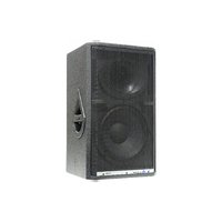
SR400A - Loudspeaker ALTO - Free user manual and instructions
Find the device manual for free SR400A ALTO in PDF.


| Product Type | Active Full-range Speaker |
| Model | Alto SR400A |
| Amplifier Type | Bi-amped with DSP Processor |
| Low-frequency Driver | 15" (385mm) with 3" voice coil |
| High-frequency Driver | 1.35" Compression Driver |
| Horn Coverage | 90° Horizontal x 60° Vertical |
| System Peak Power | 1000W Peak |
| Max SPL at 1m | 124dB (calculated) |
| Frequency Response | 50Hz - 20kHz (-10dB) |
| Crossover Frequency | 2000Hz (DSP controlled) |
| Low-frequency Amplifier Power | 232W RMS @ 8Ω, 382W RMS @ 4Ω (Class H) |
| High-frequency Amplifier Power | 232W RMS @ 8Ω, 382W RMS @ 4Ω (Class AB) |
| Input Sensitivity | Mic/Line: +4dBu / 1.23V |
| Input Impedance | 30 kΩ Balanced, 15 kΩ Unbalanced |
| Connectors | Combo (XLR/TRS) Input, XLR Link Output |
| Preset Control | 16 DSP Presets (e.g., Concert Hall, Live, Flat, Vocal, etc.) |
| Protections | Soft Start, Short Circuit, DC Voltage, Thermal Protection |
| Cabinet Material | 18mm Multilayer Plywood |
| Suspension Points | 5 x M10 (30mm depth) for flying |
| Power Supply | 115V/230V, 50/60Hz (selectable) |
| Dimensions (H x W x D) | 680 x 455 x 440 mm (26.8 x 17.9 x 17.3 in) |
| Net Weight | Approx. 33 kg (72.8 lbs) |
| Cleaning Instructions | Wipe with a dry cloth; do not use liquids or solvents. |
| Safety Notes | Read manual before use; avoid water, heat, and liquid entry. |
Frequently Asked Questions - SR400A ALTO
User questions about SR400A ALTO
0 question about this device. Answer the ones you know or ask your own.
Ask a new question about this device
Download the instructions for your Loudspeaker in PDF format for free! Find your manual SR400A - ALTO and take your electronic device back in hand. On this page are published all the documents necessary for the use of your device. SR400A by ALTO.
USER MANUAL SR400A ALTO
natural_image
Close-up of a black mesh-mounted speaker grille with visible sound waves and a logo (no readable text or symbols)
www.altoproaudio.com
Version 1.3 August 2006
— English English

▲"Electric discharge"
This symbol, alert you to the presence of uninsulated dangerous voltage inside the product enclosure, which constitutes a risk of electric shock.
▲"Exclamatory point"
This symbol, alert the user to the presence of important operating and maintenance instructions in the owner's manual included to the product.

Disposing of this product should not be placed in municipal waste and should be Separate collection.
1. Read Instructions
All the safety and operation instructions should be read before using the product and retain them for future reference.
2. Water & Moisture
This product should not be used near water and will be protect from atmospheric agents in fixed or temporary installations.
3. Heat
This product should be situated away from heat sources such as radiators, or other devices which produce heat.
4. Liquid Entry
Care should be taken so that liquids are not spilled into the product and that objects do not fall on.
5. Service Assistance
This product should be serviced only by qualified service personnel when :
a. Liquids has spilled or objects have fallen into this product, or
b. This product has been exposed to rain, or
c. This product does not appear to operate normally or exhibits change in performance, or has been dropped or its cabinet / chassis damaged.
6. Package
The package of this product has been tested, inspect the package before open, if any damage is found, notify to your dealer.
7. Hearing
This product produce high acoustic levels may cause permanent hearing loss, (SPL in for a defined period of time).
8. Installations
This product should be installed on the floor with a specific stand, according to the max weight, or in suspension with a five points included in the cabinet (M10 × 1.5PH Length 30mm).
The suspension of more speaker cabinet in a vertical array is NOT advised.
TABLE OF CONTENT
- QUICK START - PASSIVE SPEAKER CABINET....3
-. For Passive Full-range Speakers
-. For Passive Subwoofer & Satellite Speakers
- QUICK START - ACTIVE SPEAKER CABINET....5
-. For Active Full-range Speakers
-. For Active Subwoofer & Satellite Speakers
- CONNECTION PLATE....7
-. Passive Full-range Speaker for SR300 / SR400 / SR500
-. Passive Subwoofer Speaker for SR500S
-. Active Full-range Speaker for SR300A / SR400A / SR500A
-. Active Subwoofer Speaker for SR500SA
- WIRE CONNECTIONS ....10
-. For Passive Speaker Cabinets
-. For Active Speaker Cabinets
- TECHNICAL SPECIFICATIONS ....11
1. QUICK START - PASSIVE SPEAKER CABINET
Make all initial connections with all the equipment powered off, and ensure that all the main volume controls are turned completely down.
-. For Passive Full-range Speakers
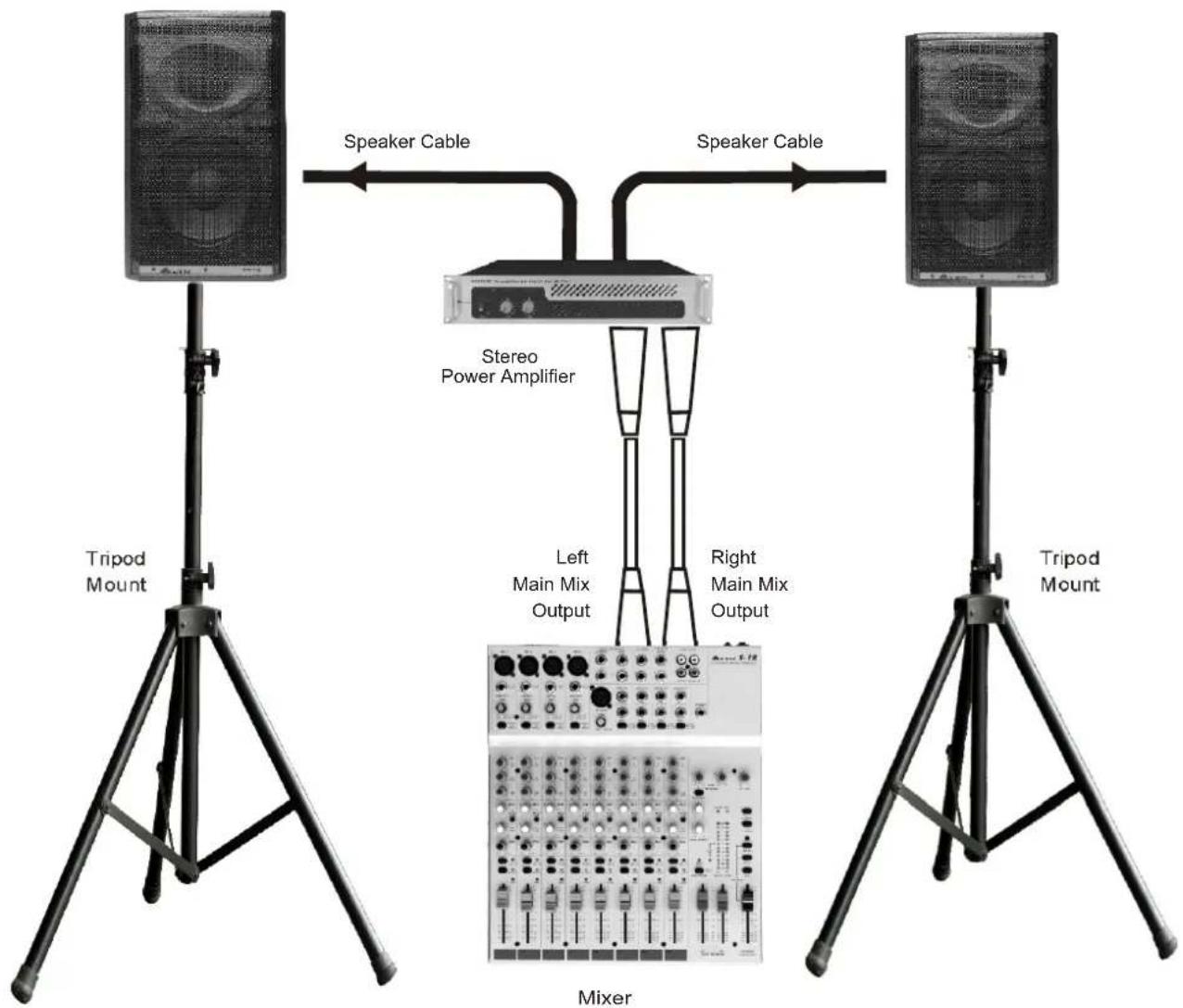
1). Connect one side of the speaker cable to the output CHA/CHB or binding post of your stereo power amplifier and the other side to the input socket of your speaker cabinet.
2). Complete other connections as illustrated.
3). Turn on your mixer first, then the stereo power amplifier.
4). Turn up the volume controls of your amplifier to about 70%.
5). Use PFL function to get the proper input level for the mixer, and adjust the main mix level control to manipulate the output level.
6). After using, turn off your stereo power amplifier first, then the mixer.
QUICK START
SR Passive Full-range Speakers
-. For Passive Subwoofer & Satellite Speakers
1). Connect one side of speaker cable to the output CHA/CHB or binding post of your stereo power amplifier and the other side to the input socket of your subwoofer, with the second speaker cable connect the output of the subwoofer to the input of satellite.
2). Complete other connections as illustrated.
3). Turn on your mixer first, then the stereo power amplifier.
4). Turn up the volume controls of your amplifier to about 70%.
5). Use PFL function to get the proper input level for the mixer, and adjust the main mix level control to manipulate the output level.
6). After using, turn off your stereo power amplifier first, then the mixer.
QUICK START
SR Passive Subwoofer & Satellite Speakers

flowchart
graph TD
    A["Speaker Cable"] -->|pole Mount| B["Speaker Cable"]
    C["Pole Mount"] -->|Speaker Cable| B
    D["Speaker Cable"] -->|pole Mount| E["Speaker Cable"]
    B --> F["Stereo Power Amplifier"]
    E --> F
    F --> G["Mixer"]
    style F fill:#f9f,stroke:#333
    note right of F Right Main Mix Output
    note left of F Left Main Mix Output
2. QUICK START - ACTIVE SPEAKER CABINET
Make all initial connections with all the equipment powered off, and ensure that all the main volume controls are turned completely down.
-. For Active Full-range Speakers
1). Connect one side of the signal cable to the output left /right (with Stereo-Jack or XLR) of your audio mixer and the other side to the line input (COMBO) of your active speaker cabinet (with Stereo-Jack or XLR).
2). Connect the power cord to mains.
3). Turn on your mixer first, then the active speaker cabinets.
4). Turn up the volume control of the active speaker cabinets.
5). The SR400A work with 16 presets, select your favorite between 1 (CONCERT - HALL), to 9 (KARAOKE), this preset included a +6dB bass boost, except the preset 3 (FLAT), 4 (VOCAL) and 8 (FLOOR MONITOR); the other presets between 10 (CONCERT H. + SW), to 16 (KARAOKE + SW), work with a natural bass response, if required from the musical program, or for improve the matching with a subwoofer SR500SA.
6). Use PFL function to get the proper input level for the mixer, and adjust the main mix level control to manipulate the output level.
7). After using, turn off your active speaker cabinets first, then the mixer.

flowchart
graph LR
    A["Tripod Mount"] -->|Signal Cable| B["Power Cord"]
    B --> C["Left Main Mix Output"]
    C --> D["Mixer"]
    D --> E["Right Main Mix Output"]
    E --> F["Signal Cable"]
    F --> G["Power Cord"]
    G --> H["Tripod Mount"]
-. For Active Subwoofer & Satellite Speakers
1). Connect one side of signal cable to output left/right of your audio mixer (with stereo-Jack or XLR) and the other side to the left/right input (stereo/mono XLR) of the active subwoofer; with the second signal cable connect the left/right output of the subwoofer (stereo/mono-XLR) to the line input (COMBO) of the active satellite (with stereo-Jack or XLR).
2). Connect the power cord to mains.
3). Turn on your mixer first, then the active speaker cabinets.
4). Turn up the volume control fo the active speaker cabinets.
5). Select one of the sixteen presets in to SR400A, with encoder knob (example: number 15 - DISCO + SW).
6). The Subwoofer SR500SA work with 16 presets, select the best crossover frequency presets between 1 (80Hz BOOST 0°) in phase or 2 (80Hz BOOST 180°) out of phase, to 9 (160Hz BOOST 0°) in phase or 10 (160Hz BOOST 180°) out of phase, this preset included a +6dB bass boost; the other presets between 11 (100Hz FLAT 0°) in phase or 12 (100Hz FLAT 180°) out of phase to 15 (140Hz FLAT 0°) in phase or 16 (140Hz FLAT 180°) out of phase, work with a Natural Bass response, if required from the musical program.
Select one of the sixteen presets in to SR500SA, with encoder knob (example: number 4 - 100Hz BOOST 180° out of phase, or the number 6 - 120Hz BOOST 180°) out of phase, for coupling to the preset 15 - DISCO + SW of the satellite. The selection of phase conditions between 0° in phase or 180° out of phase is always necessary after the setting of SR500SA in the environment
| PRESET | SR400A SATELLITE PRESET | SR500SA SUBWOOFER | |
| 10 | CONCERT H. + SW | 1-2-3-4 | 80Hz/100Hz BOOST 0° /180° |
| 11 | LIVE + SW | 3-4-5-6 | 100Hz/120Hz BOOST 0° /180° |
| 12 | FLAT + SW | 11-12-13-14 | 100Hz/120Hz FLAT 0° /180° |
| 13 | JAZZ + SW | 11-12-13-14 | 100Hz/120Hz FLAT 0° /180° |
| 14 | ROCK + SW | 3-4-5-6 | 100Hz/120Hz BOOST 0° /180° |
| 15 | DISCO + SW | 3-4-5-6 | 100Hz/120Hz BOOST 0° /180° |
| 16 | KARAOKE + SW | 1-2-3-4 | 80Hz/100Hz BOOST 0° /180° |
7). Use PFL function to get the proper input level for the mixer, and adjust the main mix level control to manipulate the output level.
8). After using, turn off your active speaker cabinets first, then the mixer.

flowchart
graph TD
    A["Power Cord"] --> B["Tripod Mount"]
    B --> C["SR Active Subwoofer & Satellite Speakers"]
    C --> D["Signal Cable"]
    D --> E["Tripod Mount"]
    E --> F["Signal Cable"]
    F --> G["Left Main Mix Output"]
    F --> H["Right Main Mix Output"]
3. CONNECTION PLATE
- Passive Full-range Speaker for SR300 / SR400 / SR500
(1) INPUT: Receive the power coming from an external power amplifier (SPK +1/-1 connected; +2/-2 not connected).
(2) THRU: Direct LINK for connect in parallel a second speaker cabinet (SPK +1/-1 connected; +2/-2 not connected).

(1)(2)
- Passive Subwoofer Speaker for SR500S
(1) INPUT: Receive the power coming from an external amplifier (SPK +1/-1 connected; +2/-2 not connected).
(2) OUTPUT: Power output for satellite speaker, under passive crossover filtered at 125Hz (SPK +1/-1 connected; +2/-2 not connected).

(1)(2)
-. Active Full-range Speaker for SR300A / SR400A / SR500A
(1) Bi-polar main power switch
(2) Input AC power socket
(3) Ground switch
(4) POWER, blue LED, indicate ON status
(5) SIGNAL / LIMIT, green/red LED
(6) LINK on XLR connector
(7) LINE / MIC IN on COMBO connector
(8) Main VOLUME control
(9) PRESETS control with 16 presets as follows
| Preset NO | Descriptions |
| 1 | CONCERT HALL |
| 2 | LIVE |
| 3 | FLAT |
| 4 | VOCAL |
| 5 | JAZZ-CLUB |
| 6 | ROCK |
| 7 | DISCO |
| 8 | FLOOR MONITOR |
| 9 | KARAOKE |
| 10 | CONCERT H. + SW |
| 11 | LIVE + SW |
| 12 | FLAT + SW |
| 13 | JAZZ + SW |
| 14 | ROCK + SW |
| 15 | DISCO + SW |
| 16 | KARAOKE + SW |

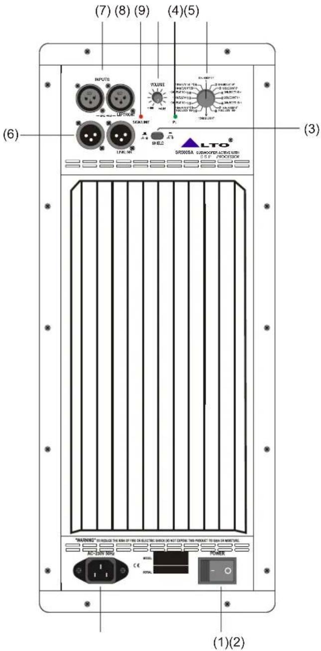
-. Active Subwoofer Speaker for SR500SA
(1) Bi-polar main power switch
(2) Input AC power socket
(3) Ground switch
(4) POWER, blue LED, indicate ON status
(5) SIGN / LIMIT, green/red LED
(6) LINK OUT on XLR connector
(7) LINE / MIC IN on XLR connector
(8) Main VOLUME control
(9) PRESETS control with 16 presets as follows
| Preset NO | Descriptions |
| 1 | 80Hz BOOST 0° |
| 2 | 80Hz BOOST180° |
| 3 | 100Hz BOOST 0° |
| 4 | 100Hz BOOST 180° |
| 5 | 120Hz BOOST 0° |
| 6 | 120Hz BOOST 180° |
| 7 | 140Hz BOOST 0° |
| 8 | 140Hz BOOST 180° |
| 9 | 160Hz BOOST 0° |
| 10 | 160Hz BOOST 180° |
| 11 | 100Hz FLAT 0° |
| 12 | 100Hz FLAT 180° |
| 13 | 120Hz FLAT 0° |
| 14 | 120Hz FLAT 180° |
| 15 | 140Hz FLAT 0° |
| 16 | 140Hz FLAT 180° |
4. WIRE CONNECTIONS
-. For Passive Speaker Cabinets
Please use only the power connectors to make connections with other signal source equipment for the passive speaker cabinets. The power connector has four terminals: 1+, 1-, 2+, 2-.
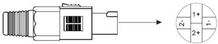
In our cabinets, only 1+/1- are used to connect the Speaker+/Speaker-, and 2+/2- are not used.
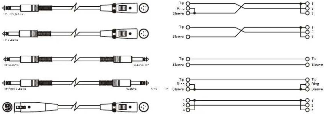
-. For Active Speaker Cabinets
As to these circumstances, audio connections is mostly intended for the signal flow, so, determine the wire configuration according to your real application system and its connecting facility. Normally, you have the following choices:
· Balanced

Unbalanced
- TECHNICAL SPECIFICATIONS
| Descriptions | SR300A | SR500ASR400A | |
| Active System Type | Bi - Amp. With DSP processor | Bi - Amp. With DSP processor | Bi - Amp. With DSP processor |
| LOW - RMS Output Power | 250Watt RMS Class H | 164W @8Ohm, 251W @4Ohm Class H | 232W @8Ohm, 382W @4Ohm Class H |
| HIGH - RMS Output Power | 100Watt RMS Class AB | 164W @8Ohm, 251W @4Ohm Class AB | 232W @8Ohm, 382W @4Ohm Class AB |
| System Peak Power | 600Watt Peak | 800Watt Peak | 1000Watt Peak |
| Max SPL at 1m | 120dB SPL calculated | 122dB SPL calculated | 124dB SPL calculated |
| Frequency Response | 60Hz / 20kHz at -10dB | 55Hz / 20kHz at -10dB | 50Hz / 20kHz at -10dB |
| Impedance Low - High | Low 4ohm - High 8ohm | Low 4ohm - High 8ohm | Low 4ohm - High 8ohm |
| Crossover Frequency | 2250Hz - DSP Processor | 2150Hz - DSP Processor | 2000Hz - DSP Processor |
| Protection Low - High | DSP Lim/Comp. each section | DSP Lim/Comp. each section | DSP Lim/Comp. each section |
| Low Frequency Device | 10" / 266mm - 2" voice coil | 12" / 318mm - 2.5" voice coil | 15" / 385mm - 3" voice coil |
| High Frequency Device | 1.35" Compression-driver | ||
| Horn Coverage H° × V° | 90° H × 60° V | ||
| Input Sensitivity | Mic / Line +4dB / 1.23V | ||
| Input Impedance | 30kohm Balanced / 15kohm Unbalanced | ||
| Connectors | Input with Combo / Link with XLR | ||
| Plywood Cabinet | 18mm Multilayer Plywood | ||
| Hardware Suspension | Five suspension point | ||
| Amplifier Protections | Soft Start - Short Circuit - DC voltage - Thermal Protection | ||
| External Control | Line Volume - Encoder with 16 preset - Clipping LED indicator - Ground Switch | ||
| Power Supply | 230Volt / 115Volt 50 / 60Hz | ||
| Dimensions H W D× | ×565× 346× 355mm | 645× 395× 385mm | |
| Net Weight lbs/kg | 50.7lbs/23.0Kg | 59.77LBS/27.11Kg | |
| Gross Weight lbs/kg | 59.08lbs/26.80Kg | 72.88LBS/33.06Kg | |
| Shipping Volume | 5.21CFT | 6.56CFT | |
| Descriptions | SR500SA |
| Active System Type | Amp. with DSP processor |
| LOW - RMS Output Power | 233W @8Ohm, 378W @4Ohm Class H |
| System Peak Power | 1000Watt Peak |
| Max SPL at 1m | 124dB SPL calculated |
| Frequency Response | 45Hz / 20kHz at -10dB |
| Impedance Low - High | Low 4ohm |
| Crossover Frequency | 16 selectable Crossover |
| Protection Low - High | DSP Limiter / Compressor |
| Low Frequency Device | 15" / 385mm - 3" voice coil |
| Input Sensitivity | Line +4dB / 1.23V |
| Input Impedance | 30kohm Bal. / 15kohm Unbal. |
| Connectors | Input / Output with XLR |
| Plywood Cabinet | 18mm Multilayer Plywood |
| Hardware Suspension | No suspension point |
| Amplifier Protections | Same to SR400A |
| External Control | Same to SR400A |
| Power Supply | 230Volt / 115Volt 50 / 60Hz |
| Dimensions H W D× × | 598 500 600mm(23.54" 19.69"23.62"mm)× × × |
| Net Weight lbs/kg | 93.81LBS/42.55Kg |
| Gross Weight lbs/kg | 104.65LBS/47.47Kg |
| Shipping Volume | 14.29CFT |
| Descriptions | SR500SR300 SR | ||
| Passive System Type | 2 - way vented box | 2 - way vented box | 2 - way vented box |
| Continuos Power | 250Watt AES Standard | 300Watt AES Standard | 350Watt AES Standard |
| Peak Power | 500Watt Peak | 600Watt Peak | 700Watt Peak |
| Max SPL at 1m | 119dB SPL calculated | 121dB SPL calculated | 123dB SPL calculated |
| Frequency Response | 65Hz / 20kHz at -10dB | 60Hz / 20kHz at -10dB | 55Hz / 20kHz at -10dB |
| Impedance | 8ohm | 8ohm or 4ohm | 8ohm or 4ohm |
| Crossover Frequency | 2250 - 12dB/Oct. | 2150 - 12dB/Oct. | 2000 - 12dB/Oct. |
| Protection | Electronic Dynamic Protection | Electronic Dynamic Protection | Electronic Dynamic Protection |
| Low Frequency Device | 10" / 266mm - 2" voice coil | 12" / 318mm - 2.5" voice coil | 15" / 385mm - 3" voice coil |
| High Frequency Device | 1.35" Compression-driver | 1.35" Compression-driver 1.35" | Compression-driver |
| Horn Coverage H° × V° | 90° H × 60° V | ||
| Connectors | 2 × SPK4 @ Power Input / Output | ||
| Plywood Cabinet | 18mm Multilayer Plywood | ||
| Hardware Suspension | Five suspension point | ||
| Dimensions H × W × D | 560× 345× 355mm | 645× 395× 385mm | 680× 455× 440mm |
| Net Weight lbs/kg | 46.76lbs/ 21.21Kg | ||
| Gross Weight lbs/kg | 59.88lbs/ 27.16Kg | ||
| Shipping Volume | 6.56CFT | ||
| Descriptions | SR500S |
| Passive System Type | Direct Radiator / Rear Loaded |
| Continuos Power | 400Watt AES Standard |
| Peak Power | 800Watt Peak |
| Max SPL at 1m | 123dB SPL calculated |
| Frequency Response | 50Hz / 200Hz at -10dB |
| Impedance | 4ohm |
| Crossover Frequency | 125Hz - 12dB/Oct. |
| Low Frequency Device | 15" / 385mm - 3" long voice coil |
| Connectors | 2 × SPK4@ Power Input / Output |
| Plywood Cabinet | 18mm Multilayer Plywood |
| Hardware Suspension | No suspension point |
| Dimensions H × W × D | 598× 500× 600mm(23.54")× (19.69")× (23.62) |
| Net Weight lbs/kg | 78.15LBS/35.45Kg |
| Gross Weight lbs/kg | 89LBS/40.37Kg |
| Shipping Volume | 14.29CFT |
SEIKAKU TECHNICAL GROUP LIMITED
No. 1, Lane 17, Sec. 2, Han Shi West Road, Taichung 40151, Taiwan
http://www.altoproaudio.com Tel: 886-4-22313737
email: alto@altoproaudio.com Fax: 886-4-22346757
All rights reserved to ALTO. All features and content might be changed without prior notice. Any photocopy, translation, or reproduction of part of this manual without written permission is forbidden. Copyright © 2006 SEIKAKU GROUP
- ▲"Electric discharge"
- ▲"Exclamatory point"
- Read Instructions
- Water & Moisture
- Heat
- Liquid Entry
- Service Assistance
- Package
- Hearing
- Installations
- TABLE OF CONTENT
- QUICK START - PASSIVE SPEAKER CABINET
- -. For Passive Full-range Speakers
- QUICK START
- SR Passive Full-range Speakers
- -. For Passive Subwoofer & Satellite Speakers
- SR Passive Subwoofer & Satellite Speakers
- QUICK START - ACTIVE SPEAKER CABINET
- -. For Active Full-range Speakers
- -. For Active Subwoofer & Satellite Speakers
- CONNECTION PLATE
- -. Active Full-range Speaker for SR300A / SR400A / SR500A
- -. Active Subwoofer Speaker for SR500SA
- WIRE CONNECTIONS
- -. For Passive Speaker Cabinets
- -. For Active Speaker Cabinets
Brand : ALTO
Model : SR400A
Category : Loudspeaker