enVision - Uncategorized SurgeX - Free user manual and instructions
Find the device manual for free enVision SurgeX in PDF.


User questions about enVision SurgeX
0 question about this device. Answer the ones you know or ask your own.
Ask a new question about this device
Download the instructions for your Uncategorized in PDF format for free! Find your manual enVision - SurgeX and take your electronic device back in hand. On this page are published all the documents necessary for the use of your device. enVision by SurgeX.
USER MANUAL enVision SurgeX
bar
| Voltage Range (V) | Current (A) | |---|---| | 119.21 | 0 | | 0.004 | 0 | | 0.0 | 5 | | 0.324 | 400 | | 59.99 | 1 | | 0.828 | 56 | | 1.410 | 0.2 | | 59.99 Hz | 57 | | 0.828 PF | 0.4 | | 1.410 CF | 1.4 | The chart displays 'enVision' as a connected device with color-coded bars indicating 'SG', 'OVoff', and 'OVrec' categories. The bottom panel shows a 'energy intelligence' icon with an 'ESPE SURGE X' logo and '140Hz'. The right-side scale indicates percentage from 0% to 100%. The device is labeled 'enVision'.User Manual
120 and 208-240 Volt Models
AMETEK®
ELECTRONIC SYSTEMS PROTECTION
ADVANCED SERIES MODE®
AXESS®
COUVS®
DEFENDER SERIES®
DIGITAL QC®
ECOMMANDCENTER®
ELIMINATOR SERIES™
EMPOWER®
ENERGY INTELLIGENCE®
ENVISION®
ESP®
FLATPAK™
ICE®
IMPEDANCE TOLERANT™
INRUSH CURRENT ELIMINATION®
MULTIPAK®
MULTI-STAGE®
NEXT GEN®
PCS™
POWERFRAME®
REMOTE PORTAL®
SERIES MODE®
SURGE ELIMINATION®
SURGEX®
SURGEXICE®
This product may be covered by one or more claims of the following patents or published patent application:
U.S. Patent Nos.: RE39,466; 2,461,332; 4,870,528; 4,870,534; 5,136,455; 6,040,969; 6,728,089; 6,744,613; 6,947,266;
7,068,487; 7,184,252; 7,511,934; 7,541,696; and 7,551,412; 8,482,885; 8,520,349; 8,547,672; 8,614,866; 9,166,396;
9,225,534; 9,310,870; 10,014,680; 10,090,622; 10,114,395
U.S. Patent Application Publication Nos.: 2012/0221161; 2013/0073232
Canadian Patent Nos.: 1,332,439; 1,333,191; 2,461,332 and 2,511,695
I. PRODUCT OVERVIEW....4
- MODELS....4
- KEY FEATURES....4
- TECHNICAL SUPPORT 4
II. INSTALLATION INSTRUCTIONS....5
- FILTER INSTALLATION....5
a. TURN OFF EQUIPMENT 5
b. CONNECT MODEM/FAX LINE 5
c. CONNECT 10/100/1000 ETHERNET NETWORK LINE 5
d. CONNECT EQUIPMENT 6
e. CONNECT FILTER TO OUTLET....7
III. HARDWARE....8
-
FILTER....8
a. LCD EVENT MONITOR 8
I. NORMAL OPERATION....8
II. WIRING FAULT 10
III. ABNORMAL VOLTAGE....10
b. CLEARING MEMORY 11
I. BUTTONS....11
II. DIAGNOSTIC SOFTWARE 11 -
DATA INTERFACE CABLE 12
a. OVERVIEW 12
b. INSTRUCTIONS FOR DATA RETRIEVAL 12
c. INSTRUCTIONS FOR EV-230XX DATA RETRIVIAL....12
IV. SOFTWARE INSTALLATION .... 13
- COMPUTER REQUIREMENTS ...... 13
- HARDWARE REQUIREMENTS.... 13
- DOWNLOAD AND INSTALL SOFTWARE 13
- ANDROID APP DOWNLOAD 13
- INSTALL DATA INTERFACE CABLE 14
V. USING THE SOFTWARE....14
- PHYSICAL CONNECTIONS 14
- START THE SOFTWARE....14
- CONFIGURE THE DATA INTERFACE CABLE AND COM PORT....15
- SOFTWARE MODES 17
a. MULTIMETER MODE....18
b. SCOPE MODE....19
c. CHART MODE....21
d. OUTLET CONTROL MODE 22
e. HISTORICAL DATA MODE 23
f. SETTINGS MODE 28
g. COM PORT SETUP MODE....30
The enVision PCS is a state-of-the-art, microprocessor-controlled, power filter engineered with real-time data acquisition and storage.
- Models: This manual applies to the following enVision models:
| Model Number | Voltage (AC RMS) | Current (AC Amps) | Outlet |
| EV-12010 BR | 120 | 10 | |
| EV-12015 | 120 | 15 | |
| EV-12016 BR | 120 | 16 | |
| EV-12020 | 120 | 20 | |
| EV-20815 | 208-240 | 15 | |
| EV-20816 BR | 208-240 | 16 | |
| EV-20820 | 208-240 | 20 | |
| EV-20830-630 | 208-240 | 30 | |
| EV-20830-L630 EV-20830-L630-GNS | 208-240 | 30 | |
| EV-23010 | 240 | 10 | |
| EV-23016 | 240 | 16 | |
| EV-23016-F | 240 | 16 | |
| EV-23030-GNS | 240 | 30 |
2. Key Features:
• Normal and Common Mode EMI Noise Filter
• 3-Stage Normal and Common Mode AC Surge Suppressor
• CAT6 Network Line Surge Suppressor
• Modem/Fax Line Surge Suppressor (Note: Not available for EV-230xx)
- Inrush Current Elimination with Zero-Voltage Turn-On and Zero- Current Turn-Off (ICE Zero)
- Wiring Fault Detection
- Catastrophic Over/Under Voltage Shutdown (COUVS ^ ) with selectable thresholds
• Under-Voltage Event Recorder (up to 65535 events)
• Over-Voltage Event Recorder (up to 65535 events)
• Power Outage Event Recorder (up to 65535 events)
- Surge Event Recorder (up to 65535 events)
- Records surges in all three modes: Line-Neutral, Line-Ground, Neutral-Ground (120V)
Records surges in all three modes: Line1-Line 2, Line1-Ground, Line2-Ground (208-240V)
• Event Timestamp Recorder (up to 512 events)
- Records actual date and time of events
- Internal logging of measured parameters
○ Average power, maximum power, average voltage, maximum voltage, minimum voltage, maximum current of 30 minute intervals for up to 138 days
○ Line voltage, current, power, NG voltage, frequency, power factor, crest factor, energy sampled every 10 seconds for up to 2.25 days
• Additional features available when connected to a PC (detailed in Diagnostic Software User Manual)
3. Technical Support:
• To download software and access further product information, visit www.ametekesp.com
• For enVision PCS technical support, please contact ESP at 1-800-645-9721
- To download software and access further product information, visit www.ametekesp.com - For enVision PCS technical support, please contact ESP at 1-800-645-9721
II. INSTALLATION INSTRUCTIONS
1. Filter Installation:
a. Turn off the machine you are connecting to the Filter, and unplug the machine's power cord from wall outlet.
natural_image
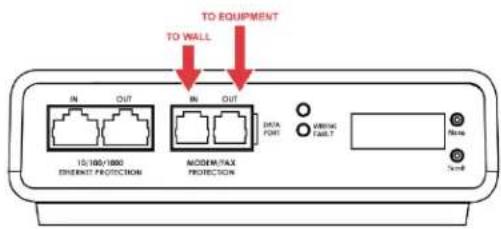
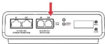
Black electronic device with attached cable and power plug (no visible text or symbols)b. Connect Modem/Fax line: Connect a phone cord from the wall jack to the "Modem/Fax" modular jack labeled "IN", and then connect a second phone cord from the "Modem/Fax" modular jack labeled "OUT" to the machine/equipment to be protected. The EV-23010 and EV-23016 models do not support a Modem Fax telco port.
Please Note: The Filter only provides connectivity and protection for a single phone line.
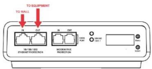
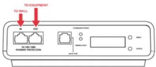
c. Connect "10/100/1000 ETHERNET" network line: Connect a CAT6 network cable from the wall jack to the "10/100/1000 ETHERNET" modular jack labeled "IN", and connect a second CAT6 network cable from the "10/100/1000 ETHERNET" modular jack labeled "OUT" to the equipment to be protected.
One CAT6 network cable is included with the Filter.
EV-12015/20
EV-20815/20
EV-23010
EV-23016
d. Connect Equipment
i. Make sure that the total amperage of all equipment plugged into the Filter does not exceed the maximum branch circuit rating.
ii. Connect the AC power cords of the equipment to be protected into the short output power cord of the Filter or two convenience receptacles next to the short output power cord.
Please Note: Exceeding the branch circuit rating will cause the branch circuit breaker to trip.
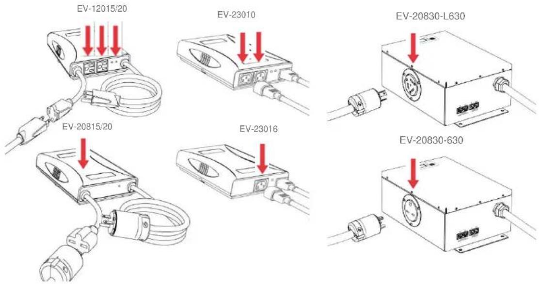
e. Connect Filter to Outlet: Plug the Filter input power cord into a properly grounded and compatible branch circuit outlet. The plug is used as the disconnect device.
Please Note: Do not plug the Filter into a re-locatable power tap.
i. If the branch circuit outlet is correctly wired and the magnitude of the line voltage is acceptable (between 105 and 140 V_RMS for 120V products, or between 190 and 260 V_RMS for 208-240V products), power will be connected to the outlets of the Filter and the Green "System On" LED will illuminate. Your equipment is now protected and installed correctly. You may now turn all connected equipment back on.
ii. If the branch circuit outlet is incorrectly wired, the Red 'Wiring Fault' LED will illuminate and the LCD will display specific wiring fault information. If this occurs, contact a licensed electrician to correct the outlet wiring. Refer to Section III: Hardware/EnVision PCS Filter, for LCD EVENT MONITOR display details.
iii. If neither "System On", nor the "Wiring Fault" LED illuminates, there is either no voltage at the receptacle or the magnitude of the line voltage is not acceptable (less than 105VRMS or above 140VRMS for 120V products, or less than 190VRMS or above 260VRMS for 208-240V products). If the magnitude of the line voltage is not acceptable, specific information will be displayed on the LCD. If this occurs, contact a licensed electrician to trouble-shoot the abnormal voltage condition. Refer to Section III: Hardware/EnVision PCS Filter, for LCD EVENT MONITOR display details.
- You may also need to verify that the Filter is operating properly. To test, plug the Filter into a known properly functioning outlet. If the "System On" LED still does not illuminate in the functioning outlet, contact ESP at 1-800-645-9721.
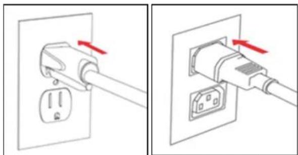
natural_image
Two diagrams showing a plug inserted into a socket, with red arrows indicating direction of insertion (no text or symbols present)EV-23010
- Protection against short-circuits and earth faults shall be provided as part of the building installation.
- The socket-outlet shall be installed near the equipment and shall be easily accessible.
- A dedicated Earth Ground (PE) wire is required in addition to line voltage.
III. HARDWARE
1. Filter
a. LCD Event Monitor
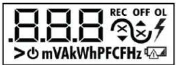
The LCD EVENT MONITOR displays useful information related to data collection, device status, and troubleshooting.
i. Normal Operation
- When the EnVision PCS Filter is plugged into a branch circuit outlet with correct wiring and acceptable line voltage, the LCD Event Monitor will display the following information:
| Menu | Item | Example Display |
| Electrical Parameters (EP) | Line Voltage | 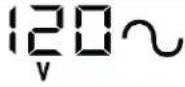 |
| Neutral-Ground Voltage | 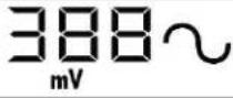 | |
| Load Current Draw | 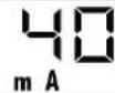 | |
| Load Power Draw | 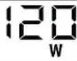 | |
| Load Energy Usage |  | |
| Crest Factor | 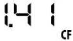 | |
| Power Factor | 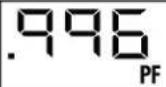 | |
| Line Frequency | 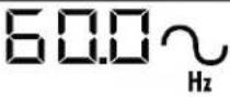 |
| Power Disturbances (Pd) | Power Outages |  | |
| Under Voltages (Off) | 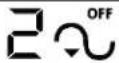 | ||
| Under Voltages (Record) | 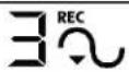 | ||
| Over Voltages (Record) | 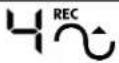 | ||
| Over Voltages (Off) | 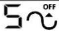 | ||
| Surges | 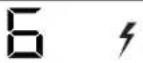 | ||
| Overload | 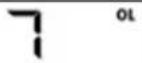 | ||
| Last Recorded Event | 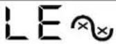 | ||
| Outlet State (OS) | On / Off |  | |
| User Control (UC)Press and hold Menu and Scroll buttons to perform control action. | Turn Outlets On / Off | 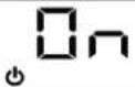 | |
| Memory All Clear (ALC) | 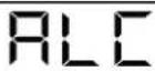 | ||
| Disturbance History Clear (dhC) | 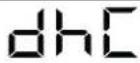 | ||
| Power Usage Clear (PUC) | 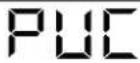 | ||
| Disturbance Count Clear (dcC) | 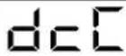 | ||
| Energy Display Clear (EdC) | 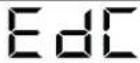 | ||
| Chart Data Start (cdS) | 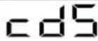 |
ii. Wiring Fault
When connected to an incorrectly wired branch circuit outlet, in addition to the illumination of the Red LED, the LCD Event Monitor will display the following information:
| Wiring Fault Condition | Display | Example Display |
| Line (Hot) / Neutral Reversed(120V products only) | rP (Reverse Polarity) |  |
| Missing Ground | gnd (no Ground) | 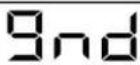 |
iii. Abnormal Voltage
When the magnitude of the branch circuit outlet voltage is not acceptable*, the Filter will disconnect power to its outlets and display the following information on the LCD Event Monitor (*above the over-voltage shutdown threshold or below the under-voltage shutdown threshold; refer to Section IV: Diagnostic Software for more information):
| Voltage Condition | Display | Example Display |
| Over-Voltage | OFF + ▲ + Voltage | 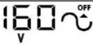 |
| Under-Voltage | OFF + ▼ + Voltage | 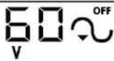 |
b. Clearing Memory:
The memory contents of the Filter can be cleared at any time by following one of these two methods:
i. Buttons:
Follow these steps to clear the device memory:
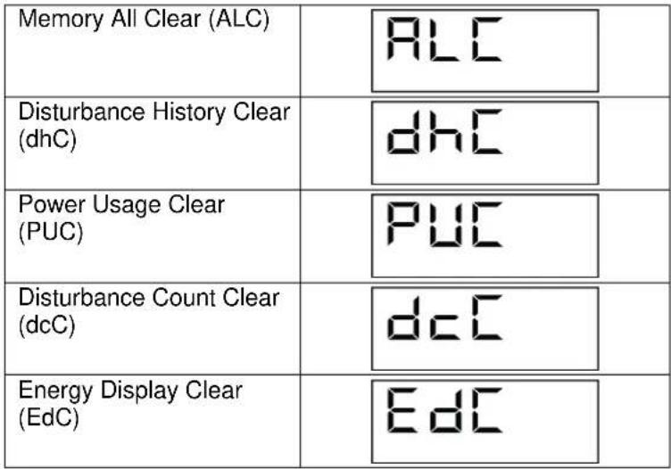
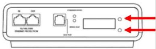
- Press the Menu button until "UC" (User Control) is displayed.
- Next, press the Scroll Button to select which memory record to erase:
 |
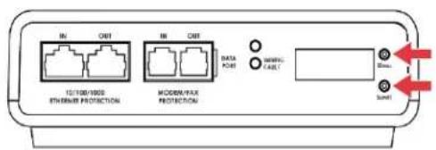
- Finally, press and hold both Menu and Scroll buttons at the same time until "Clr" is displayed, and then release.
EV-23010
ii. Diagnostic Software:
The device memory may alternately be cleared from within the Diagnostic Software. See "Using the Software" in this manual for details.
2. Data Interface Cable
a. Overview
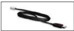
i. The Data Interface Cable consists of a USB connection on one end, and a RJ-11 connection on the opposite end.
ii. The USB connection plugs into an available USB port on your PC. The RJ-11 connection plugs into the RJ-11 "OUT" Jack (labeled "Data Port") on the enVision Filter, which is the jack closest to the LCD and buttons.
b. Instructions for Data Retrieval
i. Disconnect any protected Modem/Fax lines connected to the "IN" and "Out" RJ-11 modular jacks on the Filter. Ethernet connections (RJ-45) may remain in place.
ii. Connect the Data Interface Cable into the USB port on your PC.
iii. Connect the Data Interface Cable into the RJ-11 "OUT" Jack (labeled "Data Port") on the Filter. It is the jack closest to the LCD and buttons.
iv. Open the Diagnostic Software.
v. When you are finished, be sure to re-connect the Modem/Fax lines to the "IN" and "Out" RJ-11 modular jacks on the Filter.
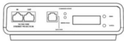
c. Instructions for EV-23010/EV-23016 Data Retrieval
i. Ethernet connections (RJ-45) may remain in place.
ii. Connect the Data Interface Cable into the USB port on your PC.
iii. Connect the Data Interface Cable into the RJ-11 Jack (labeled "Data Port"). It is the jack closest to the LCD and buttons.
iv. Open the Diagnostic Software.
v. When you are finished, remove the Data Interface Cable from the RJ-11 Jack.
IV. SOFTWARE INSTALLATION
1. Computer Requirements
a. Minimum 133MHz Pentium processor (or equivalent), minimum 64MB of RAM, minimum 10MB free hard drive space, VGA or higher resolution monitor, keyboard, mouse, CD or DVD drive, minimum screen resolution of 1024x768, Microsoft Windows XP/Vista/7/8.
2. Hardware Requirements
a. For use with enVision enabled products and Data Interface Cable (XG-PCS-1C-1)
3. Download and Install Software
a. Download the Software Installer from the download tab at: www.amatekesp.com/esp/envision/envision-120-208v
b. Unzip and run the installation utility.
c. Follow the on-screen instructions to complete installation of the software.
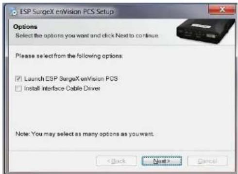
4. Android App Download
a. The App can be used to view the enVision's analytical software from an Android device
b. Visit the Google Play store at https://play.google.com/store and search for ESP enVison to download the App. It can also be downloaded directly at https://play.google.com/store/apps/details?id=com.espsurgex.envison.
c. Requires USB OTG (On The Go) adapter, Android device with USB OTG support, and ESP USB interface cable (XG-PCS-IC-1)
5. Install Data Interface Cable
a. Automatic Installation (Requires Internet connection)
i. Plug the USB side of the Data Interface Cable into an available USB port.
ii. Windows will automatically detect and install appropriate device driver files for the Data Interface Cable.
- If a "Found New Hardware" pop-up box appears, follow the on-screen instructions and allow Windows to search online for driver files.
- The installation could take several minutes to search for and download appropriate driver files. Once the files are found, follow the on-screen instructions to install.
- Note: The driver installation process will first install USB Serial Converter driver files, and then will install USB Serial Port drivers separately.
b. Manual Installation
In the event that the automatic driver installation process was not successful, or if no internet connection is available, the Data Interface Cable driver files may be installed manually.
- Select "Install Drivers" during the Software Installation process.
- Or run "Interface Setup" from: Start/All Programs/ESP SurgeX/Diagnostic Tool
c. Once the Data Interface Cable has been successfully installed, it will appear in Device Manager as "USB Serial Port (COMx)" under "Ports (COM & LPT)".
V. USING THE SOFTWARE
1. Physical Connections
a. Plug the USB side of the Data Interface Cable into an available USB port.
b. Plug the RJ-11 side of the Data Interface Cable into the RJ-11 "OUT" jack labeled "Data Port" on the enVision enabled unit, which is the jack closest to the LCD.
c. Note: The enVision PCS must be powered by AC Mains for communications with the software to operate.
2. Start the Software
a. Double-click the desktop shortcut labeled "ESP SurgeX Diagnostic Tool", or use the "ESP SurgeX Diagnostic Tool" Start Menu shortcut located at:
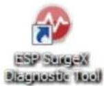
Start/All Programs/ESP SurgeX/Diagnostic Tool
3. Configure the Data Interface Cable and COM Port
a. Click the COM Port Setup button labeled COM.
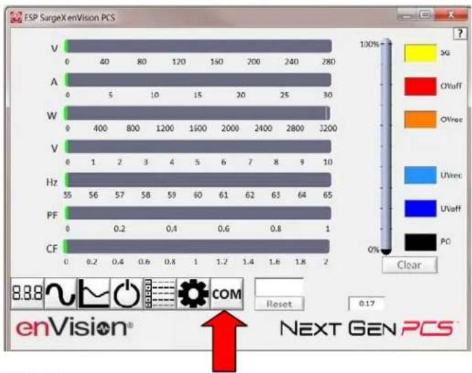
bar
ESP SurgeX enVision PCS | Component | Value | |---|---| | V | 0 | | A | 0 | | W | 0 | | V | 0 | | Hz | 55 | | PF | 0 | | CF | 0.2 | 1200 1600 2000 2400 2800 1200 1 2 3 4 5 6 7 8 9 10 57 58 59 60 61 62 63 64 65 0.4 0.6 0.8 1 COM Reset 0.17 Clear ENVision® NEXT GEN PCSb. Click Configure.
i. The auto configuration process will automatically set the correct device parameters of the Data Interface Cable to operate properly with the software and enVision.
• Note: This process only needs to be done once for each new Data Interface Cable installed on the PC.
- Note: This process edits Windows registry values, and so may be blocked by MS Windows User Account Control (UAC) in Windows Vista/7/8/10. It may be necessary to exit the software and restart it with administrative rights by right-clicking the software shortcut and choosing "Run As Administrator". It may also be necessary to run the compatibility wizard by right-clicking the shortcut, selecting "Troubleshoot Compatibility", and following the prompts.
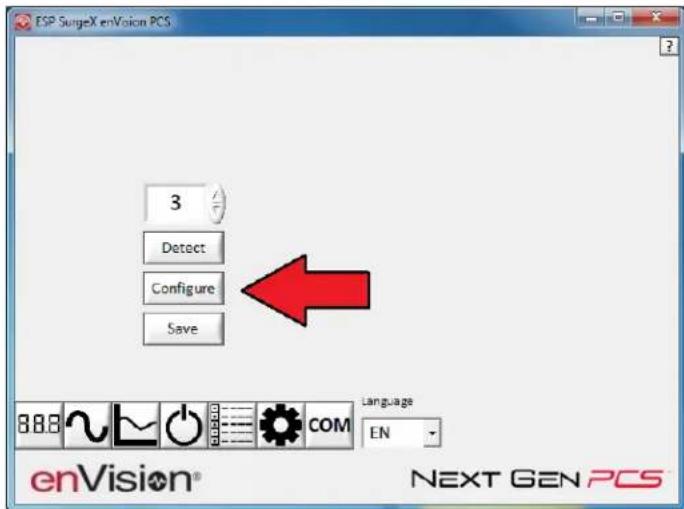
ii. The COM port may also be manually configured using the Device Manager:
- Open Device Manager
a. Click on Start button
b. Type the following command in the Search box: devmgmt.msc
c. Press Enter
-
In the Device Manager, expand "Ports (COM & LPT)"
-
Right-click on the entry labeled "USB Serial Port (COMx)" and click "Properties"
-
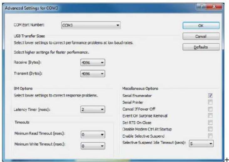
In the USB Serial Port Properties pop-up box, click the "Port Settings" tab, and then click the "Advanced" button.
-
In "USB Transfer Sizes", change both the "Receive" and "Transmit" values to 4096.
-
In "BM Options", change the "Latency Timer" value to 2.
-
Leave all other settings at default.
c. Click Detect.
i. The auto detect process will automatically detect the COM Port number assigned to the Data Interface Cable.
ii. If the auto detection process is successful, click Save. The software is now properly configured and ready for use.
iii. If the auto detection process is not successful, verify that the Data Interface Cable device drivers are properly installed, and that the physical connections between the enVision and the PC have been made correctly.
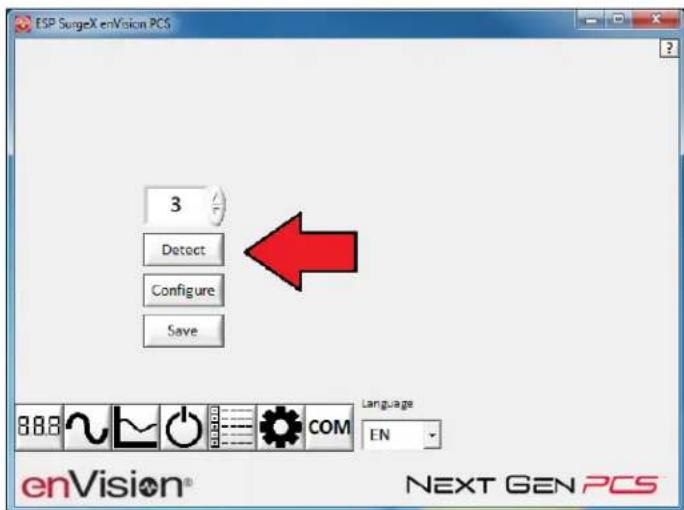
d. The language may also be selected in this mode.
4. Software Modes
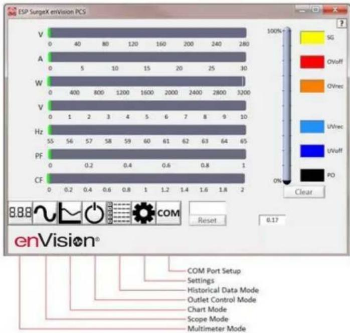
The enVision Software is organized into several operational modes. The modes are activated by clicking the corresponding button at the bottom of the software interface.
Press the Help Button ("?") in the upper right for additional information on the features available in the current mode. Hovering the mouse cursor over items will also display additional information.
Scope Mode, Chart Mode, Historical Data Mode, and Settings Mode include a Save function. Press the Save button to save data to a CSV file. Time Stamped data may also be saved as a report in PDF format.
Chart Mode and Historical data may be analyzed by an automatic Expert Analysis tool. Press the Expert button to perform an expert analysis of recorded time-stamped event data, historical data, or chart measurements and generate a PDF report of potential conclusions and recommendations.

bar
ESP SurgeX enVision PCS | Component | Frequency (Hz) | Mode Color | Frequency (V) | | :--- | :--- | :--- | :--- | | V | 55 | SG | 0 | | A | 55 | Ovoff | 0 | | W | 55 | Ovrec | 0 | | V | 64 | UVrec | 0 | | Hz | 64 | UVvuff | 0 | | PF | 64 | PO | 0 | | CF | 1 | COM | 0 | | 8.88 | 0.17 | Reset | 0.2 | | COM Port Setup | 0.17 | Settings | 0.4 | | Historical Data Mode | 0.17 | Outlet Control Mode | 0.6 | | Chart Mode | 0.17 | Scope Mode | 0.8 | | Multimeter Mode | 0.17 | — | 1 | The chart displays a horizontal bar chart with color-coded modes and their corresponding frequencies. The 'Clear' label indicates the status of the data series.a. Multimeter Mode
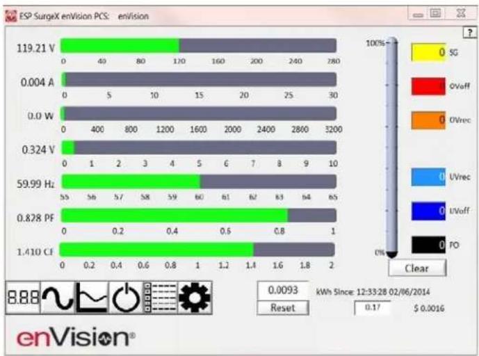
i. The Multimeter Mode provides information traditionally acquired from one or more handheld digital multimeters, as well as an overview of the recorded power quality events and energy consumption of connected equipment. ±2% Measurement Accuracy.
bar
| Voltage Range | 119.21 V | 0 | 40 | 80 | 120 | 160 | 200 | 240 | 280 | |---|---|---|---|---|---|---|---|---|---| | 0.004 A | 0 | 5 | 10 | 15 | 20 | 25 | 30 | 30 | 30 | | 0.0 W | 0 | 400 | 800 | 1200 | 1600 | 2000 | 2400 | 2800 | 3200 | | 0.324 V | 0 | 1 | 2 | 3 | 4 | 5 | 6 | 7 | 8 | | 59.99 Hz | 55 | 56 | 57 | 58 | 59 | 60 | 61 | 62 | 63 | | 0.828 PF | 0 | 0.2 | 0.4 | 0.6 | 0.8 | 1.0 | 1.2 | 1.4 | 1.6 | | 1.410 CF | 0 | 0.2 | 0.4 | 0.6 | 0.8 | 1.0 | 1.2 | 1.4 | 1.6 | The chart displays a stacked bar format representing voltage ranges for each component, with color-coded segments indicating the type of signal: SG (yellow), OVeff (red), OVrec (orange), UVrec (blue), UVoff (dark blue), PO (black). The bottom panel shows a 'OK' button at the bottom right indicates 'kWh Since: 12:33:28 02/06/2014'. The 'Reset' button is labeled '0.17 $ 0.0016'. The 'Clear' button is also shown.ii. Real-time display of 8 electrical parameters
• Line Voltage: AC RMS Volts Line-Neutral (Line1-Line2)
- Load Current Draw: AC RMS Amps
- Load Power Draw: Watts
- Neutral-Ground Voltage: AC RMS Volts Neutral-Ground (Line2-Ground)
• Line Frequency: Hertz
- Load Power Factor
• Line Voltage Crest Factor
• Energy Usage (kWh) of connected equipment since date and time of last manual usage reset
iii. Number of recorded power quality events
- Surge Events: SG
• Overvoltage Events with turn off of connected equipment: OVoff
• Overvoltage Events with no turn off of connected equipment: OVrec - Undervoltage Events with no turn off of connected equipment: UVrec
• Undervoltage Events with turn off of connected equipment: UVoff
• Power Outage Events: PO
b. Scope Mode
i. The Scope Mode enables a real-time voltage, current, and power oscilloscope which incorporates many functions available in standalone oscilloscopes. 4kHz Oscilloscope Bandwidth.
ii. Ch1-Ch3 buttons toggle waveform displays.
- Ch1 button toggles line voltage trace.
- Ch2 button toggles load current trace.
• Ch3 button toggles load power trace.
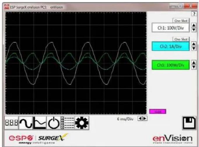
iii. Up ▲ and Down ▼ Arrow buttons adjust the vertical axis scaling of each channel.
iv. Left ◀ and Right ▶ Arrow buttons adjust the horizontal (time) axis scaling.
v. While in normal operation, pressing the Wait button will freeze the currently displayed waveform.
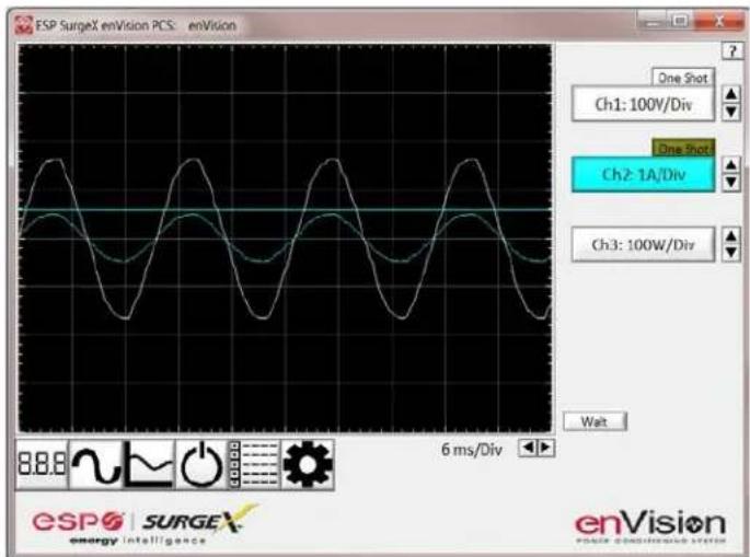
vi. One Shot Trigger Function
- The scope may be set to acquire and hold a waveform display, triggered by either Voltage or Current level.
- Press the One Shot button above the desired channel. A trigger level cursor will appear on the display.
- Next, Drag the trigger level cursor to the desired amplitude and press the Wait button
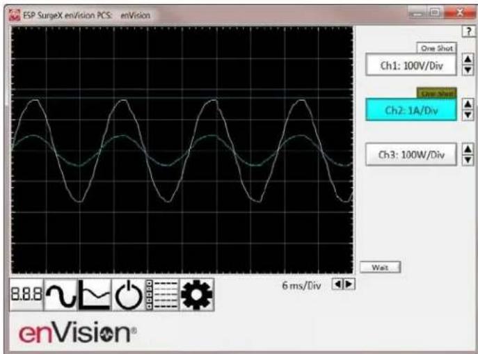
- If the Voltage of Current exceeds the trigger level, the scope will hold the display
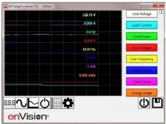
c. Chart Mode
i. The Chart Mode enables a chart style data logging function of 8 electrical parameters. Data point measurements are acquired once per second. The measured parameters may be enabled or disabled by pressing the corresponding button.
line
| Parameter | Value | | ----------------- | --------- | | Line Voltage | 118.73 V | | Load Current | 0.004 A | | Load Power | 0.0 W | | N-G Voltage | 0.519 V | | Line Frequency | 59.97 Hz | | Power Factor | 1.40B | | Crest Factor | 0.009 kWh | | Energy Usage | 0.009 kWh |ii. Chart display of 8 electrical parameters:
• Line Voltage: AC RMS Volts Line-Neutral (Line1-Line2)
- Load Current Draw: AC RMS Amps
- Load Power Draw: Watts
- Neutral-Ground Voltage: AC RMS Volts Neutral-Ground (Line2-Ground)
• Line Frequency: Hertz
- Load Power Factor
• Line Voltage Crest Factor
• Energy Usage (kWh) of connected equipment since date and time of last manual usage reset
d. Outlet Control Mode
i. The Outlet Control Mode enables control of the AC outlets and provides information about wiring faults and abnormal line voltage.
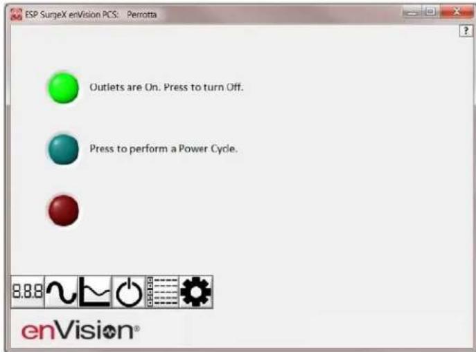
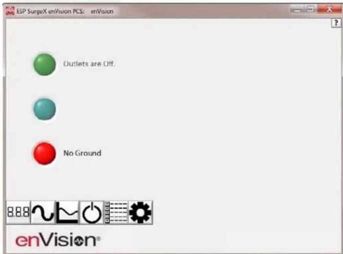
ii. Use the green On/Off button to manually turn the AC outlets on and off.
- Pressing the blue Power Cycle button will result in the execution of a power cycle. When commanded, the outlets will turn off, and then back on, after a 90 second delay. The Power Cycle indicator will be illuminated while a power cycle is active.
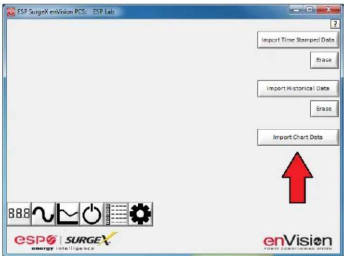
e. Historical Data Mode
The Historical Data Mode allows for the retrieval and display of the power quality event and electrical parameter data stored in the enVision internal memory.
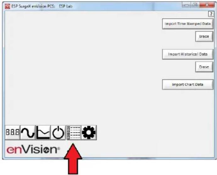
i. Time Stamped Power Quality Event Data
- enVision is able to store and timestamp the 512 most recent power quality events in its internal memory. Press the Import Time Stamped Data button to download the event data.
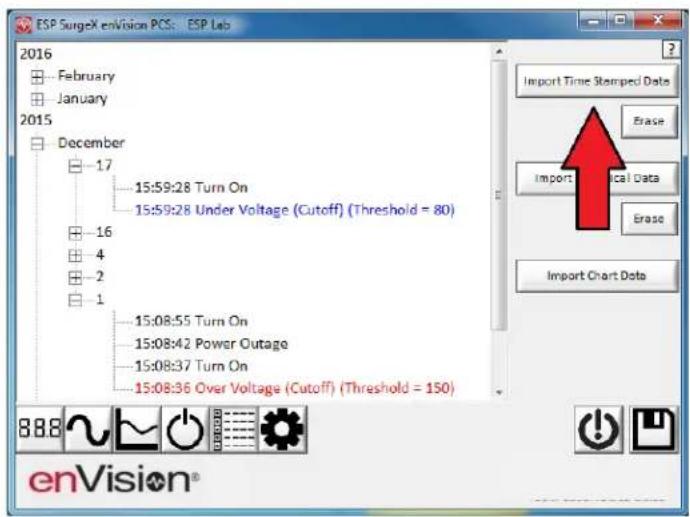
Twelve types of events are logged:
■ Overload: Load current draw has exceeded 25A
- Surge: enVision has been exposed to a transient voltage in one of the 3 possible modes (between Live and Neutral, between Live and Ground, between Neutral and Ground) with a peak amplitude of 500V^* or higher and a frequency of 20kHz or higher. *500V surge voltage amplitude applies to IEEE C62.41 Category B Impulse; surge voltage amplitudes necessary for detection of other surge types may vary.
- Over Voltage (Cutoff): Line voltage exceeded the over voltage shutdown threshold, and connected equipment was turned off.
- Over Voltage (Record): Line voltage exceeded the over voltage record threshold, and connected equipment was not turned off.
■ Under Voltage (Record): Line voltage dropped below the under voltage record threshold, and connected equipment was not turned off.
■ Under Voltage (Cutoff): Line voltage dropped below the under voltage shutdown threshold, and connected equipment was turned off.
■ Power Outage: Loss of AC power.
■ Turn On: The enVision outlets were turned on.
■ Turn Off (Cycle): A power cycle was initiated by a received command.
■ Turn Off (Software): Outlets were turned off by a received command.
■ Turn Off (Button): Outlets were turned off by the pushbuttons.
■ Turn Off (Loss of Ground): Outlets were turned off due to the loss of the safety ground conductor at the wall receptacle.
ii. Historical Electrical Parameter Data
Every 30 minutes, enVision stores a snapshot of 6 electrical parameters measured over the prior 30 minute interval. The internal memory can store 138 days of data. Press the Import Historical Data button to download the data.
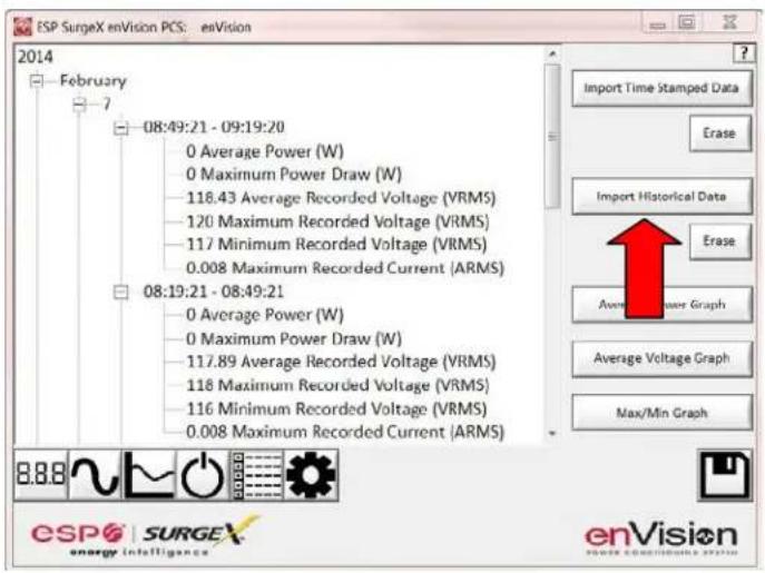
Six electrical parameters are logged:
- Average Power (Watts): The average real power draw of connected equipment during the 30 minute recording interval.
■ Maximum Power Draw (Watts): The highest real power draw measured during the 30 minute recording interval. - Average Recorded Voltage ( V_RMS ): The average line voltage during the 30 minute recording interval.
■ Maximum Recorded Voltage ( V_RMS ): The highest line voltage measured during the 30 minute recording interval. - Minimum Recorded Voltage ( V_RMS ): The lowest line voltage measured during the 30 minute recording interval.
■ Maximum Recorded Current ( A_RMS ): The highest current draw measured during the 30 minute recording interval.
After the historical electrical parameter data has been downloaded, it may be saved to a file or graphically displayed by pressing one of the 3 Graph buttons.
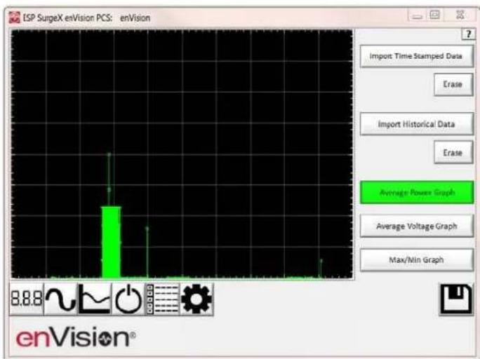
1. Average Power Graph
Pressing the Average Power Graph button will display a bar graph of the average real power draw of connected equipment during each 30 minute recording interval.
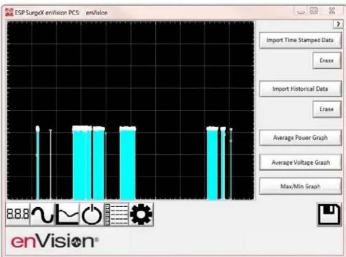
2. Average Voltage Graph
Pressing the Average Voltage Graph button will display a bar graph of the average line voltage during each 30 minute recording interval.
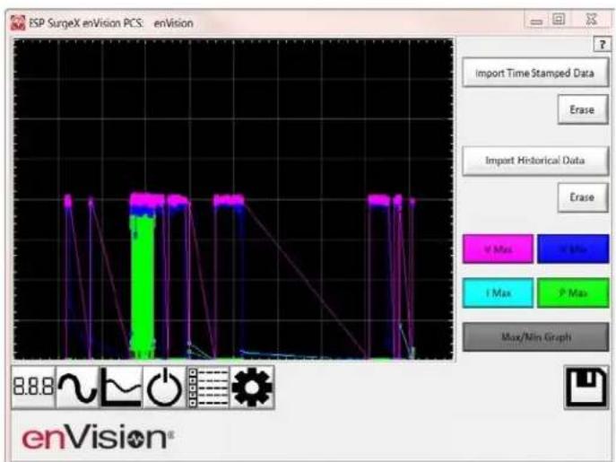
3. Max/Min Graph
Pressing the Max/Min Graph button will display line graphs of maximum voltage, minimum voltage, maximum current draw, and maximum power draw during each 30 minute recording interval.
Pressing the V Max, V Min, I Max, or P Max buttons will enable or disable the display of the corresponding parameter.
iii. Internal Chart Data
When enabled, enVision will log the line voltage, load current, load power, Neutral-Ground voltage, line frequency, power factor, crest factor, and energy usage once every 10 seconds for up to 2.25 days. Press the Import Chart Data button to download the data. Once downloaded, the data may be viewed and interacted with in the same manner described in the Chart Mode section above.
iv. Import Data
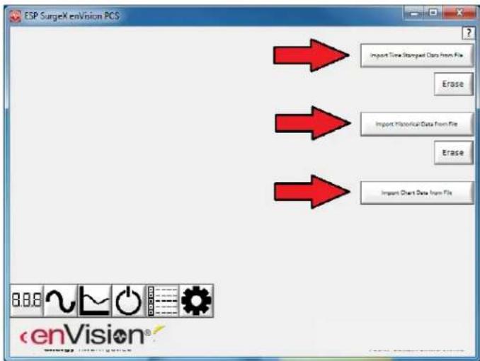
Previously saved data files may be imported by entering the Historical Data Mode while no enVision product is connected. This may be achieved by removing the data interface cable or by selecting and saving an invalid COM Port number.
Press the button that corresponds to the type of data file to import and browse to the location of the file.
f. Settings Mode
The Settings mode enables the specification of the user-configurable parameters of enVision. When this mode is entered, it displays the parameters currently in use. Firmware versions prior to 1.KD1 may not support all settings.
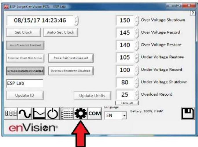
i. Auto Set Clock: Automatically sets the internal clock to the current date and time.
ii. Set Clock: Sets the internal clock to a date and time manually specified in the date/time field.
iii. Auto Transmit: Enables/Disables the automatic transmission of status information every 30 minutes.
iv. Internal Chart: Start or re-start the internal logging of electrical parameters.
v. Ground Detection: Enables/Disables the ability of enVision to detect and respond to an open Ground connection. Disabling may be necessary in order to power enVision from a UPS output, but in general it is highly recommended to leave this feature enabled.
vi. Overload Shutdown: Enables/Disables the ability of enVision to turn off connected equipment when a current overload condition is detected. After this occurs, the outlets will not be automatically turned back on.
vii. Power Fail Hold: When enabled, enVision will keep its outlets off following a power outage or shutdown event. The outlets must be manually turned back on using software or the MENU and SCROLL buttons.
viii. Update ID: Sets the product identifier specified in the text box. 10
character limit.
ix. Update Limits: Sets the 6 voltage thresholds specified by the voltage threshold selection fields. Press Default to select factory default limits.
x. Language: Select the software's display language.
xi. Save: Save the current settings for reference.
| Limit | When Activated | Action | Factory Default | |
| 120V | 208/240V | |||
| Over Voltage Shutdown | V > OV_Shutdown | Outlets turned Off and event recorded | 150 | 280 |
| Over Voltage Record | OV_Shutdown > V > OV_Record | Outlets stay On and event recorded | 145 | 270 |
| Over Voltage Restore | V < OV_Restore After OV_Shutdown | Outlets turned On and event recorded | 140 | 260 |
| Under Voltage Restore | V > UV_Restore After UV_Shutdown | Outlets turned On and event recorded | 105 | 190 |
| Under Voltage Record | UV_Shutdown < V < UV_Record | Outlets stay On and event recorded | 100 | 180 |
| Under Voltage Shutdown | V < UV_Shutdown | Outlets turned Off and event recorded | 80 | 160 |
g. COM Port Setup Mode
i. The COM Port Setup mode is used to configure new Data Interface Cables for use.
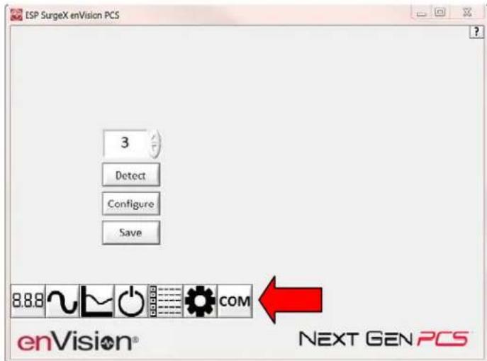
ii. Detect: Automatically detect the COM Port when the enVision, Data Interface Cable, and PC are properly connected and powered up.
iii. Configure: Automatically configure the advanced settings of the Data Interface Cable. May require running the software with elevated permissions (right-click program shortcut and choose "Run As Administrator") on Windows Vista/7/8/10 with UAC (User Account Control) enabled.
iv. Save: Saves the COM Port selection.
5. Command Line Operation
Usage: ESP_SurgeX_Diagnostic_Tool (/o output_file) [-a] [-t] [-c] [-m]
Example : ESP_SurgeX_Diagnostic_Tool /o C:\Users\Robert\Desktop\log.txt -a -m
| Option | Meaning |
| -a | Append output file. If output file already exists, column headers will not be written. |
| -t | Write Timestamped data. |
| -c | Write Event Counts. |
| -m | Write Measurements. |
| If neither -t, -c, nor -m is specified, all will be written. | |
| If -a is not specified, output file will be overwritten. | |
VI. TROUBLESHOOTING
The Filter and Data Interface Cable contain no user-serviceable parts. Do not attempt product disassembly, as this will void the product warranty.
| Symptom | Possible Cause | What To Do |
| Red LED On, Green LED Off, No power at output. | Incorrectly wired branch circuit outlet. The LCD EVENT MONITOR will display the nature of the wiring fault. | Contact a licensed electrician to correct the branch circuit outlet wiring. |
| Red LED Off, Green LED Off, No power at output. | No voltage or unacceptable voltage at branch circuit outlet, or enVision PCS Filter output manually turned Off. | If the LCD EVENT MONITOR is not on, there is no power at the wall receptacle. If the voltage is unacceptable, the LCD EVENT MONITOR will display the type of voltage condition. Use the Diagnostic Software to measure the voltage at the wall receptacle. Contact a licensed electrician to troubleshoot the wall receptacle. Use the Diagnostic Software to manually turn the outlets On. |
| Red LED Off, Green LED On, No power at output. | Defective product. | Contact ESP for product replacement at 800.645.9721. |
2. Software
| Symptom/Error Message | Possible Cause | What To Do |
| Unable to automatically determine COM Port | Data interface cable not properly connected, or EV is not connected to AC mains. | Check interface cable connections at PC and EV. Ensure that EV is powered by AC mains. |
| COM Port not successfully configured. | Windows User Account Control has prevented the software from automatically modifying the COM Port settings in the system registry. | Exit the software, right-click the desktop shortcut, and select “Run As Administrator” or select “Troubleshoot Compatibility” and follow the wizard. |
| Unable to locate or read dictionary file. | One or more language dictionary files cannot be found in the installation directory. | Uninstall the software, and then reinstall the latest version. |
| Problem communicating with EV. | Data interface cable not properly connected, or EV is not connected to AC mains. | Check interface cable connections at PC and EV. Ensure that EV is powered by AC mains. |
| COM Port Settings are not correct, which may result in non-optimal operation. | The COM Port has not been properly configured. | Configure the COM Port following the steps listed in the Configure the Data Interface Cable and COM Port section of this manual. |
| Wrong or corrupt file. | A file import operation has been attempted with an invalid or corrupt data file. | Select a valid data file for import. |
VII. SPECIFICATIONS
| Parameter | Specification | ||
| Load Rating | EV-12010 BR | 10 Amps at 120 Volts | |
| EV-12015 | 15 Amps at 120 Volts | ||
| EV-12016 BR | 16 Amps at 120 Volts | ||
| EV-12020 | 20 Amps at 120 Volts | ||
| EV-20815 | 15 Amps at 208-240 Volts | ||
| EV-20816 BR | 16 Amps at 208-240 Volts | ||
| EV-20820 | 20 Amps at 208-240 Volts | ||
| EV-20830-(L)630(-GNS) | 30 Amps at 208-240 Volts | ||
| EV-23010 | 10 Amps at 240 Volts | ||
| EV-23016 | 16 Amps at 240 Volts | ||
| EV-23016-F | 16 Amps at 240 Volts | ||
| EV-23030-GNS | 30 Amps at 240 Volts | ||
| Voltage Protection Rating (VPR) | EV-12010 BREV-12015EV-12016 BREV-12020 | 330V All Modes | |
| EV-20815EV-20816 BREV-20820 | 700V All Modes | ||
| EV-20830-(L)630(-GNS) | 500V Line-Line600V Line-Ground | ||
| EV-23010EV-23016EV-23016-FEV-23030-GNS | NA | ||
| Attenuation | Normal Mode | All | >30 dB 80kHz - 50MHz |
| Common Mode | EV-12010 BREV-12015EV-12016 BREV-12020 | >30 dB 70kHz - 50MHz | |
| EV-20815EV-20816 BREV-20820EV-23010EV-23016EV-23016-F | >30 dB 200 kHz - 50MHz | ||
| EV-20830-(L)630(-GNS)EV-23030-GNS | >30 dB 200 kHz - 20MHz | ||
| Power Requirement(no load) | EV-12010 BREV-12015EV-12016 BREV-12020EV-20815EV-20816 BREV-20820EV-23010EV-23016EV-23016-F | 4 Watts | |
| EV-20830-(L)630 | 6 Watts | ||
| EV-20830-L630-GNSEV-23030-GNS | 9 Watts | ||
** Specifications subject to change without notice
** All listed specifications obtained at an ambient temperature of 25°C
| Parameter | Specification | |
| Under-Voltage Shutdown | 120V Models | Adjustable from 0 V to 110 V. Default 80 V. |
| 208-240V Models | Adjustable from 0 V to 220 V. Default 160 V. | |
| Under-Voltage Record | 120V Models | Adjustable from 0 V to 110 V. Default 100 V. |
| 208-240V Models | Adjustable from 0 V to 220 V. Default 180 V. | |
| Under-Voltage Restore | 120V Models | Adjustable from 80 V to 110 V. Default 105V. |
| 208-240V Models | Adjustable from 80 V to 220 V. Default 190 V. | |
| Over-Voltage Shutdown | 120V Models | Adjustable from 130 V to 160 V. Default 150 V. |
| 208-240V Models | Adjustable from 220 V to 300 V*. Default 280 V. | |
| Over-Voltage Record | 120V Models | Adjustable from 130 V to 160 V. Default 145 V. |
| 208-240V Models | Adjustable from 220 V to 300 V*. Default 270 V. | |
| Over-Voltage Restore | 120V Models | Adjustable from 130 V to 160 V. Default 140 V. |
| 208-240V Models | Adjustable from 220 V to 300 V*. Default 260 V. | |
| Internal Memory Capacity | 512 Power Quality Events with Timestamp138 Day Electrical Parameter History at 30 minute intervals2.25 Day Electrical Parameters at 10 second intervals | |
| Timestamp Accuracy | ± 1% Typical Product Accuracy | |
| Measurement Accuracy | 120V Models | ± 2% Typical product accuracy |
| 208-240V Models | ± 2% Typical product accuracy | |
| Response Time | Over-Voltage | 90 ms |
| Under-Voltage | 200 ms | |
| Power Outage Event Definition | AC Voltage has dropped below 20V | |
| Surge Event Definition | Filter has been exposed to a transient voltage in one of the 3 possible modes (between Live and Neutral, between Live and Ground, between Neutral and Ground) with a peak amplitude of 500V* or higher and a frequency of 20 kHz or higher. *500V surge voltage amplitude applies to IEEE C62.41 Category B Impulse; surge voltage amplitudes necessary for detection of other surge types may vary. | |
| Modem/Fax Protection | Single telephone line surge suppression | |
| Ethernet Protection | CAT6 network surge protection | |
| Dimensions | 10-20A Models | 6.125" W x 8.375" D x 2" H |
| 30A Models | 7.75" W x 4" D x 11.25" H | |
| Weight | 10-20A Models | 2.25 lbs. |
| 30A Models | 10 lbs. | |
| Temperature Range | 5C to 35C | |
| Humidity Range | 5% to 95% R.H. Non-condensing | |
| Agency Listings | EV-12015 | ETL Certified to UL 1449 3rd Edition |
| EV-12020 | ETL Certified to UL 1283 5th Edition | |
| EV-20815 | ETL Certified to CSA 22.2 No. 8-M1986 (R2008) | |
| EV-20820 | ||
| EV-20830-(L)630(-GNS) | ||
| EV-12010 BR | Tested per UL1449,4th Ed.,Dated August 20,2014 | |
| EV-12016 BR | ||
| EV-20816 BR | ||
| EV-23010 | TUV Certified to IEC 60950-1:2005 (Second Edition) + Am 1:2009 + Am 2:2013 | |
| EV-23016 | ||
| EV-23016-F | ||
| EV-23030-GNS | ||
* The allowed range was changed from 260-300V to 220-300V in firmware version 1.JB3, released in December 2016.
** Specifications subject to change without notice
** All listed specifications obtained at an ambient temperature of 25°C
- User Manual
- AMETEK®
- ELECTRONIC SYSTEMS PROTECTION
- PRODUCT OVERVIEW....4
- INSTALLATION INSTRUCTIONS....5
- HARDWARE....8
- SOFTWARE INSTALLATION .... 13
- USING THE SOFTWARE....14
- Key Features:
- Technical Support:
- INSTALLATION INSTRUCTIONS
- Filter Installation:
- d. Connect Equipment
- HARDWARE
- Filter
- i. Normal Operation
- ii. Wiring Fault
- iii. Abnormal Voltage
- b. Clearing Memory:
- ii. Diagnostic Software:
- Data Interface Cable
- a. Overview
- b. Instructions for Data Retrieval
- c. Instructions for EV-23010/EV-23016 Data Retrieval
- SOFTWARE INSTALLATION
- Computer Requirements
- Hardware Requirements
- Download and Install Software
- Android App Download
- Install Data Interface Cable
- USING THE SOFTWARE
- Physical Connections
- Start the Software
- Configure the Data Interface Cable and COM Port
- c. Click Detect.
- Software Modes
- a. Multimeter Mode
- c. Chart Mode
- d. Outlet Control Mode
- e. Historical Data Mode
- i. Time Stamped Power Quality Event Data
- ii. Historical Electrical Parameter Data
- Average Power Graph
- Average Voltage Graph
- Max/Min Graph
- iv. Import Data
- f. Settings Mode
- g. COM Port Setup Mode
- Command Line Operation
- TROUBLESHOOTING
- Software
Brand : SurgeX
Model : enVision
Category : Uncategorized