SEQ-1U - Uncategorized SurgeX - Free user manual and instructions
Find the device manual for free SEQ-1U SurgeX in PDF.


| Product Type | Programmable AC Power Sequencer / Surge Eliminator / Power Conditioner |
| Model | SEQ-1U |
| Dimensions | 19" W x 12.25" D x 1.75" H (1 RU) |
| Weight | 13 lb (5.9 kg) |
| Input Voltage | 120 VAC, 20 A maximum load |
| Receptacles | 8 total: 2 sequenced banks of 2 (banks A, B, C) + 2 always-on |
| Bank C Configurable | Can be set to always-on or sequenced |
| Surge Protection Rating | A-1-1 (highest federal commercial endurance standard) |
| Inrush Current Elimination | SurgeX ICE® circuitry eliminates inrush issues |
| EMI/RFI Filtering | Normal mode >30 dB (100 KHz - 50 MHz); Common mode >20 dB (1 MHz - 50 MHz) |
| Programmable Delays | Power-up and power-down delays for each bank, 1-40 seconds each |
| Remote Control Inputs | Accepts 5-30V DC, contact closure, or switch (momentary/latching/separate up/down) |
| Over-Ride Input | Forces unit on or off via DC voltage or contact closure |
| 12V DC Output | Programmable, up to 40 mA (for LEDs, relay, or control) |
| Auxiliary Relay | Normally-open contacts, 30V DC / 1A rating |
| Display | Two-line back-lit LCD showing status and line voltage |
| AC Voltmeter | Built-in peak-reading type, accuracy ±2% |
| Voltage Shutdown | Adjustable under-voltage (90-110V) and over-voltage (130-150V) |
| Self-Test Monitoring | Continuous surge protection verification; can trigger shutdown on failure |
| Password Protection | Optional up to 6 letters to prevent unauthorized programming access |
| Power Fail Restore | Optional automatic restart after power failure |
| Ganging / Cascading | Supports connecting multiple SEQs for larger systems |
| Safety Certifications | UL 1449 3rd Edition, UL 1283 5th Edition, CSA C22.2 No.8 (pending for SEQ-1U) |
| Operating Temperature | 5°C to 35°C |
| Humidity Range | 0% to 95% R.H., non-condensing |
Frequently Asked Questions - SEQ-1U SurgeX
User questions about SEQ-1U SurgeX
0 question about this device. Answer the ones you know or ask your own.
Ask a new question about this device
Download the instructions for your Uncategorized in PDF format for free! Find your manual SEQ-1U - SurgeX and take your electronic device back in hand. On this page are published all the documents necessary for the use of your device. SEQ-1U by SurgeX.
USER MANUAL SEQ-1U SurgeX
SEQ / SEQ-1U


Programmable Sequencer/ Surge Eliminator/Power Conditioner
User Manual
Software Version: 2.0
Patents and Published Patent Applications – The Product may be covered by one of more of the following patents or published patent applications:
U.S. Patent Nos: RE39,446; 6,728,089; 6,744,613; 6,947,266; 7,068,487; 7,184,252; 7,511,934; 7,541,696; and 7,551,412. U.S. Patent Application Publication Nos.: 20090303648; 20110063759; 20110102052; 20120128078; 20120130658; and 20120194955.
Canadian Patent No. 2,461,332 and Canadian Patent Application No. 2,511,695 European Patent Application Nos. EP2482085 and EP 2469554
Trademarks and Service Marks


ESP
ECOMMANDCENTER
DIGITAL QC
ELIMINATOR SERIES
ICE
ADVANCED SERIES MODE
ENERGY INTELLIGENCE
NEXT GEN
SURGEX
SURGE ELIMINATION
INRUSH CURRENT ELIMINATION
AXESS
MULTI-STAGE
PCS
DEFENDER SERIES
SERIES MODE
COUVS
CERVELLA
- Introduction 4
- Features 3
- Installation 3
3.1 120 Volt Connections 3
3.2 Remote Control Connections 4
3.2.1 Up/Down Sequence Control Inputs 4
3.2.2 Over-ride Input 5
3.2.3 External LED Connections 5
3.2.4 Confirmation Connection 5
- Quick Start 6
- Programming 7
5.1 Power Sequencing Control 7
5.2 Over-ride Control 8
5.3 Front Panel Push Button 8
5.4 12V DC Output 9
5.5 Auxiliary Relay 10
5.6 Out-of-Range AC Voltage Shut Down 10
5.7 Self-Test Failure Shut Down 11
5.8 Restore Functions 11
5.9 Password 11
- Applications 12
6.1 General Points 12
6.1.1 Controlling the SEQ 12
6.1.2 12V DC Output 12
6.1.3 Auxiliary Relay 13
6.1.4 Over-ride Function 13
6.1.5 Other Functions 13
6.2 Single Unit Systems 14
6.3 Expanded System 15
6.4 Ganged System 18
6.5 Cascaded System 19
- Troubleshooting 20
- Error Codes 20
- Specifications 21
1. Introduction
The SurgeX® SEQ and SEQ-1U are 120V/20 Amp three-bank AC power sequencers incorporating SurgeX® Advanced Series Mode® power conditioning and surge protection. The surge protection is rated A-1-1, the highest standard of the Federal Commercial Item Description for Endurance.
| Model | Size | Sequence Bank A Receptacles | Sequence Bank B Receptacles | Sequence Bank C Receptacles | Always On Receptacles | Total Receptacles |
| SEQ | 2 RU | 4 | 4 | 4 | 2 | 14 |
| SEQ-1U | 1 RU | 2 | 2 | 2 | 2 | 8 |
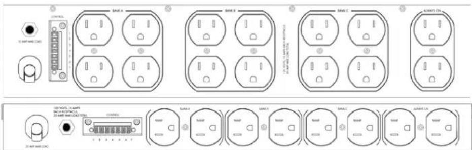
Bank C (which is next to the two always-on receptacles on the rear panel) can itself be configured to be always on, increasing the number of always-on receptacles.
SurgeX ICE® Inrush Current Elimination circuitry is incorporated into the SEQ. This eliminates problems associated with inrush currents from large loads such as amplifiers. With SurgeX ICE® it is not necessary to take inrush currents into account when designing the AC power for a system, and special time-delay circuit breakers are not required: you only need to ensure that the steady-state currents of all products plugged into the SEQ are within the 20 Amp rating.
The front panel houses a two-line back-lit LCD display which provides status information in normal use and allows interaction with menu items during programming. Also on the front panel are two screwdriver-accessible rotary encoders which are used to step through and select from a menu of items which determine the operation of the unit. The push button, when pressed, causes the unit to power up or power down. This button can be disabled if not required. The LED above the button indicates the status of the unit. When the LED is off the unit is fully powered down; when it is on the unit is fully powered up; when it is flashing the unit is in the process of powering up or down.
A built-in AC voltmeter indicates the line voltage on the LCD display. The internal voltmeter is a peak reading type which was chosen because most electronic equipment incorporates a power supply that charges mostly during the AC peaks. Monitoring the peak of the AC provides a more useful indication of the real voltage available to the electronic equipment plugged into the SEQ.
The SEQ is microprocessor controlled and designed to be versatile and expandable. Two or more SEQs can be connected together to provide control and power conditioning for larger systems. The SEQ can also control other SurgeX products with its auxiliary relay contacts and/or its 12V dc output. All options are set via the front panel and all connections are made at the rear panel. An optional password of up to six letters may be specified, preventing unauthorized access to set-up information. All set-up information is stored in non-volatile memory.
A plug-in Phoenix terminal block on the rear panel accommodates the remote control connections and also the low-voltage outputs. There are three inputs which control sequencing; one programmable 12V dc output; and one programmable auxiliary relay providing normally-open contacts. The inputs can be controlled by an applied DC voltage from 5V to 30V, by a contact closure, or by different types of switch; the input selection being made during programming. The inputs and 12V output are designed to withstand incorrect connections including polarity reversal and shorts.
2. Features
- Unsurpassed SurgeX ^ Advanced Series Mode ^ surge elimination
- SurgeX ^ Impedance Tolerant ^ EMI/RFI filtering
- SurgeX ^ ICE ^ Inrush Current Elimination
• All-time delays and functions easily programmed from the front panel
• Bank C can be configured as always on
• Accepts both DC voltage and contact closure control inputs - Two or more units can be ganged or cascaded together for larger systems
- Programmable auxiliary relay output can be used to control other SurgeX® products
- Programmable 12 Volt DC output can be used to control other SurgeX® products or drive LEDs
• Auxiliary relay or 12 Volt DC output can be programmed to provide confirmation feedback
• Built-in AC Voltmeter - Separate over-ride input can be used to force unit off or force unit on
- Optional password can be used to prevent unauthorized access to set-up information
- Adjustable under-voltage and over-voltage shut-down
• Optional restore after power failure feature
3. Installation
The SEQ is designed to be installed in a 19 inch equipment rack and requires two units (2RU) of rack space. Use the four thumbscrews (included) to secure the rack ears to the rack rails. These screws can be tightened by hand and do not require tools.
The SEQ-1U is designed to be installed in a 19 inch equipment rack and requires one unit (1RU) of rack space. Use the eleven flathead screws (included) to secure the left and right rack ears to the product. Use the four thumbscrews (included) to secure the rack ears to the rack rails.
Connect power to the unit by plugging the cord into a 120VAC, 20 Amp wall or floor receptacle. Do not plug the unit into a re-locatable power tap.
3.1 120 Volt Connections
The SEQ has a total of 14 receptacles: three sequenced banks of four, and two always on.
The SEQ-1U has a total of 8 receptacles: three sequenced banks of two, and two always on. Each receptacle is rated for a maximum load of 15 Amps but the total load must not exceed 20 Amps. Plug the equipment cords into the receptacle banks as needed to turn on equipment in the required sequence. The “always on” receptacles provide power as long as power is supplied to the SEQ. Bank “A” always powers up first and off last.
3.2 Remote Control Connections
Remote connections are wired to the green 7-pin plug-in Phoenix terminal block on the rear of the unit next to the power cord. The terminal block itself is shipped in the accessory bag. After you have made the connections to the terminal block, plug it into the connector on the rear of the unit. Never solder (tin) wires before inserting in a terminal block – solder creeps and you will eventually have loose connections!
The connections are shown here:
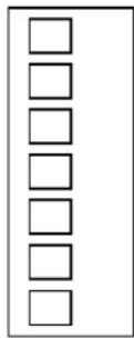
Pin 1 – Up Input
Pin 2 – Down Input
Pin 3 – Over-Ride Input
Pin 4 – 12 V DC Output
Pin 5 - Common
Pin 6 – Aux Relay Contact
Pin 7 – Aux Relay Contact
3.2.1 Up/Down Sequence Control Inputs
The SEQ can be controlled by a DC voltage in the range of 5V to 30V, by a contact closure (such as a relay), or by a switch. In this manual the terms "momentary" and "latching" are used when describing switches. A momentary switch is considered to be a switch which provides a connection only while it is actually held pressed, and a latching switch is considered to be a switch which remains in either the on or the off state (like a light switch). Momentary switches are preferred for use with the SEQ since multiple control locations can be used, and also because some of the functions of the SEQ are not available when a latching switch is used (see programming section). Switches with gold contacts are recommended for the best long-term reliability. The type of input is selected totally through programming, making the electrical connections straightforward. The six control options are discussed below:
a) DC VOLTAGE: The SEQ will power up when the voltage is present and power down when there is no voltage. Connect the positive wire to the "Up" input, and the ground (or negative) wire to "Common". Program the input for "5-30 V DC".
b) CONTACT CLOSURE: The SEQ will power up when the contacts are closed and power down when the contacts are open. Connect the two wires from the contacts to "Up" and "Common". Program the input for "Latching".
c) MOMENTARY SWITCH(ES): The SEQ will power up when a switch is pressed once and power down when a switch is pressed a second time. Connect the two wires from the switch(es) to "Up" and "Common". Program the input for "Momentary".
d) SEPARATE UP & DOWN SWITCHES: The SEQ will power up when the UP switch is pressed and power down when the DOWN switch is pressed. Connect the two wires from the UP switch to "Up" and "Common", and the two wires from the DOWN switch to "Down" and "Common". Program the input for "Separate Up & Down".
e) CENTER-OFF SWITCH: The SEQ will power up when the switch is pressed to the UP position and power down when the switch is pressed to the DOWN position. Connect the wire from the UP terminal to "Up", the wire from the DOWN terminal to "Down", and the wire from the COMMON terminal to "Common". Program the input for "Separate Up & Down".
f) LATCHING SWITCH: The SEQ will power up when the switch is closed and power down when the switch is open. Connect the two wires from the switch to "Up" and "Common". Program the input for "Latching".
Note: The front panel button will not operate with options a, b or f
3.2.2 Over-Ride Input
The SEQ has the option of adding an over-ride function for purposes such as providing fire safety over-ride to force the system either on or off. An over-ride is initiated by applying a dc voltage of 5-30V or by a sustained contact closure. The selection of dc voltage or contact closure is accomplished during programming. This topic is covered fully in the programming section.
Connect the over-ride signal to the "over-ride" input and "common". In the case of a dc voltage, connect the positive wire to "over-ride" and the negative wire to "common".
3.2.3 External LED Connections
The SEQ is able to drive external LEDs or other signaling devices through its 12V DC output which can provide up to 40mA of current. External LEDs connected in this way will mimic the LED on the front panel. When connecting LEDs to the 12V output, a series resistor is required. For example, many LEDs work well with 10mA of current, so a 1K resistor is usually a good choice. If more than one LED is required, then use a separate series resistor for each LED. In this example, four external LEDs could be powered at 10mA each from one SEQ. If more than four LEDs are required, it will be necessary to increase the series resistor so that the total load is not more than 40mA.
Connect each LED anode to "12V DC output" through a resistor, and the cathodes to "Common". Program the 12V DC Output for "LED". This causes LEDs connected to the SEQ to flash while the unit is powering up or powering down in the same manner as the front panel LED.
3.2.4 Confirmation Connection
The SEQ offers two ways to provide confirmation feedback to a central controller: a 12V DC output and isolated relay contacts. Confirmation tells the controller that the SEQ has indeed powered up or that it is fully powered down. If the 12V DC output and the Aux Relay contacts are not used for any other function, you will be free to choose whichever provides the best interface for the application. However, if one of these outputs is used for another function you will have to use the one that is available.
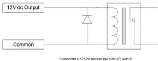
To use the 12V DC output for confirmation, connect “12V DC output” to the positive input of the controller and “Common” to ground. The output will be at 12V when all banks are powered up and will be zero when all banks are powered down. Program 12V DC Output for “Confirm”. Note that the SEQ common terminal is shared between the inputs and the 12V DC output. If you need relay contacts for confirmation and you are using the Aux Relay for another function you can connect a small relay between the 12V DC output and common. The relay coil current must not be more than 40mA, and you must connect a diode such as a 1N4148 or 1N4002 across the relay coil (cathode to +12V dc) to suppress the back-EMF from the coil. If you need assistance with this please contact our technical support department.
To use the Auxiliary Relay contacts for confirmation, connect the contacts to the input of the controller.
The relay contacts will be closed when all banks are powered up and open when all banks are powered down. The default for menu item “Aux Output” is “Confirm” so you do not need to program this item unless you previously changed it. The contacts are rated for 30V DC at 1 Amp.
4. Quick Start
This section is intended to allow users with a simple straightforward system incorporating a single SEQ to get up and running with minimum effort. If this is not the case then skip this section and go directly to the section on detailed programming (Section 5). If you are going to follow the quick start instructions, you only need to perform the following steps since the unit has been shipped with default settings suitable for basic operation.
- Make all connections as per Section 3.
- Insert a screwdriver in the hole labeled SEL and turn it one click clockwise. Press the front panel button and you will see the first menu item "Bank C Function" on the display. Leave this set to Sequence unless you want to use Bank C as Always On receptacles. In that case insert the screwdriver in the hole labeled ADJ and turn one click clockwise to change it to Always On.
- Advance SEL one click to get the second menu item "Up & Down Inputs". Select the option required for the install by referring to section 3.2.1 and set the option by rotating ADJ.
- Advance SEL one more click. You will now be able to set the first delay time which is for bank A powering up. Use ADJ to set the required delay time in seconds.
- Advancing SEL one click at a time and using ADJ to adjust the delay times, set the remaining five delay times: B on, C on, A off, B off, C off. If you have set Bank C to be Always On skip the delay settings for Bank C.
- If you have connected an LED to the 12V DC output for remote signaling, step through the menu until you reach "12V DC Output". Then advance ADJ to select "LED". This selection will make the remote LED mimic the LED on the front panel which flashes while the unit is powering up or powering down.
- Turn SEL fully counter-clockwise and press the button to exit programming.
Although the above steps are all that are required to get the SEQ running, you may want to take a look at the following programming options to see if you want to make use of any of these functions. You will find these listed on the reverse side of the Programming and Connection Guide, and they are near the end of the menu that you step through by turning SEL.
| Programming Option | Description |
| Low Voltage Shutdown | Shuts unit off if AC voltage drops below the set point |
| High Voltage Shutdown | Shuts unit off if AC voltage rises above the set point |
| Self-Test Shutdown | Shuts down unit if self-test fails |
| Power Fail Restore | Turns unit back on after a power failure if unit was powered up when the power failed |
5. Programming
The SEQ is a very versatile sequencer and has 25 menu items that control its operation. Some menu items allow predetermined options to be selected and others allow time delays or voltage limits to be adjusted. All adjustments are made via the front panel and are achieved by turning the two screwdriver-accessible rotary encoders labeled SEL (select) and ADJ (adjust). Turning SEL steps through the menu (shown on the first line of the display), and turning ADJ allows each menu item to be changed (shown on the second line of the display).
To enter the programming mode first turn SEL one click clockwise. The display will then tell you to press the front panel button. This puts you into the programming mode. All the options, delay times and voltage adjustments are set using this mode. When you have completed the set-up turn SEL counter-clockwise until the display tells you to press the button again. Doing so saves the new set-up information in non-volatile memory and puts you back into normal operation.
A password can be set while in the programming mode. Once a password has been set, you need to enter the same password before you can get back into the programming mode again. This prevents unauthorized personnel from changing the set-up information. The password option is the last menu item and can be from one to six letters (A-Z).
You must be sure to remember the password once it is set as the only way to erase it is to erase all the set-up information stored in the non-volatile memory. Please consult the factory to get instructions if you ever need to do this.
The instructions and notes that follow are in the same order as the actual menu items.
5.1 Power Sequencing Control
The following eight menu items must be set before the SEQ can be used in a system. These determine the function and delay times of the sequenced banks, and the type of control input: DC voltage, contact closure or switch. Please see Section 3.2.1 for details.
| Menu Item | Options | Description |
| Bank C Function | Sequence | Bank C is sequenced normally |
| Always On | Bank C is no longer sequenced On and Off | |
| Up & Down Inputs | Momentary | Use with momentary switch(es) |
| Separate Up & Down | Use with separate switches for Up and Down | |
| Latching | Use with a latching switch or contact closure | |
| 5-30V DC | Use with an applied DC voltage of 5 to 30 Volts | |
| Delay A, B, C On | 1 – 40 Seconds | Set power-up delay time for each bank |
| Delay A, B, C Off | 1 – 40 Seconds | Set power-down delay time for each bank |
5.2 Over-Ride Control
The SEQ has an optional over-ride and four menu items that control this function. If you do not require an over-ride, you can skip the next four menu items since units are shipped with this function disabled. The over-ride can be used for such purposes as fire safety over-ride, and can be set to either force the unit on or force it off when an over-ride signal occurs. The over-ride input is also used for feedback when two or more SEQs are cascaded together. This is covered in the applications section.
| Menu Item | Options | Description |
| Over-Ride Input | Contact Closure | Use with relay contacts or latching switch |
| 5 – 30V DC | Use with an applied DC voltage of 5 to 30 Volts | |
| Over-Ride Func | Disable | Disable over-ride if not required |
| Force On | Force unit On when over-ride is applied to input | |
| Force Off | Force unit Off when over-ride is applied to input | |
| Master | Use when unit is the master in a cascaded chain | |
| Pass-Thru | Use when unit is an intermediate unit in a chain | |
| Over-Ride Option | Use Main Delays | The main delays are used when an over-ride occurs |
| Special Delay | The special delay is used when an over-ride occurs. A special delay should not be used when the Aux Relay is used to provide a fourth sequenced bank, as the sequencing between the fourth bank and the three main banks during an over-ride may not coordinate correctly. | |
| Over-Ride Delay | 0 – 30 Seconds | Set delay time to be used only during an over-ride |
5.3 Front Panel Push Button
The front panel push button allows the unit to be powered up or powered down from the front panel. There is one menu item associated with the push button which allows it to be disabled or to operate only after a one second delay. The delay option prevents the unit inadvertently powering on or off if the push button is accidentally bumped. Note that the push button cannot be used in conjunction with applied voltage or latching type remote control inputs.
| Menu Item | Options | Description |
| Front Panel Button | Enable | Front panel button is enabled |
| Delay | Button has a 1 second delay | |
| Disable | Front panel button is disabled |
5.4 12V DC Output
The programmable 12V DC output provides a nominal 12 Volts at up to 40mA of direct current and is available at the rear of the unit. The 12V DC output can be used to provide confirmation to a central controller, to control another power distribution product, to drive LEDs, or to provide feedback to the previous SEQ in a cascaded chain. Please see the applications section for full details on setting up an expanded system. There are three menu items to control the 12V DC output: one to select the mode of operation, and two to set the delay times. The two delay times are only applicable when option A, B, or C is selected for 12V DC Output. There is additional information on the 12V DC output in Sections 3.2.3 and 3.2.4. If the DC output is not used it can be left at any setting.
| Menu Item | Options | Description |
| 12V DC Output | Confirm | Output provides confirmation to a controller |
| A | Output synchronized with Bank A | |
| B | Output synchronized with Bank B | |
| C | Output synchronized with Bank C | |
| LED | Flashes while powering Up and Down to drive LEDs | |
| Cascade | Provide feedback to the previous cascaded unit | |
| 12V Delay On | 0 – 40 Seconds | Set power-up delay time when set to A, B, or C. This delay time begins with the same internal trigger as the bank selected in the previous item. For example, if you wanted a fourth bank to power on first and off last, you should select A as the 12V DC Output and set this delay time to be shorter than the delay that you set for Main Bank A On (the 12V Delay On can be set to zero in this case); or if you wanted a fourth bank to power on last and off first, you should select C as the 12V DC Output and set this delay time to be longer than the delay that you set for Main Bank C On. |
| 12V Delay Off | 0 – 40 Seconds | Set power-down delay time when set to A, B, or C. This delay time begins with the same internal trigger as the bank selected in 12V DC Output. For example, if you wanted a fourth bank to power on first and off last, you should select A as the 12V dc Output and set this delay time to be longer than the delay that you set for Main Bank A Off; or if you wanted a fourth bank to power on last and off first, you should select C as the 12V DC Output and set this delay time to be shorter than the delay that you set for Main Bank C Off (the 12V Delay Off can be set to zero in this case). |
5.5 Auxiliary Relay
The programmable Auxiliary Relay provides a single normally-open contact which is available at the rear of the unit. The aux relay can be used to provide confirmation to a central controller, to control another power distribution product, or for controlling another SEQ when two or more are ganged or cascaded together. Please see the applications section for full details on setting up an expanded system. There are three menu items to control the aux relay: one to select the mode of operation, and two delay times. The two delay times are only applicable when option A, B, or C is selected for Aux Output. There is additional information on the aux relay in section 3.2.4.
| Menu Item | Options | Description |
| Aux Output | Confirm | Relay contacts provide confirmation to a controller |
| A | Contacts synchronized with Bank A | |
| B | Contacts synchronized with Bank B | |
| C | Contacts synchronized with Bank C | |
| Gang | Provide control to the next ganged unit | |
| Cascade | Provide control to the next unit in a cascaded chain | |
| Aux Delay On | 0 – 40 Seconds | Set power-up delay time when set to A, B, or C. This delay time begins with the same internal trigger as the bank selected in the previous item. For example, if you wanted a fourth bank to power on first and off last, you should select A as the Aux Output and set this delay time to be shorter than the delay that you set for Main Bank A On (the Aux Delay On can be set to zero in this case); or if you wanted a fourth bank to power on last and off first, you should select C as the Aux Output and set this delay time to be longer than the delay that you set for Main Bank C On. |
| Aux Delay Off | 0 – 40 Seconds | Set power-down delay time when set to A, B, or C. This delay time begins with the same internal trigger as the bank selected in Aux Output. For example, if you wanted a fourth bank to power on first and off last, you should select A as the Aux Output and set this delay time to be longer than the delay that you set for Main Bank A Off; or if you wanted a fourth bank to power on last and off first, you should select C as the Aux Output and set this delay time to be shorter than the delay that you set for Main Bank C Off (the Aux Delay Off can be set to zero in this case). |
5.6 Out-of-Range AC Voltage Shut Down
The SEQ has built-in line voltage monitoring and out-of-range shut down. The default limits are 90V at the low end and 150V at the high end, and the shut down sequence begins if the line voltage remains outside the set limits for 1 second or more. These limits are adjusted by using two menu items, with the low limit adjustable from 90V to 110V and the high limit adjustable from 130V to 150V. If the unit has shut down due to an out-of-range line voltage and the line voltage subsequently returns to normal, the power up sequence will only resume if the Power Fail Restore option (section 5.8) has been set to "Enable".
| Menu Item | Options | Description |
| Low Volt Shut Down | 90 – 110 VAC | Set low voltage shut down point |
| High Volt Shut Down | 130 – 150 VAC | Set high voltage shut down point |
5.7 Self-Test Failure Shut Down
The SEQ circuitry has integral self-monitoring which tells the microprocessor that the surge protection is on-line and operating within specification. This menu item allows an option to be selected so that the unit will begin the power down sequence should the self-test ever fail.
| Menu Item | Options | Description |
| Self-Test Shut Down | Disable | Banks will not be powered off if self-test fails |
| Enable | Banks will be powered off if self-test fails |
5.8 Restore Functions
There are two menu items which, when enabled, allow the SEQ to restore the original "on" condition after shutdown caused either by loss of AC power (or out-of-range AC) or by an over-ride. When these options are disabled, the SEQ will not power up when the condition that caused the shut down goes away. The restore functions cannot be used in conjunction with applied voltage or latching type remote control inputs.
| Menu Item | Options | Description |
| Power FailRestore | Disable | Banks will remain off after a power failure |
| Enable | Restore the original status after a power failure | |
| Over-RideRestore | Disable | Original status will not be restored after an over-ride |
| Enable | Original status will be restored after an over-ride |
5.9 Password
A password can be set which will prevent unauthorized access to the programming mode. From one to six letters, A through Z, can be used as a password.
It is important to remember the password because, once it has been set, you cannot get into the programming mode again without entering the password. If you do forget the password, the only way to erase it is to erase all the set-up information. If you ever need to do this, please call the factory to obtain instructions.
When you select Password in the menu you will see a blinking cursor on the bottom line of the display. Set the first letter of the password by turning ADJ. Then advance SEL one click so that the cursor moves to the next position and repeat the process until you have set all the letters of your chosen password.
To erase a password set the cursor on the first letter and turn ADJ counter-clockwise until you see only the cursor and no letter above it. Then turn SEL one click back. It is not necessary to erase each letter; erasing the first letter erases the whole password.
| Menu Item | Options | Description |
| Password | A - Z | Set optional password of up to six letters. Set each letter with ADJ and advance SEL to go to the next letter. |
6. Applications
The SEQ can be used in four types of configuration: a single unit providing three sequenced banks; an expanded system where the SEQ controls remote turn-on SurgeX products providing four or five sequenced banks (or three banks with increased current capacity on extra units); a ganged system where two or more SEQs are connected together such that they all turn on and off at the same time providing three banks with increased current capacity for all three banks; a cascaded system where two or more SEQs are connected together such that the banks turn on sequentially from one SEQ to the next SEQ. Each configuration is covered separately in its own section, but first there are some general points which apply to all types of installation.
6.1 General Points
This Section provides detailed information about the remote control connections. If you have not already done so, please read Section 3.2 before continuing. The information in Section 6.1 applies to all types of installations and you should also read this section before continuing further.
6.1.1 Controlling the SEQ
The SEQ is primarily designed to be used with momentary action switches. A momentary switch is a switch where the contacts are closed only while the switch is actually pressed, such as a push switch. Using momentary switches allows several switches to be connected in parallel so that the SEQ can be controlled from multiple locations. A single push switch would cause the unit to power-up on the first press and then power down on the second press. A dual momentary switch, such as a center-biased rocker, or two separate push switches (one for UP and the other for DOWN), can also be used with equal versatility. It is up to the installer to choose the configuration. Whatever type of switch is used, switches with gold contacts are recommended for the best long-term reliability.
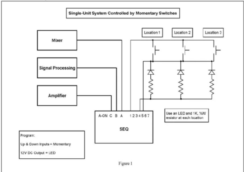
Where there are multiple control locations it is advantageous to use the 12V dc output to drive LEDs so that there is an LED at each control location. Up to four LEDs running at 10mA each can be powered from the 12V dc output. Each control location then has an indication of the operational status of the SEQ regardless of which location last initiated power-up or power-down.
The SEQ also supports latching switches, contact closure and applied DC voltage, but these types of input cannot be used with multiple control locations – they are intended primarily for a small system or for hook-up to a central controller. The front-panel push-button will not work with a latching switch, contact closure or applied voltage inputs.
6.1.2 12V DC Output
The 12V DC output can be used to drive LEDs, thereby showing the operational status at remote control locations. This output can drive up to 40mA which can power four LEDs at 10mA each, or more LEDs at reduced current. A resistor is required for each LED to limit the current. The 12V DC output can also provide confirmation to a central controller or be used to drive a small relay (40mA maximum coil current). The 12V DC output can be configured to control an external bank of equipment as an alternative to or in addition to the Aux Relay. See Section 3.2 for connection details and Section 5.3 for programming details.
The 12V DC output has a special use when SEQs are cascaded together – this is covered in the section on cascaded systems.
6.1.3 Auxiliary Relay
The primary uses of the aux relay are to control other remote turn-on products or to provide status feedback to a central controller to confirm that the unit has completed the requested operation. Details of using the aux relay to control other products are covered in the specific applications sections. The aux relay provides one normally-open contact at the rear terminal block and can handle 1 Amp at up to 30 Volts DC. See Section 3.2 for connection details and Section 5.4 for programming details.
The aux relay has a special use when SEQs are ganged or cascaded together – this is covered in the sections on ganged and cascaded systems.
6.1.4 Over-Ride Function
The SEQ has an over-ride function that can be used for fire safety and other applications where the power must be held on or forced off. The over-ride function is programmable so that it can be set to either force the unit off or force it on. When a signal is applied to the over-ride input the unit will be forced on or off regardless of the main inputs.
If the unit has been forced off by an over-ride, the Over-Ride Restore menu option determines whether the unit will power up again or remain off.
There is a special delay which can be used only with an over-ride condition. This allows a faster turn on (or turn off) than the main delays. It is not recommended to use the special delay with expanded systems because the auxiliary bank may not turn on (or turn off) in the correct sequence during an over-ride condition.
The over-ride input can be programmed to accept either a contact closure or applied DC voltage. See Section 3.2 for connection details and Section 5.2 for programming details.
The over-ride input has a special use when SEQs are cascaded together. This is covered in the section on cascaded systems. If an over-ride is required with a ganged system, use the over-ride input on the first SEQ. If an over-ride is required with a cascaded system, use the over-ride input on the last SEQ.
6.1.5 Other Functions
Reading through the programming section is a good way to understand all the functions and options available in the SEQ. Most of the functions are associated with main operation outlined in this section above. However, there are some other independent functions that can be selected:
The front panel button can be programmed to be operational, non-operational or operate after a one-second delay. Choosing the last setting prevents accidental power-up or power-down. See Section 5.5 for more details.
The SEQ has built-in voltage limits that will cause the unit to power down if the line voltage is outside these limits. The low limit can be set from 90V to 110V and the high limit can be set from 130V to 150V. See Section 5.6 for more details.
The SEQ has internal self-test circuitry that constantly monitors the operation of the unit and displays the word "Good" or "Fail" on the front panel. The unit can be programmed to shut down in the unlikely event that the self-test should fail. See Section 5.7 for more details.
There are two “Restore” options. The first option allows the unit to restore to a power-on state after loss of AC power or out-of-range AC voltage. The second option allows the unit to restore to a power-on state after being forced off by an over-ride. See Section 5.8 for more details.
6.2 Single Unit System
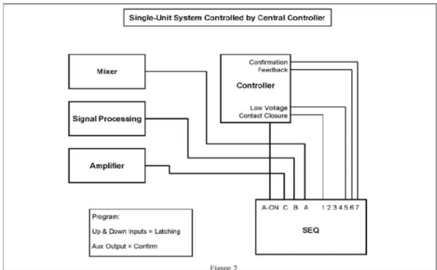
Most of the information necessary to install and set up a single unit system can be found in Sections 3.2 and 6.1. Figure 1 shows a single unit system controlled by momentary switches at three different locations, and Figure 2 shows a single unit controlled by a central controller.
flowchart
graph TD
    A["Signal Processing"] --> B["Mixer"]
    C["Amplifier"] --> D["A-ON C B A 1234567 SEQ"]
    E["Program: Up & Down Inputs = Momentary\n12V DC Output = LED"] --> D
    F["Location 1"] --> G["Resistor"]
    H["Location 2"] --> I["Resistor"]
    J["Location 3"] --> K["Resistor"]
    L["Use an LED and 1K, 1kW resistor at each location"] --> M["Resistor"]
flowchart
graph TD
    A["Mixer"] --> B["Controller"]
    C["Signal Processing"] --> B
    D["Amplifier"] --> B
    B --> E["A-ON C B A 1234567 SEQ"]
    B --> F["Confirmation Feedback"]
    B --> G["Low Voltage Contact Closure"]
    H["Program: Up & Down Inputs = Latching Aux Output = Confirm"] --> B
6.3 Expanded System
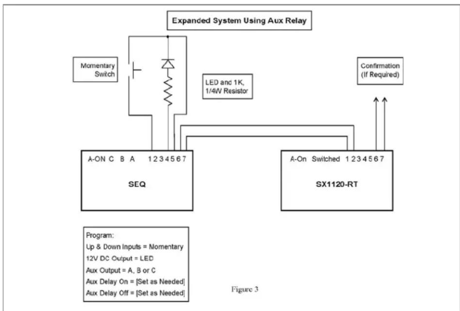
A basic expanded system consists of an SEQ in combination with a remote turn-on SurgeX such as the SX1120-RT or the SX20-NE/RT. Such a system provides a total of four banks and 40 Amps total load capacity. The auxiliary relay inside the SEQ is normally used to control the second unit although the 12V DC output can also be used for this purpose. The only difference in these remote control configurations is that, when the aux relay is used to control a second unit, it cannot be used for confirmation feedback to a central controller, and when the 12V dc output is used for control it cannot be used to drive LEDs.
If more current capability is required, additional SurgeX RT products can be connected to the second unit. Connect pins 6 & 7 of the second unit to pins 1 & 2 of the third unit, and so on.
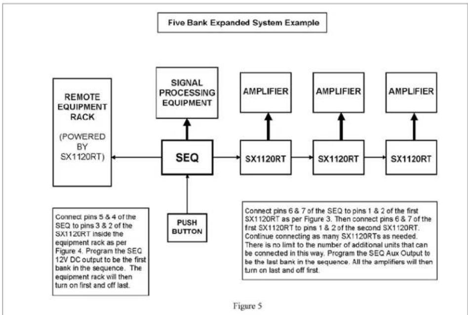
It is possible to configure a five bank expanded system by using both the aux relay and the 12V dc output to simultaneously control two separate pieces of equipment or two racks of equipment. In this case, refer to Figures 3, 4 & 5 and follow the instructions below.
The SEQ in an expanded system can be controlled by the same inputs as a single unit system.
Figure 3 (page 16) shows how the two units are wired together using the aux relay contacts. The aux relay contacts on the SEQ (terminals 6 & 7) are connected to the contact closure inputs at the back of the RT (terminals 1 & 2). In order to work as a 4-bank system the aux relay must be programmed accordingly. The Aux Output menu item must be set to A, B or C. This synchronizes the aux relay to one of the internal triggers used for main banks A, B or C. The Aux Delay On and Aux Delay Off delay times are then set to position the 4^th bank wherever it is required to be in the sequence. As an example: if an SX1120-RT, connected to an SEQ, should turn on last and off first, the menu items shown below should be programmed as follows:
| Menu Item | Setting |
| Delay C On | 5* |
| Delay C Off | 5* |
| Aux Output (or 12V DC Output) | C |
| Aux (or 12V) Delay On | 10* |
| Aux (or 12V) Delay Off | 0 |
| *These delay times are an example. Set actual times as required for each application. | |
In the above example, the turn-on delay for Bank C is 5 seconds and the turn-on delay for the SX1120-RT is 10 seconds. Because the Aux Output is set to Bank C, the same internal trigger is used to start both time delays. What then happens is that after Bank B turns on, there is a 5 second delay before Bank C turns on, then there is further 5 second delay before the SX1120-RT turns on (the 10 second timer started at the same time as the 5 second timer for Bank C). When it is time to power down, the SX1120-RT turns off immediately (the delay is set to zero), then 5 seconds later Bank C turns off.
In another example, if the SX1120-RT should turn on first and off last, the programming would be as follows:
| Menu Item | Setting |
| Delay A On | 5* |
| Delay A Off | 5* |
| Aux Output (or 12V DC Output) | A |
| Aux (or 12V) Delay On | 0 |
| Aux (or 12V) Delay Off | 10* |
| *These delay times are an example. Set actual times as required for each application. | |
As can be seen in the above two examples, by choosing the appropriate sync setting and delay times it is possible to position the 4^th bank anywhere in the sequence.
If an over-ride is used with an expanded system do not use the Special Delay because the 4^th bank may not turn on and off in the correct sequence during an over-ride condition.
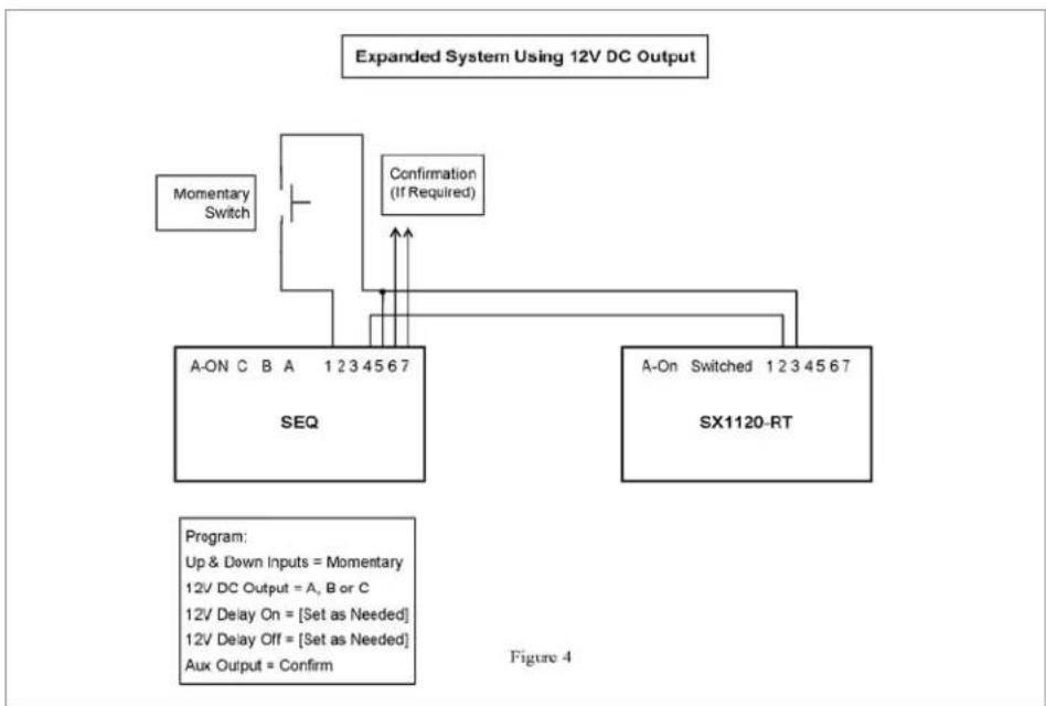
Figure 4 (page 17) shows how to configure an expanded system using the 12V DC output instead of the Aux Relay to control external units. This option allows the aux relay to be used for confirmation but it is then no longer possible to drive external LEDs from the 12V DC output. The programming and delay timing set up follow the same concepts as for the aux relay which is explained above.
Figure 5 (page 17) shows an example of a medium-sized system where the SEQ is controlling two separate sets of equipment independently by using both the aux output and the 12V DC output as control outputs. The equipment rack is controlled by the 12V DC output and the bank of amplifiers is controlled by the aux output (via SX1120RTs). The signal processing equipment is powered from the SEQ itself. Control wiring and programming is as per Figures 3 and 4. Figure 5 is just one example of the versatility of the SEQ, and the banks do not have to be set up exactly as shown in this example. The aux output and the 12V DC output could be programmed to be the first two sequenced banks, or the last two sequenced banks. Similarly, the rack-mount SX1120RT remote turn-on SurgeX was used in this example whereas the ICE20C or the hard-wired SX20-NE/RT could equally have been used.
flowchart
graph TD
    A["Expanded System Using Aux Relay"] --> B["Momentary Switch"]
    B --> C["A-ON C B A 1234567 SEQ"]
    B --> D["A-ON Switched 1234567 SX1120-RT"]
    C --> E["LED and 1K, 1/4W Resistor"]
    D --> F["Confirmation (If Required)"]
    G["Program: Up & Down Inputs = Momentary 12V DC Output = LED Aux Output = A, B or C Aux Delay On = [Set as Needed"] Aux Delay Off = [Set as Needed]] --> H
flowchart
graph TD
    A["Momentary Switch"] --> B["A-ON C B A 1 2 3 4 5 6 7 SEQ"]
    C["Confirmation (If Required)"] --> B
    B --> D["A-On Switched 1 2 3 4 5 6 7 SX1120-RT"]
    E["Program: Up & Down Inputs = Momentary\n12V DC Output = A, B or C\n12V Delay On = [Set as Needed"]\n12V Delay Off = [Set as Needed]\nAux Output = Confirm] --> B
flowchart
graph TD
    A["REMOTE EQUIPMENT RACK\n(POWERED BY SX1120RT)"] --> B["SEQ"]
    C["SIGNAL PROCESSING EQUIPMENT"] --> B
    D["AMPLIFIER"] --> E["SX1120RT"]
    F["AMPLIFIER"] --> G["SX1120RT"]
    H["AMPLIFIER"] --> I["SX1120RT"]
    J["PUSH BUTTON"] --> B
    K["Connect pins 5 & 4 of the SEQ to pins 3 & 2 of the SX1120RT inside the equipment rack as per Figure 4. Program the SEQ 12V DC output to be the first bank in the sequence. The equipment rack will then turn on first and off last."] --> B
    L["Connect pins 6 & 7 of the SEQ to pins 1 & 2 of the first SX1120RT as per Figure 3. Then connect pins 6 & 7 of the first SX1120RT to pins 1 & 2 of the second SX1120RT. Continue connecting as many SX1120RTs as needed. There is no limit to the number of additional units that can be connected in this way. Program the SEQ Aux Output to be the last bank in the sequence. All the amplifiers will then turn on last and off first."] --> B
6.4 Ganged System
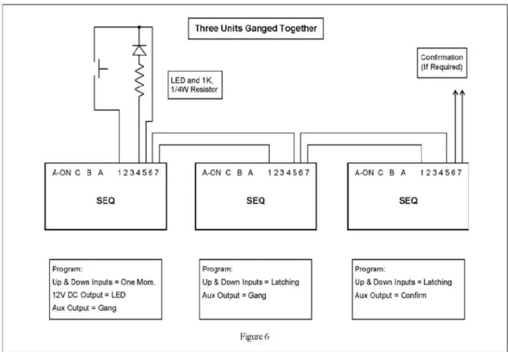
A ganged system consists of two or more SEQs connected together in such a way that they all turn on and off together. Figure 6 shows how to connect and program each unit in a three-unit system. If only two units are to be ganged together then ignore the middle unit in the diagram. If more than three units are to be ganged together then keep the first and last units set up as shown, add units in the middle and set them up and connect them in the same way as the middle unit in the diagram.
The remote control inputs should be connected to the first unit, and the same control options are available as for a single-unit system. If confirmation feedback is required for a central controller, use the aux relay contacts on the last unit.
The delay times should be set the same for all the SEQs unless you want to skew the turn-on or turn-off points from one unit to the next.
If the low and high voltage shutdown points are narrowed from their defaults of 90V and 150V this should be done on the first unit only. The other units should be left set to 90V and 150V. The two restore options should only be enabled (if required) on the first unit. The self-test shutdown should be the same for all units.
If an over-ride is required connect it to the first unit.
flowchart
graph TD
    A["Three Units Ganged Together"] --> B["LED and 1K, 1/4W Resistor"]
    B --> C["SEQ"]
    C --> D["Program: Up & Down Inputs = One Mom. 12V DC Output = LED Aux Output = Gang"]
    C --> E["SEQ"]
    E --> F["Program: Up & Down Inputs = Latching Aux Output = Gang"]
    E --> G["SEQ"]
    G --> H["Confirmation (If Required)"]
6.5 Cascaded System
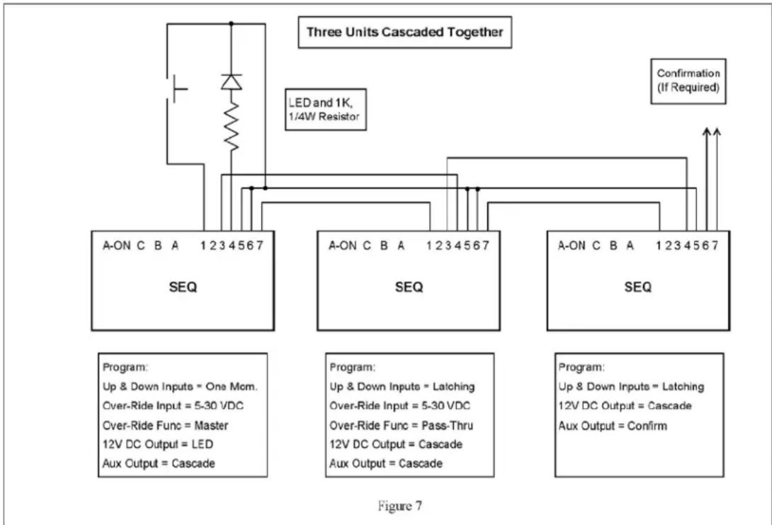
A cascaded system consists of two or more SEQs connected together such that they turn on and off one after another in an extended sequence. Connecting a cascaded system together is a little more complicated than the other types of system because there must be feedback from each unit to the previous unit as well as control from each unit to the next unit. The 12V DC output (terminal 4) is used as the feedback source and the over-ride input (terminal 3) is used as the feedback input. Figure 7 shows how to connect and program each unit in a three-unit system. Note that terminals 5 and 6 are connected together for all units except the last one. If only two units are to be cascaded together, then ignore the middle unit in the diagram. If more than three units are to be cascaded together, then keep the first and last units set up as shown, add units in the middle and set them up and connect them in the same way as the middle unit in the diagram.
The remote control inputs should be connected to the first unit, and the same control options are available as for a single-unit system. If confirmation feedback is required for a central controller, use the aux relay contacts on the last unit.
The delay times should be set as required for the application.
If the low and high voltage shutdown points are narrowed from their defaults of 90V and 150V this should be done on the first unit only. The other units should be left set to 90V and 150V. The two restore options should only be enabled (if required) on the first unit. The self-test shutdown should be the same for all units.
If an over-ride is required connect it to the last unit and program that unit to accept the type of over-ride you need.
flowchart
graph TD
    A["LED and 1K, 1/4W Resistor"] --> B["Three Units Cascaded Together"]
    B --> C["SEQ"]
    B --> D["SEQ"]
    B --> E["SEQ"]
    C --> F["Program: Up & Down Inputs = One Mom. Over-Ride Input = 5-30 VDC Over-Ride Func = Master 12V DC Output = LED Aux Output = Cascade"]
    D --> G["Program: Up & Down Inputs = Latching Over-Ride Input = 5-30 VDC Over-Ride Func = Pass-Thru 12V DC Output = Cascade Aux Output = Cascade"]
    E --> H["Confirmation (If Required)"]
7. Troubleshooting
| Condition | Check |
| Initial Check | Whenever power is applied to the SEQ the LCD display should be illuminated and should show two lines of text as follows:Status: All On or All Off 120VAC (or whatever the actual line voltage is)Protection: GoodIf the first line of the display does not show “Status” the unit is in programming mode and therefore the three banks of receptacles will not turn on. Turn the SEL rotary encoder counter-clockwise and then press the button to get out of programming mode.If the display is not illuminated and showing the above two lines of information check that power is actually being supplied to the unit and that the breaker on the rear panel adjacent to the power cord has not tripped. If you are certain that power is being supplied to the unit, consult the factory for assistance. |
| Unit will not power up from remote control connection | If you have performed initial checks as above and the unit will still not power up it could be because the “down” input (terminal 2) is being held active all the time. Remove the terminal block from the rear and check that the Up and Down signals are correct with a meter. |
| The front panel button will not work | Check whether the front panel button has been programmed to Delay or Disable. If it has been programmed to Delay you must hold the button for one second before it will operate. If it has been programmed to Disable it will not operate at all.The front panel button will not work if the Up & Down Inputs has been set to Latching or 5-30V DC. This is due to the fact that a latching type input will always over-ride a momentary switch like the front panel button. |
| The unit sequences up but will not sequence down | Check the remote control connections using a meter and also the programming of the Up & Down Inputs. If Up & Down Inputs is set to Separate Up & Down and you are using a single momentary switch the unit will sequence up but not sequence down. |
| The unit starts to sequence up but then immediately sequences down | There are two likely causes for this: One cause is a Down input that is on all the time and over-riding the power up sequence. Check the down input with a meter. The other cause is that the Over-Ride Func menu item has been set to Master when the unit is not actually connected to another SEQ and is in cascade mode. Change this menu item to Disable. |
| The unit will not go into programming mode | You must power down the unit first before you can get into the programming mode. |
8. Error Codes
| Error | Error Description |
| Error 05 | The calibration of the AC voltmeter is no longer accurate. The unit is otherwise fully operational. Call the factory for assistance. |
| Error 15 | There is a checksum error in the non-volatile memory. This indicates that the set-up information could be incorrect. It is recommended that you completely check the programming and save the settings again. If Error 15 is still displayed there is most likely a permanent problem with the non-volatile memory. |
| Error 16 | There is an internal error. The unit will need to be returned to the factory for repair. |
| Error 24 | Please call the factory. |
9. Specifications
| Parameter | Specification | ||
| Load Rating | 20 Amps at 120 Volts | ||
| Maximum Load Inrush Energy | 1400 Joules total during power-up | ||
| Surge Let-through Voltage (6000 Volt Surge) | 0 Volts | ||
| UL 1449 Adjunct Classification Test Results | 1000 Surges, 6000 Volts, 3000 Amps, B3 pulse; measured suppressed voltage, 170 Volts; no failures | ||
| Maximum Applied Surge Voltage | 6000 Volts * | ||
| Maximum Applied Surge Current | Unlimited (due to current limiting) * | ||
| Maximum Applied Surge Energy | Unlimited (due to current limiting) * | ||
| Endurance (C62.41-1991 category B3 pulses) | 1 KV > 500,000; 3 KV > 10,000; 6 KV > 1000 | ||
| EMI/RFI Filter | Normal mode (50Ω load) | >30 dB 100 KHz - 50 MHz | |
| Common Mode (50Ω load) | >20 dB 1 MHz - 50 MHz | ||
| Under-Voltage Auto Shutdown | Adjustable from 90V to 110V | ||
| Over-Voltage Auto Shutdown | Adjustable from 130V to 150V | ||
| Delay Time per Bank | 1 – 40 seconds in 1 second increments | ||
| Voltmeter Accuracy | ± 2% | ||
| Remote Control Input | Voltage | 5 – 30 VDC | |
| Current Draw | 4 mA Maximum | ||
| Auxiliary Relay Contact Rating | 30V DC at 1A | ||
| Contact Closure Max Resistance | 100 Ω | ||
| 12V DC Output Max Current | 40 mA | ||
| Dimensions | SEQ | 19" W x 10.5" D x 3.5" H (2 RU) | |
| SEQ-1U | 19" W x 12.25" D x 1.75" H (1 RU) | ||
| Weight | SEQ | 16 lb. | |
| SEQ-1U | 13 lb. | ||
| Temperature Range: | 5C to 35C | ||
| Humidity Range | 0% to 95% R.H. Non-condensing | ||
| Agency Listings | UL 1449 3rd Edition (SEQ-1U Pending) | ||
| UL 1283 5th Edition (SEQ-1U Pending) | |||
| CSA C22.2 No.8-M1986 (R2008) (SEQ-1U Pending) | |||
| * 1.2 x 50 microsecond industry standard combination wave surge as per IEEE C62.41 | |||
| *CAUTION: Do not install this device if there is not at least 10 meters (30 feet) or more between the electrical outlet and the electrical service panel. | |||
- SEQ / SEQ-1U
- Programmable Sequencer/ Surge Eliminator/Power Conditioner
- User Manual
- Patents and Published Patent Applications – The Product may be covered by one of more of the following patents or published patent applications:
- Trademarks and Service Marks
- Introduction
- Features
- Installation
- 120 Volt Connections
- Remote Control Connections
- Up/Down Sequence Control Inputs
- Over-Ride Input
- External LED Connections
- Confirmation Connection
- Quick Start
- Programming
- Power Sequencing Control
- Over-Ride Control
- Front Panel Push Button
- 12V DC Output
- Auxiliary Relay
- Out-of-Range AC Voltage Shut Down
- Self-Test Failure Shut Down
- Restore Functions
- Password
- Applications
- General Points
- Controlling the SEQ
- 12V DC Output
- Auxiliary Relay
- Over-Ride Function
- Other Functions
- Single Unit System
- Expanded System
- Ganged System
- Cascaded System
- Troubleshooting
- Error Codes
- Specifications
Brand : SurgeX
Model : SEQ-1U
Category : Uncategorized