Squid SX-DC-8-24-120 - Uncategorized SurgeX - Free user manual and instructions
Find the device manual for free Squid SX-DC-8-24-120 SurgeX in PDF.


| Brand | SurgeX |
| Model | Squid SX-DC-8-24-120 |
| Product Type | Networked Power Conditioning and Energy Management AC/DC PDU |
| AC Input | 120V, 12A (North America) |
| AC Output | 4x IEC320 C13 outlets, individually controllable |
| DC Output 1 | 24V, 2.5A |
| DC Output 2 | 24V, 2.5A |
| Combined DC 1+2 | 5A @ 24V |
| 5V USB Output | 3A total (2x USB-A + 1x terminal) |
| Power Conditioning | Multi-Stage surge suppression and EMI/RFI filtering |
| Metering | True RMS: AC voltage, current, power, energy, frequency, power factor, crest factor |
| Control Interface | Internal web server (HTTP/HTTPS), REST API, SNMP |
| Trigger Capabilities | Threshold with samples, AutoPing, Schedule; actions: power on/off/reboot, run sequence, shutdown |
| Sequencing | Custom sequences with timed steps for outlet control |
| Security | 802.1X, LDAP/SSO, HTTPS, SNMP V3, user authentication |
| LED Indicators | 4 AC outlet status, 2 DC output status, 2 Ethernet, 1 surge protection OK |
| Dimensions (D x L x H) | 1.75" x 10" x 8.25" (4.45 x 25.4 x 20.96 cm) |
| Weight | 5 lb (2.27 kg) |
| Operating Temperature | 5°C to 47°C (at 100% load) |
| Humidity | 0% to 95% non-condensing |
| Safety Features | Adjustable under/over voltage shutdown, over-current shutdown, surge protection monitoring |
| Warranty & Service | No user-serviceable parts; contact SurgeX for repairs |
Frequently Asked Questions - Squid SX-DC-8-24-120 SurgeX
User questions about Squid SX-DC-8-24-120 SurgeX
0 question about this device. Answer the ones you know or ask your own.
Ask a new question about this device
Download the instructions for your Uncategorized in PDF format for free! Find your manual Squid SX-DC-8-24-120 - SurgeX and take your electronic device back in hand. On this page are published all the documents necessary for the use of your device. Squid SX-DC-8-24-120 by SurgeX.
USER MANUAL Squid SX-DC-8-24-120 SurgeX
Networked Power Conditioning and Energy Management AC/DC PDU
User Manual
AMETEK®
POWER QUALITY SOLUTIONS
ADVANCED SERIES MODE®
AXESS®
COUVS®
DEFENDER SERIES®
DIGITAL QC®
ELIMINATOR SERIES™
EMPOWER®
ENVISION®
ESP®
FLATPAK™
ICE®
IMPEDANCE TOLERANT™
INRUSH CURRENT ELIMINATION®
MULTIPAK®
MULTI-STAGE®
NEXT GEN®
PCS ^TM
POWERFRAME®
REMOTE PORTAL®
SERIES MODE®
SURGE ELIMINATION®
SURGEX®
This product may be covered by one or more claims of the following patents or published patent application:
U.S. Patent Nos.: RE39,446; 4,870,528; 4,870,534; 5,136,455; 6,040,969; 6,728,089; 6,744,613; 6,947,266; 7,068,487; 7,184,252;
7,511,934; 7,541,696; 7,551,412; 8,482,885; 8,520,349; 8,547,672; 8,614,866; 9,166,396; 9,225,534; 9,310,870; 9,489,026;
9,577,473; 9,787,081; 9,787,086; 9,831,662; 10,014,680; 10,090,662; 10,114,395; 10,184,963
U.S Patent Application Publication Nos.:
2012/0221161; 2012/0265361; 2013/0073060 2013/0258538; 2013/0073232: 2017/0005963
Canadian Patent Nos.: 1,332,439; 1,333,191; 2,461,332 and 2,511,695
European Patent Nos.: EP2469554; EP2482085; EP2512092; EP2555004; EP2680014; EP3021441; EP3062409
China Patent Nos.: 102916388B
Table of Contents
- Introduction......4
- Installation....5
2.1 AC Power 5
2.2 DC Power 5
2.3 Ethernet....5
2.4 USB OTG....6
- LED Indicators 6
- Buttons 6
4.1 Hardware Reset 6
4.2 Software Reset......6
- Web Server 7
5.1 Login 7
5.2 Power Management....7
5.3 Reports 7
5.4 Setup....9
5.4.1 Device Setup....10
5.4.2 Network Setup....14
5.4.3 Network Advanced Setup....15
5.4.4 Triggers Setup....20
5.4.5 Users Setup....24
5.4.6 Sequences Setup 24
5.5 Utilities....25
5.5.1 File Upload....25
5.5.2 Backup/Restore 26
5.5.3 Factory Reset....26
5.5.4 Soft Reboot....26
- Security....27
6.1 Authentication....27
6.1.1 802.1X....27
6.1.2 SSO (Single Sign-On) 27
6.2 Interfaces....27
6.2.1 Network Interface 27
6.3 Statement of Volatility....28
- Application Programming Interfaces (APIs)....29
7.1 HTTP/HTTPS REST 29
7.2 SNMP 29
- Ordering Information .... 30
8.1 Part Number Scheme....30 - Specifications....31
1. Introduction
The SurgeX® Squid is a universal 120/240V, 12A@120V/10A@240V, AC and DC power distribution unit with power conditioning, control and monitoring. Designed for flexibility, Squid's compact form factor may be wall or table mounted, or mounted against the face of an equipment rack. The internal web server provides configuration, output control, monitoring, and retrieval of data logs. Multiple security and communication interface options are supported.
Squid incorporates SurgeX Multi-Stage surge suppression and EMI/RFI filtering technology. This protection safeguards the DC output power as well as the AC outlets.
The extensive programming capabilities of the Squid provide advanced sequencing and scheduling operations. Triggers can be programmed to activate on an "if X then do Y then do Z when no longer X" basis. Trigger sources include: various AC power measurements, scheduling, and A ut o ping . Actions include: turning receptacles on and off, cycling a receptacle, executing previously-defined sequences, and putting a unit into shutdown. For example, an action can be created to power cycle a network appliance if it fails to respond to a ping.
Metering is performed at the system level, and includes:
- AC Line Voltage
• AC Neutral-Ground Voltage - AC Current
-
AC Power
-
AC Line Frequency
- AC Power Factor
• AC Voltage Crest Factor - AC Energy
Measurements (voltage, current and power) are true RMS. Thus, the current draw and energy consumption of non-linear electronic loads which have a power factor of less than unity will be correctly reported.
Physical interfaces:
• [1] IEC320 C14 AC inlet
• [4] IEC320 C13 AC outlets
• [5] DC terminal blocks:
○ [2] DC output 1 (either 12V or 24V, depending on model)
○ [2] DC output 2 (either 12V or 24V, depending on model)
○ [1] 5V DC output
• [2] USB-A 5V DC output (power only)
• [1] Network RJ-45
• [1] USB-micro AB
• [2] Recessed pushbuttons
The four AC outlets and two 12/24V DC output banks are individually controllable. It is also possible to toggle the AC input to the AC/DC converter feeding the DC Output 1 and DC Output 2 banks through the REST API.
Squid models:
| Model | DC Output 1 | DC Output 2 | Configuration (May be changed) |
| SX-DC-8-12-120 | 12V | 12V | 120V |
| SX-DC-8-12-230 | 12V | 12V | 230V |
| SX-DC-8-24-120 | 24V | 24V | 120V |
| SX-DC-8-24-230 | 24V | 24V | 230V |
| SX-DC-8-1224-120 | 24V | 12V | 120V |
| SX-DC-8-1224-230 | 24V | 12V | 230V |
2. Installation
Squid is designed to be installed horizontally or vertically, mounted to a wall or table. It may also be mounted to the face of an equipment rack. Use the integral mounting brackets to install Squid following the appropriate local regulations and requirements. Four of the following minimum screw sizes must be used:
Minimum of #10 screw with no less than a 0.250" head diameter if using the (4) round holes. Minimum of 14 -20" thread with no less than a 0.430" head diameter if using the slotted holes.
2.1 AC Power
Squid has a total of 4 AC receptacles. Each receptacle is rated for a maximum load of 12A (North America)/10A (EU, Australia, South America), and the total load must not exceed 12A(10A). Plug the equipment cords into the receptacles as needed. The receptacles are numbered 1 through 4. This same numbering is used in the control interface.
Connect power to the unit using an appropriately rated 3 wire grounding type power cord into a suitable wall or floor receptacle (120V, 12A North America; 240V, 10A EU, Australia, South America). Do not plug the unit into a relocatable power tap. Check the outlet for correct polarity and presence of a ground conductor before plugging the unit in.
2.2 DC Power
Connect DC equipment power cords to the five screw terminals using a small screwdriver. 5V power is also available at the two USB-A receptacles for device charging. Each DC output bank incorporates overload protection. Do not interconnect DC outputs.
Do not use a DC equipment power cord longer than 3m.
Do not load the DC outputs beyond these ratings:
| Model | DC Output 1 Rating | DC Output 2 Rating | Combined DC1 + DC2 Rating | 5V USB Type A Rating | Combined 5V Output Rating |
| SX-DC-8-12-X | 5A @ 12V | 5A @ 12V | 10A @ 12V | 1A @ 5V | 3A @ 5V |
| SX-DC-8-24-X | 2.5A @ 24V | 2.5A @ 24V | 5A @ 24V | 1A @ 5V | 3A @ 5V |
| SX-DC-8-1224-X | 2.5A @ 24V | 5A @ 12V | N/A | 1A @ 5V | 3A @ 5V |
2.3 Ethernet
The RJ45 connector for Ethernet is situated on the rear panel beside the Serial connector. The default IP Address is DHCP assigned. To find IP address of the device, please use the discovery tool at ametekesp.com. The mDNS protocol is supported for dynamic device discovery.
The default username is admin, and the default password is Adm1nXXXXXX where XXXXXX are the last six characters of the MAC address.
2.4 USB OTG
The USB-micro AB connector is for OOB diagnostics and troubleshooting IP connectivity issues. To use, please use the discovery tool at ametekesp.com or manually enter the static IP address 169.254.10.100 into a supported browser. The web server will always be accessible at 169.254.10.100 through this USB port. The web server on this interface cannot be changed, and will always be unsecured HTTP at port 80.
3. LED Indicators
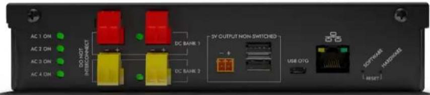
Squid has a total of nine LED Indicators:
• [4] AC Outlet. When illuminated, the corresponding AC outlet is on
• [2] DC Output. When illuminated, the corresponding DC output is on
• [2] Ethernet Connection and Activity
• [1] Surge Protection OK (on opposite side of pictured view)
4. Buttons
There are two recessed pushbuttons located to the right of the Ethernet RJ-45 jack. The Hardware Reset button is furthest from the RJ-45 jack, and the Software Reset button is closest.
4.1 Hardware Reset
The Hardware Reset button performs a hard reboot of the processor. This hard reboot will immediately switch controlled outlets off, removing power to connected equipment on all outputs except the 5V output.
4.2 Software Reset
The Software Reset button is a multi-functional control depending on length of press. If the button is held for greater than 10 seconds, the unit resets itself to factory defaults, and all custom configurations are erased. If the button is held for less than 10 seconds, the unit will perform a software reset that will not reset any data, or power cycle the connected equipment.
5. Web Server
Squid's internal web server provides a comprehensive portal for configuration, monitoring, and control.
5.1 Login
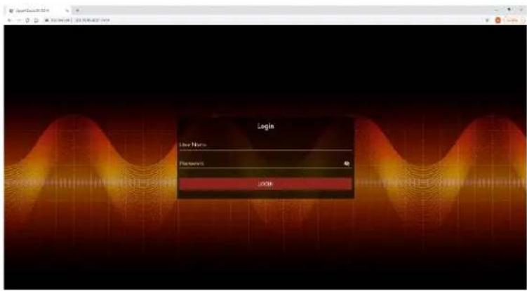
The Login page is the first page displayed when a web browser makes a connection to the Squid. Enter a valid user name and password in the "User Name" and "Password" fields, and press "Login" to log in.
5.2 Power Management
The Power Management page provides information and status for the whole unit and individual outlets, as well as basic control of outlets. The top right section of the page provides system status.
![ESPO SAGX Power Management - Default Squid Device [AC:06:57:00:20:02] Control Panel All Squids Control Panel Sagin 1 Sagin 2 Sagin 3 Sagin 4 Sagin 5 Sagin 6 Sagin 7 Sagin 8 Sagin 9 Sagin 10 Sagin 11 Sagin 12 Sagin 13 Sagin 14 Sagin 15 Sagin 16 Sagin 17 Sagin 18 Sagin 19 Sagin 20 Sagin 21 Sagin 22 Sagin 23 Sagin 24 Sagin 25 Sagin 26 Sagin 27 Sagin 28 Sagin 29 Sagin 30 Sagin 31 Sagin 32 Sagin 33 Sagin 34 Sagin 35 Sagin 36 Sagin 37 Sagin 38 Sagin 39 Sagin 40 Sagin 41 Sagin 42 Sagin 43 Sagin 44 Sagin 45 Sagin 46 Sagin 47 Sagin 48 Sagin 49 Sagin 50 Sagin 51 Sagin 52 Sagin 53 Sagin 54 Sagin 55 Sagin 56 Sagin 57 Sagin 58 Sagin 59 Sagin 60 Sagin 61 Sagin 62 Sagin 63 Sagin 64 Sagin 65 Sagin 66 Sagin 67 Sagin 68 Sagin 69 Sagin 70 Sagin 71 Sagin 72 Sagin 73 Sagin 74 Sagin 75 Sagin 76 Sagin 77 Sagin 78 Sagin 79 Sagin 80 Sagin 81 Sagin 82 Sagin 83 Sagin 84 Sagin 85 Sagin 86 Sagin 87 Sagin 88 Sagin 89 Sagin 90 Sagin 91 Sagin 92 Sagin 93 Sagin 94 Sagin 95 Sagin 96 Sagin 97 Sagin 98 Sagin 99 Sagin 100](/content/2026/05/911319/images/77ab53d2125421af663c41e640c63b3f74ac1276b8f66456aa04c058cdf69e01.jpg)
5.3 Reports
The Reports page displays data collected by Squid, and stored to its internal memory. The data is presented in two groups: Time Stamped Events and Historical Data.
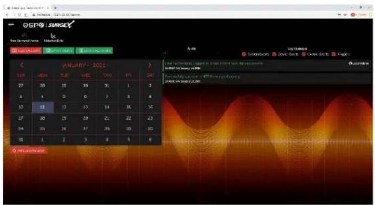
Time Stamped Events are recorded, with a date and time of occurrence, when a condition meets established criteria. Squid uses a Real Time Clock (RTC) synced to an Internet time server, and backed up by an internal battery. For the most accurate time stamps and to eliminate clock drift, we suggest verifying the NTP connection.
The types of events which may be recorded are:
- Triggers
- Surge Protection Failed
- Power Outage
- Network Events
- Outlet Changes
- Shutdown Events
- Firmware Upgrades
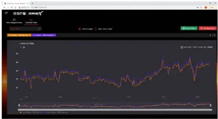
Historical Data is a record of measured electrical parameters, and may be adjusted to sample certain items at specific intervals. The available parameters are:
line
| Date | SPX Index Value | S&P 500 Index Value | S&P 500 Index Value | | ---------- | --------------- | ------------------- | ------------------- | | 2001 | ~1.5 | ~1.2 | ~0.8 | | 2002 | ~1.6 | ~1.3 | ~0.9 | | 2003 | ~1.4 | ~1.1 | ~0.7 | | 2004 | ~1.7 | ~1.4 | ~1.0 | | 2005 | ~1.5 | ~1.2 | ~0.8 | | 2006 | ~1.6 | ~1.3 | ~0.9 | | 2007 | ~1.4 | ~1.1 | ~0.7 | | 2008 | ~1.7 | ~1.5 | ~1.1 | | 2009 | ~1.5 | ~1.3 | ~0.9 | | 2010 | ~1.6 | ~1.4 | ~1.0 | | 2011 | ~1.4 | ~1.2 | ~0.8 | | 2012 | ~1.7 | ~1.5 | ~1.1 | | 2013 | ~1.5 | ~1.3 | ~0.9 | | 2014 | ~1.6 | ~1.4 | ~1.0 | | 2015 | ~1.4 | ~1.2 | ~0.8 | | 2016 | ~1.7 | ~1.5 | ~1.1 | | 2017 | ~1.5 | ~1.3 | ~0.9 | | 2018 | ~1.6 | ~1.4 | ~1.0 | | 2019 | ~1.4 | ~1.2 | ~0.8 | | 2020 | ~1.7 | ~1.5 | ~1.1 | | 2021 | ~1.5 | ~1.3 | ~0.9 | | 2022 | ~1.6 | ~1.4 | ~1.0 | | 2023 | ~1.4 | ~1.2 | ~0.8 || Historical Parameter | Description | |
| Voltage Max | Line - Neutral | The maximum measured RMS voltage between the conductors during the measurement period. |
| Neutral - Ground | ||
| Voltage Min | Line - Neutral | The minimum measured RMS voltage between the conductors during the measurement period. |
| Neutral - Ground | ||
| Voltage Average | Line - Neutral | The average measured RMS voltage between the conductors during the measurement period |
| Neutral - Ground | ||
| Voltage Peak Max | Line - Neutral | The maximum measured peak voltage between the conductors during the measurement period. |
| Neutral - Ground | ||
| Current Max | Total Device | The maximum measured RMS current during the measurement period. |
| Current Average | Total Device | The average measured RMS current during the measurement period. |
| Current Peak Max | Total Device | The maximum measured peak current during the measurement period. |
| Power Max | Total Device | The maximum measured average power during the measurement period. |
| Power Average | Total Device | The average measured average power during the measurement period. |
| Power Peak Max | Total Device | The maximum measured peak power during the measurement period. |
| Frequency Max | The maximum measured Line1-Line2 AC line frequency. | |
| Frequency Min | The minimum measured Line1-Line2 AC line frequency. | |
| Frequency Average | The average measured Line1-Line2 AC line frequency. | |
| Power Factor Mode | Total Device | The most commonly recorded power factor during the measurement period. |
| Crest Factor Max | Line Voltage | The maximum crest factor calculated during the measurement period. |
| Neutral - Ground Voltage | ||
| Current | ||
| Crest Factor Min | Line Voltage | The minimum crest factor calculated during the measurement period. |
| Neutral - Ground Voltage | ||
| Current | ||
| Energy Usage | Total Device | The accumulated energy consumed by connected equipment during the measurement period. |
5.4 Setup
Complete setup and configuration of Squid is provided via 6 Setup web pages. Each setup page is described in the following sections. Each setup page has a save button at the bottom of the page, be sure to press the save button at the bottom of the page to keep the configuration changes. A green success message will temporarily appear in the top right of the page when then settings are saved properly.
| Setup | |
| Setup Page | Description |
| Device | Configure basic device parameters |
| Device Configuration | Configure settings for visual feedback and power up procedure |
| Outlet Configuration | Configure controllable outlet settings |
| Outlet Group Configuration | Create, edit, or delete outlet groups |
| Date/Time Settings | Configure NTP server, or set manual time |
| Network | Configure network settings, including the network adapter and time keeping |
| Network Advanced | Configure advanced monitoring and security settings |
| SNMP | Configure SNMP connection and communication settings |
| 802.1X Settings | Configure authentication settings and/or view connection logs. |
| LDAP Client Settings | Configure LDAP authentication options, and test connection |
| Users | Configure and modify user accounts |
| Triggers | Create and modify Triggers |
| Threshold with Samples | Configure triggers based on measurements |
| AutoPing | Configure triggers based on pinging IP addresses |
| Schedule | Configure triggers based on time |
| Sequences | Create and modify custom Sequences |
5.4.1 Device Setup
The Device Setup page allows for the specification of basic device parameters.
5.4.1.1 Device Configuration
The Device Configuration tab allows for the specification of visual feedback, and device initialization.
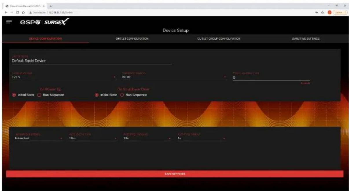
| Device Configuration | |
| Item | Description |
| Device Name | Specifies the name label to be associated with this Squid. |
| Nominal Voltage | Specifies the expected voltage on the input receptacle. This selection does NOT change any settings for over/under voltage shutoff. This is only for visual coloring on gauges. |
| Nominal Frequency | Specifies the expected frequency on the input receptacle. This selection does NOT change any settings for triggers. This is only for visual coloring on gauges. |
| Power Up Delay Time | Specifies the amount of time in seconds by which to stagger the manual turning on of multiple outlets when applying the initial state. |
| On Power Up | Specify whether to set outlets to Initial States or run a predefined Sequence when Squid powers up, or the Hard Reset button is pushed. |
| On Shutdown Clear | Specify whether to set outlets to Initial States or run a predefined Sequence when a Shutdown State clears. |
| Temperature Display | Specifies whether to display temperature in degrees Fahrenheit or Celsius. |
| Auto Logout | Specifies the web security timeout in minutes. |
| Auto Ping Frequency | Specifies how frequent the Squid will send pings to an IP Address or Hostname in an autoping trigger. |
| Auto Ping Timeout | Specifies the amount of time the Squid will wait for a ping response before calling the attempt a failure. |
5.4.1.2 Outlet Configuration
The Outlet Configuration tab allows for the specification of unique names and reboot times per outlet. The configuration for initial state per outlet is also here, if this option is selected in the Device Configuration tab for either On Power Up or On Shutdown Clear.
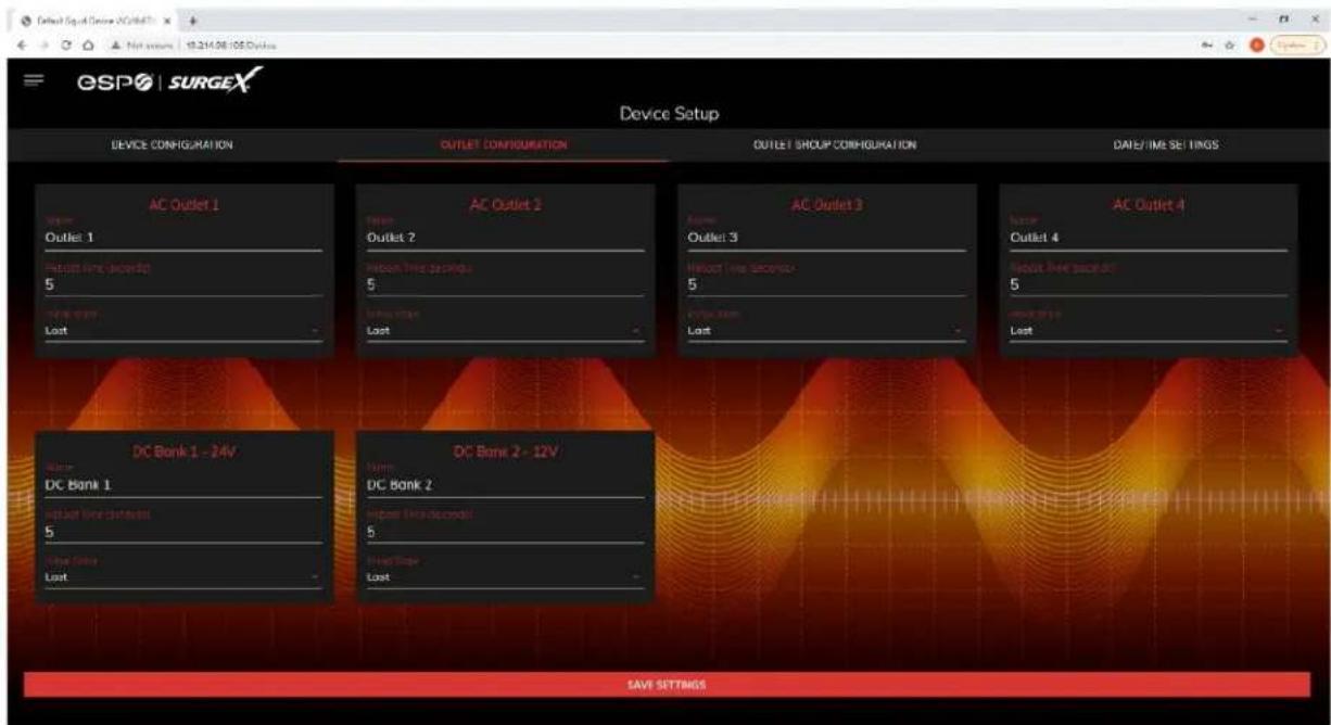
| Outlet Configuration | |
| Item | Description |
| Outlet Description | A fixed short phrase that references a physical feature. |
| Outlet Name | Specifies the name label to be associated with this Outlet |
| Reboot Time | Number of seconds that the device will wait in between turning an outlet off, and turning the outlet back on during a reboot command. |
| Initial State | The state that an outlet will assume during start up or after a shutdown clears, if the initial state setting is selected in the Device Configuration tab. Options are as follows:Always On Regardless of other settings, this outlet will always be on. Ignores Shutdown state and deselecting Initial State in the Device Configuration tab. Outlet ignores user commands to reboot or power off. The only thing that will kill power with this selected is a hard reboot, or power outage.Always Off The opposite of Always On, this setting will never allow an outlet to pass power.On The outlet will start in an On state.Off The outlet will start in an Off state.Last The outlet will assume the last state it was in. (Factory Default)Reboot Only The outlet will act similar to the On state, but will ignore user commands to power off. This outlet will only respond to reboot commands. Useful for network appliances that may need to be rebooted, but otherwise want to be on all the time. Using this setting, the outlet will still turn off during Shutdown state. |
5.4.1.3 Outlet Group Configuration
The Outlet Group Configuration tab allows for the specification of visual feedback, and device initialization.
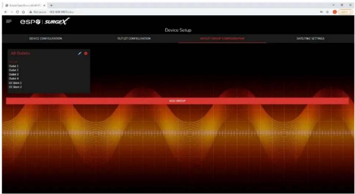
| Outlet Group Configuration | |
| Item | Description |
| Group Name | Specifies the name label to be associated with this Squid. |
| Member Name | Specifies the expected voltage on the input receptacle. This selection does NOT change any settings for over/under voltage shutoff. This is only for visual coloring on gauges. |
5.4.1.4 Date/Time Settings
The Date/Time Settings tab allows for the specification of visual feedback, and device initialization.
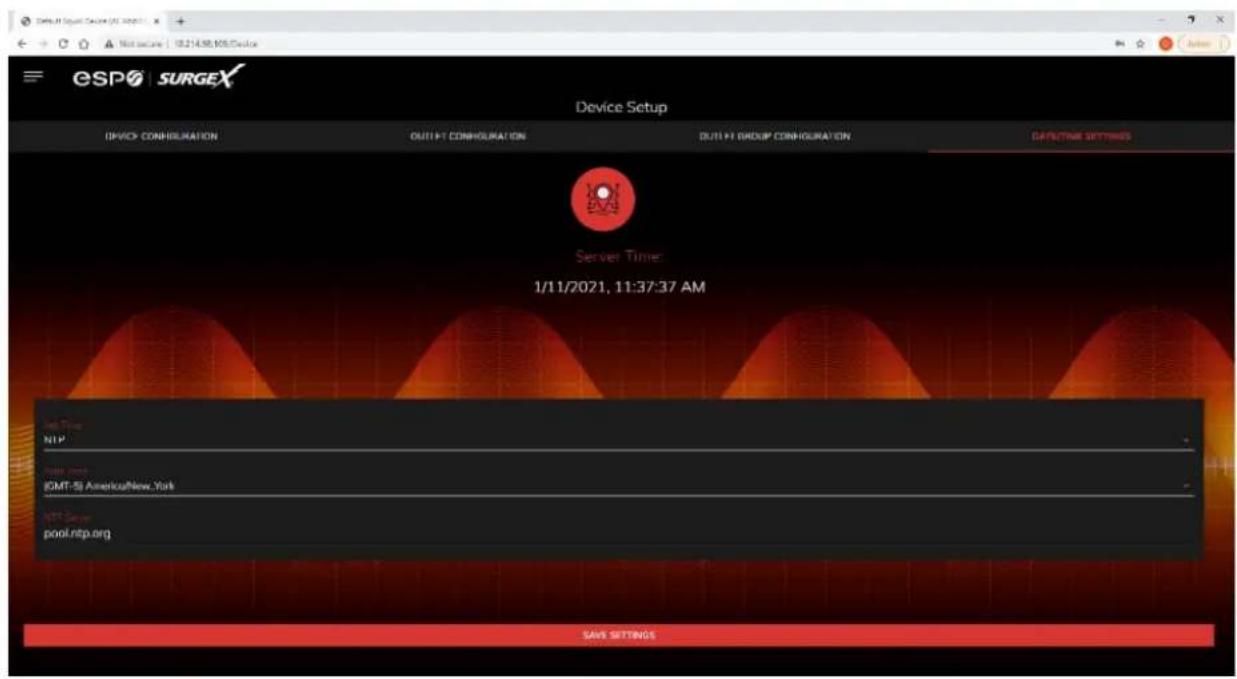
| Date/Time Configuration | |
| Item | Description |
| Server Time | Returns the device's internal time based on the local time zone. |
| Set Time | Specifies the method for setting the time in the Squid unit. Options for this setting are NTP or manual. NTP will use the NTP Server option to automatically sync the device time every day. |
| Time Zone | Specifies the desired time zone adjustment for the Squid device. |
| NTP Server | Specifies the hostname or IP address of the NTP server to use for time synchronization. |
5.4.2 Network Setup
The Network Setup page allows for the specification of network settings, including the network interface and time server.
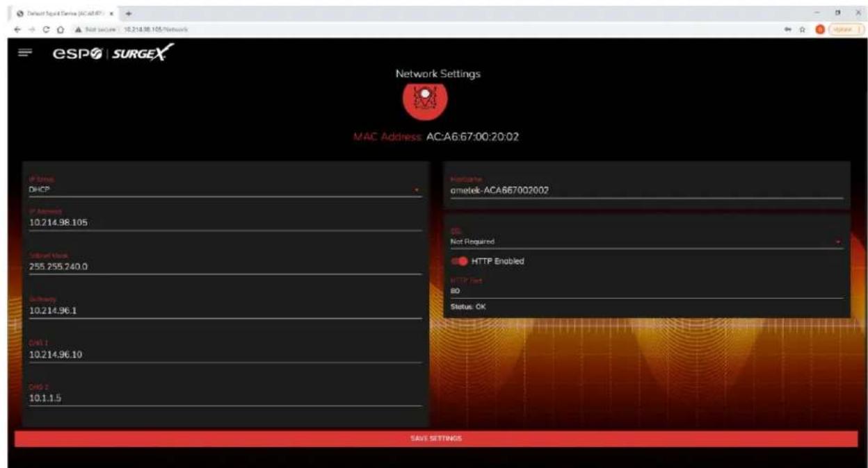
| Network Configuration | |
| Item | Description |
| IP Setup | Specifies if the device will have a static IP Address, or will dynamically be assigned network settings through DHCP. |
| IP Address | Current IP Address of the network interface on the RJ45 Ethernet port. |
| Subnet Mask | Current Subnet Mask of the network interface on the RJ45 Ethernet port. |
| Gateway | Current Gateway of the network interface on the RJ45 Ethernet port. |
| DNS 1 | Current DNS1 of the network interface on the RJ45 Ethernet port. |
| DNS 2 | Current DNS2 of the network interface on the RJ45 Ethernet port. |
| Hostname | A configurable unique name to be used to access the device instead of an IP Address. |
| SSL | Specifies whether the web server will be SSL encrypted (HTTPS) or not (HTTP). The default certificate is self-signed, and will require the user continue through a safety notification if a custom signed certificate is not uploaded to the device. |
| HTTP Enabled | Specifies if the web server is enabled or disabled. NOTE: If disabling the web server, the web interface and REST API will be disabled, only limited functionality over SNMP will remain if enabled. |
| HTTP Port | Port number to use for the web server. |
5.4.3 Network Advanced Setup
The Network Advanced Setup page allows for the specification of more advanced network security and monitoring options.
5.4.3.1 SNMP
The SNMP tab allows for the specification of parameters for the SNMP agent, supporting V1 through V3.
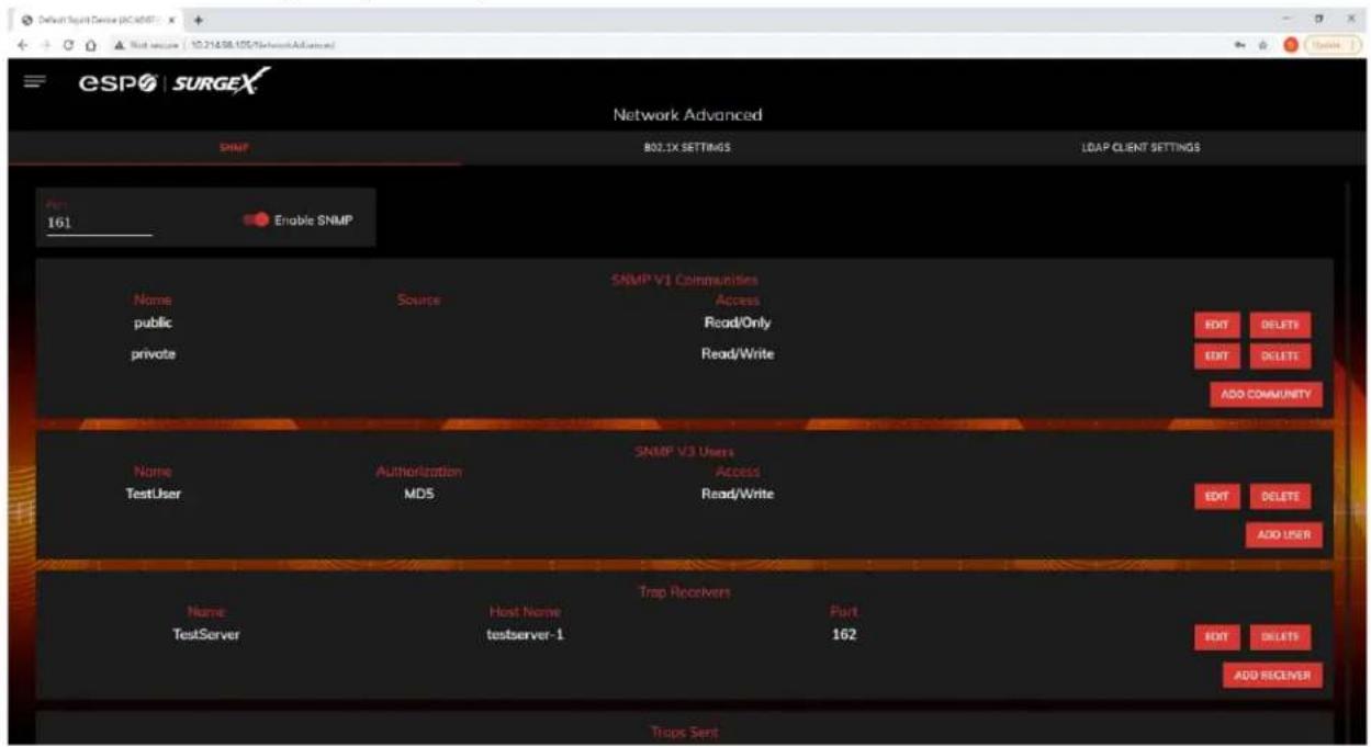
| SNMP Setup | |
| Item | Description |
| Enable SNMP | Specifies whether or not to enable the SNMP agent. |
| Port | Specifies the port number for the SNMP agent. 161 is the standard SNMP port. |
| SNMP V1 Communities | Is a table of all SNMP communities, supporting SNMP V1 at a minimum. |
| Name | Specifies the Community name for read and/or write access. |
| Source | Specifies an unrequired whitelist. If requests are not to be filtered by hostname or IP Address, this field can be left blank. |
| Access | Specifies the type of access allowed by the community. |
| SNMP V3 Users | Is a table of Users specifically for SNMP V3 authorization. Users here will not apply to the REST API, and REST API users will not be able to authenticate via SNMP V3 without redefining their credentials here. SNMP credentials cannot be authenticated using the LDAP Client. |
| Name | The name or username for authorization. |
| Authorization | Type of encryption used per user. Options are DES or MD5. |
| Access | Type of access per user. Options are Read Only or Read/Write. |
| Passphrase | Passphrase or password for the user. |
| Trap Receivers | Is a table of all the destinations for SNMP traps. |
| Name | The name of the community for traps. |
| Host Name | The hostname or IP address of the SNMP Manager that is going to receive traps. |
| Port | The port number that the SNMP Manager is listening for traps on. |
| Traps Sent | Specifies which specific traps are to be sent. Triggers send traps for Triggering and Clearing. Manual Control sends traps for outlet state changes, and Authentication sends traps for failed authentication attempts. |
5.4.3.2 802.1X Settings
The 802.1X Settings tab allows for the specification of 802.1X authentication and debugging of errors as they may arise.
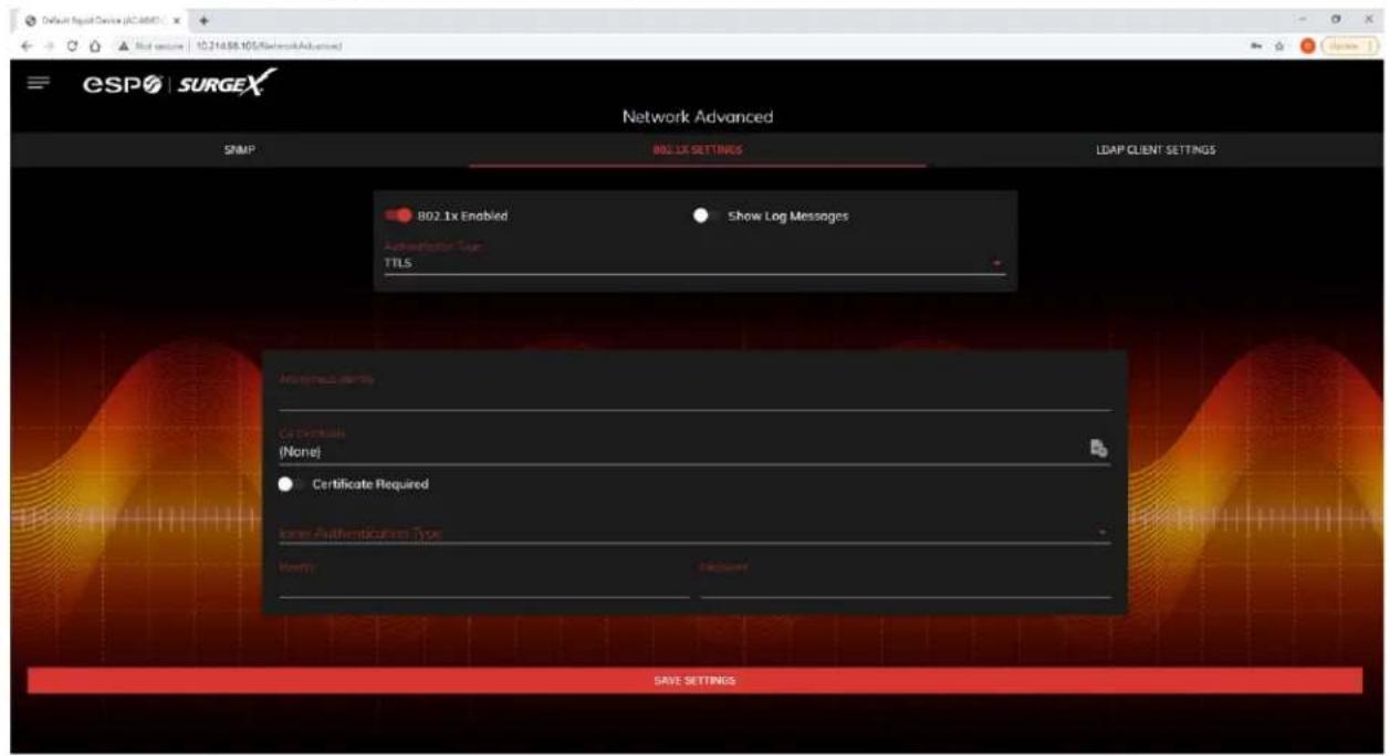
| 802.1X Settings Setup | |
| Item | Description |
| 802.1x Enabled | Enables the 802.1x authentication client. This does not require the user to have a unique password for Squid. Network login credentials can be used. |
| Show Log Messages | Opens and hides a table with date/time coded 802.1x related messages for debugging an authentication failure. |
| Authentication Type | Specify the authentication method used during the 802.1x EAP negotiation. Different authentication options and settings will be displayed based on the selected Authentication Type. |
5.4.3.3 LDAP Client Settings
The LDAP Client Settings tab allows for the specification of the LDAP Authentication server and authentication method, and a test interface to test the server setup.
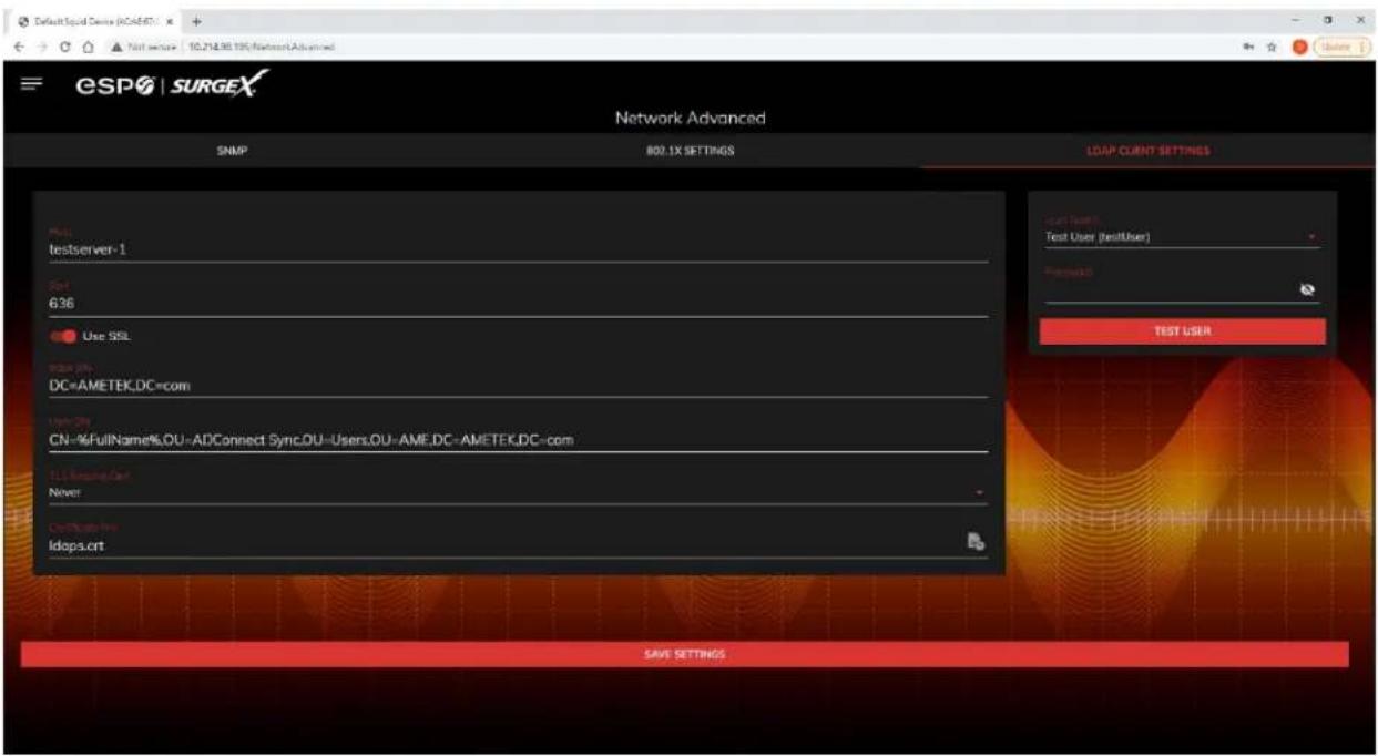
| LDAP Client Settings Setup | |
| Item | Description |
| Host | The hostname or IP address of the LDAP server |
| Port | The port number of the Directory System Agent running on the LDAP server. The default port number for unsecured LDAP is 389. The default port number for LDAPS or LDAP over SSL is 636. |
| Use SSL | A switch that will enable or disable SSL when attempting to connect to the LDAP server. This is a separate option than the port number, in the case that a site is using a nonstandard port for authentication, but still wants the ability to specify encryption. We always suggest using encryption when using LDAP. |
| Base DN | The base point in the directory tree where the user distinguished name search will begin. |
| User DN | The distinguished name of a user that will be used to authenticate. Multiple users are supported by using macros. For example in the above image, the username testUser attempts to log in, and the User DN pulls the name “Test User” from the user’s definition for use in the authentication to replace the string %FullName%. |
| TLS Require Cert | This specifies how to handle server certificates during TLS negotiations. Never: the client never asks the server for a certificate. Allow: the client will ask for a certificate; if none is provided the session proceeds normally. If a certificate is provided but the client is unable to verify it, the certificate is ignored and the session proceeds normally, as if no certificate had been provided. Try: the certificate is requested, and if none is provided, the session proceeds normally. If a certificate is provided and it cannot be verified, the session is immediately terminated. Demand: the certificate is requested and a valid certificate must be provided, otherwise the session is immediately terminated. |
| Certificate File | This is the certificate that will be sent to the LDAP Server when/if requested. |
| User Name | The information for a user that is defined in the Users page. The first part (name), is accessible by the %FullName% macro, and the second part (username) is accessible with the %UserName% macro. |
| Password | The password for the given user to test the LDAP server configuration. |
| Test User | A button to send an authentication request using the given settings for the user and password above. NOTE: Settings should be saved using the “Save Settings” button at the bottom of the page before testing a configuration change. |
5.4.4 Triggers Setup
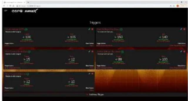
The Triggers Setup page allows for the modification of Triggers. Triggers define event logging parameters, and allow configuration to automatically control and protect connected equipment.
Triggers are categorized into three types, AutoPing, Threshold with Samples, and Schedule, but all have the same possible actions. Actions can either be on the onset (Trigger/Alarm Actions) or offset (Clear Actions) of a trigger. All Triggers are logged, along with the associated actions.
| Trigger Types | |
| Item | Description |
| Threshold with Samples | Uses measurements over an allotted time to take an action. This trigger type is configurable to act very quickly or very slowly depending on environmental/system needs. |
| AutoPing | Issues a ping function on a periodic basis to determine if an IP asset is accessible. |
| Schedule | Uses the device time to issue a one time or periodic command. We suggest ensuring the NTP server is updating correctly to use the schedule trigger. |
| Action Types | |
| Item | Description |
| None | Do not take any action, only log the event. This is useful as a Clear Action when an action should persist, or for both Alarm and Clear actions when just logging the event is desired. |
| Power On | Power on a specific outlet if the outlet configuration allows it. |
| Power Off | Power off a specific outlet if the outlet configuration allows it. |
| Reboot | Reboot a specific outlet if the outlet configuration allows it. If an outlet is already off when this command is issued, the outlet will simply turn on after the outlet specific reboot delay time. |
| Run Sequence | Run a specific sequence. |
| Enter Shutdown State | Put the device into a shutdown state. This state turns off all outlets (unless they are configured for always on). The only way to clear a shutdown state, is another trigger, a button on the web interface, or a REST API command. |
| Clear Shutdown State | Clear the device's shutdown state. Clearing the device's shutdown state will cause the outlets to follow the logic defined by the On Shutdown Clear setting. |
5.4.4.1 Threshold with Samples
The Threshold with Samples trigger uses a number of measurements to decide when to take action. The trigger is able to be configured to act quickly, or slowly, depending on the number of measurement samples used. A new sample is available every 50ms, with the minimum samples being used for a trigger being 1 sample, and the maximum being 20 samples.
Threshold with Samples triggers are evaluated every time a new sample is available. Based on the below "New Trigger" example below, the trigger will alarm or turn on after 5 of any consecutive 10 samples are above 140V.
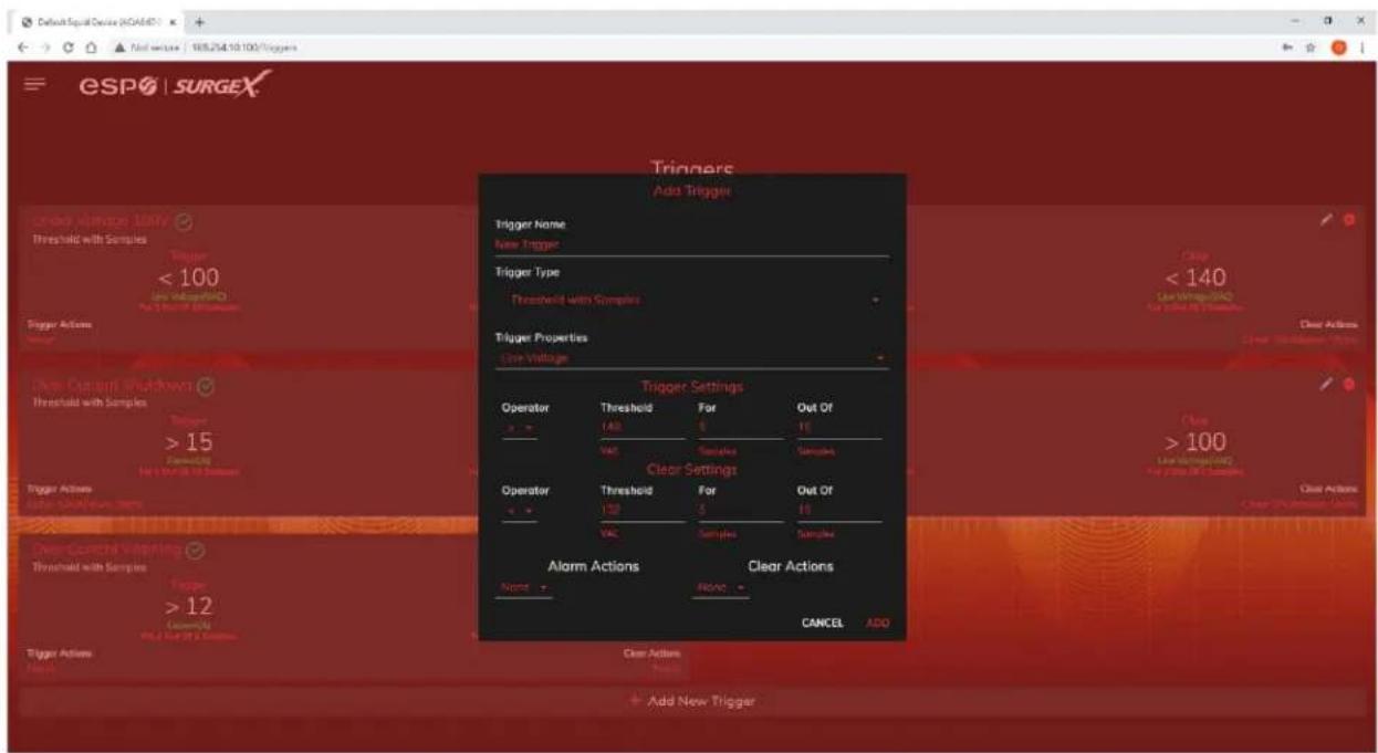
| Item | Options | Description |
| Trigger Properties | Line Voltage | Uses the Line to Neutral voltage measurement. Measurement accuracy is between 40 VAC and 300 VAC. |
| N-G Voltage | Uses the Neutral to Ground voltage measurement. Measurement accuracy is between 0.6 VAC to 300 VAC. | |
| Current | Uses the current measurement, which includes total product current. Measurement accuracy is between 0.1 A and 30 A. | |
| Temperature | Uses the internal temperature measurement. This should not be treated as an ambient temperature and will vary drastically based on loading. | |
| Frequency | Uses the frequency measurement. Measurement accuracy is between 45 Hz and 65 Hz. | |
| Average Power | Uses the average power measurement. Measurement accuracy is between 4 W and 7200W. | |
| Crest Factor | Uses the Line to Neutral Voltage Crest Factor. | |
| Power Factor | Uses the Power Factor. | |
| Operator | > | Requires “For” number of measurements to be greater than the threshold. |
| < | Requires “For” number of measurements to be less than the threshold. | |
| = | Requires “For” number of measurements to be exactly equal to the threshold. | |
| Threshold | Numerical Range | Is the number to be evaluated against all measurements to either trigger or clear the Trigger. |
| For | 1 – 20 | The number of measurements out of the given number of samples being evaluated that must meet the criteria to trigger or clear the Trigger. |
| Out Of | 1 – 20 | The number of consecutive measurements to be evaluated to trigger or clear the Trigger. |
5.4.4.2 AutoPing
The AutoPing trigger uses a ping command on a periodic basis defined in the device settings to test if a specific IP address will respond. This trigger type is useful if there is a problematic piece of equipment that becomes unresponsive, or if internet connectivity is inconsistent.
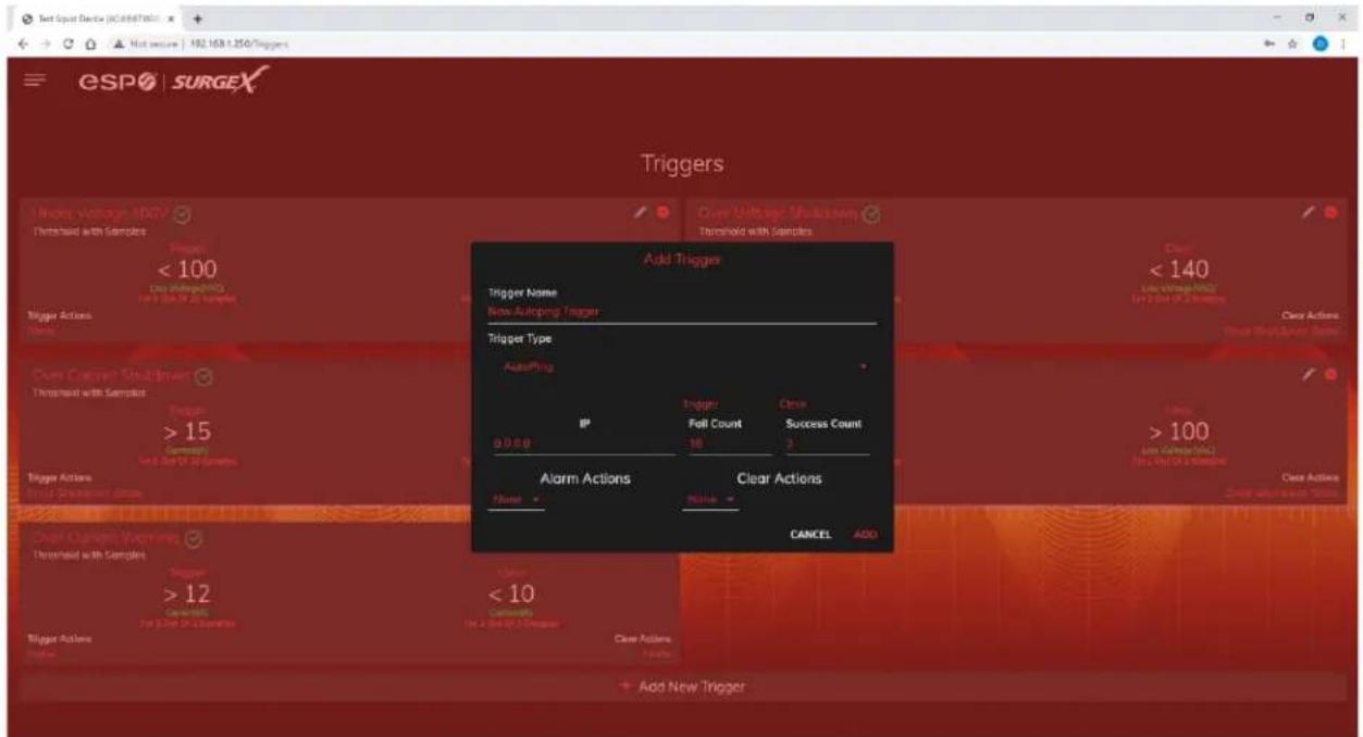
| Item | Description |
| IP | IP address to be pinged at the period set on the device configuration page. |
| Fail Count | Number of consecutive failed ping responses needed to trigger the AutoPing trigger. |
| Success Count | Number of consecutive successful ping responses needed to clear the AutoPing trigger. |
5.4.4.3 Schedule
The Schedule trigger uses the internal time of the Squid to easily configure single and recurring events based on time. Only Alarm Actions are used for this trigger.
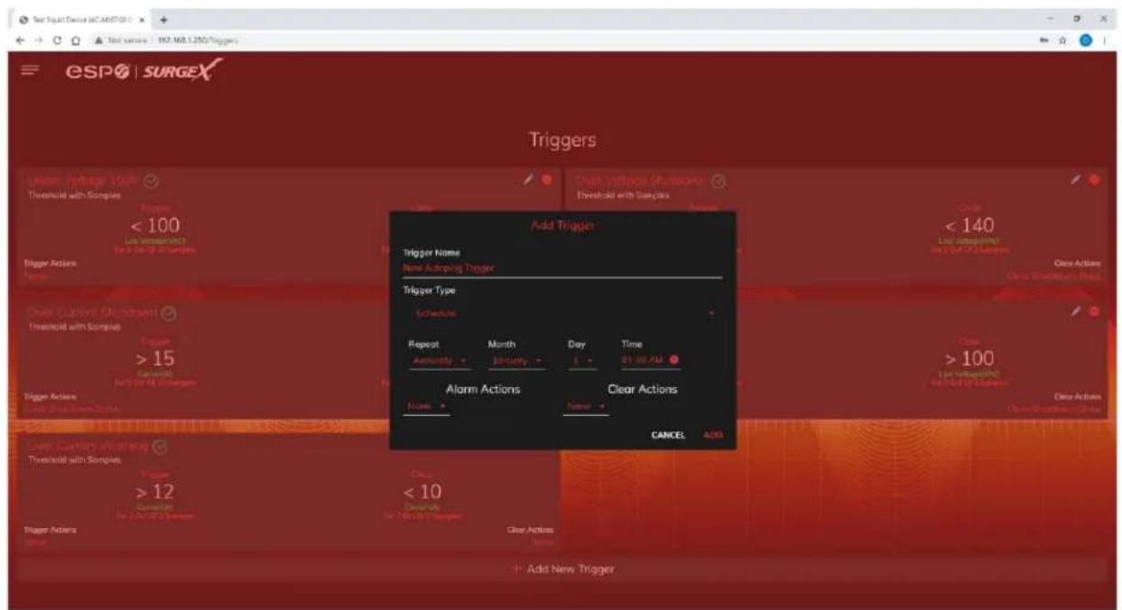
| Item | Options | Description |
| Repeat | Never | The trigger will only fire when the time reaches the time shown in the configuration the next time. |
| One Time | The trigger will only fire once, on the specific date and time shown in the configuration. | |
| Daily | The trigger will fire every day at the given time. | |
| Weekly | The trigger will fire every week on the selected day(s) at the given time. | |
| Monthly | The trigger will fire every month on the given day of the month at the given time. | |
| Annually | The trigger will fire every year on the given day of the given month at the given time. | |
| Date | Date Picker | A specific date to be used in the One Time trigger. |
| Days | Sunday - Saturday | A set of day(s) that can be selected for use in the Weekly trigger. |
| Day | 1 - 31 | A day of the month to be used in the Monthly or Annually trigger. |
| Month | January - December | A month of the year to be used in the Annually trigger. |
| Time | 12:00 AM – 11:59 PM | A given time to be used in all scheduling triggers. |
5.4.5 Users Setup
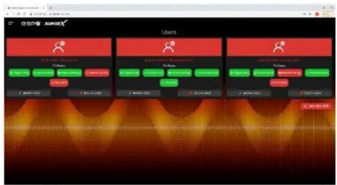
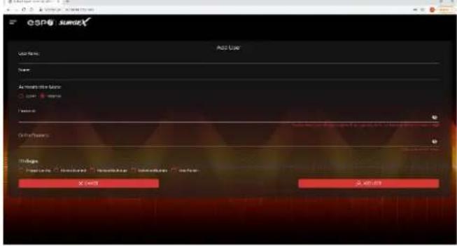
The Users Setup page allows for the creation, deletion, and editing of user accounts. Each user will have a unique name, user name, authentication mode, and may be assigned access to specific features.
LDAP and Internal authentication modes are supported.
The following privileges may be assigned or revoked as necessary:
- Trigger Config
- Device Control
- Network Settings
- Software Update
- User Administration
5.4.6 Sequences Setup
The Sequences Setup page allows for the creation and modification of sequences. A sequence is a set of actions to be taken in a specific order, and with a specified delay time between each step. Using sequences avoids manually performing each action, or turning each outlet on or off, individually.
A sequence, as defined for this product, is purely a one-way sequence. That is, you do not use the same sequence to turn outlets on as you use to turn the same outlets off in reverse order. One sequence must be created for the turn-on function, and then a second sequence must be created for the turn-off function.
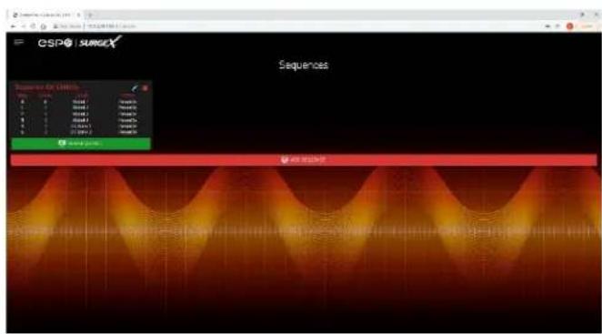
To create a new sequence, press the "Add Sequence" button. The new sequence must be given a unique name. This name should clearly indicate what the sequence will do, such as "All On", "All Off" or "Stage Equipment On".
To run a sequence to test it, press "Run Sequence". To edit an existing sequence, press the pencil icon. To delete a sequence, press the minus "-" icon.
After a sequence has been saved, it will be available at the Sequences page, and when creating or editing a trigger when run sequence is selected as an action.
*Time delay is specified from the previous sequence item, not from the initial starting point. For example, creating a sequence with "Step 1, 1 second, Outlet 1, On" and "Step 2, 1 second, Outlet
2, On" will turn on Outlet 1 after 1 second, and Outlet 2 on 1 second after
Outlet 1 has turned on. This sequence will not turn on both Outlets 1 and 2 at the same time.
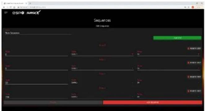
Sequence Actions:
• None (useful for additional time delays)
- State Change
○ On, Off, or Reboot.
5.5 Utilities
Squid contains several utilities to ease the configuration and deployment that may be performed on a per unit basis through several web pages.
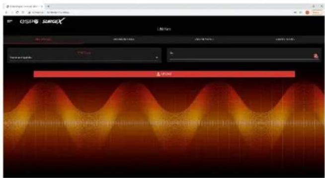
5.5.1 File Upload
Squid allows for a variety of files to be uploaded. This is also the method for upgrading the firmware. Current firmware versions can be obtained from the SurgeX website. Squid will not automatically contact SurgeX servers for new firmware. Other files that can be uploaded include a variety of certificates and configurations. By default, Squid ships with a self-signed HTTPS certificate if HTTPS is enabled. A different certificate can be uploaded for use by the HTTPS server by selecting "HTTPS SSL Certificate" under the File Type drop down.
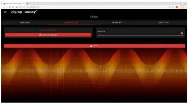
The current configuration may be saved to a file and downloaded for archival. Previously stored configurations may be applied to other units to easily mass configure a larger deployment. IP Settings will not be saved in the Backup Configuration.
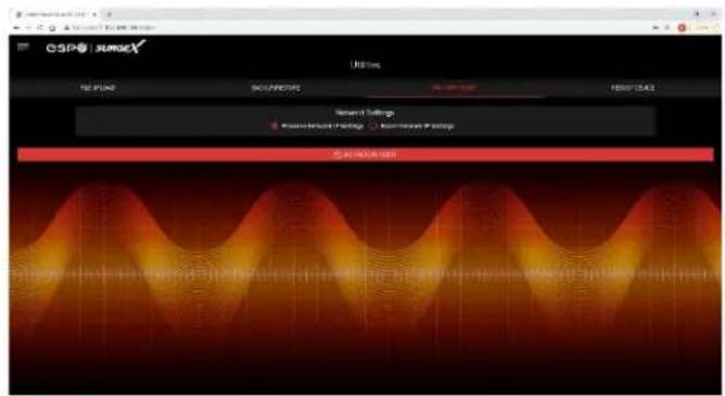
5.5.3 Factory Reset
Factory default settings may be applied through the web interface.
- Option to keep or reset network IP settings.
- Web Server settings will be reset. A custom port number will be reset to 80, and SSL will be disabled by default.
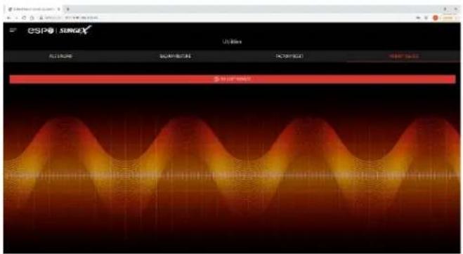
5.5.4 Soft Reboot
Adds the ability to reboot the Squid processor. A soft reboot will not change the outlet state or disconnect power from connected equipment. This request will add a message in the event log "Rebooting Adapter Due to User Request".
6. Security
Squid has been designed with security as a priority. All ports and features may be changed or disabled.
6.1 Authentication
Squid supports basic and secure authentication for users and network connections.
6.1.1 802.1X
802.1X network authentication may be enabled for networks requiring supplicant authentication.
6.1.2 SSO (Single Sign-On)
Squid users may be configured to use either Internal or SSO (Single Sign-On) authentication. Internal authentication uses basic usernames and passwords assigned by the administrator on a per-unit basis. SSO authentication uses LDAP (Lightweight Directory Access Protocol) to authorize users, and determine their level of privileges, using Microsoft® Active Directory. While it is possible to use LDAP to authorize users without SSL encryption, we suggest only configuring the connection to the authentication server using SSL encryption to plain text network traffic.
6.2 Interfaces
6.2.1 Network Interface
- Web Server: It is possible to enable and disable the internal web server, change the security from none (HTTP) to TLS 1.2 (HTTPS), as well as change its port. These settings also apply to the REST API.
• SNMP: Squid supports SNMP V3 for secure communications, with the ability to enable and disable.
6.3 Statement of Volatility
SurgeX Squid Series (SX-DC-8-12-X, SX-DC-8-24-X, SX-DC-8-1224-X)
Statement of Volatility
Date Issued: July 23, 2021
The chart below shows the corresponding memory types for the SurgeX Squid series.
MCU
| Model | Memory Size (Bytes) | Memory Type | Volatility | User Data |
| SX-DC-8-12-X | 96 KB | ROM | Non-Volatile | No |
| SX-DC-8-24-X | 512 KB | RAM | Volatile | No |
Memory ICs
| Model | Memory Size (Bytes) | Memory Type | Volatility | User Data |
| SX-DC-8-12-X | 128 Mb | Flash | Non-Volatile | Yes |
| SX-DC-8-24-X | 256 Mb | SDRAM | Volatile | Yes |
| SX-DC-8-1224-X | 64 Bytes | SRAM | Volatile | No |
| 128 Bytes | EEPROM | Non-Volatile | No |
7. Application Programming Interfaces (APIs)
Squid is designed for flexible communication and integration with diverse control and monitoring platforms.
7.1 HTTP/HTTPS REST
Squid includes an extensive HTTP API (HTTPS when security is enabled) in JSON format. Full protocol details are available at http://www.ametekesp.com.
7.2 SNMP
SNMP V3 communications are intended to provide essential items for management. Read, Write, Table, and Trap objects will be included. Full protocol details, and the SNMP MIB, are available at http://www.ametekesp.com.
8. Ordering Information
8.1 Part Number Scheme
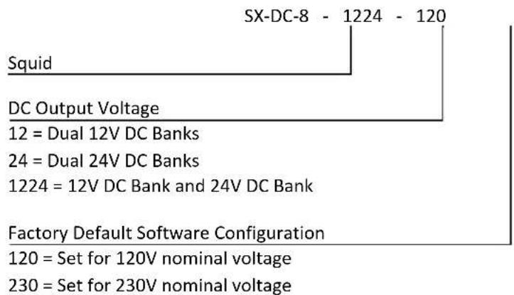
- Specifications
| Parameter | Specification | |||||
| AC Load RatingMaximum Full Load | North America | 12 Amps at 120 Volts | ||||
| Rest of World | 10 Amps at 240 Volts | |||||
| DC Load RatingMaximum Full Load | DC Output 1Rating | DC Output 2Rating | Combined DC1 +DC2 Rating | 5V Output Rating | ||
| SX-DC-8-12-X | 5A @ 12V | 5A @ 12V | 10A @ 12V | 3A @ 5V | ||
| SX-DC-8-24-X | 2.5A @ 24V | 2.5A @ 24V | 5A @ 24V | 3A @ 5V | ||
| SX-DC-8-1224-X | 2.5A @ 24V | 5A @ 12V | NA | 3A @ 5V | ||
| Power Requirement (no load) | 15 Watts | |||||
| DC Efficiency | 90% Typical | |||||
| Audible Noise at 1m | 35 dBA Typical | |||||
| Heat Generation | 185 BTU/h Max | |||||
| EMI/RFI Filter | Normal mode (50Ω load) | >30 dB 80 kHz – 50 MHz | ||||
| Common Mode (50Ω load) | >20 dB 160 kHz – 27.5 MHz>30 dB 310 kHz – 17.6 MHz | |||||
| Under-Voltage Auto Shutdown | Adjustable from 0V to 300V, or disabled. | |||||
| Over-Voltage Auto Shutdown | Adjustable from 125V to 300V, or disabled. | |||||
| Over-Current Auto Shutdown | Adjustable from 0.1A to 20A, or disabled. | |||||
| Measurement Accuracy | Voltage | ±2% Typical Product Accuracy | ||||
| Current | ±2% Typical Product Accuracy | |||||
| Power | ±2% Typical Product Accuracy | |||||
| Energy | ±2% Typical Product Accuracy | |||||
| Timestamp Accuracy | ±1% Typical Product Accuracy | |||||
| Network Port | 10/100 Ethernet connection on Female RJ-45, Auto Negotiating with10/100 network connections with Link and Activity LEDsUSB RNDIS Device on micro AB | |||||
| Dimensions | 1.75"D x 10"L x 8.25"H | |||||
| Weight | SX-DC-8-12-X, SX-DC-8-24-X | 5 lb. | ||||
| SX-DC-8-1224-X | 5.5 lb. | |||||
| Temperature Range: | 100% Load | |||||
| SX-DC-8-12-X | 5C to 39C | |||||
| SX-DC-8-24-X | 5C to 47C | |||||
| SX-DC-8-1224-X | 5C to 42C | |||||
| Humidity Range | 0% to 95% R.H. Non-condensing | |||||
| Agency Listings | UL/CUL/CB 62368 | |||||
- Networked Power Conditioning and Energy Management AC/DC PDU
- User Manual
- AMETEK®
- POWER QUALITY SOLUTIONS
- Table of Contents
- Introduction
- Installation
- AC Power
- DC Power
- Ethernet
- USB OTG
- LED Indicators
- Buttons
- Hardware Reset
- Software Reset
- Web Server
- Login
- Power Management
- Reports
- Setup
- Device Setup
- Device Configuration
- Outlet Configuration
- Outlet Group Configuration
- Date/Time Settings
- Network Setup
- Network Advanced Setup
- SNMP
- 802.1X Settings
- LDAP Client Settings
- Triggers Setup
- Threshold with Samples
- AutoPing
- Schedule
- Users Setup
- Sequences Setup
- Utilities
- File Upload
- Factory Reset
- Soft Reboot
- Security
- Authentication
- 802.1X
- SSO (Single Sign-On)
- Interfaces
- Network Interface
- Statement of Volatility
- Application Programming Interfaces (APIs)
- HTTP/HTTPS REST
- SNMP
- Ordering Information
- Part Number Scheme
Brand : SurgeX
Model : Squid SX-DC-8-24-120
Category : Uncategorized