SX1115RT - Uncategorized SurgeX - Free user manual and instructions
Find the device manual for free SX1115RT SurgeX in PDF.


| Product Type | Rack-Mount Surge Protector / Power Conditioner |
| Rack Size | 19-inch, 1U |
| Number of Outlets | 9 (6 switched, 2 always on, 1 front courtesy) |
| Input Voltage | 120 V AC |
| Maximum Load (Total) | 15 A |
| Outlet Rating (Each) | 15 A |
| Surge Protection | Internal surge protection circuitry with self-test |
| Over/Under Voltage Protection | Turns off when voltage below 90 V or above 145 V |
| Inrush Current Elimination (ICE) | Built-in ICE circuit to absorb inrush energy on startup |
| Remote Control Input | Contact closure or applied DC voltage (5-30 V) via Phoenix terminal block |
| Auxiliary Relay Output | Form A relay, 1 A at 30 V DC, for cascading or feedback |
| Remote LED Output | 10 mA output for external LED (requires series resistor) |
| Indicator Lights | Power (red), Over/Voltage (orange), Self-Test (green), Remote (yellow) |
| Mounting | 19-inch equipment rack, 1U, horizontal |
| Safety | Do not cycle power rapidly under heavy load; wait 1 minute between turn-ons |
| Weight (Approx) | 5 lb (2.3 kg) |
| Compliance | Designed for 120 V, 20 A circuit (SX1115RT 15 A max) |
Frequently Asked Questions - SX1115RT SurgeX
User questions about SX1115RT SurgeX
0 question about this device. Answer the ones you know or ask your own.
Ask a new question about this device
Download the instructions for your Uncategorized in PDF format for free! Find your manual SX1115RT - SurgeX and take your electronic device back in hand. On this page are published all the documents necessary for the use of your device. SX1115RT by SurgeX.
USER MANUAL SX1115RT SurgeX
Installation Instructions
SX1115RT and SX1120RT
Mounting
The SurgeX SX1115/1120RT are designed to be installed in a 19 inch equipment rack and require one unit (1-U) of rack space. Remove the product from its packaging and slide it into place in the rack being careful to feed the power cord into the rack first and guide it so that it does not get caught or jammed as the product is installed.
120 Volt Connections
Connect power to the unit by plugging the cord into a 120V ac receptacle. The SX1120RT must be plugged into a 20 amp receptacle. If a 120V, 20 amp receptacle is not available, you will need to have one installed by a licensed electrical contractor.
The SX1115/1120RT have a total of 9 receptacles: six switched, two always on and a front panel courtesy outlet. Each receptacle is rated for a maximum load of 15 amps, but the total load must not exceed 15 amps for the SX1115RT and 20 amps for the SX1120RT. Plug the equipment cords into the always-on and switched receptacles as needed to power the equipment.
The always-on and courtesy receptacles provide power as long as power is supplied to the SurgeX and the AC voltage is within normal limits. The six switched outlets provide power only when the front panel switch is on and the remote control input is also activated.
Indicator Lights
The SX1115-RT and SX1120-RT have four indicator lights on the front panel. The red Power light indicates that the power switch is turned on, power is applied to the unit and the AC voltage is within normal limits. The orange Over/Under Voltage Protection light indicates that the AC voltage is below 90 volts or above 145 volts. The green Self-Test light indicates that power is applied to the unit and the internal surge protection circuitry is fully functional. The yellow Remote light indicates that the remote control is active and the rear switched receptacles are on.
CAUTION: Do not repeatedly turn an SX1115RT or an SX1120RT off—on—off—on with a heavy load connected. The ICE™ circuitry absorbs the inrush energy each time the unit is turned on and may overheat if this is done too many times in a short period of time. Wait one minute between repeated turn-ons.
Remote Control
Remote control connections are wired to the green 7-pin plug-in Phoenix terminal block on the rear of the unit next to the power cord. The terminal block is shipped with a jumper wire between pins 1 & 2 so that the unit can be used without a remote control connection. If you will be using remote control you will first need to remove this jumper wire. You can unplug the terminal block to make connections and after you have made the connections to the terminal block, plug it back into the connector on the rear of the unit. Never solder (tin) wires before inserting into a terminal block – solder cold flows and you will eventually have loose connections!
The connections are as follows:
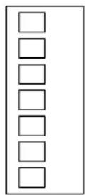
Pin 1 – Contact Closure
Pin 2 - Contact Closure / Applied Voltage +
Pin 3 - Applied Voltage -
Pin 4 – Remote LED +
Pin 5 – Remote LED -
Pin 6 – Aux Relay Contact
Pin 7 – Aux Relay Contact
Control Connections
Control of the switched receptacles can be accomplished by using a switch (contact closure), another SurgeX product such as the SEQ, or by an applied voltage (5 to 30 volts DC). When using a switch, choose a switch with gold contacts for the best long-term reliability.
Connections are made to terminal block pins 1, 2 & 3 as follows:
- Connect switch contacts, a contact closure, or SurgeX control to pins 1 and 2.
Or:
- Connect an applied DC voltage to pins 2 and 3. The positive must be connected to pin 2 and the negative must be connected to pin 3.
Remote Indicator LED
Connecting the Remote LED is optional. If you are using a SurgeX switch plate which has a built in LED and resistor simply connect it as per the instructions supplied with the switch plate. An LED connected to pins 4 and 5 will indicate when the switched receptacles are on. 10mA of current is available at this output, but you must use a series resistor if you are using your own LED. For most LEDs a 1K resistor will provide suitable brightness. If you need less brightness use a larger value of resistor, and if you need more brightness use a smaller value of resistor.
- Connect the LED positive wire to Pin 4
- Connect the LED negative wire to pin 5
Auxiliary Relay Contacts
The auxiliary relay contacts, pins 6 & 7, provide a way to cascade units or to provide confirmation feedback to a central controller. When the switched receptacles are on, the aux relay contacts are closed. There is a 1 second delay before the aux relay closes which gives time for the SurgeX Inrush Current Elimination (ICE ^TM ) circuit to operate. This short delay in combination with the SurgeX ICE ^TM makes it unnecessary to sequence the power to several large loads (such as amplifiers) because of inrush current. SurgeX RT products, when cascaded, can turn on a bank of large amplifiers with no inrush current, and therefore no risk of blowing a circuit breaker.
To cascade two or more RT products, connect the aux relay contacts of one unit to the contact closure input of the next unit. To provide confirmation feedback, connect the aux relay contacts to an input on the central controller.
The relay contacts are rated for 1 amp at 30 V DC.
Brand : SurgeX
Model : SX1115RT
Category : Uncategorized