ADP 36 DSP - Processor Audibax - Free user manual and instructions
Find the device manual for free ADP 36 DSP Audibax in PDF.


| Product Type | Professional Digital Audio Processor |
| Model | ADP 36 DSP |
| Brand | Audibax |
| Number of Input Channels | 3 XLR Female (balanced) |
| Number of Output Channels | 6 XLR Male (balanced) |
| Frequency Response | 20 Hz - 20 kHz (±0.5 dB) |
| Sampling Rate | 96 kHz |
| DSP Processor | 32-bit ADI 21489 |
| A/D and D/A Conversion | 24-bit |
| Input Impedance | >20 kΩ (balanced) |
| Output Impedance | 100 Ω (balanced) |
| Signal-to-Noise Ratio | >105 dB |
| Total Harmonic Distortion | <0.01% (1 kHz, 0 dBu) |
| Channel Separation | >80 dB (1 kHz) |
| Input Sensitivity | ≥ +12 dBu |
| Equalizer | 8-band parametric per input and output |
| Crossover Filters | Bessel, Butterworth, Linkwitz-Riley (12-48 dB/oct) |
| Delay Range | 0-1000 ms per channel |
| Limiter | Adjustable threshold, attack, release per output |
| Control Interfaces | USB (Type B), RS232, Ethernet, Wi-Fi |
| Power Supply | AC 110-240 V, 50/60 Hz |
| Power Consumption | 25 W typical |
| Dimensions (Packing) | 570 x 260 x 90 mm |
| Net Weight | 3 kg |
| Rack Mountable | 1U |
| User Presets | 12 memories |
| Maintenance | Clean with a dry cloth |
Frequently Asked Questions - ADP 36 DSP Audibax
User questions about ADP 36 DSP Audibax
0 question about this device. Answer the ones you know or ask your own.
Ask a new question about this device
Download the instructions for your Processor in PDF format for free! Find your manual ADP 36 DSP - Audibax and take your electronic device back in hand. On this page are published all the documents necessary for the use of your device. ADP 36 DSP by Audibax.
USER MANUAL ADP 36 DSP Audibax
WELCOME TO AUDIBAX....1
SAFETY INSTRUCTIONS....1
IMPORTANT INFORMATION......2
PACKAGE CONTENT....3
SPECIFICATION......3
FEATURES......4
INTERFACE OPERATION....4
FRONT PANEL AND FUNCTIONS....5
REAR PANEL AND FUNCTIONS....5
RS232 CONNECTION DIAGRAM....6
SYSTEM CONFIGURATION......6
BASIC CONNECTION OPERATIONS....12
DISPOSAL....18
ESPAÑOL
BIENVENIDOS A AUDIBAX....19
Thank you very much for choosing Audibax. We hope you enjoy your new product.
It has been developed and designed paying attention to the smallest details, with quality control with European standards supervised by our great team of professional technicians, who work every day to offer our customers the best quality.
We make sure that every Audibax product is built to last long. All our references are made with long lasting materials and our specialists are dedicated to constantly doing quality controls to guarantee the best result.
Please read carefully this manual in order to use your Audibax product in the best way. Do not hesitate to visit our website for further information: www.audibax.com
SAFETY INSTRUCTIONS
GENERAL INFORMATION
- It is important to read and follow the instructions carefully.
- Keep all information and instructions in a secure location.
- Always follow the instructions provided.
- Take note of all safety warnings and never remove them from the equipment.
- Use the equipment only as intended and for its intended purpose.
- Ensure that the stands and/or mounts used are sufficiently stable and compatible for fixed installations. Wall mounts should be properly installed and secured, and the equipment should be installed securely to prevent falls.
- When installing the equipment, be sure to observe the relevant safety regulations in your country.
- Do not install or operate the equipment near sources of heat, such as radiators, heat registers, or ovens, and ensure that it is always cooled sufficiently and cannot overheat.
- Do not place sources of ignition, such as burning candles, on the equipment.
- Keep ventilation slits unobstructed.
- For equipment designed for indoor use only should not be used near water, flammable materials, fluids, or gases. Special outdoor equipment should be used in accordance with the manufacturer's instructions.
- Ensure that no dripping or splashed water can enter the equipment and do not place containers filled with liquids on the equipment.
- Prevent objects from falling into the equipment.
- Use the equipment only with recommended accessories intended by the manufacturer.
- Do not attempt to open or modify the equipment.
- Check all cables after connecting the equipment to prevent accidents or damage due to tripping hazards.
- During transport, take steps to prevent the equipment from falling and causing damage or injury.
- If the equipment is not functioning properly, fluids or objects have gotten inside, or is otherwise damaged, switch it off immediately and unplug it from the power outlet (if applicable). Only authorized, qualified personnel should repair the equipment.
- Clean the equipment with a dry cloth.
- Comply with all applicable disposal laws and separate plastic and paper/cardboard during packaging disposal.
- Keep plastic bags out of the reach of children.
FOR DEVICES DESIGNED TO BE CONNECTED TO THE MAIN POWER SUPPLY:
- ATTENTION: If your equipment has a power cord with a grounding plug, it must be connected to a wall outlet with a ground connection. Never remove the grounding plug from the power cord.
- If your equipment has been exposed to extreme temperature changes, allow it to reach room temperature before turning it on. Otherwise, moisture and condensation may damage the equipment.
- Before plugging in the equipment, make sure that the voltage and frequency of the power outlet match the specifications of the equipment. If the equipment has a voltage selector, only connect it to the power outlet if the values match. If the power cord or adapter does not fit your outlet, contact an electrician.
- Do not step on the power cord. Make sure it is not pinched at the outlet, adapter, or equipment connection.
- Keep the power cord or adapter within reach and disconnect the equipment from the power supply when not in use or when cleaning it. Always unplug the cord or adapter by pulling the plug or adapter, not the cord. Never touch the cord or adapter with wet hands.
- Avoid frequently turning the equipment on and off, as this can reduce its useful life.
- IMPORTANT: Only replace fuses with those of the same type and rating. If a fuse repeatedly blows, contact an authorized service center.
- To completely disconnect the equipment from the power mains, unplug the power cord or adapter from the outlet.
- If your device has a Volex power connector, the mating Volex connector must be unlocked before it can be removed. Be careful when laying cables, as the equipment can slide or fall if the power cord is pulled.
- Unplug the power cord or adapter before an extended period of disuse or in case of lightning strike risk.
- Only install the equipment when it is disconnected from the power source.
- To prevent damage and overheating, qualified personnel should regularly clean and service the equipment depending on ambient conditions like dust, nicotine, and fog.
If the product contains the following symbols, please, read carefully:
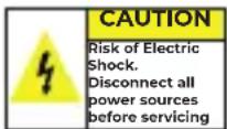
CAUTION: To reduce the risk of electric shock, do not remove cover (or back). There are no user serviceable parts inside. Maintenance and repairs should be exclusively carried out by qualified service personnel.

The warning triangle with lightning symbol indicates dangerous uninsulated voltage inside the unit, which may cause an electrical shock.
The warning triangle with exclamation mark indicates important operating and maintenance instructions.
IMPORTANT INFORMATION
CAUTION! HIGH VOLUMES IN AUDIO PRODUCTS!
This equipment is designed for professional purposes and its commercial use must comply with the applicable national rules and regulations for accident prevention.
As the manufacturer of this product, Audibax has the responsibility to inform you about the potential health risks associated with its use. One such risk is hearing damage caused by prolonged exposure to high volume.
When this product is in use, it can generate high sound-pressure levels that may cause irreversible hearing damage to performers, employees, and audience members.
To prevent this, it is important to avoid exposing yourself or others to volumes exceeding 90 dB for an extended period of time.
PACKAGE CONTENT
1x ADP 24 DSP / ADP 36 DSP / ADP 48 DSP
1x User's manual
1 x Power cord
SPECIFICATION
| Moco | ADP 24 DSP | ADP 36 DSP | ADP 48 DSP | |
| Number of entries | 2 XLR Female Inputs | 3 XLR Female inputs (Canon) | 4 Female XLR Inputs (Canon) | |
| Number of outputs | 4 Male XI R Outputs (Canon) | 6 Male XI R Outputs (Canon) | 8 Male XI R Outputs (Canon) | |
| Input Impedance | Balance: 0.20 k | |||
| Output impedance | Balance: 00 Ω | |||
| Control interface: USB/RS232/Ethernet/Wi -FI | Panel I USB Interface | |||
| Common simulation system ratio | >70dB(1KHz) | |||
| Input sensitivity | ≥+12dBu | |||
| Frequency response | 20Hz-20KHz(-0.5dB) | |||
| Signal to noise ratio | >10s dB | |||
| Distortion Armonica | <0.01% OUTPU.T=0dBu/1KHz | |||
| Separation entre canales | >80dB(1KHz) | |||
| Input channel | Mute | Input mute control for each channel | ||
| Delay | Each input channel has an individual delay control, the adjustment range is 0-1000ms, loss than 10ms, the stop distance is 21 μs; >10ms, the stop distance is 1ms | |||
| Polarity | In phase(1) & reverse phase(-) | |||
| Parametric Localizer | 8 parameters are set for each input channel. Adjusting parameters under PFQ are: center frequency point: 20Hz-20KHz, value: 0.404-28.85, step distance: 0.002 OCT gain: -20dB~+12dB step distance: 0.1dB Lo-shel, Hi-shel, center frequency point: 20 Hz -20KHz, Q value is not adjustable; Gain: -20dB~+12dB Stop is 0.1dB | |||
| Output channel | Mute | Output mute control for each channel | ||
| Input | Each output channel can select from the number of available inputs | |||
| Gain | Adjusting range: +12dB to -56dB, step is 0.1dB | |||
| Delay | Each input channel has an individual delay control, the adjustment range is 0-1000ms, less than 10ms, the step distance is 21 μs; >10ms, the step distance is 1ms | |||
| Polarity | In phase(+) & reverse phase(-) | |||
| Parametric Localizer | 8 parameters can be set for each output channel. Adjusting parameters under PFQ are: center frequency point: 20Hz 20KHz, value: 0.404 28.85, stop distance: 0.002 OCT gain: -20dB~+12dB step distance: 0.1dB Lo-shel, Hi-shel, Center frequency point: 20Hz 20KHz, Q value can not be adjusted; Gain: 20dB~+12dB Step is 0.1dB | |||
| Frequency Divider | Each output channel can be individually configured with a low-pass filter (LPF) and a high-pass filter (HPF) filter type: LinkWitz Riley/Bossel/Butterworth Frequency turning point: 20Hz 20k-z attenuation slope: Bossel/Butterworth 12/8/24/36/18dB, LinkWitz-Riley 12/2/36/18 dB | |||
| Limiter | Each output channel can be set separately / miter, adjustable parameters as: threshold value ±20dB μ, step distance: 1dB μ Start time: 0.3ms-100ms, less than 1ms, step distance: 0.1ms; Release time: can be set as 2 times, 4 times, 6 times, 8 times, 16 times, 32 times the starting time | |||
| Processor Type | 96kHz sampling frequency, 32-b, DSP processor, 24-bitA/D and D/A conversion | |||
| Energy consumption | ±25W | |||
| Power supply | AC 110V/240V 50Hz/60Hz | |||
| Net weight | 3kg | |||
| Packing size | 570×260×90mm | |||
FEATURES
This device is a Professional Audio Processor based on DSPtechnology, with powerful functions and 1U frame height. It comes with 2 in 4 out, 3 in 6 out, 4 in 8 out, flexible for several X-over modes. Especially suitable for use at the scene of the performance.
- 96kHz Frequency, ADI 21489 32-bit DSP processor, 24-bit A/D and D/A conversion.
- USB, RS232 interface, network port and WiFi are available for PC software.
- 12 preset of user settings.
- 8-band parametric equalizer, Gain(-20dB-12dB), Lo-shel and Hi-shelf for each channel.
- Adjustable HPF/ LPF. Type: Bessle, Butterworth (12dB, 18dB, 24dB, 36dB, 48dB) or LinkWitz-Riley (12dB, 24dB, 36dB, 48dB).
- The parameters of HPF / LPF can be adjusted independently and the asymmetric crossover functions can be achieved.
- Each input/output has Gain, Delay, Phase and mute and the max delay 1000MS. The delay unit can be selected in milliseconds (ms), meters (m) ft (ft).
- The output channel can also control the voltage limit and select the inputs available on the unit.
INTERFACE OPERATION
Connection types for control:
This series are with USB/ETHERNET/RS232/WI-Fi.
Signal level:
As with other signal processing equipment, the device should be with suitable signal level to reduce signal/noise. The unit has menu settings for adjustment.
To select signal level, should be select max level ±6dB , at this time, LED indicator lights up. As we add 3dB, so at this time, peaking clipping is actually 9dB. To operate EQ, should reduce input level to avoid peak clipping of gain. Attention: Max input level in technical parameter form is not safety level but peaking level. To make sure peaking clipping is not less than next device, and keep some extra level.
Ground connecting:
All ground terminals of the unit must be operational, as well as the audio sockets must be in their correct pin. The main O/V power supply has a circuit breaker fuse, do not operate the unit if the fuse is damaged or has not been checked by a technician in case of breakdown.
FRONT PANEL AND FUNCTIONS

-
B-type USB interface for PC software.
-
Display screen.
-
Function keys:
Back: the previous function selection; Next: the next function selection.
Enter: after the parameters are adjusted, enter to determine.
ESC: back to the default interface.
BYPASS: long press BYPASS to access the engineering lock setting interface; SYSTEM: enter/exit the SYSTEM setting interface.
-
Coding wheel: Selection of single functional parameters.
-
Parameter adjustment coding wheel.
-
VU meter signal indicator present luminous signal indicator.
-
Shortcut key for mute/edit, short press for mute, long press for channel settings.
REAR PANEL AND FUNCTIONS
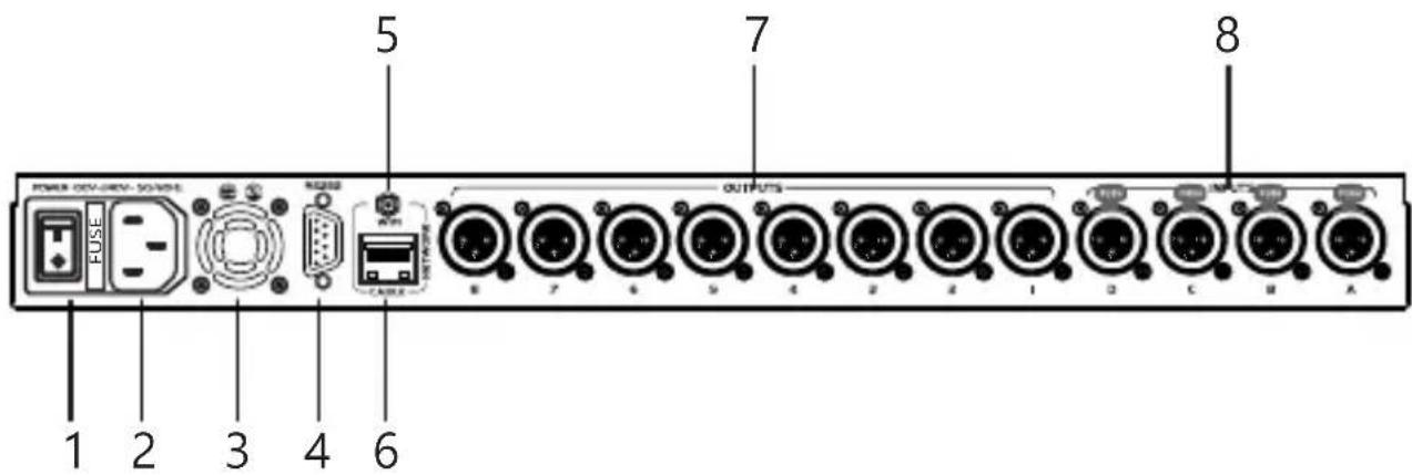
-
Power switch
-
IEC connector (C14): AC power input, for IEC cables (C13) with male Schuco (CEE7) termination (supplied in the unit).
-
Cooling fan.
-
RS232 port: used to connect with a PC or central control device to control this device.
-
Antenna port: to connect with WiFi signals.
-
Ethernet Jack: Connect the unit to a router.
-
Audio output terminals, identified as jack 1 to 8 (Mod ADP 48 DSP) 1 to 6 (Mod ADP 36 DSP) 1 to 4 (Mod ADP 24 DSP).
The unit's
- Input terminals:
4 input channels (ADP48DSP Mod) 3 input channels (ADP36DSP mod) 2 input channels (ADP 24 DSP Mod), The unit's input terminals (XLR Female) govern under standard configuration, pin 1 (mesh or ground) pin 2 (positive or live +) pin 3 (negative or return -)
RS232 CONNECTION DIAGRAM
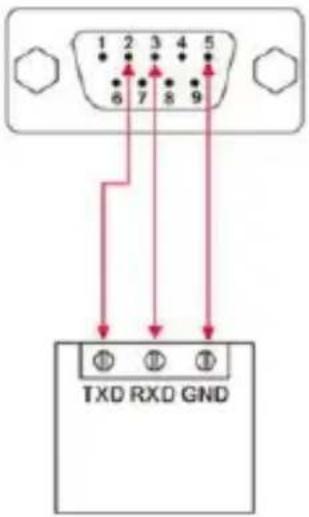
RS232 port connection diagram
RS-232
Turn on the unit, the screen will show the message "Please Wait, Loading..." as shown in the image
Please wait
Loading.....
Once booting is complete, the screen will inform you of the name of the Wi-Fi link offered by the unit, by default HMlink-xxx (note if the factory settings have not been changed).
WIFI:
HMLink-xxxx
Once booting is complete, the screen will inform you of the name of the Wi-Fi link offered by the unit, by default HMlink-xxx (note if the factory settings have not been changed).en el caso de que usted ya haya grabado o memorizado algun parametro con un nombre predeterminado (por ejemplo "Salon de eventos) lo mostrar al iniciar la unidad
Send Data OK
Mode:1
Name:USER1
If for 15 seconds, no button on the front panel is manipulated, the screen will enter standby or information mode.
Input channel configuration:
The control keys (fig7) arranged in alphabetical order (depending on version) correspond to the input settings. These keys have 2 functions:
-
If you briefly press the key (example A), the red LED housed therein will illuminate, indicating that you have activated the MUTE function for that channel. If you press briefly again, the LED will turn off, leaving said channel open.
-
If you press long (more than 2 seconds) the unit enters channel editing mode (a red LED will light up at the top of the channel vumeter (Fig6) indicating the channel that is going to be modified. If you press again Perform a long press, the vumeter LED (Fig6) will light up, indicating that the channel is free
The unit has a set of keys to navigate and vary functions within its setting, (fig3) press BACK to return to the previous menu, press NEXT to advance to the next menu, press ENTER to select a menu, turn the Freq wheel (fig4) to toggle through the menu options, Rotate the Gain/Q wheel(s) (fig5) to vary the values (both wheels have the same function) Press ESC to exit to the main menu
Press SYSTEM to enter the unit configuration menu.
- Channel Input Gain Adjustment:
InA Gain: 0.0dB
Noise Gate: - 80dB
Press the A button on the front panel (fig7) for two seconds, the information that appears on the screen will be shown, turn the FREQ wheel (Fig4) to select between Gain or Noise Gate, Turn the GAINQ Wheel (Fig5) to vary The values, the GAIN values range from -36dB to +12dB, by default its value is 0.0dB, the Noise Gate values range from -120dB to -20dB, by default its value is -80dB.
- Press NEXT to enter polarity setting. The interface is shown as follows:
InA Polarity
Pol=Invert
Press the NEXT key to enter the Polarity adjustment. The unit offers the possibility of varying it 180^ (invert it) Turn the FREQ wheel to alternate between "NORMAL or INVERT"
- Press NEXT to enter delay setting, the unit will display the following information:
InA Delay
x10.0 Dly=178.992ms
Each channel has an independent delay control, by default the unit is set to Meters Seconds ms, with a range of 0 to 1000ms. Turn the FREQ wheel to increase or decrease the range (as shown in the image above) in
The interface. Rotate the Gain/Q value to adjust each parameter.
- Press NEXT to enter parametric equalization mode:
InA EQ1 14991Hz
+10.0dB 0.752 HShf
The system consists of a parametric equalizer with 8 points per channel, indicated by EQ1, EQ2 and successive ones, within each equalization point you can adjust the frequency with values from 20Hz to 20Khz, the gain indicated in dB, with values of -20dB to +12dB, the value of Q, with values from 0.404 to 28.9.
To navigate through the options in this menu Turn the FREQ wheel and change values with the GAIN or Q wheels.
Output channel configuration:
The output configuration keys (Fig 8), depending on the model (ADP24DSP from 1 to 4) (ADP36DSP from 1 to 6) (ADP48DSP from 1 to 8) have 2 types of keystrokes:
1) Brief press activates or deactivates the MUTE function, when MUTE is activated the red LED at the top of the button remains on, another brief press will turn off said LED and the channel will remain open.
2) Long press (more than 2 sec) enters the channel configuration mode, The unit has a set of keys to navigate and vary functions within its setting, (fig3) press BACK, to return to the previous menu, press NEXT to advance to the next menu, press ENTER to select a menu, turn the Freq wheel (fig4) to cycle through the menu options, Turn the Gain/Q wheel(s) (fig5) to vary the values (both wheels have the same function)
Press ESC to exit to the main menu
Press SYSTEM to enter the unit configuration menu.
- Gain and output routing configuration, press the key of the output channel to be adjusted for 2 seconds, the interface will display this menu:
Out1 Gain: 3.0dB A: ON B: OF C: OF D: OF
The gain adjustment levels are designated in a range of -48dB to +12dB, Turn the FREQ wheel to select the Gain section, turn the GAIN or Q wheel/s to increase or decrease the values.
Routing, Turn. the FREQ wheel to access the source selection (A,B,C,Ddepending on version) the route options vary between ON/OFF, ON the selected source is activated, OFF the selected source is off, you can route as many sources as exit. as required or available on each channel (depending on model).
2 Output polarity, Press NEXT to enter polarity adjustment, the interface will display the
Out1 Polarity
Pol=Invert
The polarity of each output channel can be adjusted independently, by default the unit sends it in "normal" format to invert the polarity (180°). Turn the FREQ Wheel, you can alternate between "Normal" (0°) or "invert" (180°). Or rotate FREQ/GAIN/Q to adjust the polarity.
Out1 Delay
x10.0 Dly=178.992ms
Each channel has an independent delay control, by default the unit is set in Meters Seconds plus, with a range of 0 to 1000ms. Turn the FREQ wheel to increase or decrease the range.
- Crossover (frequency divider) adjustment Press NEXT to and the interface will display the following message4. Press the Next button to enter the frequency division setting
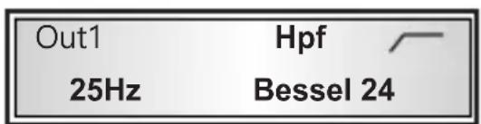
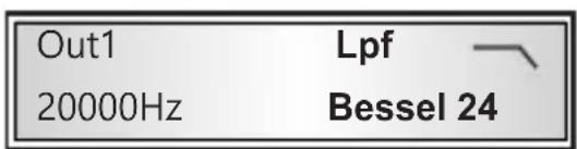
Each channel has the option of 2 types of IIR and FIR filters (FIR filters can only be manipulated from the graphical interface via PC (USB, RS232 or ETHERNET) IIR filters (Bessel, Butterworth, Linkwitz) have an adjustment range of 20hz at 20khz, with an attenuation slope of 18dB, 24dB, 36dB, 48dB per octave, except for the Linkwitz-Relay filter which has values of 12dB, 24dB, 36dB, 48dB per octave
Turn the FREQ wheel to navigate between options and turn the GAIN/Q wheel to increase or decrease them.
- Setting the output compressor, turn the NEXT wheel and the interface will show the following image:
Out1 Comp OF +12.0dB
100ms Atk 2 1:1
Each output channel has an independent audio compressor, this compressor offers the following functions, ON/OF to activate it, attenuation range from -6dB to +12dB, with step values of 0.1dB, start time from 3ms to 100ms, release time: 2/4/6/8/16/32 times the start time, compression ratio 1:1 to 128.
Press the BYPASS key (fig3) turn the FREQ wheel to navigate between the options, turn the GAIN/Q wheel(s) to increase or decrease them.
- Parametric output equalizer, press NEXT and the interface will show the following image
Out1 EQ1 14991Hz
+10.0dB 0.752 HShf
Each output channel consists of a parametric equalizer with 8 points per channel, indicated by EQ1, EQ2 and so on. Within each equalization point you can adjust the frequency with values from 20Hz to 20Khz, the gain indicated in dB, with values from -20dB to +12dB, the value of Q, with values from 0.404 to 28.9
Turn the FREQ wheel to navigate between options and turn the GAIN/Q wheel to increase or decrease them.
System menu:
Press the SYSTEM key (fig3) to access the system menu, by pressing between the NEXT and BACK keys we can navigate between the different options. Pressing ENTER we will select the menu to configure (fig3).
- Load Pro, storage and copying of profiles, in this section you can copy configurations between channels and store configuration profiles already made
When you press ENTER the interface will show this image
SYSTEM SETUP MENU
- Load Pro
Press ENTER again and with the FREQ wheel (fig4) toggle between: Load or copy channels.
1) Load Group (or user memory)
After pressing ENTER, the interface will show the following image
Select and Load
1: USER 1
Turn the FREQ wheel to select one of the memories, the unit offers a total of 12 banks to store groups or settings, turn the GAIN/Q wheel to select one of them and press ENTER to confirm.
2) Copy or duplicate channels
Press ENTER and the interface will show the following image
Copy from:InputA to:InputC
Turn the FREQ wheel to select the channel to duplicate or copy, turn the GAIN/Q wheel to select between input (A,B,C,D) or output (1 to 8) (depending on model) press ENTER to confirm the selection and Turn the GAIN/Q wheel again to select the destination channel, press ENTER again to confirm copy.
- Save Pro saved data
Once you have the unit configured, you can save said configuration within the unit. Press the ENTER key and turn the FREQ wheel to select a bank (User1,2, etc.) to store the session. Press ENTER again to confirm the save.
SYSTEM SETUP MENU
-
Save Pro
-
ID (device number) configuration
Set the machine identification number.
SYSTEM SETUP MENU
- Device ID Setup
Press ENTER to go to the settings page. Rotate the FREQ/Gain/Q value to adjust the device number value, you can toggle between 1 to 250, press ENTER again to confirm.
4.Password
You can change the password, the default is 1111, to one you can remember, so that no one can tamper with the unit without your supervision.
SYSTEM SETUP MENU
- Password
Configure the speed of the RS232 port, according to the needs of your computer.
SYSTEM SETUP MENU
6.RS232 Baudrate
After pressing Enter, turn FREQ/GAIN/Q to adjust the baud rate.
- Reset to factory settings
Restore the unit to its factory settings and the display interface is as follows:
SYSTEM SETUP MENU
. 7 Factory Reset
After pressing ENTER, turn FREQ to choose YES (confirm to restore factory settings) or NO (quit). After resuming factory settings, the system begins to initialize internally.
The interface is shown as follows:
EEPROM INIT
Waiting...
- Network interface configuration (ETHERNET fig 6)
Configure the IP address interface, shown as follows:
SYSTEM SETUP MENU
- IP Address
Press the ENTER key and the interface will offer you 2 options, 1 Automatic 2 manual
Automatic
Manual
Turn FREQ to select Automatic and click Enter to obtain IP automatically, if your unit is connected to a router with CAT-5/6 cabling and RJ-45 connector
Turn the FREQ wheel and select Manual and press ENTER to enter manual IP configuration mode.
-
-
- 0
-
Turn the FREQ wheel to select network segments (0 to 254) per box, turn the GAIN/Q wheel to select a value per box, no need to fill in anything else, if you assign an IP within the range of your router, the software will find the unit with the assigned IP.
- System information
Audibax Dsp Control
V1.0.0-20200917
Press Enter again to display the current device chip ID as follows:
Audibax Dsp Control
Chip ID 39ffd7-200917
BASIC CONNECTION OPERATIONS
Introduction:
- RS232: Please use the proper cable to connect, connect it correctly when the indicator lights up and then you can control it by PC software.
- Use a USB 2.0 cable, with a type A connector for your PC and a type B connector at the other end for the unit.
- WiFi: Open the device to search for MhLink-xxxx. Enter the password "12345678" to connect.
- Connect an RJ45 Cable to the unit in said port, you can also connect it directly to your PC as long as your PC interface is in the same NETWORK range as the unit.
Example: if the unit has an IP 192.168.1.128, your computer must have a fixed IP assigned within the same range, in this case, configure your network card with the following data i.p. 192.168.1.100
netmask 255.255.255.0
gateway 192.168.1.1
In this way, since the unit is within the same network range as your PC, you can access said control.
Yeah. You connect the unit to a router and it has the "Automatic" assignment mode, you can see the IP assigned by the router in the information interface, with your PC connected to the same router, you will be able to access the unit without problem.
Introduction to Audibax DSPControl software
- Softwarte Installation Audibax DSPControl
Discasela Ultima version of the software from https://audibax.com/support/downloads/ - Execute the Audibax DSPControl.exe file and press the upper right button "do not connect"
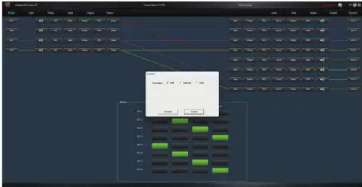
A menu will open where you can select the unit connection mode
USB
Network
Com
USB, connect a USB type A cable to the computer and type B to the unit front. Select USB and Connect in the MHController software.
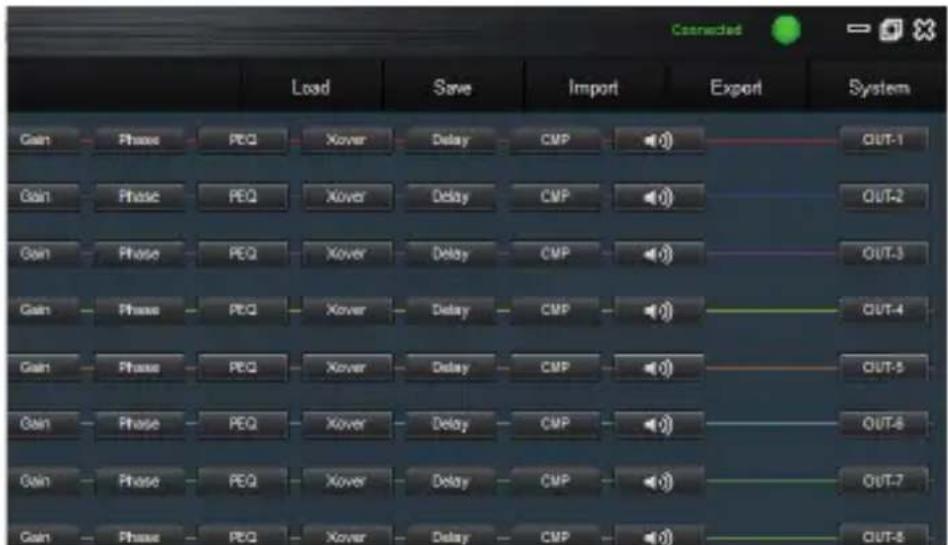
A successful connection will illuminate the connected pilot in green can already operate the unit.
Network
Connect a CAT-5/6 cable to the unit to the Ethernet port and connect it to a router to share IP address, select in the Network connection menu and run the Search button, to locate the routed unit.
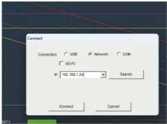
(For Wi-Fi connectivity, the procedure is the same, just indicate IP of the WiFi connection)
Press Connect and you can operate the unit
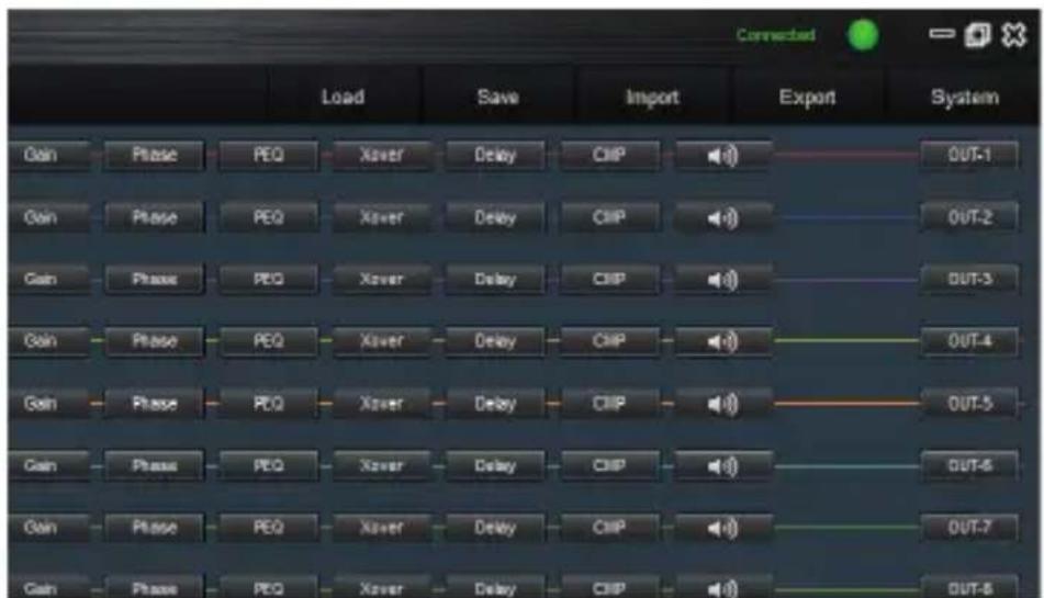
RS232/com connection
Connect the USB device to RS232 on your PC (or a RS232 terminal direct to the unit) and end that the terminals have the correct configuration as in the following diagram:
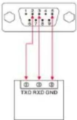
RS-232
Select com in the connection panel, in the drop -down with the assigned port number (in the Com3 example) and the speed in baud (by default 19200)
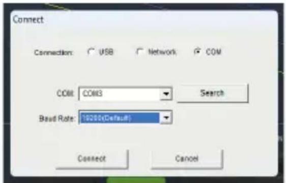
Press Connect and you can operate the unit.
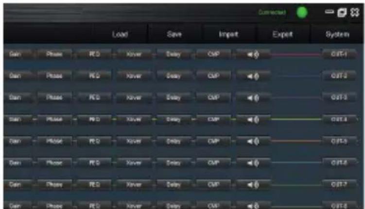
Once we have established connection, the processor graph unit can operate.
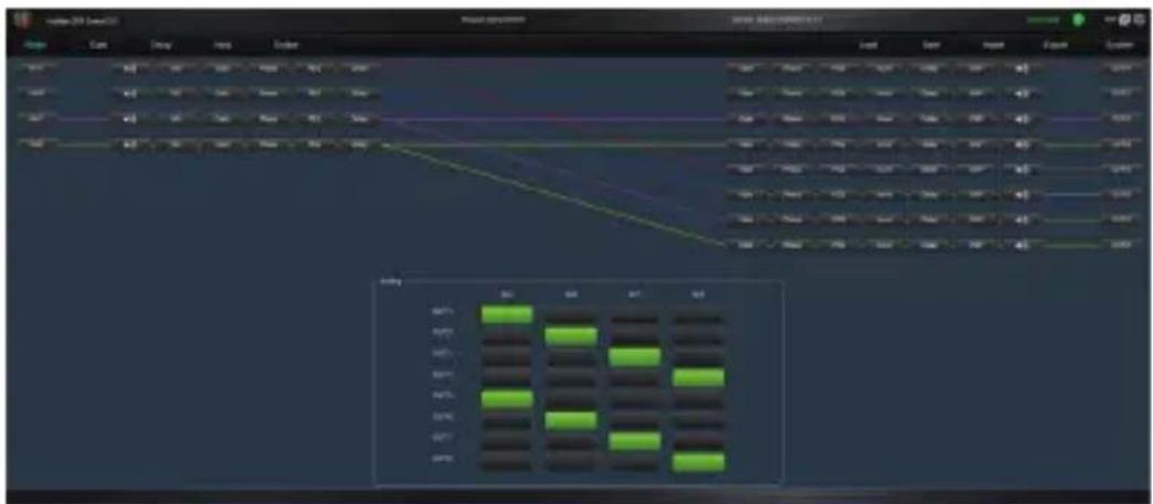
Route
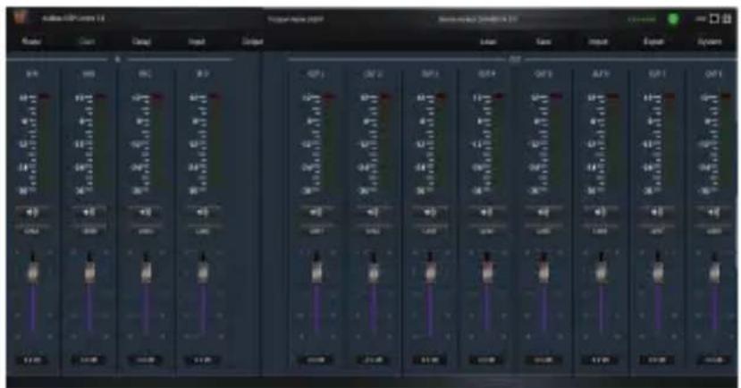
GAIN (Input and output levels)
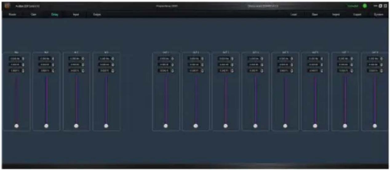
Delay (signal delay input and output)
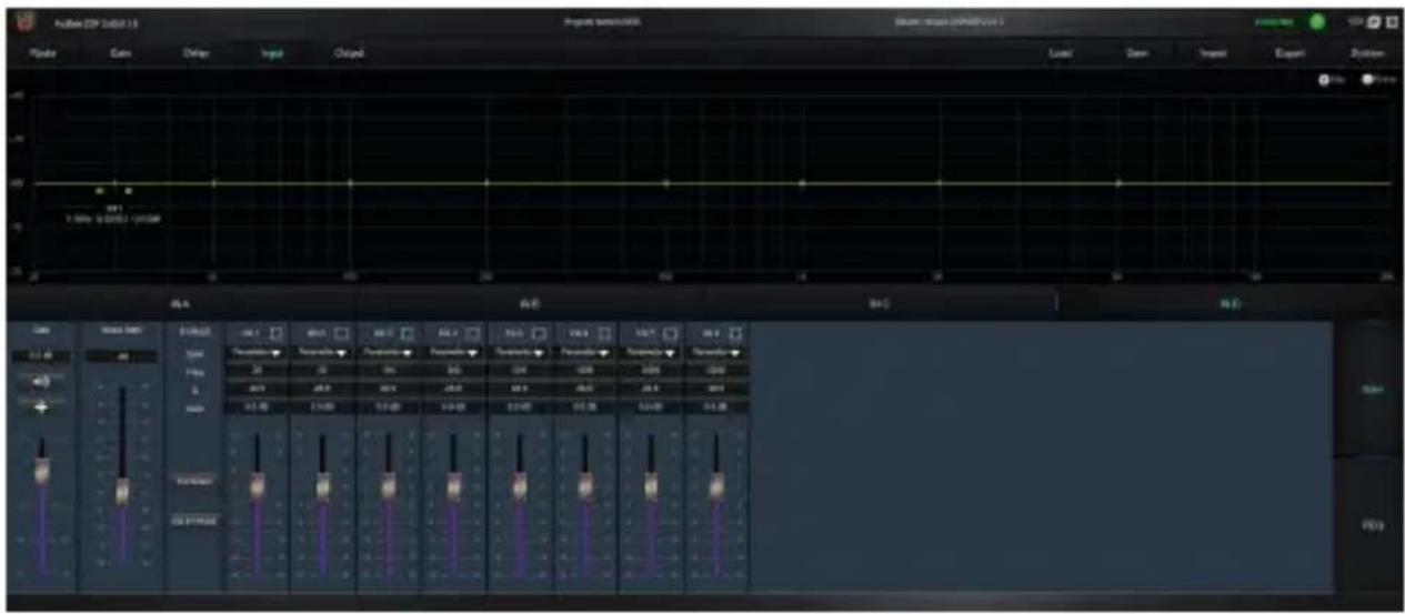
Input (level adjustment and input equalization)
Output (output level adjustment, output equalization, crossover and output compressor)
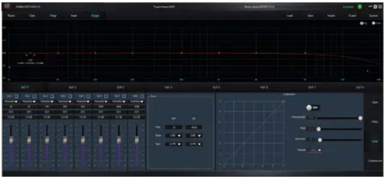
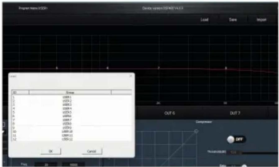
LOAD (load a user memory or profile)
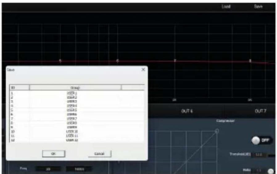
Save (keep a user memory or profile)
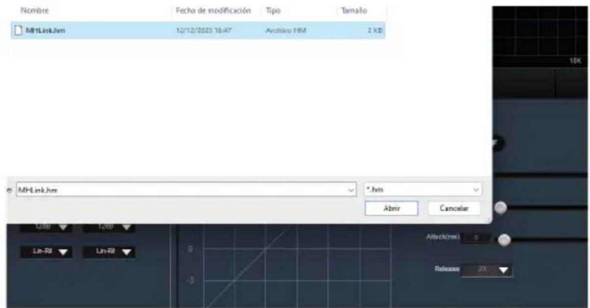
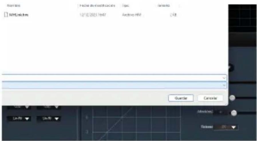
Import (import a configuration file previously exported extension .hm)
Export (exports the total configuration configuration configured, and can assign a name)
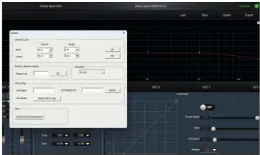
System (extra parameter settings, such as: make copies between channels, change the configuration password, change the name and key of the Wi-Fi network)
DISPOSAL

Packaging:
- The packaging can be recycled using standard disposal methods and reintroduced into the reusable material cycle.
- Please follow the laws and regulations regarding disposal and recycling of packaging in your country.
Device:
- This device is subject to the Waste Electrical and Electronic Equipment (WEEE) Directive of the European Union. Used appliances should not be disposed of with household waste. Used device must be disposed of through an approved disposal company or a municipal disposal facility. Please comply with the applicable regulations in your country.
- Please follow all the disposal laws and regulations in your country.
- As a customer, you can obtain information on environmentally-friendly disposal options from the product seller or the appropriate regional authorities.
BIENVENIDO A AUDIBAX
Please wait Loading.....
Conexión RS232/COM
RECICLAJE
Embalaje:

- ESPAÑOL
- SAFETY INSTRUCTIONS
- GENERAL INFORMATION
- FOR DEVICES DESIGNED TO BE CONNECTED TO THE MAIN POWER SUPPLY:
- IMPORTANT INFORMATION
- PACKAGE CONTENT
- FEATURES
- INTERFACE OPERATION
- FRONT PANEL AND FUNCTIONS
- REAR PANEL AND FUNCTIONS
- RS232 CONNECTION DIAGRAM
- System menu:
- BASIC CONNECTION OPERATIONS
- Introduction:
- Network
- DISPOSAL
- Packaging:
- Device:
- BIENVENIDO A AUDIBAX
- Conexión RS232/COM
- RECICLAJE
- Embalaje:
Brand : Audibax
Model : ADP 36 DSP
Category : Processor