CA-BC-SUZ.004 - Car accessory PIONEER - Free user manual and instructions
Find the device manual for free CA-BC-SUZ.004 PIONEER in PDF.


| Product Type | Steering Wheel Control Interface / OEM Reverse Camera Retention Kit |
| Brand | Pioneer |
| Model | CA-BC-SUZ.004 |
| Compatibility | Suzuki vehicles with OEM reverse camera |
| Kit Contents | Wiring harness with resistors, connectors, and terminal connectors; installation manual |
| Cable Colors | Green, black, red |
| Connectors | Yellow connectors, camera connector (radio side), car connector |
| Input Voltage | 12V DC (typical automotive) |
| Signal Types | Reverse input signal, camera video, steering wheel control signals |
| Installation Requirement | Professional installation mandatory |
| Safety Notes | Manufacturer/dealer not liable for incidental or indirect damages; technical changes possible |
| Dimensions (approx.) | 4.5 x 3 x 1 inches |
| Weight (approx.) | 0.2 lbs |
| Operating Temperature | -20°C to 70°C |
| Storage Temperature | -30°C to 80°C |
| Material | Plastic housing, copper wiring |
| Color | Black |
| Warranty | 1 year limited warranty |
| Documentation | Free user manual available for download in PDF format |
Frequently Asked Questions - CA-BC-SUZ.004 PIONEER
User questions about CA-BC-SUZ.004 PIONEER
0 question about this device. Answer the ones you know or ask your own.
Ask a new question about this device
Download the instructions for your Car accessory in PDF format for free! Find your manual CA-BC-SUZ.004 - PIONEER and take your electronic device back in hand. On this page are published all the documents necessary for the use of your device. CA-BC-SUZ.004 by PIONEER.
USER MANUAL CA-BC-SUZ.004 PIONEER
Steering wheel control interface installation kit for:
SUZUKI
Model: For Suzuki vehicles with OEM Reverse Camera;
Kit content: OEM Rear View Camera Retention Kit
Customer code: CA-BC-SUZ.004

natural_image
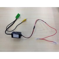
Electrical wiring with three colored components (green, black, red) and terminal connectors (no text or symbols visible)INSTALLATION MANUAL
All installation work must be performed by a qualified professional installer only.
The manufacturer / dealer is not liable for any kind of incidental or indirect damages.
05/2016 ALL RIGHTS RESERVED. Technical changes possible. No liability for misprints. RO
All installation work must be performed by a qualified professional installer only.
The manufacturer / dealer is not liable for any kind of incidental or indirect damages.
05/2016 ALL RIGHTS RESERVED. Technical changes possible. No liability for misprints.

natural_image
Electrical wiring diagram showing connections between components including a black resistor, yellow connectors, and red wires (no text or symbols)Connect cables to the side as follow:
1- to CAMERA CONNECTOR (RADIO SIDE)
2- to GND (CHASSIS)
3- to CAR CONNECTOR
4- REVERSE INPUT SIGNAL: connect from RADIO to CAR



Brand : PIONEER
Model : CA-BC-SUZ.004
Category : Car accessory