TXP4.3500D - Receiver Soundstream - Free user manual and instructions
Find the device manual for free TXP4.3500D Soundstream in PDF.


| Product Type | 4-Channel Class D Car Amplifier |
| Model | TXP4.3500D |
| Brand | Soundstream |
| Dimensions (W x H x D) | 8.25 x 2.75 x 7.25 inches |
| Operating Voltage | 9V - 16V DC |
| RMS Power (4 ohm stereo) | 140 W x 4 |
| RMS Power (2 ohm stereo) | 235 W x 4 |
| RMS Power (1 ohm stereo) | 375 W x 4 |
| Bridged Power (2 ohm) | 700 W x 2 |
| Max Power | 3,500 W |
| Total Harmonic Distortion (THD) | < 0.3% |
| Signal-to-Noise Ratio | 105 dB |
| Input Sensitivity | 200 mV - 6 V |
| High-Pass Filter (HPF) | 15 Hz - 6 kHz, 12 dB/octave |
| Low-Pass Filter (LPF) | 50 Hz - 6 kHz, 12 dB/octave |
| Bass Boost | 0 - 12 dB at 50 Hz |
| Frequency Response | 20 Hz - 20 kHz |
| Input Type | RCA low-level (line input) |
| Protection Features | Overload, thermal, power & protection LED |
| Additional Features | Bridgeable, TRI-mode, soft start, muting, silver plated terminals, remote bass control |
Frequently Asked Questions - TXP4.3500D Soundstream
User questions about TXP4.3500D Soundstream
0 question about this device. Answer the ones you know or ask your own.
Ask a new question about this device
Download the instructions for your Receiver in PDF format for free! Find your manual TXP4.3500D - Soundstream and take your electronic device back in hand. On this page are published all the documents necessary for the use of your device. TXP4.3500D by Soundstream.
USER MANUAL TXP4.3500D Soundstream
TXP2.6500D TXP4.3500D TXP1.3500D TXP1.6000D TXP1.12000D TXP1.18000D
Compact Size High Power Amplifier
PLEASE READ THIS MANUAL BEFORE INSTARAGE AND USING AMPLIFIER
Congratulations on your Purchase
Your new high fidelity bridges are stored ____ amplifier is designed to deliver maximum enjoyment and years of trouble free service. The quality of the installation may affect the performance and the reliability of your products
Features
●Class "D" High Efficiency Mono Block Car Amplifier
● Bridgeable & TRI-Mode Operation.
- Constabilty Variable 12ds/Octane High-Pak - Subopter Variable Enterprise (for Deep Res)
●Enforced Bass Bound *12dB (S60Hz)
■Silver Plated RCA, Power & Speaker Terminal
●Soft Start & Mating
●Downsud Thermal
●Power & Protection No. 104 ●Base Land Barrota Control(16 4th)
Precautions: Read First!
●The amplifier needs to be installed by an authorised installer
●Negative battery terminal must be disconnected before any electrical connections are made.
So sure choose a location that provides substantial ventilation for the amplifier. This most
preferred locations would be in you bar's trunk, under the front seats or on the back was
of a factor.
- The location choice should provide allowed 2" of clearance above the amplifier for adequate
verifiatic
- All the oddler is to be mounted vertically be sure that it is in a place where adequate our
will flow along the length of its heat sink fins for cooling.
NEVERMOHN the shenzhen up side down, this will cause the heat to amplify paying thermal shutdown or possible permanent damage.
Figure 1. The following is possible:
●NEVERMO
measures
●The sure to mount the amplifier to a silicon, sold surface which will not cite way under the
stress of a written stop or accident.
Blade suggests the moving price against a premium that is lost. Take out business
- Make the best to the following screws will not be tested by writing or other critical parts of your car when installed.
2017年1月1日
■ Set on the code (with) is used to define for a specified reference of us
• Credy the actuate
- Warranty may be void if proper installation technique and cabling is not used.
1
SPECIFICATION
TXP1.12000D
1.300w x 1:04-nbm Stereo
2.100m x 7.0 Johm Stargn
4.100m x 1 @ 1-ohm stereo
12.000m MAX Power
12.000 MARK TIPS - 0.7%
TRU: 40.5%
Input Sensitivity: 200Mv-b
HPF:15.80Hz
LPF:80-20KHz
Bass Boost: 0-12dB 50Hz Bass Boost
Frequency Response: 20-20KHz
S/N:105dB
Working Voltage: 9V-10V DC
Distortion Clip Lights
With Remote Controls
Size:8.25" w×2.75" h×7.25"
TXP1.18000D
1.800w x 1 @4-ohm Stereo
3.600w x 1 @ 2-nhm Staten
7.000px x 1 @ 1-ohm Stereo
18.050w MAX Power
14.0268 MAX. PERI THU: -0.10
THU: 0.5%
input sensitivity: 200ms-6s
HPF:15-80Hz
LPF:80-20KHz
Bass Boost: 0-12dB 50Hz Bass Boost
Frequency Response: 20-20KHz
S/N: 105dB
Working Voltage: 9V-16V DC
Distortion Clip Lights
With Remote Control
Size: 8.25" w=2.75" h=10.5"
SPECIFICATION
TXP2.65000
400w x 2 @ 4 ohm Stereo
700m×2≈2-ohm Stereo
1.250w×7×1 ohm Stereo
1,230W×2 @ 1-ohm Stered 2,500 mm x 1 @ 2 ahm Baidood
2,500mm x 1 @ 2-inch
6,500W MAX
THD: <0.3%
Input Sensitivity: 200Mv-6V
HPF-15-1KHz
LPF-50-10KHz
841,36-10Hz
Bass Boom;
S/N: 105dB
Working Voltage: 9V-16V DC
Distortion Clip Lights
With Remote Controls
Size: 8.25" w×2.75" b×5.75"
TXP4.3500D
140w x 4 # 4-ohm Stereo
235w×4@2-ohm Stereo
375w x 4 w 1 ohm Stereo
375M x 4 @ 10th Stated 700-2.9.3 ahm Bridged
700W x 2 @ 2-inch B
3,500M MAX
THD: <0.3%
Input Sensitivity: 200Mv-6V
HPF:15-6KHz:12dB
LPF-50-6KHx 12dB
E: 1.50 GHz 12dB Page Reports: 0, 12dB
Bass Boost
S/N:105dB
Working Voltage: 9V-16V DC
Distortion Clip Lights
Size: 8.25" w×2.75" h×7.25"
股票代码:002517
TXP1.60000
700w x 1 = 4-ohm Stereo
1.200w x 1 in 2 ohm Stover
1,200m x 1 @ 2-inch Scared 3.250mm x 1 @ 1 inch Stres
2,350W x 1 = 1-0mm
6.000MM MAX POWER
THD: <0.3%
Input Sensitivity: 200Mv-6V
HPF 15-80Hz
1 PF: 80.70KVH
LFP: 10-24MHz Bass Boost: D-17dB 5GHz Bass Boost
Bass boost: 0-12dB 3GHz Bass boost
Frequency Response: 20-20kHz
5/N:105dB
Working Voltage: 9V-16V DC
Distortion Clip Lights
With Remote Control
Size: 8.25" w x 2.75" h x 5.75"
身
2
INSTALLATION & CONNECTIONS
MOUNTING
-
After reading precaution, decide where you are going to install the unit. Also, see Fig. 1
-
Once the location has been determinant, place the another orientation, given a left to
pen of checkmark the four holes to be drilled for mounting. NEVER use the angular as
a template for drilling. It is very easy to damage the amplifier surface in this manner.
- Remove amplifier. Drill four 3.5 min holes into mounting surface. If you want to mount
The amplifier to MOF or wood panel, drill fuse 3.0 m/s diameter holes into mounting surface.
- If possible, test the system to ensure it is operating correctly before final recording of
the ampitlar
- Mount the smaller using the supplied 4 self-lapping winner.
INPUT CONNECTIONS
This amplifier will extend low level in-vitri units. Low level is the same as low level. The low
This is not a result. All accept the other inputs only. Conven in the case of the case. This is a result that signals its oriented percent PCA cables. It is preferred to use low broadbands in the
Amplifier if the head unit is equipped with the low level corpus. If not, you can use a "high
"to low converter" available through your local car dealership.
Connect the low-level level RCA cable from the head unit, or signal processor, to the
the level input on the amplifier. See Fig 2 system wiring diagrams
POWER CONNECTIONS
It is important to have good quality power and ground connections. Remember to complete
an electrical circuit, the ground connection is just as important as the positive power
connection. Before any power connections are made, disconnect the ground cable at the
bunny.
When the power supply lead, memory backup lead of ground lead are extended use a free
(AWGS) or larger automotive grade cable which will withstand friction and heat to safe
We have already been according to the law of the jurisdiction.
GND=Connect the proper gauge ground wire to the amplifier 'GND' terminal. Locate the
position on the chassis of the car to which the amplifier is to be grounded. The surface must
be free from any point of oil. This can be accomplished with a small grinding oil, same paper at wire/sheel. MOTE: Do not around the amplifier to the frame of the cor. The frame
Paper of West Street. Note: Do not ground the aggregate to the three is the car. The hands in most cars and trucks is not grounded, to the mechanic (body). Use Solder or plamp ring to
connect the ground wire. Pre-drill the prapped chassis to bolt the grounding terminal with
nut, bolt and lick washers. Insulate metal and connector with paint or silicon to prevent
nust and oxidation. Silicon also works great to prevent nuts and bolls from working loose in
a hand environmental of an automobile. Open completion of the ground connection, grab wire or respector and subsidy basis is a solid property. To prevent a point price, it is
where a connector and control panel is used to be connected to prevent large noise, it is recommended to ground the head wall and other audio electrons in the same location.
REM= Connect the remote wire (power elements output) from the head unit to the remote
Iam-on were of the smaller, if the head unit is not equipped with a semicircular output,
Isolation a kind of that is summarized by the accessory position of the boy. It is important to have the amplifier via off the code or key. If the amplifier commands on, the signal will more
(1) the expense is not to be
-
-
-
-
-
-
-
-
-
-
-
-
-
-
-
-
-
-
-
-
-
-
-
-
-
-
-
-
-
-
-
-
-
-
-
-
-
-
-
-
-
-
-
-
-
-
-
-
-
-
-
-
-
-
-
-
-
-
-
-
-
-
-
-
-
-
-
-
-
-
-
-
-
-
-
-
-
-
-
-
-
- 99.
-
-
-
-
-
-
-
-
-
-
-
-
-
-
-
-
-
-
-
-
-
-
-
-
-
-
-
-
-
-
-
-
-
-
-
-
-
-
-
-
-
-
-
-
-
-
-
-
-
-
-
-
-
-
-
-
-
-
-
-
-
-
-
-
-
-
-
-
-
-
-
-
-
-
-
-
-
-
-
-
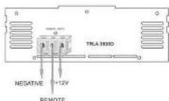
129=Contract the proper gauge power with 10V/10W/45mm-8+/-/litterwise, HMI/HTO
3
10
TROUBLE SHOOTING GUIDE
This section provides you with a categor of amplifier symptoms and their probable causes and solutions. Before you consult this listing, make sure the vehicle's electrical system in working properly by verifying that other electrical items (e.g. headlights, windows, etc.) still function correctly.
| SYMPTOM | PROBABLE CARGE | SOLUTION |
| No Audio | Low or N, C RemoteTurn-on connectionsBlown FusePower turns not connected | Check remove turn-on voltage atamp and head unitReplace with new test block fuseCheck boot platform to open the powerCheck ground and batteryinst systems |
| Blown on sound speakerconnected | Use VDM or DNA to measure speakersid importance; check speaker wiringconnections | |
| Discorded Audio | Input sensitivity not use;propertyor damaged speaker covers | See adjustment procedure and checkeach step;tracept each speaker for damageand repair or retraction associatedcomponent |
| Low turn-on voltage | Refer to head unit owner's manual | |
| Audio Level Low | Multi circuit on headunit on m. | Check electrical system for lowvoltage;Check ground connection |
| Audio Locks | Speaker wired with wrongpriority; causingconcealization of basccumferences | Check poorly of wrong fromamplifiers to switch speaker as defined bythe system designCheck battery voltage at amplifierduring operation |
| External FuseSlowing | Internal carding or shortcircuit | Refer to electrical installation andcheck electrical installation |
| Writing noiseon audio withenging running | Amplifier is pickingup along alternator noise | not all an in-line noise filter on therhead unit's power line. Checkadlers using matching holes or voltageregulator for proper operation. Checkag voltages, battery voltage, andRCA scales. |
| Listening noise onaudo withenging running | Amplifier is picking upodulated square noise | Check RCA audio audio; install anin-line filter on the head's power line. Check spark plugs, etc. |
8
ADJUSTMENTS
-
But to the "H.P.F" position when the amplifier is used to drive a wireless redranga system. The frequency below the crossover point will be attenuated at 12dB/active. Permits adjustment of the crossover frequency, by rotating the knob to select any frequency between 60Hz to 1.2KHz as the crossover point.
-
Set to the "L.P.F" position when the amplifier is used to drive a subwoven. The frequencies above the crossover point will be attenuated at 120bitcave. Points adjustment of the crossover frequency, by rotating the knot to select any frequency between 50Hz to 250Hz as the crossover point.
-
Set to the "OFF" position when the amplifier will be used for driving full-range speakers. The full frequency band width (20Hz\~25kHz) will be output to the speakers without high or low frequency attenuation.
-
Level adjustment: The sensitivity adjustment is to allow the amplifier to work with many different brands of head units. In low input signal to vary between 350 millips to 5 volt from the head unit or other signal processor. Star by setting the sensitivity adjustment to the MIN (3 volts). Using a cassette or compact disc that you are familiar with turn on head unit, and using a device to address the voltage in the VAX (200 millips) using an affal head-squeeze driver. Stop turning on the driven all distortion and turn back just a slight. The target voltage is rising to near the maximum volume for the head unit. The pool is to keep the level control to the forward setting yet still have enough signal to drive the amplifier. This is done to prevent over driving the amplifier and to keep the power of the output. This important no over drive speakers (all point of classification) will choose permanent damage to speaker. Also, if the amplifier first is over driven, it could be damaged.
-
The "BASS" function can be selected to increase low frequency response output, or decrease frequency response output. The "BASS" function will be working only. OFF or "L.P.F" position.
• The BASS is adjustable from 0–12 dB boost at 50Hz.
7
1 CHANNEL MONO BLOCK CLASS D AMPLIFIER CONNECTION
Install the fuse holder that is less than 2.5 meters from the battery. Remember the fuse is to protect the safety of the car in size of a short. Connect fuse better to battery but do not install fuse at this time.
This amplifier can operate in one, two or three channel modes. The minimum impedance for single channel (bridging mode) operation is 4 or 6 ohms. In channel power is related to stereo and mode at the same time. Maximum impedance remains the same for three channel (from woodpower) system along as proper passive cross-towers are used. Connection and left speaker wire to corresponding output terminals of the amplifier. Be sure that the positive output terminal is connected to a speaker output terminal. The amplifier has the negative wire with the speaker output connection with the negative speaker terminals of the amplifier. Lowering any of these connections will result in the speaker corner moving out of phase which causes bond concentration. See Fig. 3 Speaker Output Connection
MONO CHANNEL SPEAKER WIRING DIAGRAM
TXP1.3500D/TXP1.6000D/TXP1.12000D/TXP1.18000D
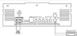
TXP1.3500D/TXP1.6000D/TXP1.12000D/TXP1.18000D
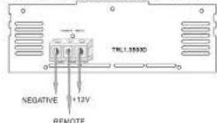
d
2CHANNEL AMPLIFIER WIRING
TXP2 6500D
FRONT
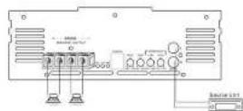
TXP2.6500D
REAR
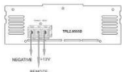
5
4CHANNEL AMPLIFIER WIRING
TXP4.3500D
ECONT
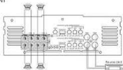
TXP4.3500D
REAR
6
- Congratulations on your Purchase
- Features
- Precautions: Read First!
- SPECIFICATION
- TXP1.12000D
- TXP1.18000D
- TXP2.65000
- TXP4.3500D
- TXP1.60000
- INSTALLATION & CONNECTIONS
- MOUNTING
- INPUT CONNECTIONS
- POWER CONNECTIONS
- TROUBLE SHOOTING GUIDE
- ADJUSTMENTS
- CHANNEL MONO BLOCK CLASS D AMPLIFIER CONNECTION
- MONO CHANNEL SPEAKER WIRING DIAGRAM
- 2CHANNEL AMPLIFIER WIRING
- 4CHANNEL AMPLIFIER WIRING
Brand : Soundstream
Model : TXP4.3500D
Category : Receiver