
AGITUM520 - Range hood Tisira - Free user manual and instructions
Find the device manual for free AGITUM520 Tisira in PDF.


| Product Type | Range Hood |
| Brand | Tisira |
| Model | AGITUM520 |
| Width | 52 cm |
| Depth | 50 cm |
| Height | 60 cm (adjustable) |
| Weight | 15 kg |
| Power Supply | 220-240 V ~ 50 Hz |
| Max Airflow | 620 m³/h |
| Noise Level | 55 dB (max speed) |
| Number of Speeds | 3 |
| Lighting | LED (2 x 3 W) |
| Filter Type | Aluminum grease filter (dishwasher safe) |
| Control Type | Electronic push buttons |
| Exhaust Diameter | 150 mm |
| Energy Class | A |
| Annual Energy Consumption | 50 kWh |
| Grease Filter Efficiency | Class B |
| Airflow Efficiency | Class A |
| Noise Class | C |
| Installation Type | Wall-mounted (chimney) |
| Material | Stainless steel & tempered glass |
| Maintenance | Clean grease filter monthly; replace activated carbon filter every 3-6 months |
| Safety Features | Overheat protection, auto shut-off (timer optional) |
| Warranty | 2 years |
Frequently Asked Questions - AGITUM520 Tisira
User questions about AGITUM520 Tisira
0 question about this device. Answer the ones you know or ask your own.
Ask a new question about this device
Download the instructions for your Range hood in PDF format for free! Find your manual AGITUM520 - Tisira and take your electronic device back in hand. On this page are published all the documents necessary for the use of your device. AGITUM520 by Tisira.
USER MANUAL AGITUM520 Tisira
520,700,850 //UNDERMOUNTHOOD
AGITUM520 | AGITUM700 | AGITUM850
IMPORTANT // Please ensure that you read through this user manual prior to installation and use. This manual contains important information to ensure optimal performance and keep you safe. Please retain your proof of purchase, as this will be required in the event that you require warranty service. Remember to retain this manual for future reference.
HELLO
CONGRATULATIONS ON THE SELECTION OF THIS RANGEHOOD. OUR APPLIANCES HAVE BEEN SPECIFICALLY DESIGNED FOR AUSTRALIAN AND NEW ZEALAND KITCHENS.
Please read through this user manual carefully as it contains information that will ensure that your appliance is installed correctly, important operating & care instructions and also some advice of what you need to do if this appliance is not performing as intended.
CONTENTS
HELLO 2
CONTENTS 3
WARNING & SAFETY INFORMATION 4
INSTALLATION & DUCTING 5
OPERATING INSTRUCTIONS 9
MAINTAINING YOUR RANGEHOOD 10
ELECTRICAL WIRING 12
PROOF OF PURCHASE 13
NOTES 14
IMAGES 16
CONTACT DETAILS 18
WARNING & SAFETY INFORMATION
This appliance is not intended for use by persons (including children) with reduced physical, sensory or mental capabilities, or lack of experience and knowledge, unless they have been given supervision or instruction concerning use of the appliance by a person responsible for their safety.
Young children should be supervised to ensure that they do not play with the appliance.
There shall be adequate ventilation of the room when the rangehood is used at the same time as appliances burning gas or other fuels.
- You must read the details concerning the method and frequency of cleaning.
There is a fire risk if cleaning is not carried out in accordance with the instructions.
Do not flambé under the rangehood.
Exhaust air must not be discharged into an existing flue which is used for exhausting fumes from appliances burning gas or other fuels.
The minimum distance between the hob surface and the lowest part of the rangehood is 600mm. This distance shall be at least 650mm, if the rangehood is installed over a gas hob. If the instructions for the gas hob specify a greater distance, this has to be taken into account.
Attention should be given to ensure that any applicable regulations concerning the discharge of exhaust air is fulfilled.
If the supply cord of this equipment is damaged, it must only be replaced by the manufacturer or its service agent or a similarly qualified person in order to avoid a hazard.
This appliance has been designed for indoor domestic use only.
Do not remove or inspect the filters whilst the hood is in operation.
INSTALLATION & DUCTING
AGITUM

INSTALLATION & DUCTING
IMPORTANT Before handling the rangehood during installation, it is recommended that you remove the filter to prevent damage.
Fig 1.2 illustrates the minimum height from the hob surface to the underside of the rangehood.
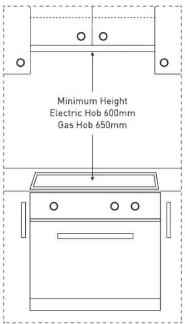
FIG 1.2
Electric hob - 600mm
Gas hob - 650mm
NOTICE: IF THE INSTRUCTIONS FOR THE GAS HOB SPECIFY A GREATER DISTANCE, THIS HAS TO BE OBSERVED. ANY INSTALLATION ABOVE 750MM WILL COMPROMISE PERFORMANCE.
INSTALLATION & DUCTING

natural_image
Pure mechanical diagram showing a lever and shaft assembly without any text, numbers, or symbolsTOP DUCTING SIDE DUCTING

natural_image
Pure technical line drawing of a mechanical assembly without any text, numbers, or symbols
natural_image
Pure architectural line drawing of a roof structure without any text, numbers, or symbolsRE-CIRCULATING
(Carbon filter required)
DUCTED OPTION
NOTICE // ALL DUCTING MATERIAL MUST BE COMPLIANT WITH THE LOCAL LAWS IN FORCE.
INSTALLATION
Before installing the appliance, make sure that none of the parts is damaged in any way. In case of damaged parts, contact your retailer and do not proceed with installation. Read all of the following instructions with care before installing the appliance.
Before installing the appliance, remove the metal grase filter. It can be removed by pushing its special handle toward the back-side of the cooker hood and turning the filter downwards so to unfasten it from its slot (Fig.1).
To install the appliance please respect the follow instructions.
The appliance must be install by competent authorities. In order to do not damage the electronic parts of the appliance please do not use added screws.
WARNING // Do not penetrate any screws into the rangehood as this may result in electrical hazards. Failure to install the screws or fixing device in accordance with these instructions may result in electrical hazards.
INSTALLATION & DUCTING
Essential precautions to respect before in- stalling the appliance are the following:
1) Prepare the power supply.
2) Prepare a hole for the exhaust of the air both in the filtering and in the exhau sting version.
Use an exhausting pipe whose maximum length does not exceed 5 meters.
3) Do not use screws to fix the outlet pipe to the cooker hoods.
4) Limit the no. of elbows in the piping, since each elbow reduces the aspiration efficiency of 1 linear meter. (Ex.: if you use no. 2 x90° elbows, the length of pi ping I must not exceed 3 meters)
5) Avoid abrupt direction changes.
6) Use a 150 mm or 200 mm constant dia meter pipe for the whole length.
7) Use piping approved by standards in force.
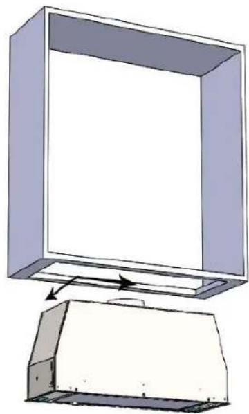
8) To have made a cut-out on the bottom of the cabinet which is suitable to hold the appliance in position (Fig. 2).
AGITUM 520 505mmX270mm
AGITUM 700 685mmX270mm
AGITUM 850 835mmX270mm
9) Right now, after drilling the kitchen cabinet please follow carefully the instructions also above, calibrate the fixing spring depending on the depth of cabinet. (Fig. 3).
10) At this point, insert the range hood inside the kitchen cabinet until the fixed springs will be hooked into.
11) Fix the range hood to the cabinet, in the left and right sides, using by the screws equipped (Fig. 4).
12) At the end, place the grease filters that were removed before.
Warning!
Before connecting the flexible exhausting pipe to the motor, make sure the stop valve, which is on the air outlet of the motor, can swing.
Exausting version
Connect the flange to the exhausting hole with an appropriate pipe. Connect the appliance with the electrical mains through the supply cord.
Filtering version
Connect the flange with a pipe suitable to convey the air to the top of the cabinet. Connect the appliance with the electrical mains through the supply cord.
OPERATING INSTRUCTIONS

A

B

C

D

E
Model: Agitum
A: Motor switch on/off (1st rate level)
B: 2nd rate level switch
C: 3rd rate level switch
D: 4th rate level switch
E: Light switch on/off
The products are endowed with an electronic device which allows the automatic switching off after 4 hours working from the last operation.
MAINTAINING YOUR RANGEHOOD
GENERAL MAINTENANCE
Ensure that the power to the unit is switched off prior to cleaning the unit. Surface should only be cleaned with warm soapy water and a soft non-abrasive cloth. In coastal environments and humid areas more frequent cleaning is required to maintain the finish.
Particular care is due to the grease filter. It can be removed by pushing its special handle toward the back-side of the cooker hood and turning the filter downwards so to unfasten it from its slot (Fig.1).
To insert the filter just perform the opposite operation. After 30 hours working (model), the push button control panel will signal the saturation of the grease filter by lighting all the buttons. Press the 0/1 button for 2 seconds to reset when the motor is off. The grease filter needs cleaning by regular handwashing or in dishwashers every two months at least or depending on its use.
To clean the appliance itself tepid water and neutral detergent are recommended, while abrasive products should be avoided. For steel appliances specialized detergents are recommended (please follow the instructions indicated o the product itself to obtain the desired results).
Warning! To take down the appliance from the cabinet, remove the definitive fixing screws (Fig. 4) using a screw-driver, get off the grease filters (Pic. 1).
Act on the small handle of the springs, which are inside the built-in unit, with the necessary strength to unhook the appliance from the cabinet.
If the supply cord is damaged, it must be replaced by the manufacturer or its sevice agent or a similarly qualified person in order to avoid a hazard.
MAINTAINING
YOUR
RANGEHOOD
LAMPS
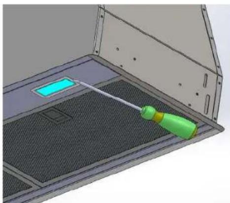
Before to replace the led lamp switch off the appliance then by using appropriate tools remove the led lamp from its slot (Fig. 5).
Take out the led lamp from its connector and replace with similar characteristics.
To find the correct led lamp please check on the replacement part list.
If the supply cord is damaged, it must be replaced the manufacturer or its service agent or a similarly qualified person in order to avoid a hazard.
MODEL
AGITUM 520
AGITUM 700
AGITUM 850
LAMP TYPE
2X SPOT LED REVO 2.5W
2X SPOT LED REVO 2.5W
2X SPOT LED REVO 2.5W
ELECTRICAL WIRING

PROOF OF PURCHASE
ATTACH YOUR PROOF OF PURCHASE FOR FUTURE REFERENCE
NOTES
NOTES
IMAGES

natural_image
3D architectural rendering of a modern building interior with ventilation grilles and a central skylight (no text or symbols visible)Fig. 1
natural_image
Diagram of a computer monitor with an open lid and a base cover, showing no text or symbols.Fig.2
AGITUM 520: 505mm x 270mm
AGITUM 700: 685mm x 270mm
AGITUM 850: 835mm x 270mm

natural_image
Diagram of a mechanical assembly with two parts, one marked with a red arrow and the other with a black arrow, enclosed in a circle (no text or symbols)Fig.3

natural_image
3D technical diagram of a mechanical device with control panel and airflow indicators (no text or symbols)Fig.4
IMAGES
natural_image
3D CAD rendering of a mechanical component with a green tool inserted into a mesh chamber (no text or symbols visible)Fig.5
CONTACT DETAILS
AUSTRALIA
ARISIT PTY LIMITED
40-44 Mark Anthony Drive
Dandenong South, VIC 3175
Australia
Ph 1300 815 589
FX (03) 9768 0838
consumer.care@arisit.com
NEW ZEALAND
ARISIT PTY LIMITED
PO Box 68-140
Newton, Auckland
1145
New Zealand
Ph (09) 306 1020
FX (09) 302 0077
sales@aristonappliances.co.nz
ARISTON IS COMMITTED TO ONGOING RESEARCH AND DEVELOPMENT. EVERY EFFORT HAS BEEN MADE TO ENSURE ALL INFORMATION IN THIS USER MANUAL IS CORRECT AT TIME OF COING TO PRINT.
DIMENSIONS SHOULD BE USED AS A REFERENCE ONLY AND ACTUAL DIMENSIONS SHOULD BE TAKEN FROM THE PHYSICAL PRODUCT ONLY.
MANUFACTURER RESERVES THE RIGHT TO CHANGE SPECIFICATIONS WITHOUT NOTICE
- HELLO
- CONGRATULATIONS ON THE SELECTION OF THIS RANGEHOOD. OUR APPLIANCES HAVE BEEN SPECIFICALLY DESIGNED FOR AUSTRALIAN AND NEW ZEALAND KITCHENS.
- CONTENTS
- HELLO 2
- CONTENTS 3
- WARNING & SAFETY INFORMATION 4
- INSTALLATION & DUCTING 5
- OPERATING INSTRUCTIONS 9
- MAINTAINING YOUR RANGEHOOD 10
- ELECTRICAL WIRING 12
- PROOF OF PURCHASE 13
- NOTES 14
- IMAGES 16
- CONTACT DETAILS 18
- WARNING & SAFETY INFORMATION
- INSTALLATION & DUCTING
- DUCTED OPTION
- INSTALLATION
- Warning!
- Exausting version
- Filtering version
- OPERATING INSTRUCTIONS
- Model: Agitum
- MAINTAINING YOUR RANGEHOOD
- GENERAL MAINTENANCE
- MAINTAINING
- YOUR
- RANGEHOOD
- LAMPS
- MODEL
- LAMP TYPE
- ELECTRICAL WIRING
- PROOF OF PURCHASE
- NOTES
- IMAGES
- CONTACT DETAILS
- AUSTRALIA
- NEW ZEALAND
Brand : Tisira
Model : AGITUM520
Category : Range hood