
PR15D - Measurement Seaward - Free user manual and instructions
Find the device manual for free PR15D Seaward in PDF.


| Product Type | Portable Appliance Tester (PAT) |
| Brand | Seaward |
| Model | PR15D |
| Category | Measurement |
| Dimensions (approx.) | 200 x 100 x 50 mm |
| Weight (approx.) | 0.5 kg |
| Power Supply | Mains powered (230V AC) or internal rechargeable battery |
| Display | Backlit LCD |
| Insulation Resistance Test | Up to 1000 V, resolution 0.01 MΩ |
| Earth Bond Test | Up to 25 A, resolution 0.01 Ω |
| Leakage Current Test | 0 to 20 mA |
| Protection Class | IP40 |
| Safety Standards | IEC 61010-1, EN 61557 |
| Memory Storage | Up to 1000 test results |
| Connectivity | USB for data transfer |
| Operating Temperature | 0°C to 40°C |
| Storage Temperature | -10°C to 60°C |
| Accessories Included | Test leads, probe, mains cord, carry case |
| Maintenance | Clean with a dry cloth; recalibrate annually |
| Reparability | Serviceable by authorized centers; replaceable fuses and battery |
Frequently Asked Questions - PR15D Seaward
User questions about PR15D Seaward
0 question about this device. Answer the ones you know or ask your own.
Ask a new question about this device
Download the instructions for your Measurement in PDF format for free! Find your manual PR15D - Seaward and take your electronic device back in hand. On this page are published all the documents necessary for the use of your device. PR15D by Seaward.
USER MANUAL PR15D Seaward
PR Digital Range of Phase Comparison Equipment
Operating Instructions

SEAWARD
Bracken Hill, South West Industrial Estate, Peterlee, Co. Durham SR8 2SW. England. Tel: +44 (0)191 586 3511 Fax: +44 (0)191 586 0227 www.seaward.com sales@seaward.com service@seaward.com
Limited Warranty & Limitation of Liability
SEAWARD Electronic Limited guarantees this product to be free from defects in material and workmanship under normal use and service for a period of 1 year. The period of warranty will be effective at the day of delivery.
© Copyright 2014
All rights reserved. Nothing from this edition may be multiplied, or made public in any form or manner, either electronically, mechanically, by photocopying, recording, or in any manner, without prior written consent from SEAWARD Electronic Limited. This also applies to accompanying drawings and diagrams.
Due to a policy of continuous development SEAWARD Electronic Limited reserves the right to alter the equipment specification and description outlined in this publication without prior notice and no part of this publication shall be deemed to be part of any contract for the equipment unless specifically referred to as an inclusion within such contract.
Disposal of Old Product

natural_image
Symbol of a trash bin crossed out by two diagonal lines (no text or numbers present)
This product has been designed and manufactured with high quality materials and components that can be recycled and reused.
When the crossed out wheelie bin symbol is attached to a product it means the product is covered by the European Directive 2012/19/EU.
Please familiarise yourself with the appropriate local separate collection system for electrical and electronic products.
Please dispose of this product according to local regulations. Do not dispose of this product along with normal waste material. The correct disposal of this product will help prevent potential negative consequences for the environment and human health.
PR Digital Range Phase Comparison Equipment
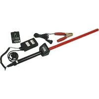
The Seaward PR Digital Range of Phase Comparison Equipment provides a means of confirming the presence of voltage on electrical circuits from 1 to 33KV.
The PR Digital Range of Phase Comparison Equipment complies with the UK Electricity Council Engineering Recommendation G9.
Contents
- User Notes
- Safety Notes
- Standard Accessories
- Description
- Electrical Specifications
- Operation
- Battery Charging
- Extension & Bent Rods
- Proving Unit
- Maintenance
- Cleaning
1.0 User Notes
These operating instructions are intended for the use of competent personnel.
The PR Digital Range of Phase Comparison Equipment has been designed to make measurements in a dry environment.
The following symbols are used in these operating instructions and on the PR Digital Range of Phase Comparison Equipment.

Warning of electrical danger!
Indicates instructions must be followed to avoid danger to persons.

Important, follow the documentation!
This symbol indicates that the operating instructions must be adhered to in order to avoid danger.
2.0 Safety Notes
To ensure safe operation of the unit, all notes and warnings in these instructions must be observed at all times.
This instrument should only be used by competent, suitably trained personnel, wearing appropriate PPE, after due consideration of any hazard involved.

Never hold the instrument between the hand guard / digital display housing and the contact electrode.

The Phase Comparison Equipment and all associated cables and leads must be checked for signs of damage before the equipment is operated.

Always ensure the earth cable is securely attached to the equipment and that the clip is connected to earth during tests.

Always proof test before and after use.

Always ensure equipment is properly rated for use at the voltage in the system under test.

Never allow any part of the instrument below the limit mark to make contact with a live high voltage conductor.
The limit mark is a band, approx. 20mm in width, printed on the body of the detector and extensions rods.
Where safe operation of the equipment is no longer possible it should be immediately shutdown and secured to prevent accidental operation.
It must be assumed that safe operation is not longer possible:
- if the equipment or the cable show visible signs of damage, or
- the instrument does not function, or
- after long periods of storage under adverse environmental conditions.
3.0 Accessories
3.1 Standard Accessories
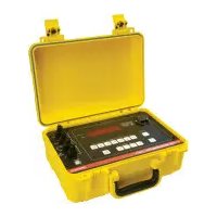
• PH3 proving unit (Part No 112A913)
• PSU100 battery charger (Part No 124A912)
• 1.5m Straight extension rod x 2 (Part No 141A901)
• Earth Lead 3m (Part No 109A019)
- Carry Case (Part No 71G014)
3.2 Optional Accessories
- 90 degree bent end extension rod (Part No 141A900)
- 120 degree bent end extension rod (Part No 141A912)
4.0 Description
The PR Instrument Range provides a means of determining both AC and DC voltage on electrical circuits (when used as a potential indicator) or when connected to a secondary element enables phase angle comparison and indication of phase angle voltage at the point of paralleling two circuits.
The equipment has the following features:-
4.1 The units consist of an element manufactured from a high quality PVC tube. The tube supports and isolates a chain of high value internal resistors.
4.2 The total encapsulation of the load element prevents any internal tracking or leakage.
4.3 A handguard in the form of a digital display housing on the handle section of the unit prevents the operators hands from straying towards the high voltage ends of the potential indicator.
4.4 An additional phasing rod (secondary element) manufactured from the same high quality PVC as indicated in section 4.1 and supports / isolates another chain of high value resistors.
4.5 The phasing rod is also manufactured with a handguard and provides total encapsulation of the load elements.
4.6 The digital voltage display is incorporated into the handguard housing.
4.7 An external domed contact electrode ensures a positive contact with any terminal required to be tested.
4.8 An insulated earth cable is connected to the potential indicator section of the equipment through the handle. The earth cable is detachable. This earth cable is fitted with a suitable clamp that allows the operator to reference the potential indicator to a suitable earth.
4.9 Labels present on the equipment and accessories are there to ensure safe use of the equipment.
5.0 Electrical Specifications
| PR15D PR33D | ||
| Maximum System voltage | 15kV | 33kV |
| Maximum Voltage to earth | 8.6kV | 19kV |
| 0.00kV-8.6kVMeasuring Range 0.0kV-19.0kV | ||
| 10VResolution 100V | ||
| AC/DCSensitivity AC/DC | ||
| Circuit current (IEC 61234-2) | 0.5mA nominal @8.6kV | 0.9mA nominal @19kV |
| Dielectric leakage current (IEC 61234-2) | 7uA nominal @ 18kV | 23uA nominal @ 40kV |
| 600Length (mm) 600 | ||
| 27Diameter (mm) 27 | ||
| 235Handle length (mm) 235 | ||
| Hand guard height (mm) | 23.5 | 23.5 |
| Contact Electrode Type | Domed | Domed |
Extension Rods
| Straight | 90° | 120° | |
| Maximum System voltage | 33kV | 15kV 33kV | |
| Dielectric leakage current | 140uA nominal @ 40kV | 50uA nominal @ 18kV | 130uA nominal @ 40kV |
| Length (mm) | 1100 | 780 | 780 |
| Diameter (mm) | 27 | 27 | 27 |
| Contact Electrode Type | “V” form | Domed | Domed |
6.0 Operation
6.1 Potential Indicator/Voltage measurement
6.1.1 The insulated earth cable, 3m in length, is connected by means of a plug and socket arrangement to the bottom of the handheld section of the potential indicator.

6.1.2 On connection of the insulated earth cable to the bottom of the handheld section the digital display is automatically powered up and zeroed ready for operation.

Always screw up the plug and socket securely.
6.1.3 Before use the digital unit must be proof tested on a suitable proving unit such as the supplied Seaward PH3 proving unit. Refer to section 9.0
6.1.4 The earth clamp attached to the free end of the insulated earth cable must be attached to a suitable earth point i.e. an earthed strip of frame or an earth electrode.
6.1.5 The contact electrode of the digital unit should be positioned such as to make contact with the voltage source to be measured. The digital display will indicate the value of the voltage present.

Never hold the potential indicator between the hand guard and the exposed metal head.
6.1.6 The potential indicator must be applied in turn to each phase of the system under test.
6.1.7 After use the potential indicator must be proof tested on a suitable proving unit such as the supplied Seaward PH3 proving unit. Refer to section 9.0
6.1.8 Once testing is complete unclip the earth clamp from the reference earth point. Disconnect the earth cable from the bottom of the potential indicator and replace the protective cap over the plug of the potential indicator.

Always ensure the earth cable is disconnected from the potential indicator when not in use to prevent the battery from being fully discharged.
6.2 Phase Detection
6.2.1 The insulated earth cable, 2m in length, along with the 600mm linking cable permanently connected to the phasing rod are connected by means of a plug and socket arrangement to the bottom of the handheld section of the potential indicator.

6.2.2 On connection of the insulated earth cable to the bottom of the handheld section the digital display is automatically powered up and zeroed ready for operation.

Always screw up the plug and socket securely.
6.2.3 The earth clamp attached to the free end of the insulated earth cable needs to be attached to a suitable earth point i.e. an earthed strip of frame or an earth electrode.
6.2.4 Before use both the digital unit and phasing rod must be proof tested on a suitable proving unit such as the supplied Seaward PH3 proving unit. Refer to section 9.0
6.2.5 The contact electrode digital unit should be positioned such as to make contact with a conductor or terminal of the first circuit. The digital unit will display the value of any voltage present at the contact electrode.
6.2.6 The contact electrode of the phasing rod is then, applied, in turn, to each phase conductor or terminal on the second circuit.

Never hold the potential indicator between the hand guard and the exposed contact electrode.
6.2.6 The display will now indicate the potential difference between the two contact electrodes i.e. a reading proportional to phase angle difference and the rated voltage of the system when the digital unit and the phasing rod are between different phases. When the digital unit and phasing rod are connected to the same phase, the display will indicate a reading <900V depending on the capacitance to earth of the primary and secondary elements.
6.2.7 After use both the digital unit and phasing rod must be proof tested on a suitable proving unit such as the supplied Seaward PH3 proving unit. Refer to section 9.0
6.2.8 Once testing is complete unclip the earth clamp from the reference earth point. Disconnect the earth and linking cable from the bottom of the potential indicator element of the phase comparison equipment and replace the protective cap over the plug of the potential indicator

Always ensure the earth and link cable are disconnected from the potential indicator when not in use to prevent the battery from being fully discharged.
7.0 Battery Charging

A “BAT” sign on the digital display of the potential indicator unit of the Phase Comparison Equipment denotes that the battery requires charging.

During prolonged storage periods the battery will discharge. In order to increase the battery life the instrument should be charged periodically.
7.1 Remove the protective cap from the connector on the bottom of the hand held section of the digital unit.
7.2 Insert the 6 pin socket fl ying lead from the PSU100 battery charger – Seaward Part 124A912 into the connector and fi rmly screw into place. Connect the mains lead from the charger to a 240VAC 50Hz supply and switch on.
7.3 When mains power is applied to the battery charger, one LED is continuously illuminated and a second LED will flash approximately every 5 seconds to indicate the battery is being charged.
7.4 After approximately 14 hours the continuously illuminated LED will be extinguished indicating charging is completed.
7.5 On completion of the charging cycle, disconnect the battery charger supply from mains, disconnect the 6 pin socket from the base of the potential indicator and replace the protective cap over the plug.

Do not use the potential indicator on a high voltage circuit while the battery is on charge.
8.0 Extension & Bent End Rods
8.1 Attachment
8.1.1 Loosen but do not fully remove the knurled head on the extension rod.
8.1.2 If the equipment is fitted with removable contact electrodes, remove the domed head from the digital unit and/or phasing rod. Store the domed heads in a safe location.
8.1.3 Screw the extension rod onto either the digital unit or phasing rod and ensure that the two elements are fully mated without over tightening.
8.1.4 Tighten the knurled head at the end of the extension rod to secure the two elements together.

At no time after the extension unit has been fully tightened to either the digital unit or phasing rod should any attempt be made to separate the two elements until all testing (including proof testing) has been completed.
8.1.5 To remove an extension rod from either the digital unit or phasing rod, loosen the knurled head at the end of the extension rod before unscrewing the extension rod from either the digital unit or the phasing rod.
8.1.6 If the equipment is fitted with removable contact electrodes, replace the domed head on the digital unit and / or phasing rod and tighten the knurled head on the extension rod when complete.
8.2 Operation of Extension and Bent end Rods on HV Systems
8.2.1 Extension rods can be used on a HV system with either the digital unit or phasing rod. Extension rods cannot be used without first being connected to either a digital unit or phasing rod.
8.2.2 The digital unit and phasing rod can be used on a HV system up to the designated voltage levels without an extension rod.

Always fi t the forked head to extension rods when testing Overhead Lines.
8.3 Proof Testing
8.3.1 Extension rods must be proof tested using the Seaward PH3 proving unit, both before and after use. For more detailed information see section 9.
9.0 Proof Testing
9.1 Features of a PH3 Proving Unit
9.1.1 The terminations on the unit comprise of a knurled earth terminal at one end and a small metal probe on top of the unit. The small metal probe on top of the unit is manufactured to accommodate a domed contact electrode.
9.1.2 A push switch operates the test voltage output.
9.1.3 The unit requires an alkaline PP3 type battery, also identified as a MN1604 and with the I identifi er 6LR61.
9.1.4 Ensure that the red LED on the proving unit operates before and after the unit has been used.

Warning – Do not touch the earth terminal and the brass tip on the proving unit simultaneously. When the push button is pressed a high voltage is generated between these points.
9.2 Proof testing as a potential indicator
9.2.1 Connect the insulated earth cable, 3m in length, by means of a plug and socket arrangement to the bottom of the handheld section of the digital unit.
9.2.2 On connection of the insulated earth cable to the bottom of the handheld section the digital display is automatically powered up and zeroed ready for operation.
9.2.3 The earth clamp attached to the free end of the insulated earth cable should be attached to the knurled earth terminal on the proving unit.
9.2.4 Push the digital unit contact electrode on to the brass contact on the PH3 proving unit.

9.2.5 Press the pushbutton on the proving unit. The display on the digital potential indicator will give a reading between 1000V and 1500V depending on the condition of the battery in the PH3.

Warning – Do not touch the earth terminal and the brass tip on the proving unit simultaneously. When the push button is pressed a high voltage is generated between these points.
9.2.6 On completion of the proving test, release the push button.
9.3 Proof testing as a phase comparator
9.3.1 Connect the insulated earth cable, 2m in length, along with the 600mm linking cable permanently connected to the phasing rod and connected by means of a plug and socket arrangement to the bottom of the handheld section of the potential indicator.
9.3.2 On connection of the insulated earth cable to the bottom of the handheld section the digital display is automatically powered up and zeroed ready for operation.
9.3.3 Push the digital unit contact electrode on to the brass contact on the PH3 proving unit.

9.3.4 Press the pushbutton on the proving unit. The display on the digital potential indicator will give a reading between 1000V and 1500V depending on the condition of the battery in the PH3.
9.3.5 Push the digital unit contact electrode on to the brass contact on the PH3 proving unit.

9.3.6 Press the pushbutton on the proving unit. The display on the digital potential indicator will give a reading between 1000V and 1500V depending on the condition of the battery in the PH3.

Warning – If the readings between digital unit and phasing rod are >20% then DO NOT USE the phase comparison equipment.
9.3.7 On completion of the proving test, release the push button, disconnect the earth clamp from the knurled nut and remove the proving unit brass tip from the exposed metal head of the phasing rod.
10.0 Maintenance
10.1 The PR digital range of phase comparison equipment is extremely robust and should always be kept free from dust or any loose carbon particles.
10.2 Ensure the PR digital range of phase comparison equipment is kept dry with no surface moisture on either the body or housing / hand guard of the indicator or phasing rod.
10.3 The body of both the potential indicator and phasing rod should be regularly inspected to ensure no deep scratches or physical damage.
10.4 Ensure the insulation of the earth and linking cable is fully intact and that no sharp creases have occurred in the cable.
10.5 It is recommended that the phase comparison equipment should be regularly proof tested at scheduled maintenance intervals as well as before and after testing on energised circuits.
10.6 If any of the above conditions have been observed then the phase comparison equipment must be appropriately secured to prevent any further use.
10.7 Ensure that the equipment is stored dry with no surface moisture on the body or housing / hand guard of the indicator or phasing rod.
10.8 Always transport the equipment in the carrying case provided. Always handle with care.
10.9 There are no user serviceable parts on the equipment.

Always ensure the earth cable is disconnected from the potential indicator when not in use, to prevent the battery from being fully discharged.
11.0 Cleaning
11.1 Clean the external case of the phase comparison equipment with a clean dry cloth.
11.2 Avoid using solvents and abrasive scouring agents to clean the external case of phase comparison equipment.
11.3 Check the battery contacts and mounting compartment are free of electrolytic contamination.
11.4 Any contamination of the battery contacts or compartment should be cleaned with a dry cloth.


- PR Digital Range of Phase Comparison Equipment
- SEAWARD
- Limited Warranty & Limitation of Liability
- Disposal of Old Product
- PR Digital Range Phase Comparison Equipment
- Contents
- The PR Digital Range of Phase Comparison Equipment has been designed to make measurements in a dry environment.
- Safety Notes
- Accessories
- Standard Accessories
- Optional Accessories
- Description
- Operation
- Potential Indicator/Voltage measurement
- Always screw up the plug and socket securely.
- Never hold the potential indicator between the hand guard and the exposed metal head.
- Phase Detection
- Never hold the potential indicator between the hand guard and the exposed contact electrode.
- Always ensure the earth and link cable are disconnected from the potential indicator when not in use to prevent the battery from being fully discharged.
- Battery Charging
- Extension & Bent End Rods
- Attachment
- Operation of Extension and Bent end Rods on HV Systems
- Proof Testing
- Proof Testing
- Features of a PH3 Proving Unit
- Proof testing as a potential indicator
- Proof testing as a phase comparator
- Maintenance
- Cleaning
Brand : Seaward
Model : PR15D
Category : Measurement