
DO7e - Measurement Seaward - Free user manual and instructions
Find the device manual for free DO7e Seaward in PDF.

| Product Type | Digital Microhmmeter (Ohmmeter) |
| Brand | Seaward (Cropico) |
| Model | DO7e |
| Measurement Principle | True 4-terminal Kelvin method |
| Measurement Ranges | 600 Ω, 60 Ω, 6 Ω, 600 mΩ, 60 mΩ, 6 mΩ |
| Resolution | 100 mΩ (600 Ω) to 1 μΩ (6 mΩ) |
| Accuracy | ±(0.25% of reading + 0.05% of full scale) at 20°C ±5°C |
| Display | 4-digit LCD, 6000 counts, auto decimal point |
| Measurement Time | Approx. 0.5 seconds per reading |
| Polarity Selection | Positive (+), Negative (-), Average (AVE) to cancel thermal EMF |
| Power Supply | Mains 115V or 230V AC (selectable), 47-63 Hz; internal rechargeable sealed lead-acid battery |
| Power Consumption | < 20 VA |
| Dimensions (W x D x H) | 343 x 327 x 152 mm |
| Weight | 6.0 kg |
| Operating Temperature | 0°C to +40°C, max 80% RH |
| Storage Temperature | -20°C to +50°C |
| Safety Rating | CAT III < 50 V per BS EN:61010 |
| Protection | 6A HRC fuse for current terminals; gas discharge tube across C terminals |
| Auto Power Off | After 5 minutes of inactivity |
| Supplied Accessories | 1 set test leads, 1 mains cord, operating instructions |
| Maintenance | Clean with moist cloth; no aggressive solvents |
| Calibration | User calibration with passcode (default 9252) using internal standards or external resistor |
Frequently Asked Questions - DO7e Seaward
User questions about DO7e Seaward
0 question about this device. Answer the ones you know or ask your own.
Ask a new question about this device
Download the instructions for your Measurement in PDF format for free! Find your manual DO7e - Seaward and take your electronic device back in hand. On this page are published all the documents necessary for the use of your device. DO7e by Seaward.
USER MANUAL DO7e Seaward
Digital Microhmmeter Type D07e
Operating Instructions

CROPICO
Bracken Hill, South West Industrial Estate,
Peterlee, Co. Durham SR8 2SW. England.
Tel: +44 (0)191-586 3511 Fax: +44 (0)191-586 0227
www.cropico.co.uk
sales@cropico.co.uk
Limited Warranty & Limitation of Liability
CROPICO guarantees this product for a period of 1 year. The period of warranty will be effective at the day of delivery.
(c) Copyright 2013
All rights reserved. Nothing from this edition may be multiplied, or made public in any form or manner, either electronically, mechanically, by photocopying, recording, or in any manner, without prior written consent from CROPICO. This also applies to accompanying drawings and diagrams.
Due to a policy of continuous development CROPICO reserves the right to alter the equipment specification and description outlined in this publication without prior notice and no part of this publication shall be deemed to be part of any contract for the equipment unless specifically referred to as an inclusion within such contract.
Disposal of Old Product

natural_image
Symbol of a trash bin with crossed lines indicating no waste or restriction, and a solid black rectangle below (no text or symbols)This product has been designed and manufactured with high quality materials and components that can be recycled and reused.
When the crossed out wheelie bin symbol is attached to a product it means the product is covered by the European Directive 2012/19/EU.
Please familiarise yourself with the appropriate local separate collection system for electrical and electronic products.
Please dispose of this product according to local regulations. Do not dispose of this product along with normal waste material. The correct disposal of this product will help prevent potential negative consequences for the environment and human health.
Supplied Accessories: 3
- SAFETY 3
- INTRODUCTION 4
Display range 6000 .... 4
- MEASURING PRINCIPLE 4
- CASE DESIGN 4
- MAINTENANCE 4
- BATTERY CHARGING 5
BATTERIES 5
BATTERY REPLACEMENT 6
- TECHNICAL DATA 6
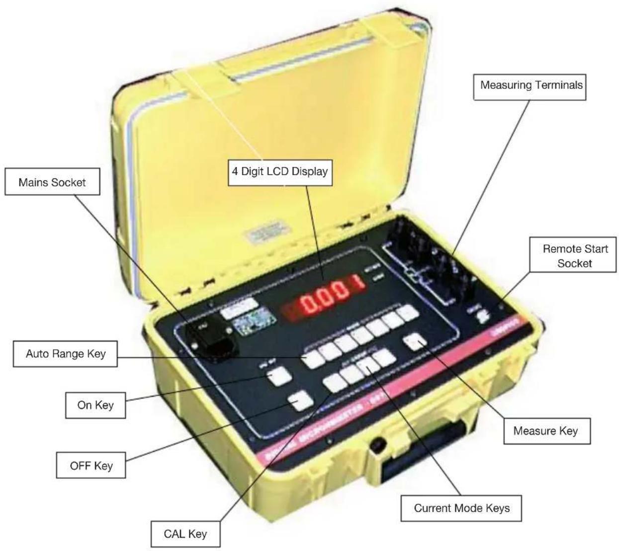
- DESCRIPTION OF CONTROLS 7
Range Selection: 8
Error & Status Lamps 8
- METHODS OF MEASUREMENT 8
- POWER UP 11
- MEASUREMENT 11
Current Mode 11
Over-Range 11
Low Battery 12
- Connections 12
- REMOTE 12
- PROTECTION 12
- CALIBRATION PROCESS 12
- EQUIPMENT REQUIRED 13
- PREPARATION 13
- CALIBRATION 13
- USING DISCRETE RESISTANCE STANDARDS 14
IMPORTANT NOTE
Instruments are delivered ready for immediate use; no extras are required.
Supplied Accessories:
1 Set of test leads
1 Mains cord
1 Operating Instructions (English)
When unpacked, inspect for physical damage and report any defects immediately in writing, retaining packaging materials for inspection. Before placing into service, ensure mains voltage is correct, instruments are normally supplied for 230V 50Hz. Other voltages may also be selected according to the chart in section 5, (Maintenance). Be sure to also change the fuse to the correct type.
1. SAFETY
This apparatus is designated Safety Class I as defined in the IEC Publication 1010-1 (Amend 1)
This apparatus has been designed and tested in accordance with IEC Publication 348, entitled “Safety Requirements for Electronic Measuring Apparatus”, and has been supplied in a safe condition. The present instruction manual contains some information and warnings, which must be followed by the user to ensure safe operation and to retain the apparatus in safe condition.
This instrument has been designed and tested to BS EN:61010 overvoltage category CAT III <50V
Before switching on the apparatus, make sure that it is set to the voltage of the power supply. The mains plug shall only be inserted in a socket outlet provided with protective earth contact. The protective action must not be negated by the use of an extension lead without a protective conductor.
WARNING!
Any interruption of the protective conductor inside or outside the apparatus, or disconnection of the protective earth terminal is likely to make the apparatus dangerous. Intentional interruption is prohibited.
When the apparatus is connected to its mains supply, terminals may be live, and the opening of covers or removal of parts (except those to which access can be gained by hand) is likely to expose live parts.
The apparatus must be disconnected from all voltage sources before it is opened for any adjustment, replacement, maintenance or repair.
Any adjustment, maintenance and repair of the opened apparatus under voltage shall be avoided as far as possible, and, if inevitable, shall be carried out only by a skilled person who is aware of the hazard involved.
Make sure that only fuses with the required current rating and of the specified type are used for replacement. The use of makeshift fuses, and the short-circuiting of fuse holders is prohibited.
Whenever it is likely that the protection has been impaired, the apparatus shall be made inoperative and be secured against any unintended operation and returned to our factory or Agent for rectifi cation.
Prior to connecting this instrument always ensure that the circuit under test is electrically isolated. Connecting this instrument to circuits that have not been isolated could lead to a hazard.
2. INTRODUCTION
The DO7e is an accurate bench/portable Digital Ohmmeter for the measurement of resistance in the range 1 to 600 . It offers you the four terminal resistance measurement method to eliminate the effect of lead resistance. The measured values are displayed on a 4-digit LED display; an overflow of the selected range is also indicated.
Display range 6000
Simple push-button or auto-range selection of the range required, ensures that the DO7e may be easily used by unskilled personnel. Error and status warnings are illuminated when appropriate. The utmost care has been taken to ensure that the ohmmeter will withstand an accidental mains voltage applied to the measuring terminals, but it is not recommended that voltage should be applied.
3. MEASURING PRINCIPLE
The measurement is true 4 terminal, using the Kelvin principle. A stable current is produced across the resistance to be measured via the C terminals, and the voltage drop across the Rx is measured at the P terminals. This potential drop is then compared against the voltage drop across internal standards. The ratio of these is then converted to the resistance value of Rx and displayed in ohms on the digital display. High accuracy and long term stability is achieved by using Specially selected components.
4. CASE DESIGN
The case is ruggedly constructed from an ABS/polycarbonate alloy, coloured safety yellow. A strong internal sub-frame ensures that the DO7e will withstand the harshest of environments. The front panel is a reverse printed polycarbonate overlay with clear and unambiguous text.
5. MAINTENANCE
Normally no maintenance is required other than cleaning with a moist cloth. Avoid aggressive detergents or solvents.
CAUTION: Before any maintenance, repair or exchange of parts or fuses, the instrument must be disconnected from the mains supply and all power sources. In the event of a fault occurring, the instrument should be returned to our factory or Agent. A mains fuse is fitted to the mains inlet socket on the front panel, and should be replaced if necessary.
CAUTION: Disconnect mains lead and all connecting leads, before removing fuse holder. Replace only with the correct fuse type, ie. according to the following chart.
| Line Voltage Selection | Range VAC 47-63Hz | Fuse (250V) IEC 127 5 x 20 mm |
| 120V | 104-132V | 250mA(T) |
| 230V | 209-264V | 125mA(T) |
| Maximum Input Power : 18VA | ||
The input circuits are protected by a 6 AMP fuse located in a holder on the main printed circuit board. Access is gained by removing the top cover. Only replace with the correct fuse type as below.
10A Am 550V rms HRC Ceramic Cartridge 10 x 38 mm
IEC 269-2-1 NFC63-210
6. BATTERY CHARGING
The DO7e has a built-in rechargeable sealed lead acid battery, which is fully charged when delivered. To ensure good service life from the battery, the DO7e incorporates a sophisticated battery management system. Low battery condition is indicated by a panel mounted LED.
The battery charger is built in and the instrument may be connected to 110/230 volts supply. The appropriate voltage setting must be selected on the inlet socket and the correct fuse inserted. The LINE LED will illuminate on the front panel to indicate when the mains supply is connected.
Charging is automatically controlled with built-in protection circuits eliminating the possibility of over-charging. The display will blank when the battery voltage is too low to sustain measurements, and the low battery indicator will illuminate. The battery will recharge in approximately six hours, and the DO7e lid should be open to allow for maximum ventilation.
IMPORTANT: Always connect instrument to mains supply after use and top up battery. Instruments should be stored with batteries fully charged, and when stored for long periods the batteries should be recharged each month.
Should the batteries become deeply discharged due to being left for long periods without charge, then the internal charger will automatically sense the battery state and will trickle charge with a very low current to restore the batteries before automatically switching to fast charge. This low current charge may take up to 20 hours to restore the batteries. Continuous charging will not damage the batteries and will, in fact, keep them in best condition.
BATTERY
The internal battery is a sealed lead acid type. Care should be taken when disposing, and it may be returned to Cropico for safe disposal.
Any regulations and directions applying to the disposal of such material must be applied.
Do not dispose of battery in fire.
Do not short circuit.
Do not crush, puncture, open, dismantle or otherwise mechanically interfere with the battery.
NOTE: If storing for long periods, the batteries should be fully recharged every six months.
BATTERY REPLACEMENT
Competent and skilled personnel should only carry out Battery replacement. Care should be taken to ensure the correct polarity of the connecting wire. The Red Wire always to the positive battery terminal (Note the blue tag fitted to this wire does NOT indicate polarity). If in doubt please refer to our Service Department.
7. TECHNICAL DATA
Digital Display : 4 digit, LCD 0.8" height;
6000 count with automatic
decimal point and error
warning lamps
Working temperature : 0...+40°C rel.
humidity max. 80%
Normal temperature : 20°C
Storage temperature : -20^ ... +50^
Mains connection : 115V
Range 103V-127V 47-63 Hz (400Hz optional)
230V
Range 207V-253V 47-63Hz (400Hz optional)
Power consumption < 20VA
Size (mm.) : 343 x 327 x 152
Mass : 6.0 Kgs.
Measurement
Resistance : True four-terminal measurement
with fi xed dc measurir
Measuring time : Approx. 0.5 seconds
Polarity : Forward and reverse measurement
current may be selected, plus
average mode which automatically
displays the average value of
positive and negative polarity
measurement.
Ranges and Accuracy
| Range | Resolution | Typical Current | Uncertainty At 20°C ± 5°C, 1 Year | Temperature Co-efficient/°C* |
| 600 Ω | 100 mΩ | 1 mA | ±(0.25% Rdg + 0.05% FS) | 40 ppm Rdg + 30 ppm FS |
| 60 Ω | 10 mΩ | 10mA | ±(0.25% Rdg + 0.05% FS) | 40 ppm Rdg + 30 ppm FS |
| 6 Ω | 1 mΩ | 100 mA | ±(0.25% Rdg + 0.05% FS) | 40 ppm Rdg + 30 ppm FS |
| 600 mΩ | 100 μΩ | 1 Amp | ±(0.25% Rdg + 0.05% FS) | 40 ppm Rdg + 30 ppm FS |
| 60 mΩ | 10 μΩ | 1 Amp | ±(0.25% Rdg + 0.05% FS) | 40 ppm Rdg + 30 ppm FS |
| 6 mΩ | 1 μΩ | 10 Amp | ±(0.25% Rdg + 0.05% FS) | 40 ppm Rdg + 250 ppm FS |
* NOTE Temperature coefficient to be added to uncertainty when operating outside the range 15 to 25°C
NOTE: Measurements on the lowest range 60 may have an additional zero offset of up to 20 digits, if the measuring current is applied repeatedly for long periods. This offset can be eliminated by using the average measuring mode.
8. DESCRIPTION OF CONTROLS
Measurement Polarity
The measuring current polarity may be selected from the front panel. The display will indicate either + or - to denote the current flow. This is particularly useful when evaluating circuits with thermal emf or where diode effects can influence the measurement. For measurements where thermal emf can cause a large measuring zero error, we have provided an additional automatic average button. When pressed, the measuring current will automatically be reversed and the average value displayed, thus eliminating the need for external computations. This average facility will also adjust the measurement time automatically, thus giving the fastest possible measurement even on inductive circuits.
The +ve and -ve lamps will light to indicate that the current polarity is changing. For very unstable values where the average mode is unable to establish a stable reading, the averaging will be aborted after approximately 25 seconds and the display will indicate - - - - A new average cycle will be automatically initialised.
Range Selection:
The 6 ranges may be selected manually by simply pressing the desired range button. The selected range will be indicated by an LED and over-range will be indicated by the display reading - - - . An Auto range facility is also provided, pressing the AUTO key sets the DO7e in to auto range mode.
Error & Status Lamps
These LEDs will light to indicate the instrument status.
LINE : Mains supply is connected to the instrument.
LOBAT : Indicates low remaining battery capacity
CHG : Indicates that the internal battery is charging
O/C One of the measuring leads is open circuit LEAD : (too high resistance), or not connected to test sample correctly, or the internal protection fuse is open circuit. The lamp will always light in standby mode.
9. METHODS OF MEASUREMENT
9.1 Ohmmeter Connections
The Digital Ohmmeter type D07e employs a four wire method of measurement, ie. it is necessary to make four connections to the resistor under test. The instrument is supplied with four leads; two for the potential connections which are made across the test resistor at the points between which the resistance is to be determined; and two for the current connections which connects the test resistor to the supply circuit.
a) Connect the black leads to the +I and +U terminals, and the red leads to terminals -I and -U.
b) Clip on to the resistor under test (fig. 9-1). Cleanliness is important and if the sample is not clean, a rub with an abrasive paper to remove oxides is recommended.
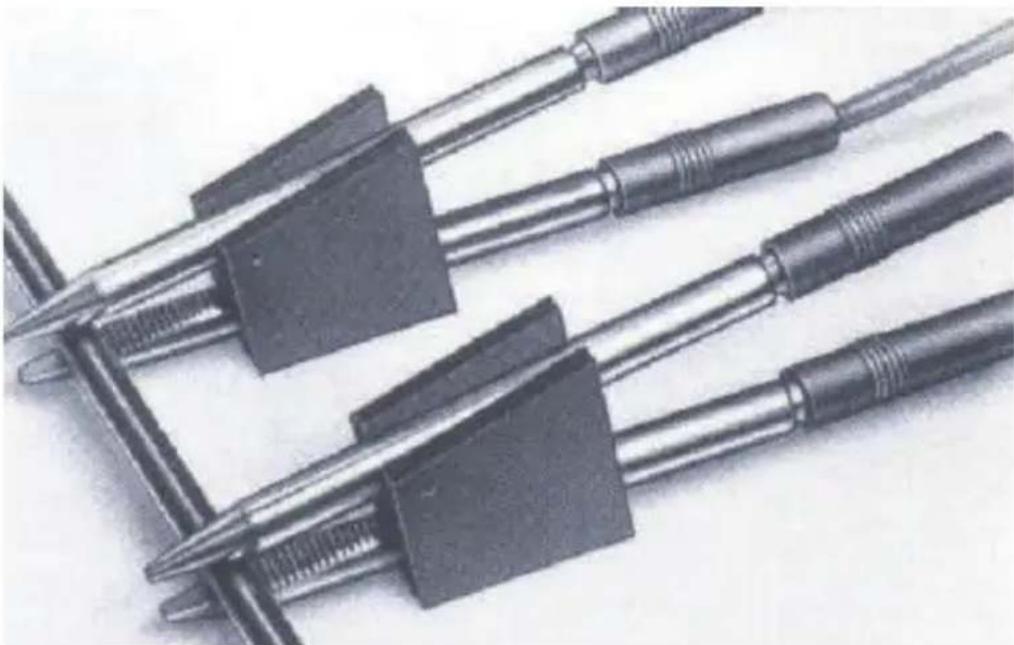
natural_image
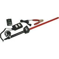
Close-up of metallic mechanical clamps with threaded connectors (no visible text or symbols)Fig. 9.1 Combined current and potential probes (Kelvin clips)
c) It is not always possible to use the combined current and potential clips, in which case test leads with spade tags or special test fi xtures may have to be made for the user to suit particular applications.
d) Fig. 9-2 illustrates connections to various types of test resistors.
e) When measuring 4-terminal resistance standards, do not use the combined current and potential probes. Make four separate connections to the current and potential terminals.

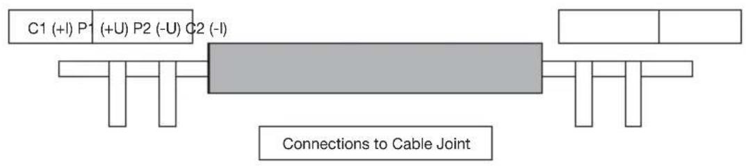
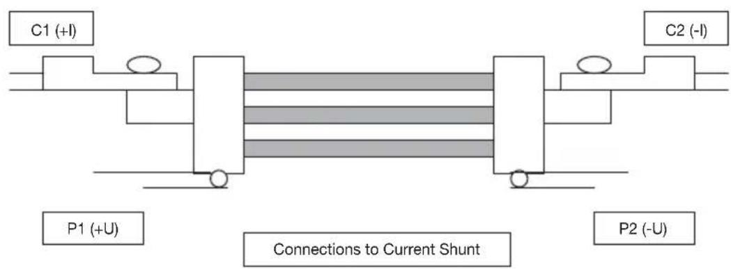
Fig. 9.2 Various types of resistors
10. POWER UP
When the DO7e is first switched on, an internal self-test is automatically performed. The display indicates -8888 followed by PASS and then switches to standby mode ready for measurement. Should the internal checks indicate an error, then the display will read "HELP". Contact our Service Department or your local agent for assistance.
The DO7e will perform an automatic zero sequence and finally sets to the following default start-up mode ready for use. The selected measuring range will be 600Ω, and the DO7e will then be in stand-by mode. The display will blank after approx. 25 seconds.
11. MEASUREMENT
Connect the resistance to be measured (Rx) to the measuring terminals in accordance with the diagram on the instrument panel. Select the range required or Auto range, and the current measurement mode, ie. +, -or average. The LED lamps will light to indicate which buttons are active. To initialise the measurement, press the MEAS button, a single measurement will be initialised and the value held on the display for approximately 25 seconds. After 25 seconds have elapsed the display will blank with only the range LED alight, the last measured value may be recalled to the display by pressing the MEAS key. To make another measurement the MEAS key should be pressed again Should you wish to initialise a continuous reading, then press and hold the MEAS key until a long bleep is heard this will lock the measurement in continuous mode. Note continuous measurement is not possible on the lowest 6mΩ range. The measurement will continue until the MEAS key is pressed again. The DO7e will automatically power off after 5 minutes with no key activity to preserve battery life. Note: the MEAS key LED will be lit whilst a measurement is in progress.
Current Mode
The current mode can be set to measure with +I, -I or AVE. The AVE mode should be selected for all measurements that are not inductive, as this eliminates errors due to thermal emf in the measurement circuit or test leads. In the AVE mode the DO7e measures with the current in both directions and displays the average of the two readings. For measurement of inductive circuits the measuring current should either be set in + or - mode.
Over-Range
The display will indicate - - - .
Select a higher range.
Open Circuit Lead
O/C LEAD LED will light and the display will indicate - - - if the instrument detects that the lead resistance is too high. ( The C terminals are checked for compliance voltage). Measurement cannot be made if this warning message is displayed. This warning will also be displayed if the internal protection fuse is open-circuit.
When in STANDBY mode this LED will always be lit.
Low Battery
The LOBAT LED will light when the battery has approx. 10% charge left, when this LED lights the DO7e should be connected to a mains supply and the batteries automatically recharged. Full measurement accuracy is maintained even when the LOBAT LED is lit.
12. Connections
When making good quality measurements, it is important to ensure that all measuring leads are in good condition, and less than 0.2 ohms resistance.
It should also be noted that some spade tags and crocodile clips can produce high thermal emfs when warmed, particularly nickel-plated brass types. This can cause problems when, for example, connecting too hot motor windings. The solution is to use plain copper or brass connections keeping them clean and oxide-free.
Measuring Terminals
The heavy duty measuring terminals are designed to accept 4mm banana plugs in the top socket, Bare wires and spade tags may also be clamped in the side entry socket.
13. REMOTE
If a footswitch, test leads with start button or other similar external switch is plugged into the REMOTE socket, it will behave as the MEAS key.
14. PROTECTION
Every effort has been made to protect the instrument against voltages being applied to the terminals. A large 6 Amp fuse is fitted internally to the C measuring line and a gas discharge tube, GDT, is across the C terminals. If voltages above approximately 90V are applied to the measuring terminals, the GDT will strike, effectively shorting the C terminals through the 6 Amp protective fuse, which will interrupt the circuit.
The fuse fitted will interrupt up to 40,000 Amps. The P terminals are not fused and will withstand up to 460 Volts without damage to the instrument.
WARNING!
To replace the protection fuse, the top instrument panel should be removed, but only after the mains supply and all input connections are removed. The protection fuse is located on the main printed circuit board. Only replace with the correct fuse rating.
15. CALIBRATION PROCESS
This procedure describes the standard calibration method for the D07e Ohmmeter using Cropico Calibration Standard Type MTS2. If discrete resistance standards are to be used instead, refer to section 21 before proceeding.
CAUTION
The DO7e will be factory-calibrated to its full accuracy when delivered and any recalibration by the user will invalidate this initial calibration. The user should therefore be certain that only authorised and competent personnel are permitted access to the calibration facility, which is code protected.
16. EQUIPMENT REQUIRED
Cropico Calibration Standard Type MTS2 Set of 2 low thermal emf leads Set of 2 general purpose leads (10A rating)
17. PREPARATION
17.1 Ensure all retaining screws are fitted.
Place unit in temperature controlled environment for a minimum of 4 hours. Ensure batteries are fully charged.
17.2 Connect each of the four DO7e terminals to the equivalent terminals on the calibration Standard. It is essential that low thermal emf leads are used for the P1 and P2 leads (see Fig.17.1 for the preferred setup).
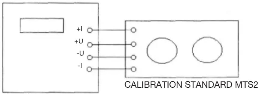
P1, P2 LEADS - PURE COPPER, MULTI STRANDED C1, C2 LEADS - 10A RATING (55/0.15MM)
17.3 An internal battery powers the DO7e and this should be fully charged before carrying out the calibration. The mains charger can be left connected, if desired.
17.4 Set the calibration standard to 400 Ohm, Zero.
17.5 Turn the DO7e power ON whilst holding down the CAL key.
17.6 Leave for a few minutes to stabilise.
18. CALIBRATION
ENTERING A PASSCODE & CALIBRATION
- Hold down CAL key, whilst powering up - the DO7E displays 'CODE'.
-
Enter the 4-digit passcode (default is 9252) and press OK.
-
If the code was incorrect, a long beep is emitted, and the user should start again from #2.
-
If correct, the DO7e displays zero (eg '0.0'), and is now in Calibration mode.
-
At this point, a specific range can be chosen for calibration by pressing the relevant range key. Otherwise, each range will be selected in turn automatically, starting with 600W.
-
With the display showing zero, select the correct resistor value and the ZERO setting on the calibration box, and press OK. If there is an error, a long beep will be emitted, and the user should check the settings, and repeat #6.
-
If the zero measurement is successful, a short beep is emitted, and the full-scale value is displayed (eg 600.0).
-
Select FULL SCALE on the calibration box.
- Then enter the exact value of the standard resistor, using all four digits (eg 300.0) - the decimal point will be added automatically - and press OK.
- If the entered value is outside the allowed limits, a long beep will be emitted immediately, and the user should go back to #9.
- If the entered value is OK but there is an error in the measurement, a long beep will be emitted at the end of the measurement. The user should check the settings, and go back to #8.
- If the full-scale measurement is successful, a short beep will be emitted, and the user is returned to #4 with the next range down already selected.
Note:
Calibration mode can be exited by pressing the CAL key at any time, except when a number is being entered.
Partially-entered codes or values can be cleared at any time by pressing CLE, and then reentered.
Ideally, the DO7e 600W range should be calibrated against a 600Ω standard, but the software will allow any value between 90Ω and 606Ω. Similar ratios apply to the other ranges.
CHANGING A PASSCODE
- Carry out #1 to #4 as above, using the existing passcode.
- Press and hold the CLE key for 2 seconds - the DO7e displays 'CODE'.
- Enter the new 4-digit passcode and press OK - the DO7e displays 'CODE' again.
- Re-enter the new 4-digit passcode and press OK.
- If the new passcode was not entered correctly both times, a long beep will be emitted, and the process must be repeated from #3.
- If correct, the DO7e displays zero (eg '0.0'), and is now in Calibration mode. If this is not required, it can be exited by pressing CAL.
** END OF NORMAL CALIBRATION PROCEDURE **
19. USING DISCRETE RESISTANCE STANDARDS
20.1 Discrete, 4-terminal resistance standards may be used in place of the Cropico Calibration Standard. The standards must have an uncertainty better than 0.01% if the full calibration accuracy is to be achieved. Full consideration of the DO7e measuring current must also be taken into account when selecting the standards. The DO7e can be calibrated to standards between 1000 and 6000 digits for each range using the KYB entry. However, full accuracy will only be achieved if standards of 4000 to 6000 digits are used. The following nominal standards are recommended:
400, 40, 4, 400m, 40m and 4m Ohm
20.2 In all measurements the P1 and P2 terminals are conventionally connected. Bear in mind that thermal emfs may be present. The DO7e is particularly sensitive to these on the 6m Ohm range.
20.3 For FS measurements, connect the C1 and C2 leads in the conventional manner (see Fig 20.1).
20.4 For ZERO measurements, connect the C1 and C2 leads to the C2 terminal of the standard (see Fig 20.2).
FULL SCALE CALIBRATION
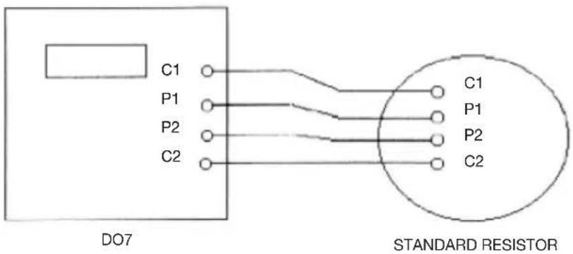
P1, P2 LEADS - PURE COPPER, MULTI STRANDED C1, C2 LEADS - 10A RATING (55/0.15MM)
Fig. 20.1
ZERO CALIBRATION
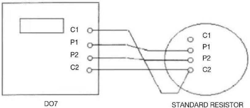
P1, P2 LEADS - PURE COPPER, MULTI STRANDED C1, C2 LEADS - 10A RATING (55/0.15MM)
Fig. 20.2
** END OF TEST PROCEDURE **
Remote Start Socket
Connect remote switch to pins 1 and 2 when switch closed it acts as MEAS key

flowchart
graph TD
    A["3"] --> B["2"]
    C["1"] --> D["2"]
    style A fill:#fff,stroke:#000
    style B fill:#fff,stroke:#000
    style C fill:#fff,stroke:#000
    style D fill:#fff,stroke:#000
Viewed from panel
20. AVAILABLE ACCESSORIES
MEASURING LEADS
The DO7e may be used with a variety of lead sets. The following are the available selection. Remember, if you do not see suitable leads for your application, please consult our customer help desk.
| Ordering Code | Description |
| HS01-P | Duplex Handspikes with 2.5 metre lead length, current and potential spikes suitable for plate or Bussbar measurements. |
| HS02-P | Duplex Handspikes as a HS01-P but with 2.5 and 15 metre lead lengths |
| HS03-P | Large Kelvin clips with 3 metre lead length suitable for attaching to rods bars or cables up to 38mm diameter |
| HS04-P | As LS03-P but with lead lengths 3 and 15 metres |
| LS05 | Executive lead set consisting of 4 x 1 metre leads with banana plugs, 4 x crocodile clips 4 x test prods and 4 x Kelvin clips (KC1) jaw opening 4mm |
| LS06-P | Kelvin lead set comprising of miniature Kelvin clips (KC2) with 1 meter leads attached terminated with banana plugs Jaw opening 6mm. Suitable for fi ne wires. |
WIRE CLAMPS
For the precise measurement of 1 meter cable samples we offer 3 wire clamp options.
| Ordering Code | Description |
| C02 | 1 metre wire clamp with hardwood base suitable for cable diameters up to 100mm |
| C02-A | 1 metre wire clamp with metal base and provision for temperature sensor suitable for wire cross section 1 to 1000mm |
| CO3 | 1 metre wire clamp with water bath for the precise measurement of 1 meter cable samples 1 to 1000mm |
TEMPERATURE PROBE
| Ordering Code | Description |
| 5000-Pt100 | Pt100 Temperature Sensor Probe length 200mm, diameter 6mm.Fitted with 1 Metre Lead and DIN Plug |
| Ordering Code | Description |
| MTS2 | Calibration Standard |
CE Declaration of Conformity
Manufactured by:
Seaward Electronic Ltd, Bracken Hill, South West Industrial Estate Peterlee, County Durham, SR8 2SW, England
Statement of Conformity
As the manufacturer of the apparatus listed, declare under our sole responsibility that the product:
Cropico DO7e Ohmmeter
To which the declaration relates are in conformity with the relevant clauses of the following standard(s):
BS EN61010-1:2010
Safety requirements for electrical equipment for measurement, control, and laboratory use - Part 1: General requirements.
BS EN61010-2-030:2010
Safety requirements for electrical equipment for measurement, control, and laboratory use - Part 2-030: Particular requirements for testing and measuring circuits.
BS EN61326-1:2006
Electrical equipment for measurement, control and laboratory use - EMC requirements - Part 1: General requirements.
Performance: The instrument operates within specification when used under the conditions in the above EMC and Safety Standards.
The product identified above conforms to the requirements of Council Directive 2004/108/EC and 2006/95/EC.
This Conformity is indicated by the symbol CE , i.e. "Conformité Européenne"
Seaward Electronic Ltd. is registered under BS EN ISO9001:2000 Certifi cate No.: Q05356.
For Technical Support Contact:
Tel: +44 (0) 191 587 8718
For Service and Calibration Contact:
Service Department
Seaward Group
Unit 11
Bracken Hill
South West Industrial Estate
Peterlee
Co Durham
SR8 2LS
England
Tel: +44 (0) 191 587 8739
Fax: +44 (0) 191 587 8737
E-mail: service@seaward.co.uk
CROPICO is a division of

SEAWARD
GROUP
Additional Products From Cropico
DIGITAL OHMMETERS
RESISTANCE BRIDGES
RESISTANCE DECADE BOXES
RESISTANCE STANDARDS
DIGITAL THERMOMETERS
THERMOCOUPLE SIMULATORS
PT100 SIMULATORS
INSULATION TEST SETS
UNIVERSAL CALIBRATORS
HIPOT TESTERS
ELECTRICAL SAFETY TESTERS

CROPICO
Phone, fax or e-mail for further information on the above or for a copy of our general catalogue: - Phone: - +44 (0) 191 5863511
Fax: - +44 (0) 191 5860227
E-mail:- sales@cropico.com
Website: - www.cropico.com


- Digital Microhmmeter Type D07e
- CROPICO
- Limited Warranty & Limitation of Liability
- Copyright 2013
- Disposal of Old Product
- Supplied Accessories: 3
- IMPORTANT NOTE
- Supplied Accessories:
- SAFETY
- WARNING!
- INTRODUCTION
- Display range 6000
- MEASURING PRINCIPLE
- CASE DESIGN
- MAINTENANCE
- BATTERY CHARGING
- BATTERY
- BATTERY REPLACEMENT
- TECHNICAL DATA
- Measurement
- DESCRIPTION OF CONTROLS
- Measurement Polarity
- Range Selection:
- Error & Status Lamps
- METHODS OF MEASUREMENT
- Ohmmeter Connections
- POWER UP
- MEASUREMENT
- Current Mode
- Over-Range
- Open Circuit Lead
- Low Battery
- Connections
- REMOTE
- PROTECTION
- CALIBRATION PROCESS
- CAUTION
- EQUIPMENT REQUIRED
- PREPARATION
- CALIBRATION
- ENTERING A PASSCODE & CALIBRATION
- Note:
- CHANGING A PASSCODE
- USING DISCRETE RESISTANCE STANDARDS
- Remote Start Socket
- AVAILABLE ACCESSORIES
- MEASURING LEADS
- WIRE CLAMPS
- CE Declaration of Conformity
- Cropico DO7e Ohmmeter
- For Technical Support Contact:
- For Service and Calibration Contact:
- Additional Products From Cropico
Brand : Seaward
Model : DO7e
Category : Measurement