
Spectra SS-UV10 - Lighting Altman - Free user manual and instructions
Find the device manual for free Spectra SS-UV10 Altman in PDF.


| Product Type | LED UV Lighting Fixture |
| Brand | Altman Lighting |
| Model | Spectra SS-UV10 |
| Light Source | UV LEDs (wavelength unspecified, typical 365-395 nm) |
| DMX Protocol | DMX512 and RDM compliant |
| DMX Resolution | 8-bit and 16-bit selectable |
| Personalities | 12 programmable personalities (including single-color modes 609-612) |
| Smoothing | Selectable ON/OFF for smooth dimming |
| Master Control Mode | Enable to control multiple fixtures as master |
| Stand-Alone Effects | Color fades and strobes (speed adjustable) |
| Local Channel Control | Manual color selection via onboard buttons |
| Keypad Lock | Prevents accidental reprogramming |
| DMX Addressing | Push-button setting, range 1-512 |
| DMX Data Through | Maximum total run 1000 ft (305 m) |
| Power Supply | Onboard, AC input (typical 100-240V, 50/60 Hz) |
| Power Consumption | Approx. 50W (estimated for UV model) |
| Dimensions (approx.) | 10.5 x 7.5 x 5.5 inches (267 x 191 x 140 mm) |
| Weight (approx.) | 4.5 lbs (2 kg) |
| Environment | Indoor use only (IP20 typical) |
| Warranty | 3 years for LED light source |
| Safety Standards | Install per National Electrical Code, qualified electrician required |
Frequently Asked Questions - Spectra SS-UV10 Altman
User questions about Spectra SS-UV10 Altman
0 question about this device. Answer the ones you know or ask your own.
Ask a new question about this device
Download the instructions for your Lighting in PDF format for free! Find your manual Spectra SS-UV10 - Altman and take your electronic device back in hand. On this page are published all the documents necessary for the use of your device. Spectra SS-UV10 by Altman.
USER MANUAL Spectra SS-UV10 Altman
natural_image
Abstract 3D geometric shape with gray and white segments on orange background (no text or symbols)
LIGHTING

natural_image
Product display of various lighting and equipment items including cylindrical and rectangular units, a monitor, and a multi-light range device (no visible text or symbols)SPECTRA SERIES
Programming Manual
Have a question regarding this manual?
The material in this manual is for information purposes only and is subject to change without notice. Altman Lighting assumes no responsibility for any errors or omissions which may appear in this manual.
Should you find an error, have a suggestion or question regarding your Altman Lighting product, we would love to hear from you.
You can reach us at:
Altman Lighting
1400 East 66th Avenue
Denver, CO 80229
1-303-500-7072 (Main)
www.altmanlighting.com
customerservice@altmanlighting.com
Note: Information contained in this document may not be duplicated in full or in part by any person without prior written approval of Altman Lighting. Its sole purpose is to provide the user with conceptual information on the equipment mentioned. The use of this document for all other purposes is specifically prohibited.
The material in this manual is for information purposes only and is subject to change without notice. Altman Lighting assumes no responsibility for any errors or omissions which may appear in this manual. For comments and suggestions regarding corrections and/or updates to this manual, please visit the Altman Lighting web site at www.altmanlighting.com or contact your nearest Altman Lighting Regional Manager.
Altman Lighting continually engages in research related to product improvement. New materials, production methods and design refinements are introduced into existing products without notice as a routine expression of the philosophy. For this reason any current Altman Lighting product may differ in some respect from its published description, but will always equal or exceed the original design specifications unless otherwise noted.
Manual Part Number: 49-0270
Version as of: 4 February 2021
Spectra Series Products Programming Manual
©2021 Altman Lighting. All rights reserved.
Product Safety Notices
When using electrical equipment, basic safety precautions should always be followed including the following:

a. READ AND FOLLOW ALL SAFETY INSTRUCTIONS.
b. Do not use outdoors unless the product is specified to operate in outdoor environments.
c. Do not mount near gas or electric heaters.
d. Equipment should be mounted in locations and at heights where it will not readily be subjected to tampering by unauthorized personnel.
e. The use of accessory equipment not recommended by the manufacturer may cause an unsafe condition.
f. Do not use this equipment for other than intended use.
g. Refer service to qualified personnel.
SAVE THIS MANUAL FOR FUTURE REFERENCE.
Warnings

WARNING: You must have access to a main circuit breaker or other power disconnect device before installing any wiring. Be sure that power is disconnected by removing fuses or turning the main circuit breaker off before installation. Installing the device with power on may expose you to dangerous voltages and damage the device. A qualified electrician must perform this installation.
WARNING: Refer to National Electrical Code® and local codes for cable specifications. Failure to use proper cable can result in damage to equipment or danger to personnel.
WARNING: This equipment is intended for installation in accordance with the National Electric Code® and local regulations. It is also intended for installation in indoor applications only. Before any electrical work is performed, disconnect power at the circuit breaker or remove the fuse to avoid shock or damage to the control. It is recommended that a qualified electrician perform this installation.
WARNING: This Lighting Fixture IS NOT for residential installation or use.
THIS PRODUCT MUST BE INSTALLED IN ACCORDANCE WITH THE APPLICABLE INSTALLATION CODE BY:
A PERSON FAMILIAR WITH THE CONSTRUCTION AND OPERATION OF THE PRODUCT AND THE HAZARDS INVOLVED.
CE PRODUIT DOIT ÊTRE INSTALLÉ SELON LE CODE D'INSTALLATION PERTINENT, PAR UNE PERSONNE
Altman Lighting Product Warranty
Warranty Term
Altman Lighting, Inc., a subsidiary of Altman Stage Lighting Company, Inc., herein referred to as Altman, warrants each new product (except for spare parts or products Altman does not manufacture) for a period of TWO (2) years from date of shipment to correct by repair or replacement any part defect due to faulty material or workmanship. Under these same terms products with an LED light source shall be warranted for a period of THREE (3) years.
Altman warrants for NINETY (90) days any spare part it manufactures. On spare parts or products Altman does not manufacture, including, but not limited to, lamps, sockets, lenses, roundels, electronics, ignitors, ballasts, etc.; Altman will grant the same warranty given Altman by its vendors.
Altman assumes no responsibility for damage or faulty performance caused by misuse, improper installation, careless handling or where repairs have been attempted by others.
This warranty is in lieu of all warranties or guarantees expressed or implied and no representative or person is authorized to assume Altman any other liability with the sale of Altman's products.
For complete warranty terms and conditions, please refer to our web site at www.altmanlighting.com.
Warranty Service
In order to request warranty service, you must receive a Return Material Authorization (RMA) number prior to return.
Return shipments must be visibly marked with the RMA number; the product must be returned (shipping prepaid) to the factory at:
Altman Lighting Inc.
Attention: RMA # ____
1400 East 66th Avenue
Denver, CO 80229
The return must be within THIRTY (30) days of receiving the RMA from Altman.
TABLE OF CONTENTS
Have a question regarding this manual?...... Inside Front Cover
Our Commitment .... Inside Front Cover
Important Information
Product Safety Notices....1
Warnings 1
Altman Lighting Product Warranty.... 2
Warranty Term.... 2
Warranty Service 2
Table of Contents
Preface
About this Manual 4
Products Covered 4
Common Features 4
Programming Buttons Overview 4
Programming and Settings
DMX Mode 5
Personalities....5
Personality Settings....7
Personality Meanings 7
Smoothing 8
Stand-Alone Effects Mode 9
Setting DMX Address.... 10
Local Channel Control.... 10
Selecting Colors in Local Channel Control 10
Master Control Mode.... 11
Enabling Master Control Mode 11
Disabling Master Control Mode 12
Locking the Fixture's Buttons (Locked Mode).... 12
About this Manual
This document only provides programming information for Spectra Series Products. For installation and operation information, please refer to the specific product's quick start guide or user's manual.
Retain this manual for future reference.
Products Covered
This manual covers the all Spectra Series Products models except as noted in this document. If you ever need assistance or have a question regarding your Altman Lighting product, please contact technical support at 1-303-500-7072 or email us at customerservice@altmanlighting.com.
Common Features
Spectra Series Products offer the following common features. For complete product details, refer to the product's specification sheet located on the Altman Lighting web site at www.altmanlighting.com.
- Compatible with DMX512 and RDM protocols.
- 8 and 16-bit DMX512 control for smoother dimming.
- On board power supply, microprocessor controller, and current drivers.
- Feed through DMX/RDM data with a maximum total run of 1000 feet.
- Push button addressing.
- Twelve (12) personalities Local Channel Control Stand Alone Effects.
- Keypad Lock functions to prevent accidental re-programming.
Programming Buttons Overview
Spectra Series Products offer three (3) buttons to program the fixture. With these three buttons, you can program or set. To activate the three digit display, press any of the three button. After 4 seconds of inactivity, the display will go blank.

Figure 1: Spectra Series Three Digit Display and Programming Buttons
- DMX Address
• Personalities (twelve choices) - Stand-Alone Effects
- Local Channel Control
- Lock the Fixture (from unwanted changes after programming)
- Master Control Mode
DMX Mode
DMX Mode is used for Personalities ("Personalities" on page 5), Stand-Alone Effects ("Stand-Alone Effects Mode" on page 9), and Setting DMX Address ("Setting DMX Address" on page 10).
To Switch to DMX Mode to or from Local Channel Control (refer to "Local Channel Control" on page 10):
Step 1. Wait until the display goes blank.

Figure 2: Setting Unit to DMX Mode
Step 2. As shown in Figure 2, PRESS and HOLD [ONES] button.
Step 3. PRESS and HOLD [TENS] button.
Step 4. RELEASE [ONES] button.
Step 5. RELEASE [TENS] button.
Personalities
There are 12 programmable operational Personalities the luminaire can be set to. Each Personality is comprised of three settings:
• DMX Resolution (either 8-bit or 16-bit)
• Master Control Mode (On or Off)
- Smoothing (On or Off)
All are described within this section.
The current set Personality alpha-numeric number is displayed for about one second during luminaire power up. The format is shown in Figure 3. "P" designates Personality setting and "XX" is 01 through 12 is the specific setting of the Personality.

Note: Value shown on display is an example only.
Figure 3: Personality Setting
To set the luminaire's Personality:
Note: The unit must be set to DMX Mode (not Fixed Color mode) prior to setting the Personality. Refer to "DMX Mode" on page 5 for more information.
Step 1. Press programming buttons until desired Personality address appears (refer to Table 1 on page 7).
Step 2. Wait a few seconds and a conformation display will appear with a question mark (?) in the hundreds digit and the Personality in the next two digits as illustrated in Figure 4. This is to confirm (or reject) the Personality shown.
- To accept new Personality, press [ONES] button.
- To reject new Personality, press [HUNDREDS] button.

Note: Value shown on display is an example only.

1's Button - Press to ACCEPT setting.
100's Button - Press to REJECT setting.
Figure 4: Personality Setting - Confirm Setting
Note: Once Personality is set, it remains in the luminaire's memory and retained even if power is disconnected. The factory default Personality for RGBA or RGBW fixtures is P02. Single color fixtures, such as UV or White, are shipped set to Personality P10.
Note: For single color fixtures (such as UV or White) only Personalities 609 (P09), 610 (PI0), 611 (PII), or 612 (PI2) should be used. In the case of the SSUV30 and SSUV40 units, they can be set to four color control. This setting will allow for interdependent control over each UV Pod.
Step 3. After setting or rejecting Personality, luminaire display will show current DMX address.
Personality Settings
Table 1: Personality Settings / Descriptions
| Value Description DMX Mode / Channel Order | Master Channel | Smoothing | ||
| FOUR COLOR CHANNELS | ||||
| 601 Personality 1 - Uses four DMX channels 8-bit / RGBA OFF OFF | ||||
| 602 | Personality 2 - Uses four DMX Channels | 8-bit / RGBA | OFF | ON |
| 603 | Personality 3 - Uses five DMX Channels | 8-bit / RGBAM | ON | OFF |
| 604 | Personality 4 - Uses five DMX Channels | 8-bit / RGBAM | ON | ON |
| 605 | Personality 5 - Uses eight DMX Channels | 16-bit / RrGgBbAa | OFF | OFF |
| 606 | Personality 6 - Uses eight DMX Channels | 16-bit / RrGgBbAa | OFF | ON |
| 607 | Personality 7 - Uses ten DMX Channels | 16-bit / RrGgBbAaMm | ON | OFF |
| 608 | Personality 8 - Uses ten DMX Channels | 16-bit / RrGgBbAaMm | ON | ON |
| ONE COLOR CHANNELS | ||||
| 609 | Personality 9 - Uses one DMX channel | 8-bit | N/A | OFF |
| 610 | Personality 10 - Uses one DMX channel | 8-bit | N/A | ON |
| 611 | Personality 11 - Uses two DMX channels | 16-bit | N/A | OFF |
| 612 | Personality 12 - Uses two DMX channels | 16-bit | N/A | ON |
Spectra Series fixtures have a number of different configurations RGBA (Red, Green, Blue, Amber) is shown in Table 1 and in the following section as an example of channel order layout.
- For Red, Green, Blue, White, use RGBW
- For Tunable White 3K/6K, use 3K, 3K, 6K, 6K as the channel order
- For fixed color or white only LED units, use modes 609 to 612
Personality Meanings
DMX Resolution 8-bit (Four Channels) 601, 602
8-bit mode (one DMX channel per color) this is normal resolution. If unit is in 8-bit mode, and the unit is set to DMX Channel 001, then the DMX channels would be:
• C H 1 R e d
• C H 2 Green
• C H 3 B l u e
- CH4 Amber (or White)
DMX Resolution 8-bit (Five Channels) 603, 604
If you are in 8-bit mode and the unit is set to DMX Channel 001, then the DMX channels would be:
• C H 1 R e d
• C H 2 Green
· C H 3 B l u e
• CH4 Amber (or White)
• CH5 Master Channel*
Note: *Master Channel is selectable as ON or OFF and provides a master fade channel that dims all 4 colors proportionally at the same time in order to maintain the color throughout the fade.

IMPORTANT! SS-UV 30 and SS-UV40 fixtures. For these fixtures, each channel will control each pod individually. For example, on the SS-UV40 - when set to mode 602 - each pod will be controlled (individually) via each control channel.
DMX Resolution 16-bit (Eight Channels) 605, 606
16-bit mode (two DMX channels per color - Coarse + Fine) is similar to moving lights. If unit is in 16-bit mode, and the unit was set to DMX Channel 001, then the DMX channels would be:
- CH1 R ed Coarse
- CH2 Red Fine
- CH3 Green Coars e
- CH4 Green Fine
- CH5 Blue Coarse
- CH6 Blue Fine
• CH7 Amber (or White) Coarse
• CH8 Amber (or White) Fine
DMX Resolution 16-bit (Ten Channels) 607, 608
If you are in 16-bit mode and the unit is set to DMX Channel 001, then the DMX channels would be:
- CH1 Red Coarse
- CH2 Red Fine
- CH3 Green Coars e
- CH4 Green Fine
- CH5 Blue Coarse
- CH6 Blue Fine
• CH7 Amber (or White) Coarse
• CH8 Amber (or White) Fine - CH9 Master Coarse
- CH10 Master Fine
Smoothing
Smoothing is selectable as ON or OFF. When set to ON, Smoothing provides a smooth transition ramp from one level to another - similar to how an incandescent lamp behaves. This feature helps to eliminate any “steppiness” associated with LED fixtures that is caused by the instantaneous response of fixture’s LEDs.
DMX Resolution 8-bit (One Channel) Personality 609 - Smoothing Off
If you are in 8-bit mode and the unit is set to DMX Channel 001, then the DMX channels would be:
• CH1 All Outputs - Smoothing Off
DMX Resolution 8-bit (One Channel) Personality 610 - Smoothing On
If you are in 8-bit mode and the unit is set to DMX Channel 001, then the DMX channels would be:
- CH1 All Outputs - Smoothing on
DMX Resolution 16-bit (Two Channels) Personality 611 - Smoothing Off
If you are in 16-bit mode and the unit is set to DMX Channel 001, then the DMX channels would be:
• CH1 All Outputs Coarse
- CH 2 All Outputs Fine
Note: The coarse and fine channels work in unison with each other. If only using the coarse channel in this mode the fade of the light will "step". When the fine channel is used in combination with the coarse channel, the fade of the luminaire will be smooth. It is always recommended that a control system that utilizes both coarse and fine channels be used when in this mode.
DMX Resolution 16-bit (Two Channel) Personality 612 - Smoothing On
If you are in 16-bit mode and the unit is set to DMX Channel 001, then the DMX channels would be:
• CH1 All Outputs Coarse
• CH 2 All Outputs Fine
Note: The coarse and fine channels work in unison with each other. If only using the coarse channel in this mode the fade of the light will "step". When the fine channel is used in combination with the coarse channel, the fade of the luminaire will be smooth. It is always recommended that a control system that utilizes both coarse and fine channels be used when in this mode.
Stand-Alone Effects Mode
Stand-Alone Effects Mode is used when a DMX controller or control console is not available or desired.
Note: The unit must be in DMX Mode (refer to "DMX Mode" on page 5). If Master Control Mode is ON, stand-alone effects from a single unit will control all other units connected via DMX cable. To all synchronize the units, set their DMX address to 001.

IMPORTANT! Do not use the Stand-Alone Effects Mode while connected to a control console or a conflict in operation (between the DMX controller or console and the unit sending commands) will result.
Table 2: Stand-Alone Effects Settings
| Value Range Description Comments | ||
| Color Fades (700 to 799) | ||
| 700 to 709 R >> A >> G >> B Fade 700 = Fast to 709 = Slow | ||
| 740 to 749 B >> G >> A >> R Fade 740 = Fast to 749 = Slow | ||
| 780 to 789 R >> A >> G >> B >> W Fade 780 = Fast to 789 = Slow | ||
| 790 to 799 W >> B >> G >> A >> R Fade 790 = Fast to 799 = Slow | ||
| Strobes (800 to 879) | ||
| 800 to 819 White Strobe 800 = Fast to 809 = Slow | ||
| 820 to 829 Red Strobe 820 = Fast to 829 = Slow | ||
| 830 to 839 | Green Strobe | 830 = Fast to 839 = Slow |
| 840 to 849 | Blue Strobe 840 = Fast to 849 = Slow | |
| 850 to 859 | Red / Amber / Green / Blue - Rainbow Strobe | 850 = Fast to 859 = Slow |
| 870 to 879 | Blue / Green / Amber / Red - Rainbow Strobe | 870 = Fast to 879 = Slow |
Setting DMX Address
To set the luminaire's DMX address, simply press the unit's three buttons (Figure 5) repeatedly (or press and hold and the numbers will sequence automatically) desired DMX address (1 through 512) appears on the display. After a few seconds after the last button press, the display will blink once quickly, and the address is set.

Figure 5: Setting DMX Address

The address is retained in memory, even if disconnected from its power source.
IMPORTANT! RDM addressing sent from a remote unit will overwrite local DMX settings.
Local Channel Control
Local Channel Control is a special mode that allows you to manually select colors for a single unit using the luminaire's three buttons. Special Note: for one color units display will still reflect R,G,B,A, which will drive the outputs of channels 1-4.
To Switch to Local Channel Control to or from DMX Mode (refer to "DMX Mode" on page 5):
Step 1. Wait until the display goes blank.

Figure 6: Setting Unit to Local Channel Control
Step 2. As shown in Figure 6, PRESS and HOLD [ONES] button.
Step 3. PRESS and HOLD [TENS] button.
Step 4. RELEASE [ONES] button.
Step 5. RELEASE [TENS] button.
Selecting Colors in Local Channel Control
- While in Local Channel Control, the hundreds button cycles through Red, Green, Blue, and Amber (or White) colors.
- The tens and ones buttons will display a value between 0 through 99. Note, value 99 is channel at full.
Master Control Mode
Note: Master Control Mode is different than Master Channel described in "Personality Settings" on page 7.
Master Control Mode only works while the unit is set to Stand-Alone Mode (refer to "Stand-Alone Effects Mode" on page 9). This mode allows the unit set to Master Control Mode to behave like a DMX control source or console and transmit 4-channel (RGBA) 8-bit DMX set on DMX address 001 - reflecting its present light output.
Master Control Mode Notes
- Only the first unit in the DMX chain is going to serve as the master fixture and it should be set to Stand-Alone Mode with Master Control Mode Channel set to ON.
- Stand-Alone Mode with Master Control Mode Channel ON should NOT be used while the units are connected to a DMX control device or console.
- All fixtures connected to and following the unit set to Master Control Mode should have their Master Control Mode Channel set to OFF.
Enabling Master Control Mode
To turn ON Master Control Mode:
Step 1. Set fixture to Stand-Alone Mode (see "Stand-Alone Effects Mode" on page 9)
Step 2. Allow display to go blank.

Figure 7: Setting Unit to Master Control Mode ON
Step 3. As shown in Figure 7, PRESS and HOLD [HUNDREDS] button.
Step 4. PRESS and HOLD [ONES] button.
Step 5. RELEASE [HUNDREDS] button.
Step 6. RELEASE [ONES] button.
Step 7. Display will briefly show ON to indicate unit is set to Master Control Mode and then blink.
Step 8. Address fixtures to DMX 001 that are connected to unit in Master Control Mode.
Disabling Master Control Mode
To turn OFF Master Control Mode:
Step 1. Allow display to go blank.

Figure 8: Setting Unit to Master Control Mode OFF
Step 2. As shown in Figure 8, PRESS and HOLD [HUNDREDS] button.
Step 3. PRESS and HOLD [ONES] button.
Step 4. RELEASE [HUNDREDS] button.
Step 5. RELEASE [ONES] button.
Step 6. Display will briefly show OFF to indicate unit is no longer set to Master Control Mode and then blink.
Locking the Fixture's Buttons (Locked Mode)
The luminaire can have its buttons disabled or locked so unwanted changes cannot be made.
To Lock (or Unlock) the fixture's buttons:
Step 1. Wait a few seconds until the display goes blank,

Figure 9: Setting Unit to Locked Mode ON or OFF
Step 2. As shown in Figure 9 on page 12. PRESS and HOLD [ONES] button.
Step 3. PRESS and HOLD [HUNDREDS] button.
Step 4. RELEASE [ONES] button.
Step 5. RELEASE the [HUNDREDS] button.
Step 6. Display will briefly show L0C to indicate unit is set to Locked Mode and then blink. In this mode, pressing the buttons will ave no effect until they are unlocked.

IMPORTANT! Locked Mode only affects the luminaire's buttons. The unit can still be addressed and changed via a RDM device.

LIGHTING
Altman Lighting
1400 East 66th Avenue
Denver, CO 80229
1-303-500-7072 (Main)
www.altmanlighting.com
© 2021 Altman Stage Lighting, Inc.

natural_image
Abstract 3D geometric shape with gray and white blocks against an orange background (no text or symbols)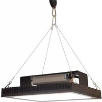
- Have a question regarding this manual?
- Product Safety Notices
- Warnings
- Altman Lighting Product Warranty
- Warranty Term
- Warranty Service
- TABLE OF CONTENTS
- Important Information
- Preface
- Programming and Settings
- About this Manual
- Products Covered
- Common Features
- Programming Buttons Overview
- DMX Mode
- Personalities
- Personality Settings
- Personality Meanings
- DMX Resolution 8-bit (Four Channels) 601, 602
- DMX Resolution 8-bit (Five Channels) 603, 604
- DMX Resolution 16-bit (Eight Channels) 605, 606
- DMX Resolution 16-bit (Ten Channels) 607, 608
- Smoothing
- DMX Resolution 8-bit (One Channel) Personality 609 - Smoothing Off
- DMX Resolution 8-bit (One Channel) Personality 610 - Smoothing On
- DMX Resolution 16-bit (Two Channels) Personality 611 - Smoothing Off
- DMX Resolution 16-bit (Two Channel) Personality 612 - Smoothing On
- Stand-Alone Effects Mode
- Setting DMX Address
- Local Channel Control
- Selecting Colors in Local Channel Control
- Master Control Mode
- Master Control Mode Notes
- Enabling Master Control Mode
- To turn ON Master Control Mode:
- Disabling Master Control Mode
- Locking the Fixture's Buttons (Locked Mode)
Brand : Altman
Model : Spectra SS-UV10
Category : Lighting