
BTR-80N - Intercom RTS - Free user manual and instructions
Find the device manual for free BTR-80N RTS in PDF.


| Product Type | Wireless Intercom Beltpack |
| Brand | RTS |
| Model | BTR-80N |
| Dimensions | 185 x 80 x 45 mm |
| Weight | 450 g without battery |
| Power Supply | Rechargeable Li-Ion battery, 12V DC input |
| Frequency Range | 2.402 – 2.483 GHz (ISM band) |
| Operating Range | Up to 300 m in open area |
| Number of Channels | 99 programmable |
| Audio Codec | Full-duplex, noise reduction |
| Main Functions | Full-duplex communication, group call, individual call, mute, volume control, channel scan |
| Display | OLED, 128 x 64 pixels |
| Connectors | 3.5mm headset jack, 2.5mm PTT, DC charging port |
| Battery Life | Up to 15 hours talk time |
| Charging Time | 3 hours |
| Environmental Protection | IP54 (dust and splash resistant) |
| Operating Temperature | -20°C to +60°C |
| Included Accessories | Belt clip, charging cradle, headset, AC adapter |
| Maintenance | Clean with soft dry cloth. Do not use solvents. |
| Safety | Use only approved charger. Do not expose to extreme heat. |
| Spare Parts Availability | Battery, headset, charging cradle available from RTS |
| Repair Service | Authorized service centers worldwide |
Frequently Asked Questions - BTR-80N RTS
User questions about BTR-80N RTS
0 question about this device. Answer the ones you know or ask your own.
Ask a new question about this device
Download the instructions for your Intercom in PDF format for free! Find your manual BTR-80N - RTS and take your electronic device back in hand. On this page are published all the documents necessary for the use of your device. BTR-80N by RTS.
USER MANUAL BTR-80N RTS
BTR-80N, TR-80N, TR-82N Professional Wireless Intercom System
Operating Instructions

natural_image
Exterior view of a black BTR-80N audio workstation with multiple RTS transceiver modules and control knobs (no readable text beyond branding)PROPRIETARY NOTICE
The product information and design disclosed herein were originated by and are the property of Bosch Security Systems, LLC. Bosch reserves all patent, proprietary design, manufacturing, reproduction, use and sales rights thereto, and to any article disclosed therein, except to the extent rights are expressly granted to others.
COPYRIGHT NOTICE
Copyright 2020 by Bosch Security Systems, LLC. All rights reserved. Reproduction, in whole or in part, without prior written permission from Bosch is prohibited.
*All other trademarks are property of their respective owners.
WARRANTY AND SERVICE INFORMATION
For warranty and service information, refer to the appropriate web site below:
RTS Intercoms ...... www.rtsintercoms.com/warranty
RTS Digital
RTSTW
AudioCom
RadioCom
Intercom Headsets
CUSTOMER SUPPORT
Technical questions should be directed to:
Customer Service Department
Bosch Security Systems, LLC
www.telex.com
DISCLAIMER
The manufacturer of the equipment described herein makes no expressed or implied warranty with respect to anything contained in this manual and shall not be held liable for any implied warranties of fitness for a particular application or for any indirect, special, or consequential damages. The information contained herein is subject to change without prior notice and shall not be construed as an expressed or implied commitment on the part of the manufacturer.

THE LIGHTNING FLASH AND ARROWHEAD WITHIN THE TRIANGLE IS A WARNING SIGN ALERTING YOU "DANGEROUS VOLTAGE" INSIDE THE PRODUCT.

CAUTION: TO REDUCE THE RISK OF ELECTRIC SHOCK, DO NOT REMOVE COVER. NO USER- SERVICABLE PARTS INSIDE. REFER SERVICING TO QUALIFIED SERVICE PERSONNEL.

THE EXCLAMATION POINT WITHIN THE TRIANGLE IS A WARNING SIGN ALERTING YOU OF IMPORTANT INSTRUCTIONS ACCOMPANY1 NG THE PRODUCT.
MARKING DEFINITION IF ON PRODUCT.
WARNING: APPARATUS SHALL NOT BE EXPOSED TO DRIPPING OR SPLASHING AND NO OBJECTS FILLED WITH LIQUIDS, SUCH AS VASES, SHALL BE PLACED ON THE APPARATUS.
WARNING: THE MAIN POWER PLUG MUST REMAIN READILY OPERABLE.
CAUTION: TO REDUCE THE RISK OF ELECTRIC SHOCK, GROUNDING OF THE CENTER PIN OF THIS PLUG MUST BE MAINTAINED.
WARNING: TO REDUCE THE RISK OF FIRE OR ELECTRIC SHOCK, DO NOT EXPOSE THIS APPRATUS TO RAIN OR MOISTURE.
WARNING: TO PREVENT INJURY, THIS APPARATUS MUST BE SECURELY ATTACHED TO THE FLOOR/WALL/RACK IN ACCORDANCE WITH THE INSTALLATION INSTRUCTIONS.

This product is AC or DC powered.

Important Safety Instructions
- Read these instructions.
- Keep these instructions.
- Heed all warnings.
- Follow all instructions.
- Do not use this apparatus near water.
-
Clean only with dry cloth.
-
Do not block any ventilation openings. Install in accordance with the manufacturer's instructions.
-
Do not install near any heat sources such as radiators, heat registers, stoves, or other apparatus (including amplifiers) that produce heat.
-
Do not defeat the safety purpose of the polarized or grounding-type plug. A polarized plug has two blades with one wider than the other. A grounding type plug has two blades and a third grounding prong. The wide blade or the third prong are provided for your safety. If the provided plug does not fit into your outlet, consult an electrician for replacement of the obsolete outlet.
-
Protect the power cord from being walked on or pinched particularly at plugs, convenience receptacles, and the point where they exit from the apparatus.
-
Only use attachments/accessories specified by the manufacturer.
-
Use only with the cart, stand, tripod, bracket, or table specified by the manufacturer, or sold with the apparatus. When a cart is used, use caution when moving the cart/apparatus combination to avoid injury from tip-over.
-
Unplug this apparatus during lightning storms or when unused for long periods of time.
-
Refer all servicing to qualified service personnel. Servicing is required if the apparatus is damaged in any way, such as: the power supply cord or plug is damaged, liquid is spilled or objects fall into the apparatus, the apparatus is exposed to rain or moisture, the apparatus is dropped, or the apparatus does not operate normally.
Table of Contents
Important Safety Instructions .... 3
INTRODUCTION......9
General Description 9
System Features 9
Controls and Connections 10
BTR-80N - Front Panel 10
BTR-80N - Rear Panel 11
Specifications 12
TR-80N - Top Panel 14
Specifications 16
TR-82N - Top Panel 18
Specifications 20
INSTALLATION ....19
Unpacking 19
Antenna Connection 20
Antenna Polarization 20
Distance between Antennas 21
Antenna Placement 21
Improving Reception and Increasing Range ..... 23
OPERATION 25
BTR-80N 25
Operation 25
Basic Operational Description 25
System Quick Start 25
Transmit and Receive Antennas 26
2-Wire Intercom Ports 26
4-Wire Intercom Ports 28
Auxiliary Input/Output 28
Base Station Link 29
Stage Announce (SA)/Relay 29
Base Station Link Jack 30
Program Jack 30
Powering the Base Station 31
Start Up Screen 31
Status Screen 31
RSSI Screen 32
Group/Channel Select Screen 32
Group/Channel Screen 32
Group/Frequency Screen 32
Frequency Edit (User-Defined Groups Only) ..... 33
Base Main Settings 33
TALK Button 33
Channel Select Button 33
Local Headset Volume and Gain 34
Base Transmitter Power 34
Squelch Settings 34
Stage Announce Level 35
Antenna Power 35
CAN Bus Number 36
Intercom Settings 36
2-Wire Intercom 37
4-Wire Intercom 37
Auxiliary Settings ....38
ClearScan 38
Lockout ....39
Copy 39
1st Use Defaults ....39
Factory Default 39
Connection of Multiple Base Stations
with the Link Cables ....40
Over-the-Air Data Links ....41
Master and Servant Base Stations ....43
CAN bus 43
Base Station Link Configurations ....45
Wireless Talk-Around Audio Only 46
Link Overview 46
Setup 47
WTA and a SINGLE CAN Bus Network .....47
Link Overview 47
Setup 48
WTA and Several CAN Bus Networks ....49
Link Overview 49
Setup 49
TR-80N/82N 52
Basic Operational Description ....52
System Quick Start 52
Battery Installation ....53
Headset Connection ....54
Sidetone ....54
Antenna Connection ....54
On/Off and Volume Control 55
TALK Button 55
Audio Channel Select Button 55
Stage Announce (SA) 56
Wireless Talk Around (WTA) 56
Groups and Channels ....57
Transmit Frequency 57
Receive Frequency 58
Microphone Gain 58
Battery Display 58
Low Battery Alert Tone ....59
Transmit Power 59
Changing the Transmit Power Setting ....59
Squelch Screen 60
Transmit Mode Screen 60
LEDs Off/On 60
Software Version/Band 61
ClearScan™ 61
Lock Out 61
First Use Default 61
Factory Reset 61
RF Monitor Screen 62
Setting Beltpack ID 62
On/Off and Volume Control 63
TALK Button 63
Stage Announce (SA) 63
Wireless Talk-Around (WTA) 64
Groups and Channels 65
Transmit Frequency 65
Receive Frequency 66
Microphone Gain 66
Battery Display 66
Low Battery Alert Tone 67
Transmit Power 67
Squelch Screen 68
Headphone Options: 68
Auxiliary Input: 68
Transmit Mode Screen 68
LEDs Off/On 69
Software Version/Band 69
ClearScanTM 69
Lock Out 69
First Use Default 69
Factory Reset 70
RF Monitor Screen 70
Setting Beltpack ID 70
BTR-80N Menu Structure 71
TR-80N Beltpack Screen Flowchart 73
TR-82N Beltpack Screen Flowchart 74
Frequency Bands 75
North America 75
Europe 75
Band Pairing for Systems 75
Frequency Plan 76
Troubleshooting 77
Battery Information 78
BatteryWarnings 78
Battery Life 78
Cold Temperatures and Batteries 78
2-Wire Systems Specification 79
Certificate Information 80
Accessories and Replacement Parts 83
Three (3) Band Base Stations 86
Identifying a Three (3) Band Unit 86
Regulatory Changes and the Three Band 86
Changing Channel Maps 86
General Description
RTS Wireless BTR-80N UHF Synthesized Wireless Intercom system offers reliable, high-performance, high-fidelity full-duplex communications delivered with minimum spectrum usage.
The BTN-80N system includes the BTR-80N frequency agile base station and up to four (4) TR-80N or TR-82N frequency agile beltpacks operating in full-duplex communications. An almost unlimited number of beltpacks may be used with a base station if the beltpacks are in Push-To TX mode (half-duplex).
The BTR-80N system incorporates two (2) audio channel operation, permitting the beltpack operator to choose between two (2) separate audio channels of communication, with the base station tracking the beltpack selection. This allows the user the flexibility to create a party line and a private line within the same beltpack.
The BTR-80N system is perfectly suited for standalone operation and can also interface with other RTS wired intercom systems. In addition to the external intercom systems interfaces, the system provides connections for auxiliary balanced audio input and output, as well as wireless talk-around (WTA) and stage announce (SA) features.
The BTR-80N system has been designed for reliable, efficient operation. Operating in the 482 to 722MHz range, the units perform reliably at line-of-sight distances of 1000 feet. With available antenna systems from RTS, the effective operating range can be extended. The high-efficiency beltpacks provide between 8 and 11 hours of uninterrupted operation using NiMH rechargeable battery packs.
System Features
- Frequency-agile base station and beltpacks. No external computer/device required to select frequencies.
- Backlit base-station LCD allows the user to easily monitor the beltpack's status and change base station frequencies.
- Squelch adjust on the BTR-80N, TR-80N, and TR-82N beltpacks.
- Beltpack's battery level displayed on the base station and in beltpack's menus.
- ClearScan function on base station and beltpack to automatically find the best channels on which to operate.
- Full-duplex (simultaneous talk and listen) or Push-to-Tx (half duplex) operation.
- Compatible with Audiocom (Telex), RTS TW and Clear-Com wired intercoms.
- Two (2) independent channels of intercom audio with the ability to operate party line and RTS matrix on the same intercom channel at the same time.
- WTA (Wireless Talk-Around) beltpack control. This feature allows beltpacks to talk to each other, but their audio is lifted from any wired system connected to the base station.
- SA (Stage Announce) beltpack control. Allows the user to direct their audio to a jack on the back of the base for P.A. systems or other external audio systems.
- Relay contact closure on the base when the SA button is pressed.
- TR-82N features two (2) audio channel binaural operation in either stereo or mono mode.
- TR-82N has a 1/8-inch (3.5mm) jack for auxiliary input from another audio source, such as an IFB, iPod, or other similar device.
- Beltpack units contained in a weather and shock resistant die cast magnesium case.
- Convenient IEC power connector on the base station so the unit can plug directly to outlets. No in-line or wall plug power supply.
- Dark mode configurable on TR-80N and TR-82N beltpacks. This shuts down all LEDs.
Controls and Connections
BTR-80N - Front Panel

FIGURE 1. BTR-80N - Front Panel
- Power Switch - Do not power up a base station within three (3) seconds of the unit being turned off. Voltages within the unit need to drop below a threshold before being repowered. If powered-up in less than three (3) seconds, the unit may boot as the wrong frequency band. Even with the unit powered down via the power switch, some circuits within the base remain energized. To completely remove power to the unit, disconnect the power cord.
- |MENU| and |SET| buttons - Use to select menus and set options on the LCD.
- Backlit Graphics LCD (Liquid Crystal Display)
- [UP] and [DOWN] buttons - Use to select base station options on the LCD.
- Portable Station Connect - Use buttons to enable or disable the respective receiver's audio. GREEN LED - Audio enabled, LED OFF - Audio disabled.
- 4-wire Selection/Peak Input Indicators - Displays when 4-wire intercoms are active with green indication. A red indication means the intercom input level is too high.
- 2-wire Selection/Peak Input Indicators - Displays which 2-wire intercoms are active with a green indication. A red indication means the intercom input level is too high.
- Auxiliary Selection/Peak Input Indicator - Displays if auxiliary input is on with a green indicator. A red indicator means the intercom input level is too high.
- Headset Intercom Select - Controls the intercom to which the local headset is connected. Each press of the button changes the connection to channel 1, channel 2, or both.
- Talk/Peak Light - LED is green when talk button #11 is active. A normal mic gain setting causes the LED to flash red on the loudest speech levels. If the gain is too high, the LED is red at normal speech volumes.
- Talk Button - Press to enable the audio path from the local handset. LED #10 turns green when enabled. A quick press and release latches button on. If the talk function is latched on, pressing the talk button again turns it off.
- Local Headset Connector - Male XLR connector or female XLR connector. A dynamic electret headset
microphone is automatically detected. Microphone gain and volume are configured in the software menus.

FIGURE 2. Local Headset Wiring
BTR-80N - Rear Panel

FIGURE 3. BTR-80N - Rear Panel
- Receive Antenna - Female "TNC" Connector. Color band on antenna must match color dot on base station.
- Relay Contact - A dry contact closure which activates when a beltpack user presses the stage announce (SA) button. Normally Open (NO). The rating is one amp at 24V maximum.
- Program Connector - Used to update software in unit.
- Base Station Link Jacks - When multiple base stations are connected through this jack, it allows wireless talk around (WTA) audio from the beltpacks to be routed from system to system. Also allows CAN bus data to be passed between base stations.
- Intercom 1 - Interface to wired intercom channel 1.
2-Wire - Male and female 3-pin XLR connectors wired in parallel. The connectors are switched to the appropriate intercom configuration via software.
4-Wire - An RJ-11 type jack compatible with Matrix type intercom systems.
- Intercom 2 - Interface to wired intercom channel 2.
2-Wire - Male and female 3-pin XLR connectors wired in parallel. The connectors are switched to the appropriate intercom configuration via software.
4-Wire - An RJ-11 type jack compatible with Matrix type intercom systems.
- Auxiliary Input/Output - One 3-pin female XLR / 1/4-inch combination input connector and one 3-pin male XLR output connector.
- Stage Announce Output - Passes the audio from any of the base station's beltpacks that have selected Stage Announce (SA).
- DC Input Jack - Accepts 12-15 VDC (5.5mm by 2.5mm screw on plug), 3.5 Amps to power the base station from a DC source. Base may be connected to DC and AC source at the same time. If AC source fails the base automatically switches to DC power. Inside the base there is a user replaceable fuse in-line with the DC input jack. This fuse is a 5A, 250V, 5x20mm, fast acting ceramic cartridge.
- Power - IEC receptacle. Accepts 100–240 VAC, 1A maximum, 50–60Hz.
- Transmit Antenna - Female TNC Connector. Color band on antenna must match color dot on base station.
Specifications
Overall
RF Frequency
TX Range
482 - 608 MHz in 18 MHz TX bands
RX Range
US/Canada
572 - 608 MHz in 18 MHz RX bands
653 - 663 MHz for 3 band
Rest of the World
572 - 608, 614 - 722 MHz in 18 MHz RX bands
Power Requirements
100 - 240 VAC, 50 - 60 Hz 1 Amp Max,, IEC receptacle
DC Only
12 - 15 VDC, 3.5 Amps
Temperature Range
-4°F to 130°F (-20°C to 55°C)
Dimensions
19.00" W x 1.72" H x 14.00" D (48.3cm x 4.4cm x 35.6cm)
Weight
7lbs 2oz (3.24kg)
TX Antenna
1/2 Wave (supplied), TNC Male Connector
RX Antenna
1/2 Wave (supplied), TNC Male Connector
FCC ID
B5DM528
Frequency Response
200Hz-4kHz
Four Wire Input
Level Adjustable (2Vrms typical)
Two Wire Input
Level Adjustable (2Vrms typical)
Telex Intercom
Input/Output Level Adjustable (1Vrms typical), Line Impedance 300W
RTS Intercom
Input/Output Level Adjustable (0.775Vrms typical), Line Impedance 200W
Clear-Com
Input/Output Level Adjustable (1Vrms typical), Line Impedance 200W
Auxiliary Input
Adjustable (2Vrms typical)
Auxiliary Output
Adjustable (2Vrms typical into 600W)
Stage Announce Output
Internally Adjustable (2Vrms typical at rated deviation into 600W)
Stage Announce Relay Dry contact, rated at 1 Amp, 24V Max Microphone Input Sensitivity 9mV Local Headset Output 40mW output into 600W (1% Distortion
Transmitter
Type Two Synthesized Transmitters Transmit Power (each transmitter) Selectable: off, 10mW, 50mW, 100mW, 249mW Modulation Type FM Deviation 4kHz RF Frequency Stability 2.5PPM Modulation Limiter Peak-Responding Compressor Radiated Harmonics & Spurious Exceeds FCC specifications
Receiver
Type Triple Conversion Superheterodyne, four Independent IFs, FM RF Sensitivity <0.6μV for 12dB SINAD Squelch Threshold adjustable - 12/20/24dB SINAD IF Selectivity 6dB at 30kHz bandwidth Image Rejection 70dB or better Squelch Quieting 90 dB RF Frequency Stability 2.5 PPM
TR-80N - Top Panel

FIGURE 4. TR-80N Top Panel
-
On/Off Volume Control - Turns the beltpack power on.
-
Wireless Talk-Around (WTA) - When pressed, the user's audio disconnects from the wired intercom, auxiliary input/output and the base station's local headset. Other beltpack users on the audio channel can hear the user as normal. The button activates the nearby red LED and the TALK button.
-
Stage Announce (SA) - When pressed, the user's audio routes to the stage announce connector on the back of the base station. The user also loses their sidetone, indicating that stage announce is active. The other wireless beltpacks and wired users do not hear the user's audio. The button is non-latching and activates the nearby red LED and TALK button.
-
Audio Channel Select Button - Allows user to select either audio channel 1 or audio channel 2.
-
Bat/Peak Light (BAT/PK) Light flashes once when unit turns on if the battery is good. If the light stays on, the battery is low. If the light does not flash, the battery is dead. A normal microphone gain setting causes the LED to flash for some of the words at normal speech levels. If the gain is too high, the LED displays a continuous red during all words at normal speech levels.
-
Talk Light - LED is on when the talk button, SA, or WTA is active.
-
Talk Button - Press to enable the audio path from the local headset microphone. The "TALK" LED, #6, turns red when enabled. A quick press and release latches the talk function, unless latching has been disabled. Holding the button for over a half-second causes the audio path to be enabled only for as long as the button is held. If the talk function is latched on, pressing the talk button again turns it off.

FIGURE 5. TR-80N Rear Panel/Connector/Antennas
- MENU and SET buttons- Use to select menus and set options on the LCD.
- LCD (Liquid Crystal Display)
- UP and DOWN buttons - Use to select beltpack options on the LCD.
- Programming Connector - Use to update software in unit.
- Headset Connector - Male XLR or female XLR connector. A dynamic or electret headset microphone is automatically detected by the beltpack and a bias voltage supplied, if needed.
- Battery Latch - Press down to release the battery pack. While holding the latch down, slide the battery pack about 1/8 inch back toward the latch until it stops, then lift it out.
- Receive Antenna - Screw type 1/4-wave replaceable antenna. The color dot on the screw end of the antenna must match color dot on the antenna receptacle.
- Transmit Antenna - Screw type 1/4-wave replaceable antenna. Color dot on the screw end of the antenna must match color dot on antenna receptacle.

FIGURE 6. Headset Jack Wiring
IMPORTANT: Microphone gain and transmit mode is set via software menus.
Specifications
Overall
RF Frequency
TX Range
US/Canada
572 - 608 MHz in 18 MHz TX bands
653 - 663 MHz for 3 band
Rest of the World
572 - 608, 614 - 722 MHz in 18 MHz TX bands
RX Range
482 - 608 MHz in 18 MHz RX bands
Power Requirements
6 "AA" Cells Alkaline (NiHM Optional)
Current Draw
200mA (Push-To-Talk, Talk On)
Temperature Range
-4°F to 130°F (-20°C to 55°C)
Dimensions
3.75" W x 5.05" H x 1.65" D (9.5cm x 12.8cm x 4.2cm)
Weight
16oz (454g) with alkaline batteries
TX Antenna
1/4 Wave (supplied), Screw Type, Replaceable
RX Antenna
1/4 Wave (supplied), Screw Type, Replaceable
FCC ID
B5DM530
B5DM538
Frequency Response
200Hz–4kHz
Microphone input sensitivity
7mV
Local Headset Output
40mW output into 600W (1% Distortion)
Transmitter
Type
Synthesized
Transmit Power
Selectable: auto, 5, 50, and 100mW
US 3 Band:, Selectable: auto, 5, 20 mW
Modulation Type
FM
Deviation
4kHz
RF Frequency Stability
2.5PPM
Modulation Limiter
Peak-Responding Compressor
Radiated Harmonics & Spurious
Exceeds FCC specifications
Receiver
Type
Triple Conversion Superheterodyne, Synthesized FM
RF Sensitivity
<0.6μV for 12dB SINAD
Squelch Threshold
adjustable - 12/20/24dB SINAD (about 1.0 mV)
IF Selectivity
6dB at 30kHz bandwidth
Image Rejection
70dB or better
Squelch Quieting
90dB
RF Frequency Stability
2.5 PPM
TR-82N - Top Panel

FIGURE 7. TR-82N Top Panel
-
On/Off and Volume Control - Turns beltpack power on and controls headset volume for intercom channels "1" and "2". Either knob, "1" or "2", turns the beltpack on. Both knobs must be off to turn the beltpack off. If only one knob is on, the intercom channel "1" or "2" is on for both transmit and receive.
-
Wireless Talk-Around (WTA) - When pressed, the user's audio disconnects from the wired intercom, auxiliary input/output, and the base station's local headset. Other beltpack users on that audio channel can hear the user as normal. The software can select which intercom channel(s)—1, 2, 1+2, or the currently selected channel—is activated with the WTA button. The WTA button activates the nearby red LED as well as the software-selected intercom channels TALK LED if not already active.
-
Stage Announce (SA) - When pressed, the user's audio routes to the stage announce connector on the back of the base station. The user also loses their sidetone, indicating stage announce is active. The other wireless beltpacks and wired users do not hear the user's audio. The button is non-latching and activates the nearby red LED and TALK button.
-
Talk Button - Press to enable the audio path to intercom channels 1, 2, or 1+2, from the local headset microphone. The associated TALK LED #6 turns red when enabled. A quick press and release latches the talk function, unless latching has been disabled., Holding the button for over 1/2 second causes the audio path to be enabled only for as long as the button is held. If the talk function is latched on, pressing the talk button again and it turns off.
-
Low Battery/Peak (BAT/PK) Light - Light flashes once when unit is turned on if the battery is good. If the light stays on, the battery is low. If the light does not flash, the battery is dead. A normal microphone gain setting causes the LED to flash for some words at normal speech levels. If the gain is too high, the LED displays red during all words at normal speech levels.
-
Talk Light - Turns red when enabled by associated TALK or WTA button.

FIGURE 8. TR-82N Rear Panel/ Connector/Antennas
- MENU and SET buttons - Used to select menus and set options on the LCD.
- LCD (Liquid Crystal Display)
- UP and DOWN buttons - Used to select beltpack options on the LCD.
- Programming Connector - Used to update software in unit.
- Auxiliary Input Audio Jack - 1/85" (3.5mm) mono input jack. Local only to beltpack.
- Headset Connector - Male XLR connector or female XLR. A dynamic or electret headset microphone is automatically detected by the beltpack and a bias voltage supplied, if needed. 4-pin Telex/RTS units are monaural. 5-pin Telex/RTS units have a software setup to select if XLR pin 3 or 5 is the channel 2 output and if pin 3 is ground.
- Battery Latch - Press down to release the battery pack. While the latch is held down, slide the battery pack about 1/8 inch back, toward the latch, until it stops, then lift it out.
- Receive Antenna - Screw type 1/4-wave replaceable antenna. The color dot on the screw end of the antenna must match color dot on the antenna receptacle.
- Transmit Antenna - Screw type 1/4-wave replaceable antenna. The color dot on the screw end of the antenna must match color dot on the antenna receptacle.

FIGURE 9. Handset Jack Wiring
IMPORTANT: Microphone gain and transmit mode is set via software menus.
Specifications
Overall
RF Frequency
TX Range
US/Canada
572 - 608 MHz in 18 MHz TX bands
653 - 663 MHz for 3 band
Rest of the World
572 - 608, 614 - 722 MHz in 18 MHz TX bands
RX Range
482 - 608 MHz in 18 MHz RX bands
Power Requirements
6 "AA" Cells Alkaline (NiHM Optional)
Temperature Range
-4°F to 130°F (-20°C to 55°C)
Dimensions
3.75" W x 5.35" H x 2.02" D (9.5cm x 13.5cm x 5.1cm)
Weight
21 oz (595 g) with alkaline batteries
TX Antenna
1/4 Wave (supplied), Screw Type, Replaceable
RX Antenna
1/4 Wave (supplied), Screw Type, Replaceable
FCC ID
B5DM531
B5DM539
Frequency Response
200 Hz–4 kHz
Microphone input sensitivity
7 mV
Local Headset Output
40 mW output into 600 W (1% Distortion)
Transmitted
Type
Synthesized
Transmit Power
Selectable: auto, 5, 50, and 100 mW
US 3 Band:, Selectable: auto, 5, 20 mW
Modulation Type
FM
Deviation
4kHz
RF Frequency Stability
2.5 PPM
Modulation Limiter
Peak-Responding Compressor
Radiated Harmonics & Spurious
Exceeds FCC specifications
Receiver
Type
Two, Triple Conversion Superheterodyne Receivers, Synthesized, FM
RF Sensitivity
<0.6 μV for 12 dB SINAD
Squelch Threshold
adjustable - 12/20/24 dB SINAD
IF Selectivity
6 dB at 30 kHz bandwidth
Image Rejection
70 dB or better
Squelch Quieting
90 dB
RF Frequency Stability
2.5 PPM
Unpacking
Unpack your RTS System. Below are the items that should come with your base station and each beltpack.
Contact the shipper or your dealer immediately if anything is damaged or missing.
BTR-80 N
Quantity Description
1 BTR-80N Base Station
1 Operating Instructions
1 Power Cord
2 Antennas (one Transmit and one Receive)
1 Warranty and Website Information Card
1 2 terminal plug (for SA Relay)
4 Rubber feet
1 Packaging Checklist
1 Simplified Declaration of Conformity
Quantity Description
1 TR-80N or TR-82N with Antennas
1 Battery Pack
1 Quick Start Card
1 Warranty and Website Information Card
1 Belt Clip
1 LCD Cover
1 Packaging Checklist
1 Simplified Declaration of Conformity for non-US/Canada Units
TR-80N, TR-82N
Antenna Connection
The base station is supplied with two (2) antennas. One 1/2-wave antenna for transmit and one 1/2-wave for receive. The antennas have TNC male connectors.
The frequency range of the antennas should match the receiver and transmitter of the base station. Match the color code on the antenna with the color code on the base station.
Attach the transmit 1/2-wave antenna to the antenna input receptacle labeled Transmit on the right side of the rear panel. The antenna should be vertically aligned.

natural_image
Technical line drawing of a mechanical device with a vertical cylindrical component and labeled 'TRANSMIT' (no text or symbols beyond label)FIGURE 10. Attaching Transmit 1/2-Wave Antenna
Attach the receive 1/2-wave antenna to the antenna input receptacle labeled Receive on the left side of the rear panel. The antenna should be vertically aligned.

natural_image
Technical line drawing of a mechanical component with no visible text or symbolsFIGURE 11. Attaching Receive 1/2-Wave Antenna
Antenna Polarization
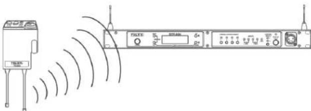
The RTS Wireless Intercom System is vertically polarized. This means both the transmitting and receiving antennas should operate in the vertical position.
natural_image
Line drawing of a wireless network device with signal waves and external components (no text or symbols)FIGURE 12. Vertically Polarized Antennas
Distance between Antennas
The distance between the base station's receive and transmit antennas is not adjustable when the antennas are connected directly on the back of the unit.
The antennas can be remotely mounted for a better signal path. An RTS coax assembly with remote antennas may be required. See “Accessory” section for ordering information.
NOTE: If your base station is to be located in a shielded rack mount enclosure or other poor RF locations, you must remotely mount the 1/2-wave antennas with coax assemblies. See “Accessories and Replacement Parts, for remote mounting hardware.
Antenna Placement
Proper antenna placement probably has the most effect on your RTS Wireless Intercom System's overall performance. The following suggestions result in optimum performance.
Proper placement of the beltpack can be critical. The antennas should be in the open. Bending the antennas up and placing the beltpack in a pocket, etc., reduces the system's distance. The unit should be worn on the belt with both antennas vertical for best operating range and performance.

FIGURE 13. Proper Dressing of the Antenna
Keep the distance between the base station and the beltpacks as short as possible. The greater the distance, the weaker the signal. Make sure the “signal paths” between the base station and beltpacks are unobstructed. You should be able to visibly locate the base station antennas at all times for best performance.

FIGURE 14. Distance Between Base Station and Beltpack

natural_image
Diagram showing two electronic devices connected via wireless signal waves to a network device (no text or symbols present)FIGURE 15. Keeping Site Clear to Antenna
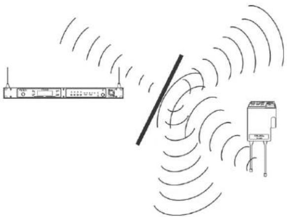
Attempting to operate the wireless intercom system through or around walls, ceilings, metal objects, etc. reduces system range and performance.
natural_image
Diagram showing wireless signal transmission between a network device and a sensor device (no text or symbols present)FIGURE 16. Operating System Near Obstructions
IMPORTANT: DO NOT mount the base station 1/2-wave antennas on or next to: metal, such as beams; walls with metal studs; or equipment racks, etc. This also applies to antennas assembled directly to the Base Station. Mounting antennas near metal detunes the antennas, which can result in noise or loss of RF signal at the Base Station. See Figure 17.
-
Placing the BTR on top of a shelf or equipment rack unobstructed without remoting the antennas is OK.
-
Placing BTRs in a shelf or equipment rack and using remote antennas is OK.
-
Placing BTRs in a shelf or equipment rack with the antennas mounted on the back of the BTR or the side of the rack is BAD.

natural_image
Line drawing of a server rack unit with multiple ports and indicator lights (no text or symbols)1

natural_image
Line drawing of an electrical control cabinet with multiple panel switches and buttons (no text or labels)2

natural_image
Front view diagram of a server rack unit with multiple ports and control panels (no text or labels)3
FIGURE 17. Antenna Placement
Improving Reception and Increasing Range
Keeping the distance from the base station and beltpack as short and unobstructed as possible produces the most reliable antenna performance.
The base station is supplied with two (2) antennas. This provides satisfactory system performance in most applications. System range can be enhanced by remotely mounting the 1/2-wave antennas. The 1/2-wave antennas are ground plane independent, so a ground plane is not required for good performance.
BTR-80N
Operation
This section discusses the operation and features of the BTR-80N base station, opening with base operation and quick system setup. It then discusses basic interfacing and setup of a base station, then ends with the connection of multiple base stations and discussion of the links between them.
Basic Operational Description
The BTR-80N narrow band wireless intercom system offers the most comprehensive, user-friendly, and versatile set of features available in wireless intercom systems anywhere in the world.
The base station accommodates up to four (4) full-duplex TR-80N or TR-82N beltpacks, and can be used with an unlimited number of beltpacks in push-to-TX (half-duplex) operation. In push-to-TX mode, the unit provides a First On Latch Out feature which allows only one beltpack transmitter to be active at a time when multiple users are on a single base receive channel.
The base station, via the beltpacks or it's local headset, allows communications with other wireless or wired users. The 2-wire and 4-wire intercoms may even be used at the same time. The wired audio interfaces to the base are:
• 2-Wire (Telex, RTS, Clear-Com) - 2 intercom channels
• 4-Wire - 2 audio channels
• Auxiliary (both input and output)
• SA (Stage Announce) (output)
- WTA (Wireless Talk-Around)/ 2 channels of private 2-wire intercom among TR-80N and TR-82N beltpacks
- Local base station headset
The base station also features:
- A relay closure activated when the SA button is pressed at any beltpack
- Four (4) easily accessible portable connect buttons on the front panel. Use the buttons to turn off the audio from any of the four (4) base receivers while at the same time killing the talk/transmitter at the associated beltpack
- 36 engineering selected, intermodulation avoiding, factory-defined groups
- The ability for users to enter frequencies of their own via 12 user-defined groups
System Quick Start
The following is a list to quickly get a base station and beltpacks operating.
- Unpack the base.
- Connect the power cord and antennas.
- Connect the base to audio interfaces, such as: 2-wire, 4-wire, SA, Auxiliary, or local headset.
- Press and hold MENU while powering up the base station.
-
When the base station displays FACTORY SETUP, release MENU.
-
Unpack the beltpacks.
-
Press MENU while powering up the beltpack(s).
-
Using the UP and DOWN arrow buttons, change the beltpack channel to an unoccupied receive channel on the base station.
-
Press SET twice to set channel and group. The base should now display the audio channel of the beltpack and a battery symbol appears shortly.
-
Plug a headset into each beltpack.
-
Adjust the microphone gain in the software menu so the overmodulation light flashes only on some of the words at normal speech levels.

FIGURE 18. BTR-80N Rear View
Transmit and Receive Antennas
The TNC transmit jack and receiver jack are both labeled on the rear of the unit. The base station comes with two (2) 1/2-wave antennas. Always match the color dot on the rear panel of the base station with the colored band on the antenna.
2-Wire Intercom Ports
The base station has the ability to interface with two (2) 2-wire external audio intercom systems. These XLR jacks are designated intercom 1 and 2 on the rear panel.
They accept Telex, RTS, and Clear-Com types of intercom systems. The pinouts of these standard types of intercom are shown in Figure 19.
The base station does not require wet intercom lines for operation. Wet intercom lines are those with D.C. voltages on them for powering 2-wire devices. The base loops through wet intercom lines with currents up to two (2) Amps.
WARNING: Do not loop through more than two (2) Amps of current. Damage to the base station may result.
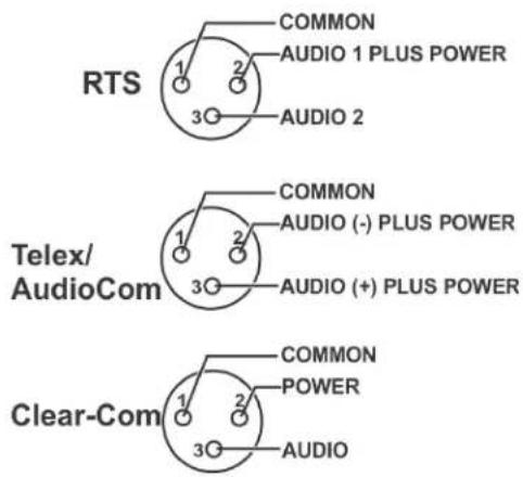
FIGURE 19. Pinouts of RTS, Telex, and Clear-Com Intercoms

FIGURE 20. Loop-through of two base stations connected with Telex/Audiocom or Clear-Com Intercoms
If multiple base stations are connected via 2 -wire intercom and no 2-wire power supply is involved to terminate the 2-wire, then termination plugs for the type of 2-wire system used must be at one end of each intercom line.
Since RTS-TW carries both channels of audio on one (1) cable, the four (4) intercom XLR connectors are connected in parallel when RTS is selected. Thus any one (1) of the four (4) intercom XLRs may be used for RTS input. Looping through of the audio, shown in Figure 21, may also be accomplished via any of the rear panel XLRs when in FTS mode. For a description of how to set up the 2-wire ports, refer to Intercom Settings in this section. The 2-wire intercom may be used at the same time as the 4-wire intercom.
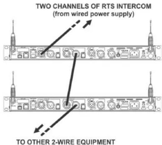
FIGURE 21. Loop-through of two base stations connected with RTS Intercoms

FIGURE 22. BTR-80N Rear View
4-Wire Intercom Ports
The BTR-80N can connect to two (2) 4-wire audio intercom systems. These 6-pin modular jacks (RJ-11) are designated 4-wire under intercom 1 and 2 titles on the rear panel. (See Figure 22). The jack's pinout is shown in Figure 23.
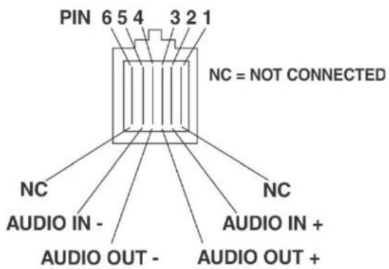
FIGURE 23. Pinout of the 4-Wire Jack
The 4-wire intercom may be used at the same time as the 2-wire intercom.
Auxiliary Input/Output
The auxiliary input jack is a combination jack. It accepts either a 3-pin XLR or a 1/4" (6.3mm) plug. The expected input is a balanced line level input. Shown in Figure 24, the XLR plug and 1/4" plug are wired in parallel
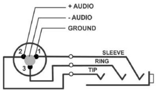
FIGURE 24. Auxiliary Input XLR and 6.3mm Jack Pinouts
The auxiliary output jack is a 3-pin XLR jack. It produces a line level balanced output. Please refer to Figure 25.
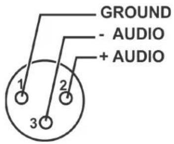
FIGURE 25. Pinout of the Auxiliary Output Jack
The auxiliary input/output can be set to local, global, or off. (See the Aux Settings menu in the base). The output level is configured in the software.
- Local Aux Input - The input audio is only heard at the base station's local headset and beltpacks.
- Local Aux Output - The output audio is only heard at the base station's local headset and beltpacks.
- Global Aux Input - The input audio is heard at the base station's local headset and beltpacks and is placed on the 2-wire/4-wire intercom.
- Global Aux Output - The output audio is heard at the base station's local headset and beltpacks and is placed on the 2-wire/4-wire intercom.
• Off - the auxiliary input and output is off.

FIGURE 26. BTR-80N Rear View
Base Station Link
This pair of RJ-45 jacks allow the passage of WTA, WTA termination control voltage, and CAN bus data between multiple base stations. Up to eight (8) base stations may be connected with the base station link. If just using WTA between bases, up to 16 base stations can be connected together. The pinout of the IN jack and OUT jack may be seen in Figure 27 and Figure 28
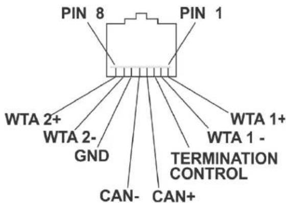
FIGURE 27. Base Station Link IN RJ-45 Jack Pinout

FIGURE 28. Base Station Link OUT RJ-45 Jack Pinout
Stage Announce (SA)/Relay
The Stage Announce 3-pin XLR connector (see Figure 26) is where audio exits the base when a beltpack user presses the SA button. The pinout of the plug connector is shown in Figure 29.

FIGURE 29. Stage Announce Pinouts
The stage announce output is balanced audio at line level. The output level is configured in the software.
A relay contact closure also activates when a beltpack user presses the SA button. The contacts are normally open (N.O.). The relay schematic is shown in Figure 30. The rating of the relay is 1 Amp at 24 volts AC or DC maximum.

flowchart
graph TD
    A["Pin 1"] --> B((Loop))
    C["Pin 2"] --> B
    B --> D["Output"]
    style B fill:#f9f,stroke:#333
FIGURE 30. Relay Output Schematic (Normally Open)
A Phoenix type connector (supplied) plugs into the relay contact port on the rear of the base station. This connector provides a screw-type closure for an easy connection to wires. See Figure 31.

FIGURE 31. Screw Terminal Adapter

FIGURE 32. BTR-80N Base Station Link Jack and Program Jack
Base Station Link Jack
WTA 1 and WTA 2 in the BTR-80N are two (2) independent 2-wire intercom channels. Up to 16 base stations may be connected together to share WTA audio. Do not confuse WTA audio with CAN bus data, as only eight (8) bases may be connected to share CAN bus data. Not only does the WTA Link cable pass both channels of WTA audio, it passes a logic level so the 1st base station in the chain is the only one providing a termination of the WTA intercom channels. Care must be taken to connect cables between base stations from the OUT of base one (1) to the IN of base two (2) and so forth. If the WTA link cable is passed from OUT to OUT or IN to IN, the WTA audio may terminate in multiple places and cause the WTA audio level to be greatly reduced.
The base station link jacks can interface with other base stations via two (2) different types of cables:
- Base Link Cable (BLC)
- Straight through cable. Passes CAN data, WTA audio, and WTA termination signal.
• CAN Bus Termination Cable (CTC)
- Passes WTA audio and WTA termination signal, but does not pass CAN data. Acts as a termination of the CAN networks on either side of it.
Detailed information on the pinout and operation of these cables can be found in "Connection of Multiple Base Stations with the Link Cables" on page 40.
Program Jack
This jack is only used for updating the internal software of the base station. It is typically used only by the manufacturer and service centers.
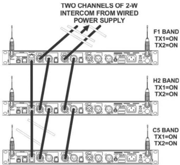
FIGURE 33. Multiple Base Stations Connected via 2-Wire Cables Sharing WTA Audio

FIGURE 34. BTR-80N - Front Panel
Powering the Base Station
The base station may be powered two (2) different ways:
- Line power at the IEC receptacle. Accepts 100–240VAC, 1A max., 50 or 60Hz.
- 12–15VDC Power. Accepts a 5.5mm by 2.5mm screw on plug. Source must supply at least 3.5 Amps.
To power on the base station, do the following:
Press the POWER button located on the far left of the base station front panel.
To power off the base station, do the following:
Press and hold the POWER button.
Both line power and DC power can connect to the base station at the same time. If AC line voltage drops, the base draws power from the DC input automatically. When the AC line power is restored, the base automatically switches back to AC power. There is no interruption in the base operation during these transitions.
CAUTION: Do not power up a base station within three (3) seconds of the unit being turned off. Voltages within the unit need time to drop below a threshold. If powered up within the above time, the unit may boot as the wrong frequency band.
WARNING: Even with the unit powered down via the power switch, some circuits within the base remain energized. To completely remove power to the unit, disconnect the power cord.
Start Up Screen
When the BTR-80N powers up, the first screen displayed is the Start Up splash screen. It displays for about three (3) seconds. This screen contains both the software version number and band ID of the base. Figure 35 shows a screen indicating software version sb4010C and a F1 band unit.

FIGURE 35. Start Up Screen
After three (3) seconds the status screen appears.
NOTE: A complete screen flowchart of the base station is available in Additional Resources.
Status Screen
The Status screen is the main information screen of the base station. It displays a number of system items:
- Frequency Group
• Band of Base Station
• Mode of Base Station
• Transmitter 1 Power Setting
• Transmitter 2 Power Setting - Beltpack Current Activity
- Battery Life
- Base Receiver Status

FIGURE 36. Status Screen
RSSI Screen
RSSI stands for Received Signal Strength Indicator. This screen displays the detected signal strength of each of the four (4) receivers in the base.

FIGURE 37. RSSI Screen
The following are the approximate receive levels indicated by the bars after each receiver.
OFF = Displayed as receiver status when receiver is deselected via the front panel

bar
| Voltage Range | Count | |---|---| | <0.2uV | 0 bar | | <0.6uV | 1 bar | | ~2uV | 2 bar | | ~6uV | 3 bar | | ~10uV | 4 bar | | >20uV | 5 bar |FIGURE 38. Receive levels indicated by bars.
If no beltpacks are operating, an RSSI level of two (2) bars or above may indicate interference on that frequency. A different receive channel should be selected.
To access the RSSI screen, do the following:
From the status screen, press and hold MENU for two (2) seconds.
To exit the RSSI screen, do the following:
press MENU to arrive back at the status screen.
Group/Channel Select Screen
The group/channel, group/frequency, and frequency edit screens allow the user to set the frequencies of the base station. Each screen has a slightly different way to set frequencies.

FIGURE 39. Group/Channel Screen
The Group/Channel screen displays the group number and the channel assigned to each of the four (4) receivers. Each channel is a unique base receive frequency. The frequencies of factory - defined groups 1A to 18 can only be selected from a set number of predetermined channels.
User-defined groups 18u to 30u may be changed by the user to any frequency within range of the base.
Group/Channel Screen
To select the group and channel, do the following:
- From the status screen, press MENU.
GP_CH select, Base Main, Intercom Settings, and Aux Settings appear in the main selection screen.
-
Using the UP/DOWN arrow buttons, select GP_CH Select.
-
Press SET.
The Group/Channel Select screen appears. The Group flashes.
-
Using the UP/DOWN arrows, select a group.
-
Press SET.
The change is accepted and Channel starts to flash.
-
Using the UP/DOWN arrows, select a channel.
-
Press SET.
The change is accepted and the focus moves to the next receiver. After the last receiver channel is set, the unit changes to the group and channels selected, and then returns to the main screen.
Group/Frequency Screen
The Group Frequency screen displays the group number and frequencies assigned to each of the four (4) receivers. It is just like the Group/Channel screen except the receive channels are displayed as frequencies. Also, the transmit frequencies are displayed.

FIGURE 40. Group/Frequencies Screen
To select the group and frequency, do the following:
- From the status screen, press MENU.
GP_CH select, Base Main, Intercom Settings, and Aux Settings appear in the main selection screen.
-
Using the UP/DOWN arrow buttons, select GP_CH Select.
-
Press MENU again in the Group/Channel screen.
The Group/Frequency Select screen appears. The Group flashes.
-
Using the UP/DOWN arrows, select a group.
-
Press SET.
The change is accepted and Frequency starts to flash.
-
Using the UP/DOWN arrows, select a frequency for the channel.
-
Press SET.
The change is accepted and the focus moves to the next frequency. After the last receive frequency is set, the unit
displays the group and frequencies selected, and then returns to the main screen.
Frequency Edit (User-Defined Groups Only)
The Frequency Edit screen is similar to the Group Frequency Select screen, but allows the complete editing of each transmit and receive frequency.

FIGURE 41. Frequency Edit Screen
To edit the frequency screen, do the following:
-
From the status screen, press MENU. GP_CH select, Base Main, Intercom Settings, and Aux Settings appear in the main selection screen.
-
Using the UP/DOWN arrow buttons, select GP_CH Select.
-
Press the MENU button twice. The Frequency Edit screen appears. The Group flashes.
-
Using the UP/DOWN arrow buttons, select a frequency.
-
Press SET. The changes are accepted and the focus moves to the next transmitter. After transmitter 2 is set, the channel 1 receiver frequency begins to flash.
-
Using the UP/DOWN arrow buttons, select a frequency.
-
Press SET. The change is accepted and the focus moves to the next channel. After the last receive channel frequency is set, the unit sets itself to the frequencies and returns to the main selection screen.
NOTE: Press MENU at anytime and the unit changes to the group and frequencies selected.
Base Main Settings
Settings contained in the base main menu are the following:
- Local headset microphone gain
- Local headset volume
• Transmit power level
• Squelch setting for each receiver
• Stage Announce (SA) audio level setting
• Receive antenna bias T power - Base Number...Master or Servant

FIGURE 42. Local Headset Area of Front Panel
TALK Button
To enable the audio path from the headset microphone, do the following:
Press the TALK button. The talk light activates when the TALK button is active.
This light has two (2) functions:
Green - Indicates activation of the TALK button.
Red or flashing red - Indicates input audio too strong (Peak)
| Peak Light Microphone Gain | |
| Light flashes on loudest speech | Okay |
| Light flashes on all speech | Too high |
| Light never flashes on normal speech | Too low |
Channel Select Button
The Channel Select button selects the intercom channel for the local headset. Each press of the button cycles through the options: intercom one, intercom two, or both, and then back to intercom one (1). The LEDs above the button indicate what channel is currently connected to the local headset.
Local Headset Volume and Gain
The Local Headset Volume and Microphone Gain are set in the following software screen.
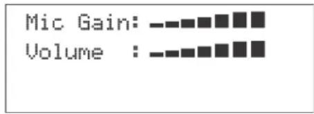
FIGURE 43. Microphone Gain/Volume
To access the microphone gain and volume level, do the following:
- From the status screen, press MENU.
- Using the UP/DOWN arrow buttons, select Base Main.
- Using the UP/DOWN arrow buttons, select Local Headset.
- Press SET. The microphone gain flashes.
- Using the UP/DOWN arrow buttons, adjust the gain.
NOTE: Each press of the button is about a 3dB step increase or decrease in gain.
-
Press SET. The volume flashes.
-
Using the UP/DOWN arrows, adjust the volume.
NOTE: Each press of the button is about a 3dB step increase or decrease in volume.
-
Press SET. The base menu selection menu screen appears.
-
Press MENU twice to go back to the status screen.
NOTE: The base defaults back to the status screen if no action is taken after five (5) minutes.
Base Transmitter Power
The base station has the following transmit power settings for both transmitters:
- Off
- 10mW
- 50mW (Default)
100mW
249mW
The user may also set which transmitter is on or off. The default is both transmitters on

FIGURE 44. TX Power
To access the transmit power settings, do the following:
- From the main status screen, press MENU.
- Using the UP/DOWN arrow buttons, select Base Main.
- Press SET.
- Using the UP/DOWN arrow buttons, select TX-Power.
- Press SET. The transmit power level starts flashing.
- Using the UP/DOWN arrow buttons, adjust the level.
- When finished, press SET. The transmitter's on/off indicators flash.
- Using the UP/DOWN arrows buttons, select ON or OFF.
- When finished, press SET. The Base Main select menu screen appears.
- Press MENU twice.
The base menu select menu screen appears.
NOTE: The base defaults back to the status screen if no action is taken after five (5) minutes.
Squelch Settings
Each of the four (4) receivers of the base station has four (4) adjustable squelch levels. These levels are equivalent to a SINAD level to open squelch for a receiver. The higher the squelch level number, the quieter the receiver is before it squelches; however, the RF range is slightly less than a receiver with a lower number.
$$ 0 0 = O P E N (f o r t e s t i n g o n l y, d o n o t u s e) $$
$$ 0 1 = 1 2 d B S I N A D $$
$$ 0 2 = 2 0 d B \text { SINAD (Default) } $$
$$ 0 3 = 2 4 d B S I N A D $$
CAUTION: Do not use Squelch Setting 00! A squelch level of 00 turns off all squelch gating. This can allow loud white noise into the audio of a base station if no transmitter is on the RF frequency or the portable select button is on. This setting is for test purposes only.

FIGURE 45. Squelch Setting
To set the squelch setting, do the following:
- From the status screen, press MENU.
- Using the UP/DOWN arrow buttons, select Base Main.
- Press SET.
-
Using the UP/DOWN arrow butts, select Squelch Settings.
-
Press SET.
The receiver 1 squelch setting starts flashing.
-
Using the UP/DOWN arrow buttons, adjust the setting.
-
When finished, press SET.
-
Repeat steps six (6) and seven (7) to set the remaining receivers.
-
When finished, press SET.
The Base Main selection menu appears.
- Press MENU twice.
The base menu select menu screen appears.
NOTE: The base defaults back to the status screen if no action is taken after five (5) minutes.
The base employs two (2) different types of squelches. A fast acting noise type squelch and a slower data squelch. For audio to be received by the base, both a good signal-to-noise audio signal (with a noise threshold set via the user squelch settings above) and a valid data stream must be detected.
Stage Announce Level
The Stage Announce software option allows the user to adjust the audio output level of the rear panel stage announce jack.

FIGURE 46. Stage Announce
To set the stage announce level, do the following:
-
From the status screen, press MENU.
-
Using the UP/DOWN arrow buttons, select Base Main.
-
Press SET.
-
Using the UP/DOWN arrow buttons, select MORE...
-
Press the DOWN arrow button.
The stage announce level flashes.
- Using the UP/DOWN arrow buttons, adjust the setting.
NOTE: Each press of the button is a 6dB step increase or decrease of volume.
-
When finished, press SET.
-
Step through the other settings in the screen by pressing SET.
After the last option on the screen, the base main selection menu appears.
- Press MENU twice to go back to the status screen.
NOTE: The base defaults back to the status screen if no action is taken after five (5) minutes.
Antenna Power
Antenna Power can be enabled or disabled. If antenna power is enabled, 9VDC is placed on the center pin of the receive antenna. The purpose of this voltage is to power in-line low noise amplifiers on the receive coaxial cable in order to compensate for excessive RF signal loss due to long cable runs.
Specifications of the power on the antenna jack:
Options: On/Off (Off=Default)
Voltage: 9VDC
Current: 100mA max.
Protection: Current is limited to 100mA
Base can withstand a continuous short to ground without damage.

FIGURE 47. Antenna Power
To enable or disable the antenna power, do the following:
- From the status screen, press MENU.
- Using the UP/DOWN arrow buttons, select Base Main.
- Press SET.
- Using the UP/DOWN arrow buttons, select MORE...
- Press the DOWN arrow button.
The stage announce level starts flashing.
- Press SET until Antenna Power flashes.
- Using the UP/DOWN arrows, adjust the setting.
- When finished, press SET.
- Step through the other settings in the screen by pressing SET.
After the last option on the screen, the base main selection menu appears.
- Press MENU twice to go back to the status screen.
NOTE: The base defaults back to the status screen if no action is taken after five (5) minutes.
CAN Bus Number
The CAN Bus Number for a base station must be set only in multiple base station configuration and only if the operator wishes to have the following features shared among multiple base stations:
- First-On-Latch – Out of receiver channels (Push to transmit)
• Automatic beltpack TX power control
• Automatic beltpack user ID assignment - Beltpack TX and Talk shutdown via the base front panel
Table 1 lists valid base number settings. Please see "Connection of Multiple Base Stations with the Link Cables" on page 40.
TABLE 1. Valid Base Number Settings
| Base Number Function | |
| 01 Master | |
| 02 Servant | |
| 03 Servant | |
| 04 Servant | |
| 05 Servant | |
| 06 Servant | |
| 07 Servant | |
| 08 Servant | |
| 09 Unassigned (Default) | |

FIGURE 48. Base Number
To set the CAN bus number, do the following:
- From the status screen press MENU.
- Using the UP/DOWN arrow buttons select More...
- Press the DOWN arrow button.
- Press SET until the Base Number option flashes.
- Using the UP/DOWN arrow buttons, set the number.
- When finished, press SET.
- Step through the other settings in the screen by pressing SET.
After the last option on the screen, the base main selection menu appears. - Press MENU twice to go back to the status screen.
NOTE: The base defaults back to the status screen if no action is taken after five (5) minutes.
Intercom Settings
There are multiple parameters to set in the Intercom Setting menu:
• 2-wire intercom type: Telex, RTS, Clear-Com, Off
• Only intercom 1 active, only intercom 2 active, both
• 2-wire intercom input/output levels
• 4-wire intercom on/off
• 4-wire intercom input/output levels
2-Wire Intercom
The screens below show the progression of setting 2-wire parameters.

To adjust the 2-wire intercom settings, do the following:
- From the status screen, press the MENU button.
- Using the UP/DOWN arrow buttons, select Intercom Settings.
- Press SET.
- Using the UP /DOWN arrow buttons, select 2-W.
- Press SET.
The 2-wire intercom type flashes.
- Using the UP/DOWN arrow buttons, set the intercom type.
- When finished, press SET.
The intercom channel flashes.
NOTE: If off is selected, the 2-W/4-W menu options appear.
- Using the UP/DOWN arrow buttons, select the intercom setup—intercom 1, intercom 2, or both.
- Press SET.
The intercom input level flashes.
- Using the UP/DOWN arrow buttons, select the input level.
- When finished, press SET.
- Proceed through the intercom settings. Once finished, the screen display returns to the 2-W/4-W selection menu.
- Press MENU twice to go back to the status screen.
NOTE: The base defaults back to the status screen if no action is taken after five (5) minutes.
4-Wire Intercom
The screens below show the progression of setting 4-wire parameters.

flowchart
graph TD
    A["2W Intercom"] --> B["4W Intercom"]
    B --> C["4W IC1: On\n4W IC1 IN: -■■■■■■■■■■■■■■■■■■■■■■■■■■■■■■■■■■■■■■■■■■■■■■■■■■■■■■■■■■■■■■■■■■■■■■■■■■■■■■■■■■■■■■■■■■■■■■■■■■■■<br>    C --> D[4W IC2: On\n4W IC2 IN: -■■■■■■■-□□□□□□□□□□□□□□□□□□□□□□□□□□□□□□□□□□□□□□□□□□□□□□□□□□□□□□□□□□□□□□□□□□□□□□□□□□□□□□□□□□□□□□□□□□□□□□□□□□□□○<br>    D --> E[4W IC2 OUT: -■■■■■-□□□□□□□□□□□□□□□□□□□□□□□□□□□□□□□□□□<br>    E --> F[4W IC2 OUT: -■■■-0<br>    E --> G[4W IC2 OUT: -0<br>    E --> H[4W IC2 OUT: -0<br>    E --> I[4W IC2 OUT: -0<br>    E --> J[4W IC2 OUT: -0<br>    E --> K[4W IC2 OUT: -0<br>    E --> L[4W IC2 OUT: -0<br>    E --> M[4W IC2 OUT: -0<br>    E --> N[4W IC2 OUT: -0<br>    E --> O[4W IC2 OUT: -0<br>    E --> P[4W IC2 OUT: -0<br>    E --> Q[4W IC2 OUT: -0<br>    E --> R[4W IC2 OUT: -0<br>    E --> S[4W IC2 OUT: -0<br>    E --> T[4W IC2 OUT: -0<br>    E --> U[4W IC2 OUT: -0<br>    E --> V[4W IC2 OUT: -0<br>    E --> W[4W IC2 OUT: -0<br>    E --> X[4W IC2 OUT: -0<br>    E --> Y[4W IC2 OUT: -0<br>    E --> Z[4W IC2 OUT: -0<br>    E --> AA[4W IC2 OUT: -0<br>    E --> AB[4W IC2 OUT: -0<br>    E --> AC[4W IC2 OUT: -0<br>    E --> AD[4W IC2 OUT: -0<br>    E --> AE[4W IC2 OUT: -0<br>    E --> AF[4W IC2 OUT: -0<br>    E --> AG[4W IC2 OUT: -0<br>    E --> AH[4W IC2 OUT: -0<br>    E --> AI[4W IC2 OUT: -0<br>    E --> AJ[4W IC2 OUT: -0<br>    E --> AK[4W IC2 OUT: -0<br>    E --> AL[4W IC2 OUT: -0<br>    E --> AM[4W IC2 OUT: -0<br>    E --> AN[4W IC2 OUT: -0<br>    E --> AO[4W IC2 OUT: -0<br>    E --> AP[4W IC2 OUT: -0<br>    E --> AQ[4W IC2 OUT: -0<br>    E --> AR[4W IC2 OUT: -0<br>    E --> AS[4W IC2 OUT: -0<br>    E --> AT[4W IC2 OUT: -0<br>    E --> AU[4W IC2 OUT: -0<br>    E --> AV[4W IC2 OUT: -0<br>    E --> AW[4W IC2 OUT: -0<br>    E --> AX[4W IC2 OUT: -0<br>    E --> AY[4W IC2 OUT: -0<br>    E --> AZ[4W IC2 OUT: -0<br>    E --> BA[4W IC2 OUT: -0<br>    E --> BB[4W IC2 OUT: -0<br>    E --> BC[4W IC2 OUT: -0<br>    E --> BD[4W IC2 OUT: -0<br>    E --> BE[4W IC2 OUT: -0<br>    E --> BF[4W IC2 OUT: -0<br>    E --> BG[4W IC2 OUT: -0<br>    E --> BH[4W IC2 OUT: -0<br>    E --> BI[4W IC2 OUT: -0<br>    E --> BJ[4W IC2 OUT: -0<br>    E --> BK[4W IC2 OUT: -0<br>    E --> BL[4W IC2 OUT: -0<br>    E --> BM[4W IC2 OUT: -0<br>    E --> BN[4W IC2 OUT: -0<br>    E --> BO[4W IC2 OUT: -0<br>    E --> BP[4W IC2 OUT: -0<br>    E --> BQ[4W IC2 OUT: -0<br>    E --> BN[4W IC2 OUT: -0<br>    E --> BO[4W IC2 OUT: -0<br>    E --> BN[4W IC2 OUT: -0<br>    E --> BO[4W IC2 OUT: -0<br>    E --> BOB[4W IC2 OUT: -0<br>    E --> BOB[BQ"]
    BQ]
FIGURE 50. 4-Wire Intercoms
To adjust the 4-wire intercom settings, do the following:
- From the status screen, press the MENU button.
- Using the UP/DOWN arrow buttons, select Intercom Settings.
- Press SET.
- Using the UP /DOWN arrow buttons, select 4-W.
- Press SET. The intercom one 4-wire on/off selection flashes.
- Using the UP/DOWN arrow buttons, select on or off.
- When finished, press SET. The intercom input level flashes.
NOTE: If off is selected, the screen skips to the intercom two screen.
- Using the UP/DOWN arrow buttons, select the intercom setup—intercom 1, intercom 2, or both.
-
Press SET. The intercom input level flashes.
-
Using the UP/DOWN arrow buttons, select the input level.
-
When finished, press SET.
- Proceed through the intercom output settings in a similar manner. Once finished, the intercom two 4-wire on/off selection flashes.
- Repeat steps 6-12 for intercom two. Once finished, the screen display returns to the 2-W/4-W selection menu.
- Press MENU twice to return to the status screen.
NOTE: The base defaults back to the status screen if no action is taken after five (5) minutes.
Auxiliary Settings
The parameters to configure in the auxiliary setting menu are as follows:
• Intercom 1 Auxiliary mode: Local, Global, or Off
• Intercom 2 Auxiliary mode: Local, Global, or Off
• Auxiliary input/output levels
The auxiliary setting for Local, Global, and Off are defined as the following:
Local Any audio placed into the auxiliary input port is routed only to the base's local headset and beltpack(s). Any audio heard out of the auxiliary output port is only from the base's local headset and beltpack(s).
Global Any audio placed into the auxiliary input port is routed not only to the base's local headset and beltpack, but also to any wired 2-wire or 4-wire system connected to the base station. Any audio heard from the auxiliary output is not only from the base's local headset and beltpack, but also from any wired 2-wire or 4-wire system connected to the base station.
Off The auxiliary input and output for the intercom channels is disabled.

FIGURE 51. Auxiliary Input/Output
To configure the auxiliary settings, do the following:
- From the status screen, press the MENU button.
- Using the UP/DOWN arrow buttons, select Aux Settings.
- Press SET. The Intercom 1 auxiliary local, global, or off selections start flashing.
- Using the UP/DOWN arrow buttons, select the option you desire.
- When finished, press SET.
- Repeat steps 1 through 5 for Intercom 2.
- When finished, press SET. The auxiliary input level flashes. This level is applied to both intercom channels.
- Using the UP/DOWN arrow buttons, set the input level.
- When finished, press SET. The auxiliary output level flashes.
- Using the UP/DOWN arrow buttons, set the output level.
- When finished, press SET.
- Press MENU twice to go back to the status screen.
NOTE: The base defaults back to the status screen if no action is taken after five (5) minutes.
ClearScan
When ClearScan activates, the base shuts down its transmitters and begins scanning receive frequencies. The frequencies scanned are those in its factory-defined groups and any user-defined groups with at least one (1) frequency defined. The result is a screen like the one shown in Figure 52. The scan groups appear in order from the highest number of clear receive channels available to the least number of clear channels available.
To start ClearScan, do the following:
Press and hold MENU + SET for three (3) seconds.
NOTE: This process can take up to 12 seconds to complete. It depends on how many user-defined groups are configured. The more groups, the longer the scan takes.
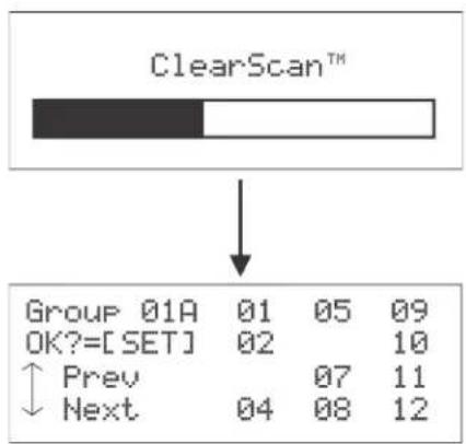
flowchart
graph TD
    A["ClearScan™"] --> B["Group 01A 01 05 09"]
    A --> C["OK?=[SET"] 02 10]
    C --> D["Prev 07 11"]
    C --> E["Next 04 08 12"]
FIGURE 52. Clear Scan Results Screen
NOTE: The base is not set to the displayed ClearScan result if the user presses the MENU button to abort.
Lockout
Lockout is used to keep a user from changing any options at the base station, except local headset microphone gain and volume.
To enable Lockout, do the following:
Press and hold UP+DOWN for two (2) seconds to lock or unlock the base station. A padlock appears on the status screen if the base is locked out.
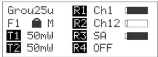
FIGURE 53. Status Screen with Lockout Active
Copy
Copy allows the user to select a factory-defined group and copy it to a user-programmed group. This allows a user to edit the group if desired.

FIGURE 54. Copy Screen
To use Copy, do the following:
Press and hold the SET+DOWN buttons for 2 seconds in the group/channel select screen (see Figure 54).
1st Use Defaults
1st Use Defaults is used to set the base station to Group 01A, channels 1, 2, 3, 4, and RETAIN any user-defined groups in memory. It sets the unit to factory-defined parameters.
To set the base station to 1st Use Defaults, do the following:
- Press and hold the MENU button while turning on the base station.
- When Factory Setup displays on the screen, release MENU.
Factory Default
Factory Default is used to set the base station to Group 01A, channels 1, 2, 3, 4, and ERASES any user-defined groups in memory. it sets the unit to factory-defined parameters.
To set the base station to Factory Default, do the following:
Press and hold MENU + SET + UP+ DOWN for two (2) seconds.
The screen in Figure 55 displays before the unit reboots.
...FACTORY SETUP...
FIGURE 55. FACTORY SETUP Display
Connection of Multiple Base Stations with the Link Cables
This section discusses various configurations of multiple base stations using link cables. Multiple base stations may be connected via standard 2-wire and 4-wire intercoms without additional link cables between them. They still transmit and receive intercom 1 and intercom 2 audio normally from the beltpacks.
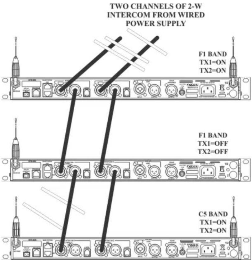
FIGURE 56. Multiple base stations with only 2-wire intercom channels 1 and 2 connected between them
However, by connecting multiple bases together via link cables, in addition to any 2-wire or 4-wire audio connections in use, the feature set of a single base becomes available to the whole system. This feature set also includes base stations that have their transmitters off in order to conserve RF spectrum.
- Beltpack Talk shutdown via the base front panel extended to base stations with their TXs off (when beltpacks are in push-to-talk mode).
These features are:
- (WTA) Wireless talk-around channels 1 and 2 shared between base stations.
- First-On-Latch-Out of beltpacks extended to base stations with their TXs off (when beltpacks are in push-to-transmit mode).
- Automatic beltpack TX power control extended to base station with their TXs off.
- Automatic beltpack user ID assignment extending to base stations with their TXs off.
- Beltpack TX and Talk shutdown via the base front panel extended to base stations with their TXs off (when beltpacks are in push-to-transmit mode).
Before presenting the configurations, we believe an explanation of RF data links plus master and servant base stations helps in understanding the multiple base arrangements.
Over-the-Air Data Links
There are two (2) RF data communication links within a BTR-80N system.
- Beltpack-to-base conveys:
- Current button(s) selected
- Battery level
- Beltpack ID set confirmation
- Base-to-beltpack conveys
- Beltpack User ID
- Beltpack TX power level
- Beltpack TX and/or Talk Shutdown
- First-On-Latch-Out

Base-to-Beltpacks Data Link (2 Links, 1 for each base transmitter, but same data on both.)
Beltpack-to-Base Data Link (One for Each Beltpack)


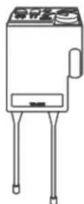

FIGURE 57. Base-To-Beltpack and Beltpack-To-Base RF Data Links
These two (2) data paths are intact when there is only one (1) base communicating to beltpacks. They are also intact when many base stations on different TX and RX frequencies are communicating to their beltpacks.
However, in a system with one (1) or more base stations with their transmitters off, the base-to-beltpack data link is lost for those bcltpacks
A wired data link is needed to communicate the base-to-beltpack information from the base stations with their transmitters off to the base with its transmitters on.

flowchart
graph TD
    A["Two channels of 2-W Intercom from wired power"] --> B["F1 BAND TX1=ON TX2=ON"]
    C["Beltpacks-to-Base Data Links"] --> D["F1 BAND TX1=OFF TX2=OFF"]
    E["Base-to-Beltpacks Data Links"] --> F["No Data Link From Base!"]
    G["No Data Link From Base!"] --> H["No Data Link From Base!"]
FIGURE 58. Three (3) base stations connected via 2-wire intercom only Two (2) bases have their transmitter off; one has its transmitters on
Master and Servant Base Stations
A master base station is one that the user has set its base number to 01(Master) and has its transmitters on. A master base conveys base-to-beltpack data to its beltpacks and via a base station link cable, relays the base-to-beltpack data from
base stations that have their base transmitters off. A master may support up to seven (7) additional base stations with their transmitters off.
IMPORTANT: There can be only one (1) master base station in a network of base stations.
A master base automatically sets a 09 (default) base to a unique 02 to 08 servant number. If a base is already a servant the master leaves it at that same number.
TABLE 2. Valid Base Number Settings
| Base Number Function | |
| 01 Master | |
| 02 Servant | |
| 03 Servant | |
| 04 Servant | |
| 05 Servant | |
| 06 Servant | |
| 07 Servant | |
| 08 Servant | |
| 09 Unassigned (Default) | |

FIGURE 59. Status screen of a master designated base station
NOTE: Any time base stations are changed to be a master base station, it must be power cycled for the change to take affect.
A servant base station is one that has its transmitters off and is connected to a master base. Since servant base stations have their transmitters off, base-to-beltpack information can only get to beltpacks via link cables connected to a master base station. There can be up to seven (7) servants working with one (1) master.

FIGURE 60. Status Screen of the Servant Base Station
A servant or master base is set via the Base Main menu screen in the base station.

flowchart
graph TD
    A["Group 1A R1 Ch1"] --> B["F1 M R2 Ch12"]
    B --> C["T1 50mW R3 SA"]
    C --> D["T2 50mW R4 OFF"]
    E["[MENU"]] --> F["GP_CH Select"]
    F --> G["Base Main"]
    G --> H["Intercom Settings"]
    H --> I["Aux Settings"]
    I --> J["[SET"]]
    J --> K["Local Headset"]
    K --> L["Tx Power"]
    L --> M["Squelch Settings"]
    M --> N["More..."]
    N --> O["[DOWN"]]
    O --> P["SA Level : Antenna Pur Off"]
    P --> Q["Base No : 01 Master"]
FIGURE 61. How to get to the master/servant selection screen
From the factory, base station are set to base number 09. This is an unassigned base. The base can be left as 09 if not in a linked system. It works as normal with all features.
If the unassigned base is connected to a master base station, the master automatically assign a valid, unique, servant ID to it the first time the networked system is powered-up.
The master base must always power-up after the servant bases in order to detect servant units to control. If all the units are on a common power strip, this is controlled by a built in delay on master base station. The master base station always boots slower than servant units.
CAN bus
A CAN (Controlled Area Network) bus is the data protocol used over the BTR-80N's base station link cable. This balanced protocol is a robust standard used the world over in high noise, extreme environments. It requires the use of 120 Ohm terminators at the beginning and end of a CAN bus network.
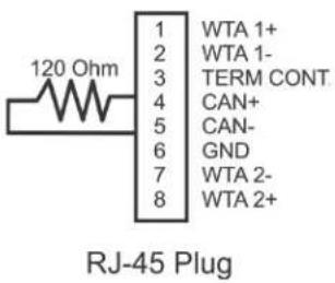
FIGURE 62. CAN Bus 120 Ohm termination (CAN-T) and base pin functions. Part Number: PRD000223002 (not supplied)
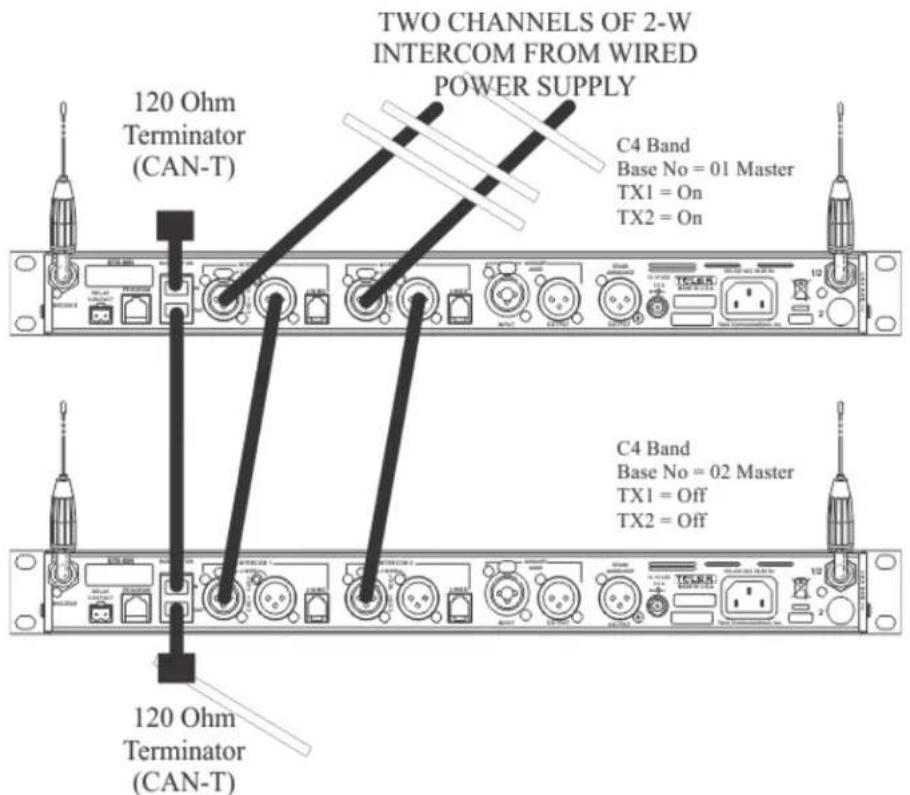
FIGURE 63. A base link cable connected system with terminators on both ends
Base Station Link Configurations
Multiple base station networks may be connected in different ways. Using the rear panel base station link jacks, a user has three (3) different connection options.
These options are:
• WTA (Wireless Talk-Around) Audio Only
- Bases connected via 2-wire and/or 4-wire audio links
- All bases share WTA audio
- They do NOT share CAN bus data
• WTA and a SINGLE CAN Bus Network
- Bases connected via 2-wire and/or 4-wire audio links
- All bases share WTA audio
- All bases are ON A SINGLE CAN BUS NETWORK
• WTA and Several CAN Bus Networks
- Bases connected via 2-wire and/or 4-wire audio links
- All bases share WTA audio
- There is MORE THAN ONE CAN BUS NETWORK
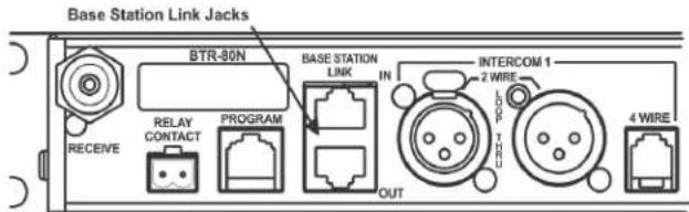
FIGURE 64. Base station link input and output jacks on the rear of the BTR-80N
Wireless Talk-Around Audio Only
These base stations are connected to share WTA channel 1 and WTA channel 2 audio but do not share the CAN bus data.
Link Overview
WTA 1 and WTA 2 in the BTR-80N arc two (2) independent 2-wire intercom channels. The WTA intercom channels are very similar to AudioCom types of intercom channels except they are dry and are meant to only pass audio between BTR-80N base stations.
Up to 16 base stations may be connected together with base link cables (BLC) depending on cable length and conductor size. The BLC passes both channels of WTA audio. It also passes a logic level so the 1st base station in the chain is the only one that provides a termination of the WTA intercom channels. This pin is labeled "TERM CONT" on the RJ-45 plug pinouts in this section.
Care must be taken to connect cables between base stations from the OUT of base one (1) to the IN of base two (2) and so forth, unit to unit.
If the WTA link cable passes from OUT to OUT or IN to IN, the WTA audio terminates in multiple places and causes the WTA audio levels to be greatly reduced/distorted.

FIGURE 65. BLC (Base Link Cable) and pin functions. Part Number PRD000223000 (Not Supplied)
If base stations are farther apart than the 12" (30.48cm) BLC, then 568-A or 568-B Ethernet cables of CAT-5E or above may be used to connect base stations up to 300 feet apart. These Ethernet cables contain four (4) twisted pairs like the BLC cable.

FIGURE 66. Multiple base stations connected via 2-wire audio cable and WTA through via BLCs
Do not set base stations to the base number 01 (Master), because CAN bus is connected to the other base stations with a BLC, as seen in Figure 66. If there are no masters on the CAN bus system, there is no activity on the CAN bus line and no need for terminations.
| IMPORTANT: The master base must always power-up after the servant bases in order to detect servant units to control. If all units are on a common power strip, this is controlled by a built in delay on the master base station. The master base station always boots slower than servant units. |
Setup
- Connect the power cords to the base stations.
IMPORTANT: Do not power up the base stations.
- Connect the transmit and receive antennas to the base stations.
NOTE: The color dots on the rear of the base should match the color rings of the antennas.
- Connect the main intercom audio channel(s) to the base stations.
NOTE: This may be 2-wire intercom. This could also be 4-wire intercom via a matrix type wired system.
- Connect the Base Link Cable between base stations.
NOTE: Verify the OUT of the first base station connects to the IN of second base station and follow the same connection pattern forward.
- Power-up all the base stations.
NOTE: The base stations should be set to all unique transmit and receive frequencies.
- Setup via the BTR-80N software menus the intercom, local headset, auxiliary, stage announce, etc. as detailed in BTR-80N Operation.
NOTE: All the base station numbers should be left as 09 (default).
- Turn on only one (1) beltpack.
NOTE: Try to keep the beltpack at least 6' (2 meters) away from the base's antennas.
- Set the beltpack on the appropriate group and channel for its base station. As each beltpack is set to its group and channel, an hourglass symbol appears on the base display in the location normally occupied by the battery symbol. A beltpack is assigned an ID number by the base in this time.
Finally, a normal battery symbol is displayed, indicated the beltpack has been assigned its ID number.
- Once the beltpack has an ID number, turn the beltpack off.
- Turn on the next beltpack.
- Repeat steps 8-9 for each additional beltpack.
- Power up the beltpacks.
WTA and a SINGLE CAN Bus Network
These base stations connect via 2-wire and/or 4-wire audio links and also by the Base Link Cable (BLC). The BLC cable passes WTA audio and CAN bus data information. The CAN bus connected base stations form a Network.
Link Overview
There are two (2) RF data communication links with a BTR-80N system. The beltpack-to-base links convey information such as current button(s) selected, battery level, etc. The base-to-beltpack links convey beltpack user ID, beltpack TX shutdown, beltpack talk shutdown, and other information.
The two (2) paths are intact when there is only one (1) base communicating to beltpacks and when many base stations on different TX and RX frequencies communicate to the beltpacks. However, when one (1) or more base stations with their transmitters off are connected to a base station with its transmitters on, the base-to-beltpack data link is lost for those beltpacks.
Care must be taken to connect cables between base stations from the Out of base one (1) to the IN of base two (2) and so forth. If the WTA link cable is passed from OUT to OUT or IN to IN, the WTA audio terminates in multiple places and causes the WTA levels to be greatly reduced/distorted.
| IMPORTANT: The master base must always power-up after the servant bases in order to detect servant units to control. If all units are on a common power strip, this is controlled by a built in delay on the master base station. The master base station always boots slower than servant units. |

FIGURE 67. Multiple base stations connected via 2-wire audio cable and WTA plus CAN through via BLCs
Setup
- Connect the power cords to the base stations.
IMPORTANT: Do not power up the base stations.
- Connect the transmit and receive antennas to the base stations.
NOTE: The color dots on the rear of the base should match the color rings of the antennas.
- Connect the main intercom audio channel(s) to the base stations.
NOTE: This may be 2-wire intercom. This could also be 4-wire intercom via a matrix type wired system.
- Connect the Base Link Cable between base stations.
NOTE: Verify the OUT of the first base station connects to the IN of second base station and follow the same connection pattern forward.
-
Place CAN bus termination plugs (CAN-T) at the beginning and end of the networked base stations.
-
Power-up all base stations.
-
Set all base stations to factory defaults via a four-button reset; MENU + SET + UP + DOWN.
- Power-down all the base stations.
- Power-up the first servant base station.
- Set the servant base station to all unique receive frequencies. The transmitters switch off automatically when the master base station takes control of them.
NOTE: Leave the base number at the default of 09.
- Setup via the BTR-80N software menus the intercom, local headset, auxiliary, stage announce, etc. as detailed in BTR-80N Operation.
NOTE: Leave the base station powered-up.
- Power-up the master base station.
- Set the master base station to all unique transmit frequencies.
- Setup via the BTR-80N software menus the intercoms, local headset, auxiliary, stage announce, etc., as detailed in BTR-80N Operation.
-
Set the master base station with its transmitters on to master base number 01.
-
Cycle the power of the master base while leaving the single servant base powered-up.
The master base, on boot, takes control of the servant base and assign it the base ID of 02 and turn its transmitters off. -
If there are additional servant base stations to configure, turn off the master base station.
-
Power-up the next servant base station.
-
Repeat steps 10-12 and 16-18 for each additional servant base.
NOTE:
- Always leave the previously assigned servant base stations powered-up when going on to the next base.
- The master base must always power up after the servant bases in order to detect servant units to control.
-
If all the units are on a common power strip, this is controlled by a built in delay in the master station. The master station always boots slower than servant units.
-
Repeat steps 9-19 for each additional network.
-
Turn on only one (1) beltpack.
NOTE: Try to keep the beltpack at least 6' (2 meters) away from the base's antennas.
-
Set the beltpack on the appropriate group and channel for its base station.
As each beltpack is set to its group and channel, an hourglass symbol appears on the base display in the location normally occupied by the battery symbol. A beltpack is assigned an ID number by the base in this time. Finally, a normal battery symbol displays, indicating the beltpack has been assigned its ID number. -
Once the beltpack has an ID number, turn the beltpack off.
-
Turn on the next beltpack.
-
Repeat steps 22-23 for each additional beltpack.
-
Power up the beltpacks.
WTA and Several CAN Bus Networks
These base stations may be connected via 2-wire and/or 4-wire audio links. They are also connected together via the Base Link Cable (BLC) and a new cable called the CAN Bus Termination Cable (CTC).
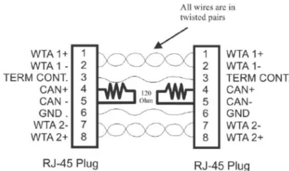
FIGURE 68. CAN Bus Termination Cable (CTC). Part number: PRD000223001 (Not Supplied)
Link Overview
Multiple masters on the same CAN bus are not allowed. The two different cables solve this issue. The BLC passes WTA audio and CAN bus data information. The CTC passes WTA audio and also functions to terminate the CAN network on either side of it. This allows many separate CAN networks to share the same two (2) WTA audio channels.
Care must be taken to connect cables between base stations from the OUT of base one (1) to the IN of base two (2) and so forth, unit to unit. If the WTA link cable passes from OUT to OUT or IN to IN, the WTA link cable terminates in multiple places and cause the WTA audio levels to be greatly reduced/distorted.
The master base must always power-up after the servant bases in order to detect servant units to control. If all units are on a common power strip, this is controlled by a built in delay in the master base station. The master base station always boots slower than servant units.
Setup
Setup is the same as the previous “WTA and a SINGLE CAN Bus Network” section, with the exception of a CTC cable between the two CAN networks.
- Connect the power cords to the base stations.
IMPORTANT: Do not power up the base stations.
- Connect the transmit and receive antennas to the base stations.
NOTE: The color dots on the rear of the base should match the color rings of the antennas.
- Connect the main intercom audio channel(s) to the base stations.
NOTE:
- This may be 2-wire intercom. This could also be 4-wire intercom via a matrix type wired system.
-
If using a party line to connect audio channels, the party line needs to be terminated by a connected PSU or a load XLR plug (P.N. TP-3 or TP-3R). See Figure 69.
-
Connect the (BLC) Base Link Cable between base stations within a CAN network.
NOTE: Verify the OUT of the first base station connects to the IN of second base station and follow the same connection pattern forward.
- Connect the CAN Bus Termination Cable (CTC) BETWEEN the CAN networks.
NOTE: Remember to connect from the OUT of the base station to the IN of the next base station. - Place CAN bus termination plugs (CAN-T) at the beginning and end of the networked base stations.
- Power-up all base stations.
- Set all base stations to factory defaults via a four-button reset; MENU + SET + UP + DOWN.
- Power-down all the base stations.
- For the first network of base stations, power-up the first servant base station.
- Set the servant base station to all unique frequencies. The transmitters switches OFF automatically when the master base takes control of them.
NOTE: Leave the base number at the default of 09.
- Setup via the BTR-80N software menus the intercoms, local headset, auxiliary, stage announce, etc., as detailed in BTR-80N Operation.
NOTE: Leave the servant base station powered-up.
- Power-up the master base station.
- Set the master base station to all unique transmit and receive frequencies.
- Setup via the BTR-80N software menus the intercoms, local headset, auxiliary, stage announce, etc., as detailed in BTR-80N Operation.
- Set the master base station with its transmitters on to the master base number 01.
- Cycle the power of the master base, while leaving the single servant base powered-up. The master base, on boot, takes control of the servant base and assign it the base ID of 02 and turn its transmitters off.
- If there are additional servant base stations to configure, turn off the master base station.
-
Power-up the next servant base station.
-
Repeat steps 11-13 and 17-18 for each additional servant base.
Always leave the previously assigned servant base stations powered-up when going on to the next base.
| IMPORTANT: The master base must always power-up after the servant bases in order to detect servant units to control. If all units are on a common power strip, this is controlled by a built in delay in the master base station. The master base station always boots slower than servant units. |
- Repeat steps 10-20 for each additional network.
- Turn on only one (1) beltpack on the first network system.
Try to keep the beltpack at least 6' (2 meters) away from the base's antennas.
- Set the beltpack on the appropriate group and channel for its base station.
As each beltpack is set to its group and channel, an hourglass symbol appears on the base display in the location normally occupied by the battery symbol. A beltpack is assigned an ID number by the base in this time. Finally, a normal battery symbol displays, indicating the beltpack has been assigned its ID number. - Once this first beltpack has an ID number, turn off the beltpack.
- Turn on the next beltpack.
- Repeat steps 23-24 for each additional beltpack.
- Power up the beltpacks.

FIGURE 69. Multiple base stations connected via 2-wire audio cable and two CAN Bus networks.
TR-80N/82N
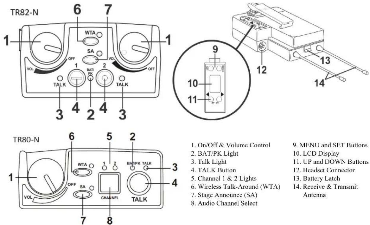
- On/Off & Volume Control
- BAT/PK Light
- Talk Light
- TALK Button
- Channel 1 & 2 Lights
- Wireless Talk-Around (WTA)
- Stage Announce (SA)
-
Audio Channel Select
-
MENU and SET Buttons
- LCD Display
- UP and DOWN Buttons
- Headset Connector
- Battery Latch
- Receive & Transmit Antenna
FIGURE 70. Controls and Connections
Basic Operational Description
The TR-80N/82N is a full-duplex (simultaneous talk and listen) beltpack. It works in conjunction with a BTR-80N base station. The beltpack allows a user, via a headset attached to the beltpack, to communicate with other wireless or wired users. Other base stations and/or wired systems connect to the beltpack's base station. The base station allows the audio path interconnections for the beltpack audio.
The TALK, WTA (wireless talk-around), and SA (stage announce) buttons on a beltpack turn the beltpack's microphone input on or off. They also select the audio paths for the beltpack's audio in the base.
System Quick Start
The following is a list to quickly get a base station and beltpacks operating.
- Unpack the base.
- Connect the power cord and antennas to the base.
- Connect the base to audio interfaces, such as: 2-wire, 4-wire, SA, Auxiliary, or local headset.
- Press and hold the MENU button, while powering-up the base station.
- When the base station displays...FACTORY SETUP..., release the MENU button.
- Press and hold the MENU button, while powering-up the beltpack(s).
- On the base station, use the UP and DOWN arrow buttons to change the channel to an unoccupied receive channel.
- Press SET twice to set channel and group. The base should now display the audio channel of the beltpack and a battery symbol appears shortly.
- Plug a headset into each beltpack.
- Adjust the software menu for microphone gain so the over modulation light flashes only on some of the words at normal speech levels.
Battery Installation
Ensure the On/Off volume control knob is turned off. Press down and hold down the battery release latch, then slide the battery pack about 1/8 inch back toward the latch until it stops. Lift the battery pack out. Replace batteries as follows:
- Open the battery pack by inserting fingernail and lifting

natural_image
Technical line drawing of a mechanical component with an inset showing a finger pressing a slot (no text or symbols)NOTE:
- Start loading at the end of the case where the strap is attached to the case.
-
Be sure strap goes under batteries.
-
Tuck end of strap under door when placing the battery cover back on the case.

natural_image
Technical line drawing of a mechanical assembly with no visible text or symbolsFIGURE 71. Battery Installation
- Pull battery strap to remove low or dead batteries.
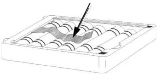
natural_image
Diagram of an abacus with a pointer indicating the number of beads (no text or symbols present)- Load new batteries following the polarity shown in the battery case.

WARNING:
Do not place an alkaline TR battery pack in any battery charger. Severe charger and battery pack damage may result.

FIGURE 72. TR-80N/82N Controls
Headset Connection
The Headset Connector is a XLR type connector. Four (4) or five (5) pin headset connectors may be installed in the unit. See the TR-80N/82N Controls and Connectors section for more information on the pinouts. A dynamic or electret headset microphone is automatically detected by the beltpack and a bias voltage supplied if needed.
Sidetone
Sidetone is the amount of the user's voice fed back to their headphone. The sidetone level in the beltpack and base station is fixed. It cannot be adjusted.
Antenna Connection
The beltpack comes with two detachable, screw type 1/4 wave antennas. Attach the two (2) antennas by screwing the antennas into the receptacles at the bottom of the beltpack. The color dot on the screw end of the antenna must match the color dot on the antenna receptacle.

FIGURE 73. TR-80N Top Panel Controls
On/Off and Volume Control
To turn the beltpack power on, do the following:
Rotate the On/Off Volume Control knob(s) CW.
To adjust the volume to the headset, do the following:
Rotate the On/Off Volume Control knob as required for a comfortable listening volume.
| Batt/PK LED Status | ||
| Battery Light | flashes on power up =Battery OK | |
| Light on continuously =Battery | Low | |
| Light does not flash/power on =Battery Dead | ||
| Over modulation | Light flashes on some speech =Gain OK | |
| Light flashes on all speech =Gain too high | ||
| Light never flashes on speech =Gain too low | ||
TALK Button
To enable the audio path from the headset microphone, do the following:
Press the TALK button.
The talk light activates when the TALK button is active. The TALK button has three (3) software selectable modes that can be seen via the LCD display of the beltpack.
To select the TALK button mode, do the following:
1. Press and hold SET while pressing the TALK button.
The current mode of the TALK button displays the first time the TALK button is hit. Pressing the TALK button a second time changes the mode of the button.
2. Release SET to accept the currently displayed setting.
| Selectable Modes: TALK | |
| tb off Talk disabled | |
| tb Ptt Push-to-talk | |
| tb I.At Push-to-latch |
Audio Channel Select Button
To select which intercom system the headset connects to, do the following:
- Press and hold SET while pressing the CHANNEL select button.
The current mode of the CHANNEL select button displays the first time the button is hit. Pressing the button a second time changes the mode of the button.
- Release SET to accept the currently displayed setting.
| Selectable Modes:Audio CHANNEL Button | 12 on | Channels 1 and 2 available |
| 1 on | Only channel 1 | |
| 2 on | Only channel 2 |
Stage Announce (SA)
To route audio from the beltpack directly to the stage announce connector on the back of the base station, do the following:
Press the SA button.
The base station's SA relay is also closed. The beltpack sidetone is lost as an indication that stage announce is activated. The other beltpacks and wired users do not hear this beltpack's audio when SA is pressed. The button is non-latching and activates the nearby red LED when pressed.
To enable or disable Stage Announce, do the following:
- Press and hold SET while pressing the SA button. The current mode of the SA button displays.
- Still holding SET, press the SA button again to turn SA on or off.
- Release SET to accept the displayed setting.
Wireless Talk Around (WTA)
To disconnect the beltpack audio from the wired intercom, auxiliary input/output, and the base station's local headset, do the following:
Press the WTA button.
Other beltpack users on that audio channel can hear the user as normal. The WTA button activates the nearby red LED as well as the appropriate talk LED when pressed.
To enable or disable Wireless Talk-Around options, do the following:
-
Press and hold SET while pressing the WTA button. The current WTA mode displays. Pressing WTA a second time changes modes. Available options are: Off, On, and Lon (Latch on).
-
Release SET to accept the displayed setting.
Groups and Channels
The first LCD screen the beltpack displays is the Group/Channel screen. This screen shows the currently selected receive group followed by the beltpack transmit channels.
To edit groups and channels, do the following:
- Push SET to edit the transmit channel. The channel number flashes.
- Using the UP/DOWN arrow buttons, select the desired transmit channel.
- Push SET to accept the channel. The receive group flashes.
- Using the UP/DOWN arrow buttons, select the desired receive group.
- Push SET to accept the receive group. The new group containing the selected channel is now set.
NOTE:
- To escape out of the editing without any changes, Press MENU.
- Factory group frequencies cannot be changed. User group frequencies (Group 19u to 30u) can be changed.
Transmit Frequency
The Transmit Frequency screen displays the beltpack transmitter frequency in MHz. The frequency is not changeable in factory-determined groups, but it is changeable in user-defined groups.
To edit the TX frequency (User Groups Only), do the following:
- Set the unit to the desired user-defined group and channels. See Groups and Channels Instructions. The menu structure in Figure 74 indicates how to get to the transmit frequency screen.
- Push SET to edit the TX frequency. The frequency flashes.
- Using the UP/DOWN arrow buttons, select the desired frequency. The frequency can be changed in 25 kHz steps.
- Push SET to place the unit on the new transmit frequency.
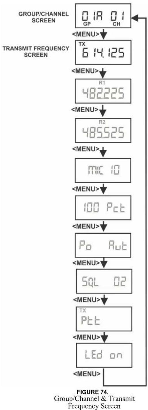
flowchart
graph TD
    A["0 18 0 1 GP CH"] --> B["<MENU>"]
    B --> C["TX 6 14.125"]
    C --> D["<MENU>"]
    D --> E["R1 482.225"]
    E --> F["<MENU>"]
    F --> G["R2 485.525"]
    G --> H["<MENU>"]
    H --> I["MIC 10"]
    I --> J["<MENU>"]
    J --> K["100 Pct"]
    K --> L["<MENU>"]
    L --> M["Po Rut"]
    M --> N["<MENU>"]
    N --> O["SQL 02"]
    O --> P["<MENU>"]
    P --> Q["TX Ptt"]
    Q --> R["<MENU>"]
    R --> S["LEd on"]
    S --> T["<MENU>"]
Receive Frequency
The Receive Frequency screen displays the beltpack receiver frequencies in MHz. The frequency cannot be changed in factory-defined groups, but can be changed in user-defined groups.
To edit the RX frequency (User Groups Only), do the following:
- Set the unit to the desired user-defined group and channels. See Groups and Channels Instructions. The menu structure in Figure 75 indicates how to get to the receive frequency screen.
- Push SET to edit the RX frequency. The frequency flashes.
- Using the UP/DOWN arrow buttons, select the desired frequency. The frequency can be changed in 25 kHz steps.
- Push SET to place the unit on the new receive frequency.
Microphone Gain
The Microphone Gain screen displays the beltpack microphone gain setting. There are 16 possible settings. The number zero (0) indicates minimum microphone gain, the number 15 is maximum. Each step is about three (3) dB.
To adjust the microphone gain, do the following:
- Push SET at the microphone gain screen. The number flashes.
- Using the UP/DOWN arrow buttons, select the desired gain.
- Push SET to place the unit at the indicated microphone gain.
Battery Display
The Battery Display screen indicates the current percentage of battery remaining.
Battery Percentages
100 Pct. = Fresh Battery
75 Pct. = 75% Life Left
50 Pct. = 50% Life Left
25 Pct. = 25% Life Left
10 Pct. = 10% Life Left. Low Battery Light
0 Pct. = Battery Dead. Unit will lose communication at any time
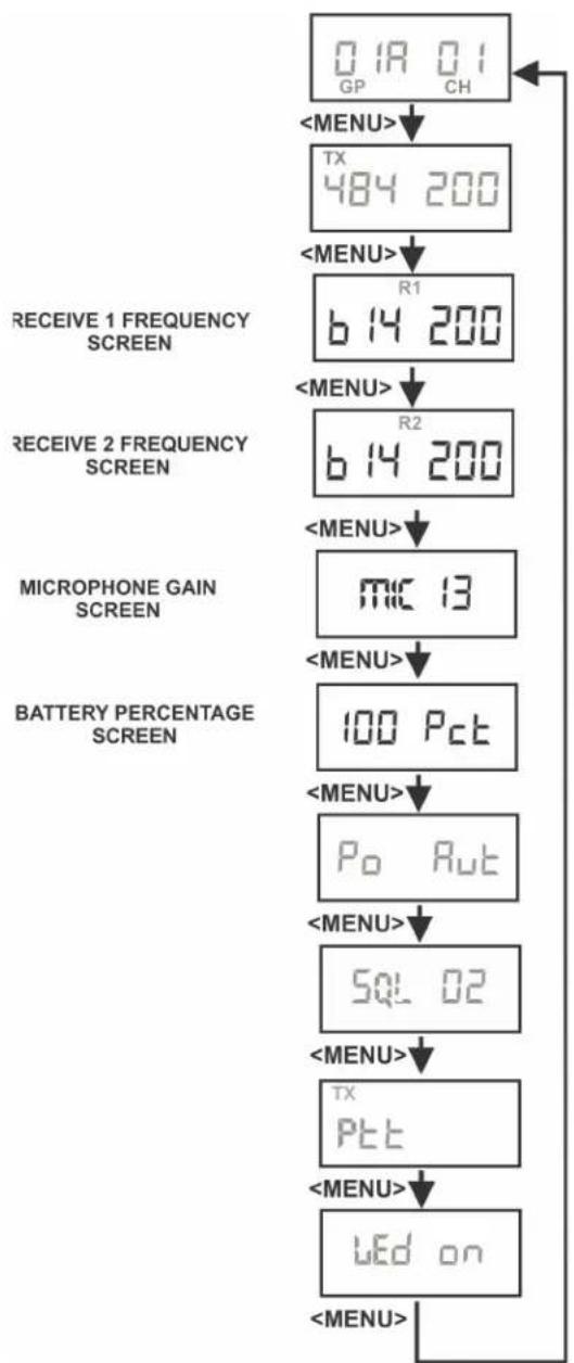
flowchart
graph TD
    A["0.1A 0.1 GP CH"] --> B["<MENU>"]
    B --> C["TX 484 200"]
    C --> D["<MENU>"]
    D --> E["R1 b 14 200"]
    E --> F["<MENU>"]
    F --> G["R2 b 14 200"]
    G --> H["<MENU>"]
    H --> I["MIC 13"]
    I --> J["<MENU>"]
    J --> K["100 Pct"]
    K --> L["<MENU>"]
    L --> M["Po Rut"]
    M --> N["<MENU>"]
    N --> O["SQL 02"]
    O --> P["<MENU>"]
    P --> Q["TX Pct"]
    Q --> R["<MENU>"]
    R --> S["LED on"]
    S --> T["<MENU>"]
FIGURE 75. Receive Frequencies
Microphone Gain/Battery Percentages Screen
Low Battery Alert Tone
The beltpack sends an audio alert tone to the headset if battery life reaches 10%. The 1 kHz tone is heard for 0.5 seconds, every 30 seconds. The tone is only heard and set at the beltpack.
To set the low battery alert tone, do the following:
- Press SET at the battery percentage screen. A screen appears displaying Lbt oFF. The low battery tone option also flashes

-
Using the UP/DOWN arrow buttons, turn the low battery tone option on or off.
-
Press SET to accept the change. The screen now displays with AL or ni flashing.

-
Using the UP/DOWN arrow buttons, select AL or ni for Alkaline/NiMH battery gauge calibration.
-
Press SET to return to the battery gauge screen.
Transmit Power
The Transmit Power screen displays the current setting of the beltpack transmitter's output power level. There are four (4) settings.
Transmit Power Settings
| Auto(Default) | The beltpack's transmitter adjusts its output level according to information sent to the beltpack from the base station. It adjusts between tow (2) levels: 5mW or 50 mW, 5 mW or 20 mW for US 3 band units. |
| 5 The beltpack transmits at 5 mW | |
| 50 or 20 | The transmitter is at 50 mW (20 mW for US 3 band units) |
| 100 or 20 | The transmitter is at 100 mW (20 mW for US 3 band units) |
When the unit is set to auto, base station information tells the beltpack the appropriate power settings to use based upon the received signal strength level at the base station. By reducing the transmit power when possible, the battery life of the beltpack can be slightly extended and intermodulation products can be reduced.
Changing the Transmit Power Setting
To change the transmit power setting, do the following:
- Push SET at the transmit power screen.
- Using the UP/DOWN arrow buttons, select the power setting.
- Push SET to place the unit at the indicated setting.
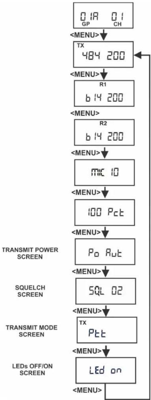
flowchart
graph TD
    A["0 1A 0 1 GP CH"] --> B["<MENU>"]
    B --> C["TX 484 200"]
    C --> D["<MENU>"]
    D --> E["R1 b 14 200"]
    E --> F["<MENU>"]
    F --> G["R2 b 14 200"]
    G --> H["<MENU>"]
    H --> I["mic 10"]
    I --> J["<MENU>"]
    J --> K["100 Pct"]
    K --> L["<MENU>"]
    L --> M["Po Rut"]
    M --> N["<MENU>"]
    N --> O["SQUELCH SCREEN"]
    O --> P["SQL 02"]
    P --> Q["<MENU>"]
    Q --> R["TRANSMIT MODE SCREEN"]
    R --> S["TX Pct"]
    S --> T["<MENU>"]
    T --> U["LEDs OFF/ON SCREEN"]
    U --> V["LED on"]
    V --> W["<MENU>"]
FIGURE 76. Transmit Power, Squelch, Push-to-Talk/Push-to-Transmit Screen (20 mW for US 3 band units)
Squelch Screen
The Squelch screen allows the user to adjust the beltpack squelch level.
To select the beltpack squelch level, do the following:
- Push SET at the squelch screen.
The squelch setting flashes.
- Using the UP/DOWN arrow buttons, select the squelch setting.
A setting of 00 holds the squelch open for testing.
WARNING: Do not set the squelch to 00 while wearing headphones with the volume turned up. White noise with no signal can be uncomfortably loud.
- Push SET to save the new squelch setting.
| Squelch Lvl | Approx. SINAD | Notes |
| 00 NA Open | ||
| 01 12 | ||
| 02 20 Default | ||
| 03 24 | ||
| 04 NA RSSI Lvl Squelch | ||
NOTE: The beltpack employs two (2) different types of squelches. A fast acting noise-type squelch and a slower data squelch. For audio to be received by the beltpack, both a good signal-to-noise audio signal (with a noise threshold set via the user squelch settings above) and a valid data stream must be detected.
Transmit Mode Screen
The Transmit Mode screen is used to select the following modes:
| Transmit Mode | Description |
| Ptt Push-to-Talk. The transmitter is always on.Pressing the TALK button un-mutes the audio.The beltpack responds to the base audio mute commands.When a user disables the beltpack Portable Station Connect button, the beltpack TALK button turns off. | |
| Pt tr Push-to- | Transmit. The transmitter is off and audio muted until the TALK button is on. The beltpack will ignore lockout or shutdown commands from the base. |
| Pt trl | Push-to-Transmit Lockout Enabled. The transmitter is off and audio muted until the TALK button is on. The beltpack will respond to lockout commands from the base, such as First-On-Latch Out and Portable Station Connect disable. |
| Pt trn | Push-to-Transmit Lockout Enabled but no busy tone. This mode is the same as Pt trL but no “busy” tone heard in beltpack if channel is occupied. |
To change the transmit mode setting, do the following:
- Push SET at the transmit mode screen. The screen flashes.
- Using the UP/DOWN arrow buttons, select the transmit mode.
- Push SET to save the mode change.
LEDs Off/On
The LED off/on screen is used to disable all LEDs. This function is useful for users who do not wish to show LEDs in the dark.
To turn LEDs on or off, do the following:
- Push SET at the LED off/on screen.
- Using the UP/DOWN arrow buttons, select the desired mode.
- Push SET to save the mode change.
Software Version/Band
The software revision and frequency band of the beltpack may be displayed from any of the main beltpack screens.
To view the software revision and frequency band, do the following:
In any of the beltpack main screens, press and hold DOWN for two (2) seconds.
- The first screen indicates the frequency band of the beltpack.
• The second screen indicates the software revision.
After displaying the information, the screen reverts back to the main screen.
The screens below indicate an E5 band beltpack with 80E052 version software.
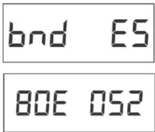
ClearScan™
ClearScan™ helps you find clear RF frequencies in your area. The beltpack's receiver scans all the factory-defined groups and any set user-defined groups. The result is a list of beltpack receive groups, clear of interference.
To enter ClearScan ^TM do the following:
- Press and hold MENU + SET for two (2) seconds to start ClearScan ^TM . The beltpack display changes to ClrScn and the GP icon flashes. After about 12 seconds, the beltpack displays the first clear group. The group number flashes.
- Using the UP/DOWN buttons, display clear groups.
- Press SET to select a group.
- Press MENU to bail out without selecting a group.
Clear groups are displayed first. They are in group order. You can scroll down through groups using the DOWN button. The left-half of the screen gives you an indication of interference levels as you scroll through the groups.
User-defined groups without a defined frequency for one of the receive channels display a u to indicate undefined.
The degree of interference found for R1 and R2 displays on the far-right two (2) positions on the screen.
| Interference Level Right Half of LCD Display | |
| None Blank | |
| Weak Single Bar | |
| Moderate Double Bar | |
| Strong Triple Bar | |
Lock Out
This function allows the user to lock the top panel and menu options. The top panel buttons still work, but the TALK button options cannot be changed. Likewise, values on the LCD screen in the beltpack can be viewed but not changed.
To enable/disable Lock Out, do the following:
- Press and hold the UP and DOWN buttons for two (2) seconds. The words Loc on appear on the screen when lock out is active.
- Press and hold the UP and DOWN buttons for two (2) seconds again to disable lock out. The words Loc off appear.
First Use Default
This function sets the beltpack to Group 1A, channel 1 and leaves any user-programmed groups in memory. It sets units to factory-defined menu settings. It also sets the TALK buttons to their default modes.
To activate the First Use Default, do the following:
Press and hold MENU while powering-up the beltpack.
Factory Reset
This function sets the beltpack to Group 1A, channel 1 and ERASES any user-defined groups in memory. It sets a unit to factory settings. It also sets the TALK buttons to their default modes.
To activate factory reset, do the following:
Press and hold MENU + SET + UP + DOWN for three (3) seconds.
RF Monitor Screen
The RF monitor screen displays beltpack RF status.
To display the beltpack RF status, do the following:
-
Press and hold MENU for two (2) seconds to display beltpack RF status.
-
If the channel button is set to 1, then signal strength displays for R1 frequency.
- If the channel button is set to 2, then signal strength displays for R2 frequency.
| TX Power Signal Strength | |
| Lo = 5mW | 0= NO |
| hi = 50mW | 1= Very Weak |
| Hi = 100mW | 2= Weak |
| 3= Moderate | |
| 4= Strong | |
| 5= Very Strong | |
- Press MENU again to exit RF Monitor Screen.
Setting Beltpack ID
Several functions require the beltpack to know which base and channel it is associated with.
- Auto Power Setting: The beltpack reduces its TX power when close to the base. Beltpack transmit power must be set to Auto.
- Portable Station Deselect: The base can disable the TALK button of a beltpack. This shuts off the mic in PTT mode and turns off the transmitter in PT TR mode.
- First-On-Latch-Out: This locks a base receive channel so only one beltpack can transmit on the frequency at a time. A beltpack user attempting to talk on top of another beltpack on the same frequency hears a double beep in their headset.
A beltpack tries to establish its ID automatically when its group/channel changes. The base must be on for this to work.
To check or set beltpack ID manually, do the following:
- Press and hold UP for two (2) seconds. The LCD displays ID Base# - Receiver#.
For example: ID 1-3 means Base 1, Receiver 3.
If the LCD displays ID--- or does not match the base and receiver, the beltpack is assigned to, Auto Power, Portable Station Deselect, and First-On-Latch Out will not work correctly.
- If the beltpack ID is correct, press MENU to exit.
- If the beltpack ID is not correct, press SET. The ID numbers flash.
- Using the UP/DOWN buttons, select a new ID.
- Press SET to apply the new ID.
Bases with transmitters enabled are always base #1. A second base using the first base transmitters instead of its own, and properly connected to the first base through CAN bus link cables becomes base #2, etc.
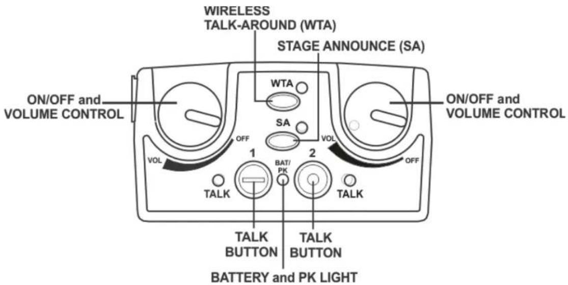
FIGURE 77. TR-82N Top Panel Controls
On/Off and Volume Control
To turn the beltpack power on, do the following:
Rotate the On/Off Volume Control knob(s) CW.
To adjust the volume to the headset, do the following:
Rotate the On/Off Volume Control knob as required for a comfortable listening volume.
Left control = channel one (1)
Right control = channel tow (2)
TALK Button
To enable the audio path from the headset microphone, do the following:
Press the TALK button.
The talk light activates when the TALK button is active. The TALK button has three (3) software selectable modes that can be seen via the LCD display of the beltpack.
To select the TALK button mode, do the following:
1. Press and hold SET while pressing the TALK button. The current mode of the TALK button displays the first time the TALK button is hit. Pressing the TALK button a second time changes the mode of the button.
2. Release SET to accept the currently displayed setting.
| Selectable Modes: TALK | 1 or 2 off TALK disabled |
| 1 or 2 on Push-to-talk | |
| 1 or 2 Lon Push-to-latch |
Battery/Peak Light
The battery/peak lights indicate battery condition and audio modulation status.
| Battery Light flashes | on power up = Battery OK | |
| Light on continuously | = Battery Low | |
| Light does of flash or come on | Battery Dead | |
| Over modulation | Light flashes on some speech | =Gain OK |
| Light flashes on all speech | -Gain too High | |
| Light never flashes on speech | -Gain too Low |
Stage Announce (SA)
To route audio from the beltpack to the stage announce connector, do the following:
Press the SA button.
The base station's SA relay closes. The beltpack sidetone is lost as an indication that stage announce is activated. The other beltpacks and wired users do not hear this beltpack's audio when SA is pressed. The button is non-latching and activates the nearby red LED when pressed.
To enable or disable Stage Announce, do the following:
- Press and hold SET while pressing the SA button. The current mode of the SA button displays.
- Still holding SET, press the SA button again to turn SA on or off.
- Release SET to accept the displayed setting.
Wireless Talk-Around (WTA)
To disconnect the beltpack audio from the wired intercom, auxiliary input/output, and the base station's local headset, do the following:
Press the WTA button.
Other beltpack users on that audio channel can hear the user as normal. The WTA button activates the nearby red LED as well as the appropriate talk LED when pressed.
To enable or disable Wireless Talk-Around options, do the following:
- Press and hold SET while pressing the WTA button.
The current WTA mode displays. Pressing WTA a second time changes modes. Options followed by an L = latch.
- Release SET to accept the displayed setting.
| tA Pb WTA | of currently selected talk button |
| tA 1L WTA | Channel 1 only-Latching |
| tA 2L WTA | Channel 2 only-Latching |
| tA 12L WTA | Channel 1 & 2-Latching |
| tA PbL WTA | of currently selected talk button-Latching |
| tA off WTA | Disabled |
| tA1 WTA Channel 1 | |
| tA2 WTA Channel 2 | |
| tA12 WTA Channel 1 & 2 | |
Groups and Channels
The first LCD screen the beltpack displays is the Group/Channel screen. This screen shows the currently selected receive group followed by the beltpack transmit channels.
To edit groups and channels, do the following:
- Push SET to edit the transmit channel. The channel number flashes.
- Using the UP/DOWN arrow buttons, select the desired transmit channel.
- Push SET to accept the channel. The receive group flashes.
- Using the UP/DOWN arrow buttons, select the desired receive group.
- Push SET to accept the receive group. The new group containing the selected channel is now set.
NOTE:
- To escape out of the editing without any changes, Press MENU.
- Factory group frequencies cannot be changed. User group frequencies (Group 19u to 30u) can be changed.
Transmit Frequency
The Transmit Frequency screen displays the beltpack transmitter frequency in MHz. The frequency is not changeable in factory-determined groups, but it is changeable in user-defined groups.
To edit the TX frequency (User Groups Only), do the following:
- Set the unit to the desired user-defined group and channels. See Groups and Channels Instructions. The menu structure in Figure 78 indicates how to get to the transmit frequency screen.
- Push SET to edit the TX frequency. The frequency flashes.
- Using the UP/DOWN arrow buttons, select the desired frequency. The frequency can be changed in 25 kHz steps.
- Push SET to place the unit on the new transmit frequency.
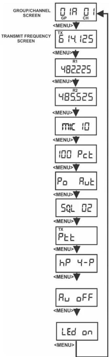
flowchart
graph TD
    A["0 1A 0 1 GP CH"] --> B["<MENU>"]
    B --> C["TX 6 14.125"]
    C --> D["<MENU>"]
    D --> E["R1 482.225"]
    E --> F["<MENU>"]
    F --> G["R2 485.525"]
    G --> H["<MENU>"]
    H --> I["MIC 10"]
    I --> J["<MENU>"]
    J --> K["100 Pct"]
    K --> L["<MENU>"]
    L --> M["Po Rut"]
    M --> N["<MENU>"]
    N --> O["SQL 02"]
    O --> P["<MENU>"]
    P --> Q["TX Pct"]
    Q --> R["<MENU>"]
    R --> S["hP 4-P"]
    S --> T["<MENU>"]
    T --> U["Ru OFF"]
    U --> V["<MENU>"]
    V --> W["LEd on"]
    W --> X["<MENU>"]
FIGURE 78. Group/Channel and Transmit Screen
Receive Frequency
The Receive Frequency screen displays the beltpack receiver frequency in MHz. The frequency cannot be changed in factory-defined groups, but can be changed in user-defined groups.
To edit the RX frequency (User Groups Only), do the following:
- Set the unit to the desired user-defined group and channels. See Groups and Channels Instructions. The menu structure in Figure 79 indicates how to get to the receive frequency screen.
- Push SET to edit the RX frequency. The frequency flashes.
- Using the UP/DOWN arrow buttons, select the desired frequency.
The frequency can be changed in 25 kHz steps.
- Push SET to place the unit on the new receive frequency.
Microphone Gain
The Microphone Gain screen displays the beltpack microphone gain setting. There are 16 possible settings. The number zero (0) indicates minimum microphone gain, the number 15 is maximum. Each step is about three (3) dB.
To adjust the microphone gain, do the following:
- Push SET at the microphone gain screen. The number flashes.
- Using the UP/DOWN arrow buttons, to select the desired gain.
- Push SET to place the unit at the indicated microphone gain.
Battery Display
The Battery Display screen indicates the current percentage of battery remaining.
Battery Percentages
100 Pct. = Fresh Battery
75 Pct. = 75% Life Left
50 Pct. = 50% Life Left
25 Pct. = 25% Life Left
10 Pct. = 10% Life Left. Low Battery Light.
0 Pct. = Battery Dead. Unit will lose communication at any time.

flowchart
graph TD
    A["01A 01 GP CH"] --> B["<MENU>"]
    B --> C["TX 484 200"]
    C --> D["<MENU>"]
    D --> E["R1 614 200"]
    E --> F["<MENU>"]
    F --> G["R2 614 200"]
    G --> H["<MENU>"]
    H --> I["MIC 13"]
    I --> J["<MENU>"]
    J --> K["100 Pct"]
    K --> L["<MENU>"]
    L --> M["Po Rut"]
    M --> N["<MENU>"]
    N --> O["SQL 02"]
    O --> P["<MENU>"]
    P --> Q["TX Pct"]
    Q --> R["<MENU>"]
    R --> S["LED on"]
    S --> T["<MENU>"]
FIGURE 79.
Receive frequencies/Microphone Gain Battery Percentage Screen
Low Battery Alert Tone
The beltpack sends an audio alert tone to the headset if battery life reaches 10%. The 1 kHz tone is heard for 0.5 seconds, every 30 seconds. The tone is only heard and set at the beltpack.
To set the low battery alert tone, do the following:
- Press SET at the battery percentage screen. A screen appears displaying Lbt oFF. The low battery tone option also flashes
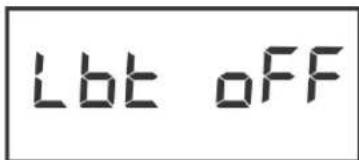
-
Using the UP/DOWN arrow buttons, turn the low battery tone option on or off.
-
Press SET to accept the change. The screen now displays with AL or ni flashing.
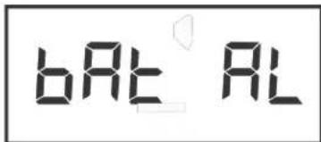
-
Using the UP/DOWN arrow buttons, select AL or ni for Alkaline/NiMH battery gauge calibration.
-
Press SET to return to the battery gauge screen.
Transmit Power
The Transmit Power screen displays the current setting of the beltpack transmitter's output power level. There are four (4) settings.
Transmit Power Settings
| Auto(Default) | The beltpack's transmitter adjusts its output level according to information sent to the beltpack from the base station. It adjusts between tow (2) levels: 5mW or 50 mW. |
| 5 The beltpack transmits at 5 mW | |
| 50 The transmitter is at 50 mW | |
| 100 The transmitter is at 100 mW | |
When the unit is set to auto, base station information tells the beltpack the appropriate power settings to use based upon the received signal strength level at the base station. By reducing the transmit power when possible, the battery life of the beltpack can be slightly extended and intermodulation products can be reduced.
To change the transmit power setting, do the following:
- Push SET at the transmit power screen.
- Using the UP/DOWN arrow buttons, select the power setting.
- Push SET to place the unit at the indicated setting.

flowchart
graph TD
    A["GROUP/CHANNEL SCREEN"] --> B["0 1A 0 1 GP CH"]
    B --> C["<MENU>"]
    C --> D["TX 6 14.125"]
    D --> E["<MENU>"]
    E --> F["R1 482.225"]
    F --> G["<MENU>"]
    G --> H["R2 485.525"]
    H --> I["<MENU>"]
    I --> J["MIC 10"]
    J --> K["<MENU>"]
    K --> L["100 Pct"]
    L --> M["<MENU>"]
    M --> N["Po Rut"]
    N --> O["<MENU>"]
    O --> P["SQL 02"]
    P --> Q["<MENU>"]
    Q --> R["TX Ptt"]
    R --> S["<MENU>"]
    S --> T["hP 4-P"]
    T --> U["<MENU>"]
    U --> V["Au OFF"]
    V --> W["<MENU>"]
    W --> X["LEd on"]
    X --> Y["<MENU>"]
FIGURE 80.
Transmit Power/Squelch Screen
Squelch Screen
The Squelch screen allows the user to adjust the beltpack squelch level.
To adjust the squelch level, do the following:
- Push SET at the squelch screen.
The squelch setting flashes.
- Using the UP/DOWN arrow buttons, select the squelch setting.
A setting of 00 holds the squelch open for testing.
WARNING: Do not set the squelch to 00 while wearing headphones with the volume turned up. White noise with no signal can be uncomfortably loud.
- Push SET to save the new squelch setting.
| Squelch Lvl | Approx. SINAD | Notes |
| 00 NA Open | ||
| 01 12 | ||
| 02 20 Default | ||
| 03 24 | ||
| 04 NA RSSI Lvl Squelch | ||
NOTE: The beltpack employs two (2) different types of squelches. A fast acting noise-type squelch and a slower data squelch. For audio to be received by the beltpack, both a good signal-to-noise audio signal (with a noise threshold set via the user squelch settings above) and a valid data stream must be detected.
Headphone Options:
- If the TR-82N has a 4-pin headset connector, the headphone should be set to hP 4-P (4-pin).
- When supplied with a 5-pin (stereo) headset connector, the settings hP Add should be used for Mono or hP SEP for channel 1 in left earpiece and channel 2 in right earpiece.
- A 5-pin single-sided headset should be set to hP 4-P.
Auxiliary Input:
The TR-82N has a 3.5 mm mono auxiliary input jack. Audio from this jack is heard only in the beltpack headset.
To set the Auxiliary mode, do the following:
- Press SET.
- Using the UP/DOWN arrow buttons, select the AUX mode setting.
| Setting Auxiliary Input Function | |
| Off Aux | input disabled |
| 1 | Aux heard with Ch 1 |
| 2 | Aux heard with Ch 2 |
| 12 | Aux heard with Ch 1 & 2 |
- Press SET to accept the screen setting. If Aux is not Off, the next screen displays Au NN where NN is a two (2) digit number between 0 and 15. This is the volume level setting for the aux input.
- Press SET. The two (2) digits will flash.
- Using the UP/DOWN arrow buttons, select the AUX volume.
- Press SET to accept the gain setting.
Transmit Mode Screen
The Transmit Mode screen is used to select the following modes:
| Transmit Mode | Description |
| Ptt | Push-to-Talk. The transmitter is always on. Pressing the TALK button un-mutes the audio. The beltpack responds to the base audio mute commands.When a user disables the beltpack Portable Station Connect button, the beltpack TALK button turns off. |
| Pt tr | Push-to-Transmit. The transmitter is off and audio muted until the TALK button is on. The beltpack will ignore lockout or shutdown commands from the base. |
| Pt trl | Push-to-Transmit Lockout Enabled. The transmitter is off and audio muted until the TALK button is on. The beltpack will respond to lockout commands from the base, such as First-On-Latch Out and Portable Station Connect disable. |
| Pt trn | Push-to-Transmit Lockout Enabled but no busy tone. This mode is the same as Pt trL but no “busy” tone heard in beltpack if channel is occupied. |
To change the transmit mode setting, do the following:
- Push SET at the transmit mode screen. The screen flashes.
- Using the UP/DOWN arrow buttons, select the transmit mode.
- Push SET to save the mode change.
LEDs Off/On
The LED Off/On screen is used to disable all LEDs. This function is useful for users who do not wish to show LEDs in the dark.
To turn LEDs on or off, do the following:
-
Push SET at the LED off/on screen.
-
Using the UP/DOWN arrow buttons, select the desired mode.
Software Version/Band
The Software Revision and Frequency Band of the beltpack may be displayed from any of the main beltpack screens.
To view the software revision and frequency band, do the following:
In any of the beltpack main screens, press and hold DOWN for two (2) seconds.
- The first screen indicates the frequency band of the beltpack.
• The second screen indicates the software revision.
After displaying the information, the screen reverts back to the main screen.
The screens below indicate an E5 band beltpack with 80E052 version software.

ClearScan™
ClearScan™ helps you find clear RF frequencies in your area. The beltpack's receiver scans all the factory-defined groups and any set user-defined groups. The result is a list of beltpack receive groups, clear of interference.
To enter ClearScan ^TM , do the following:
- Press and hold MENU + SET for two (2) seconds to start ClearScan ^TM . The beltpack display changes to ClrScn and the GP icon flashes. After about 12 seconds, the beltpack displays the first clear group. The group number flashes.
- Using the UP/DOWN arrow buttons, display the clear groups.
- Press SET to select a group.
- Press MENU to bail out without selecting a group.
Clear groups are displayed first. They are in group order. You can scroll down through groups using the DOWN button. The left-half of the screen gives you an indication of interference levels as you scroll through the groups.
User-defined groups without a defined frequency for one of the receive channels display a u to indicate undefined.
The degree of interference found for R1 and R2 displays on the far-right two (2) positions on the screen.
| Interference Level Right Half of LCD Display | |
| None Blank | |
| Weak Single Bar | |
| Moderate Double Bar | |
| Strong Triple Bar | |
Lock Out
Lock Out allows the user to lock the top panel and menu options. The top panel buttons still work, but the TALK button options cannot be changed. Likewise, values on the LCD screen in the beltpack can be viewed but not changed.
To enable/disable Lock Out, do the following:
- Press and hold the UP and DOWN buttons for two (2) seconds.
The words Loc on appear on the screen when lock out is active. - Press and hold the UP and DOWN buttons for two (2) seconds again to disable lock out.
The words Loc off appear.
First Use Default
First Use Default sets the beltpack to Group 1A, channel 1 and leaves any user-programmed groups in memory. It sets units to factory-defined menu settings. It also sets the TALK buttons to their default modes.
To activate the 1st Use Default, do the following:
Press and hold MENU while powering-up the beltpack.
Factory Reset
Factory Reset sets the beltpack to Group 1A, channel 1 and ERASES any user-defined groups in memory. It sets a unit to factory settings. It also sets the TALK buttons to their default modes.
To activate factory reset, do the following:
Press and hold MENU + SET + UP + DOWN for two (2) seconds.
RF Monitor Screen
The RF Monitor Screen displays beltpack RF status.
To display the beltpack RF status, do the following:
-
Press and hold MENU for two (2) seconds to display beltpack RF status.
-
If the channel button is set to 1, then signal strength displays for R1 frequency.
- If the channel button is set to 2, then signal strength displays for R2 frequency.
| TX Power Signal Strength |
| Lo = 5mW 0 = NO |
| hi = 50mW 1 = Very Weak |
| Hi = 100 mW 2 = Weak |
| 3= Moderate |
| 4= Strong |
| 5= Very Strong |
- Press MENU again to exit RF Monitor Screen.
Setting Beltpack ID
Several functions require the beltpack to know which base and channel it is associated with.
- Auto Power Setting: The beltpack reduces its TX power when close to the base. Beltpack transmit power must be set to Auto.
- Portable Station Deselect: The base can disable the TALK button of a beltpack. This shuts off the mic in PTT mode and turns off the transmitter in PT TR mode.
- First-On-Latch-Out: This locks a base receive channel so only one beltpack can transmit on the frequency at a time. A beltpack user attempting to talk on top of another beltpack on the same frequency hears a double beep in their headset.
A beltpack tries to establish its ID automatically when its group/channel changes. The base must be on for this to work.
To check or set beltpack ID manually, do the following:
- Press and hold UP for two (2) seconds. The LCD displays ID Base# - Receiver#.
For example: ID 1-3 means Base 1, Receiver 3.
If the LCD displays ID--- or does not match the base and receiver, the beltpack is assigned to, Auto Power, Portable Station Deselect, and First-On-Latch Out will not work correctly.
- If the beltpack ID is correct, press MENU to exit.
- If the beltpack ID is not correct, press SET. The ID numbers flash.
- Using the UP/DOWN buttons, select a new ID.
- Press SET to apply the new ID.
Bases with transmitters enabled are always base #1. A second base using the first base transmitters instead of its own, and properly connected to the first base through CAN bus link cables becomes base #2, etc.
APPENDIX A
Additional Resources
BTR-80N Menu Structure
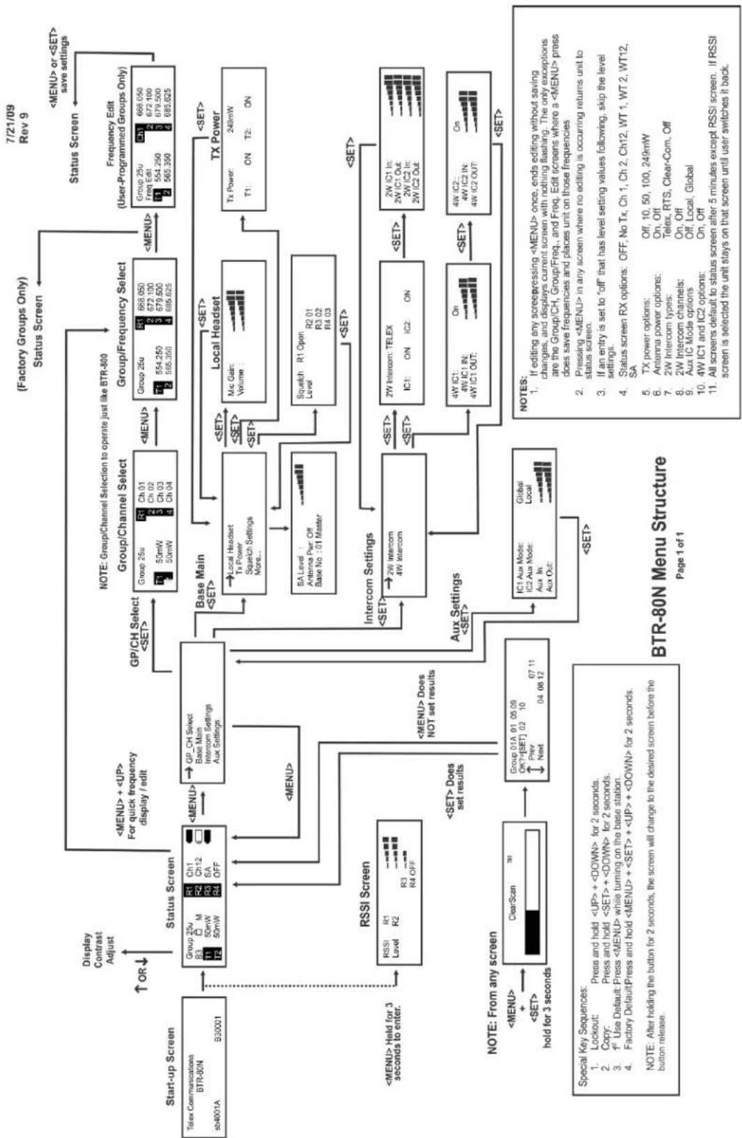
flowchart
graph TD
A["Start-up Screen"] --> B["Telex Communications BTR-80N sb4001A"]
B --> C["Group 25u R3 M 50mW R2 SA 50mW R4 OFF"]
C --> D["Status Screen"]
D --> E["GP/CH Select <SET>"]
E --> F["Group/Channel Select"]
F --> G["Group 25u R1 Ch 01 Ch 02 Ch 03 Ch 04"]
G --> H["Group/Frequency Select"]
H --> I["Group 25u R1 668.050 672.100 679.500 685.625"]
I --> J["Frequency Edit (User-Programmed Groups Only)"]
J --> K["Group 25u CH1 668.050 672.100 679.500 685.625"]
K --> L["7/21/09 Rev 9"]
L --> M["Display Contrast Adjust ↑ OR ↓"]
M --> N["<MENU> + <UP> For quick frequency display / edit"]
N --> O["<MENU> Does NOT set results"]
O --> P["Base Main <SET>"]
P --> Q["Local Headset Tx Power Squelch Settings More..."]
Q --> R["SA Level: Antenna Pur: Off Base No :01 Master"]
R --> S["Intercom Settings"]
S --> T["2W Intercom TELEX IC1 ON IC2 ON"]
T --> U["4W IC1: 4W IC1 IN: 4W IC1 OUT: On"]
U --> V["4W IC2: 4W IC2 IN: 4W IC2 OUT: On"]
V --> W["Intercom Settings"]
W --> X["Aux Settings <SET>"]
X --> Y["IC1 Aux Mode: Global Local Aux In: Aux Out"]
Y --> Z["ClearScan TM1 hold for 3 seconds"]
Z --> AA["RSI Screen"]
AA --> AB["RSSI Level R1 R2 R3 R4 OFF"]
AB --> AC["<MENU> Held for 3 seconds to enter"]
AC --> AD["<MENU> Does not set results"]
AD --> AE["<SET> Does set results"]
AE --> AF["BTR-80N Menu Structure Page 1 of 1"]
AF --> AG["NOTES: If editing any screepressing <MENU> once, ends editing without saving changes, and displays current screen with nothing flashing. The only exceptions are the Group/CH, Group/Freq., and Freq. Edit screens where a <MENU> press does save frequencies and places unit on those frequencies. Pressing <MENU> in any screen where no editing is occurring returns unit to status screen. If an entry is set to "off" that has level setting values following, skip the level settings. Status screen RX options: OFF, No Tx, Ch 1, Ch 2, Ch12, WT 1, WT 2, WT12, SA TX power options: Off, 10, 50, 100, 249mW Antenna power options: On, Off 2W Intercom types: Telex, RTS, Clear-Com, Off 2W Intercom channels: On, Off 9 Aux IC Mode options: Off, Local, Global 4W IC1 and IC2 options: On, Off All screens default to status screen after 5 minutes except RSSI screen. If RSSI screen is selected the unit stays on that screen until user switches it back."]
TR-80N Beltpack Screen
Flowchart
5/20/2009 Rev3
TR-80N Beltpack Screen Flowchart

flowchart
graph LR
    A["Group / Channel"] --> B["19u 01 CP CH"]
    B --> C["19u 01 CP CH"]
    C --> D["9u 01 CP CH"]
    D --> E["9u 01 CP CH"]
    E --> F["19u 01 CP CH"]
    F --> G["19u 01 CP CH"]
    G --> H["19u 01 CP CH"]
    H --> I["19u 01 CP CH"]
    I --> J["19u 01 CP CH"]
    J --> K["19u 01 CP CH"]
    K --> L["19u 01 CP CH"]
    L --> M["19u 01 CP CH"]
    M --> N["19u 01 CP CH"]
    N --> O["19u 01 CP CH"]
    O --> P["19u 01 CP CH"]
    P --> Q["19u 01 CP CH"]
    Q --> R["19u 01 CP CH"]
    R --> S["19u 01 CP CH"]
    S --> T["19u 01 CP CH"]
    T --> U["19u 01 CP CH"]
    U --> V["19u 01 CP CH"]
    V --> W["19u 01 CP CH"]
    W --> X["19u 01 CP CH"]
    X --> Y["19u 01 CP CH"]
    Y --> Z["19u 01 CP CH"]
    Z --> AA["19u 01 CP CH"]
    AA --> AB["19u 01 CP CH"]
    AB --> AC["19u 01 CP CH"]
    AC --> AD["19u 01 CP CH"]
    AD --> AE["19u 01 CP CH"]
    AE --> AF["19u 01 CP CH"]
    AF --> AG["19u 01 CP CH"]
    AG --> AH["19u 01 CP CH"]
    AH --> AI["19u 01 CP CH"]
    AI --> AJ["19u 01 CP CH"]
    AJ --> AK["19u 01 CP CH"]
    AK --> AL["19u 01 CP CH"]
    AL --> AM["19u 01 CP CH"]
    AM --> AN["19u 01 CP CH"]
    AN --> AO["19u 01 CP CH"]
    AO --> AP["19u 01 CP CH"]
    AP --> AQ["19u 01 CP CH"]
    AQ --> AR["19u 01 CP CH"]
    AR --> AS["19u 01 CP CH"]
    AS --> AT["19u 01 CP CH"]
    AT --> AU["19u 01 CP CH"]
    AU --> AV["19u 01 CP CH"]
    AV --> AW["19u 01 CP CH"]
    AW --> AX["19u 01 CP CH"]
    AX --> AY["19u 01 CP CH"]
    AY --> AZ["19u 01 CP CH"]
    AZ --> BA["19u 01 CP CH"]
    BA --> BB["19u 01 CP CH"]
    BB --> BC["19u 01 CP CH"]
    BC --> BD["19u 01 CP CH"]
    BD --> BE["19u 01 CP CH"]
    BE --> BF["19u 01 CP CH"]
    BF --> BG["19u 01 CP CH"]
    BG --> BH["19u 01 CP CH"]
    BH --> BI["19u 01 CP CH"]
    BI --> BJ["19u 01 CP CH"]
    BJ --> BK["19u 01 CP CH"]
    BK --> BL["19u 01 CP CH"]
    BL --> BM["19u 01 CP CH"]
    BM --> BN["19u 01 CP CH"]
    BN --> BO["19u 01 CP CH"]
    BO --> BP["19u 01 CP CH"]
    BP --> BQ["19u 01 CP CH"]
    BQ --> BR["19u 01 CP CH"]
    BR --> BS["19u 01 CP CH"]
    BS --> BT["19u 01 CP CH"]
    BT --> BU["19u 01 CP CH"]
    BU --> BV["19u 01 CP CH"]
    BV --> BW["19u 01 CP CH"]
    BW --> BX["19u 01 CP CH"]
    BX --> BY["19u 01 CP CH"]
    BY --> BZ["19u 01 CP CH"]
    BZ --> CA["19u 01 CP CH"]
    CA --> CB["19u 01 CP CH"]
    CB --> CC["19u 01 CP CH"]
    CC --> CD["19u 01 CP CH"]
    CD --> CE["19u 01 CP CH"]
    CE --> CF["19u 01 CP CH"]
    CF --> CG["19u 01 CP CH"]
    CG --> DH["19u 01 CP CH"]
    DH --> DI["19u 01 CP CH"]
    DI --> DJ["19u 01 CP CH"]
    DJ --> DK["19u 01 CP CH"]
    DK --> DL["19u 01 CP CH"]
    DL --> DM["19u 01 CP CH"]
    DM --> DN["19u 01 CP CH"]
    DN --> DO
    DO --> DO
| Special Key Functions | |||||||||
| Tx Power and Receiver RSSI | Beltpack Identification | Software Band Software Version | ClearScan | Talk Button Options | Stage Announce (SA) | Wireless Talk Around (WTA) | Lockout | 1stUse Default | Factory Reset Default |
| Hold [MENU] for 2 seconds | Hold | ↑| for 2 seconds | Hold | ↓ for 2 seconds | Hold [MENU] + [SET] for 1 sec. | Hold [SET] and press [TALK] | Hold [SET] and press [SA] | Hold [SET] and press [WTA] | Hold [↑] - [↓] for 2 seconds | Hold [MENU] as powering-up unit | Hold [MENU] + [SET] + [↑] + [↓] for 2 seconds |
| Press [MENU] to exit to normal menus | [SET] | Displayed for 1 second | CLr Scn | [ TALK ] | [SA] | [ WTA ] | Loc on | 01A 01- | FAc rES |
| Function: Display current TX power of unit: Hi = 100mW bi = 50mW Lo = 5mW -- = Off | [SET] | Displayed for 1 second or when [↓] released | After 10 seconds best group selected [SET] ↓ | [ TALK ] | [SA] | [ WTA ] | Hold [↑] + [↓] again for 1 second | Sets unit to Group 01A, Channel 01, with 01 flashing. User must set channel number. | Sets unit to Group 01A, Channel 01, with 01 flashing. User must set channel number. |
| Display receiver strength; 0 - 5; 0 = Clear 5 = Strong Signal | Press [MENU] to exit to normal menus | Back to normal menu | 01A 01- | Function: Talk button operation, on = Talk Latch on off = Monetary | Function: Menu items can be viewed but not changed when activated. | Sets Unit to defaults | Sets Unit to defaults | ||
| Function: View ID assigned to belpack by base station | All user defined gourps are Retained | All user defined gourps are Erased | |||||||
| May also be used to change belpack ID. | |||||||||
TR-82N Beltpack Screen Flowchart
5/20/2009
Rev3
TR-82N Beltpack Screen Flowchart
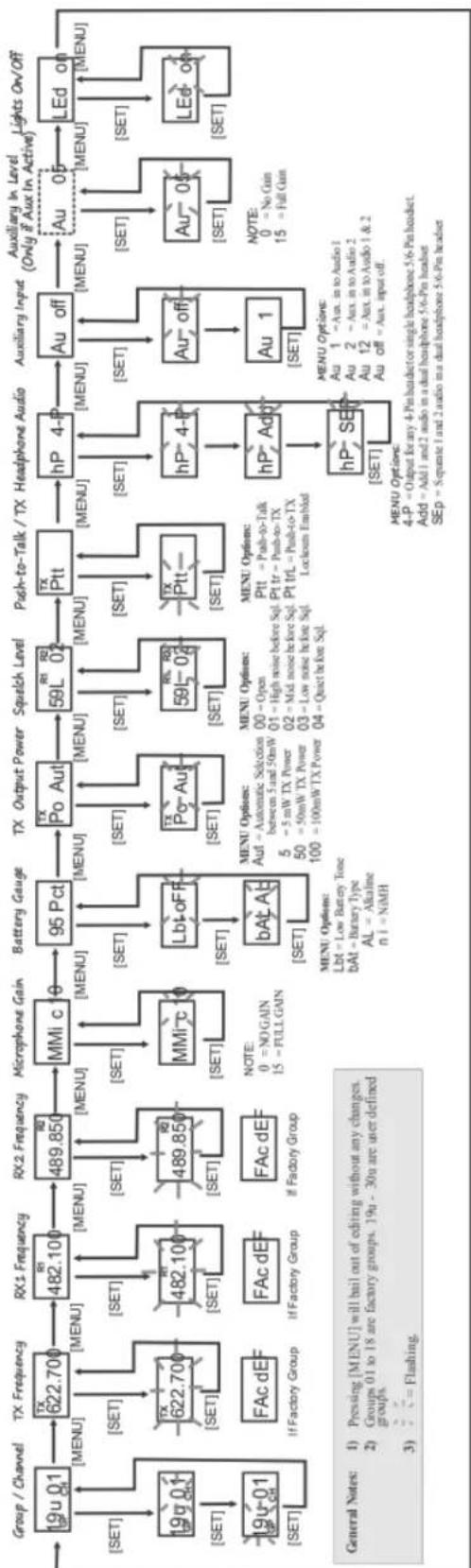
flowchart
graph LR
    A["Group / Channel"] --> B["19u 01"]
    B --> C["FX Frequency"]
    C --> D["RX1 Frequency"]
    D --> E["RX2 Frequency"]
    E --> F["MMI c 10"]
    F --> G["Battery Gauge"]
    G --> H["95 Pct"]
    H --> I["TX Output Power"]
    I --> J["Squelch Level"]
    J --> K["TX Ptt"]
    K --> L["hP 4-P"]
    L --> M["Auxiliary Input"]
    M --> N["Auxiliary In Level (Only if Aux In Active)"]
    N --> O["LEd on"]

    subgraph General Notes
        P["1) Pressing [MENU"] will bail out of editing without any changes.
        2) Groups 01 to 18 are factory groups. 19u - 30u are user defined groups.
        3) = Flashing.
    end

    A --> Q["19u 01"]
    Q --> R["FX Frequency"]
    R --> S["RX1 Frequency"]
    S --> T["RX2 Frequency"]
    T --> U["MMI c 10"]
    U --> V["Battery Gauge"]
    V --> W["95 Pct"]
    W --> X["TX Output Power"]
    X --> Y["Squelch Level"]
    Y --> Z["TX Ptt"]
    Z --> AA["hP 4-P"]
    AA --> AB["Auxiliary Input"]
    AB --> AC["Auxiliary In Level (Only if Aux In Active)"]
    AC --> AD["LEd on"]

    subgraph General Notes
        AE["NOTE: 0 = NO GAIN<br>        15 = FULL GAIN"]
        AF["MENU Options: Lbt = Low Battery Tone<br>bAt = Binary Type<br>AL = Alkalme<br>n 1 = NiMH"]
        AG["MENU Options: Lbt = Low Battery Tone<br>bAt = Binary Type<br>AL = Alkalme<br>n 1 = NiMH"]
        AH["MENU Options: 4-P = Output for any 4-Pin headset or single headphone 5/6-Pin headset.<br>Add = Add 1 and 2 audio in a dual headphone 5/6-Pin headset<br>Sep = Separate 1 and 2 audio in a dual headphone 5/6-Pin headset"]
        AI["NOTE: 0 = No Gain<br>        15 = Full Gain"]
        AJ["Au 1 = Aux. in to Audio 1<br>Au 2 = Aux. in to Audio 2<br>Au 12 = Aux. in to Audio 1 & 2<br>Au off = Aux. input off"]
        AK["LEd on"]
    end
| Special Key Functions | ||||||||
| Tx Power and Rx2/ Rx2. RSSI | Beltpack Identification | Software Band Software Version | ClearScan | Talk Button Options | Stage Announce (SA) | Wireless Talk Around (WTA) | Lockout | Use Default |
| Hold [MENU] for 2 seconds | Hold [↑] for 2 seconds | Hold [↓] for 2 seconds | Hold [MENU] + [SET] for 2 sec. | Hold [SET] and press [TALK] | Hold [SET] and press [SA] | Hold [SET] and press [WTA] | Hold [↑] + ↓ for 2 seconds | Hold [MENU] as powering-up unit |
| Press [MENU] to exit to normal menus | [SET] | [SET] | [SET] | [SET] | [SET] | [SET] | [SET] | [SET] + [↑] + [↓] for 1 second |
| Function: Display current TX power of unit | [SET] | [SET] | [SET] | [SET] | [SET] | [SET] | [SET] | [SET] |
| H = 100mW N = 50mW Lo = 50w - - = Off | Press [MENU] to exit to normal menus | Back to normal menu | After 8 seconds best group selected [SET] | After 8 seconds best group selected [SET] | After 8 seconds best group selected [SET] | After 8 seconds best group selected [SET] | After 8 seconds best group selected [SET] | After 8 seconds best group selected [SET] |
| Displayover 1 and 2 signal strength: 0 = 5 0 = Clear 5 = Strong Signal | Function: View ID assigned to bitpack by base station. May also be used to change bitpack ID. | Group / Channel Screen | Function: Talk button operation Lon = Talk Latch on off = Talk off on = Nometary or | Function: Menu items can be viewed but not changed when activated. | Set unit to defaults All user defined groups retained. | Set unit to defaults All user defined groups erased | ||
Frequency Bands
The BTR-80N system operates over the following frequency ranges:
North America
- Base TX: 482-608 MHz
- Base RX: 572-608 MHz, US 3 Band: 653-663 MHz
Europe
- Base TX: 482-608 MHz
- Base RX: 572-608, 614-722 MHz
The bands, US TV channels, and frequencies are shown in Figure 81. Most bands are 18 MHz wide.
Bands F to C are always base transmit bands (beltpack receive bands). Bands 1-6 are always base receive bands (beltpack transmit bands). Bands D and E can be both a base transmit or receive band, depending on the unit ordered. Thus an A2 base station is comprised of an A band transmitter and a two (2) band receiver.
Band Pairing for Systems
All band pairs cannot be made into a system. Table 3 show the available band pairings.
| Base TX Bands Base RX Bands | |
| F | D, E, 1, 2, 3, 4, 5, 6 |
| H | E, 1, 2, 3, 4, 5, 6 |
| A | 1, 2, 3, 4, 5, 6 |
| B | 2, 3, 4, 5, 6 |
| C | 3, 4, 5, 6 |
| D | 4, 5, 6 |
| E | 5, 6 |
TABLE 3. Available band pairings
In Table 3, it can be seen that a C base station transmit band can be paired with 3, 4, 5, or 6 receive bands. However, a C2 unit cannot be made. This is because a certain amount of frequency separation between transmit nad receive bands is required for good transmit and receive operation. If they are too close the RF performance of the system is reduced.
FIGURE 81. Band Names Frequencies and US TV Channels
| Band US TV | Freq. | Start | Freq. End | US TV |
| F | 16 482 | 488 16 | ||
| 17 488 | 494 17 | |||
| 18 494 | 500 18 | |||
| H | 19 500 | 506 19 | ||
| 20 506 | 512 20 | |||
| 21 512 | 518 21 | |||
| A | 22 518 | 524 22 | ||
| 23 524 | 530 23 | |||
| 24 560 | 536 24 | |||
| B | 25 536 | 542 25 | ||
| 26 542 | 548 26 | |||
| 27 548 | 554 27 | |||
| C | 28 554 | 560 28 | ||
| 29 560 | 566 29 | |||
| 30 566 | 572 30 | |||
| D | 31 572 | 578 31 | ||
| 32 578 | 584 32 | |||
| 33 584 | 590 33 | |||
| E | 34 590 | 596 34 | ||
| 35 596 | 602 35 | |||
| 36 602 | 608 36 | |||
| 37 608 | 614 37 | |||
| 1 EURO ONLY | 38 614 | 620 38 | ||
| 39 620 | 626 39 | |||
| 40 626 | 632 40 | |||
| 2 EURO ONLY | 41 632 | 638 41 | ||
| 42 638 | 644 42 | |||
| 43 644 | 650 43 | |||
| 3 EURO ONLY & US (10MHz) | 44 650 | 656 44 | ||
| 45 656 | 662 45 | |||
| 46 662 | 668 46 | |||
| 4 EURO ONLY | 41 668 | 674 47 | ||
| 48 674 | 680 48 | |||
| 49 680 | 686 49 | |||
| 5 EURO ONLY | 50 686 | 692 50 | ||
| 51 692 | 698 51 | |||
| 52 698 | 704 52 | |||
| 6 EURO ONLY | 53 704 | 710 53 | ||
| 54 710 | 716 54 | |||
| 55 716 | 722 55 |
Frequency Plan
There are 48 groups in a BTR-80N system. The 48 groups are divided up into 36 factory-defined groups and 12 user-defined groups. A group referenced to a base station is comprised of two TX channels and up to 12 RX channels.
User-defined groups are blank initially and allow the user to enter their own frequencies.
Factory-defined groups are composed of frequencies that cannot be modified by the user. The 36 groups are composed of the following:
Nine (9) Triplet Groups
- Groups 1a to 9c
Nine (9) Single Groups
- Groups 10-18
The factory groups are organized in different ways to provide flexibility to the user on selecting frequencies. A groups is composed of intermodulation free frequencies. The triplet groups may be used together for up to three (3) systems that are intermodulation coordinated. For example, three intermodulation coordinated systems may be set up by using the following groups and channels:
• System A = Group 1a, channels: 1, 2, 3, 4
• System B = Groups 1b, channels: 5, 6, 7, 8
• System C = Group 1c, channels: 9, 10, 11, 12
A group also contains frequencies within different combinations of the TV channels. The user can select a group clear of broadcast Tv channels in the area by selecting a group(s) not using those channels.
Figure 82 indicates how the factory-defined groups used the three (3) TV channels for TX and three (3) TV channels for receive. These plans are based upon US broadcast TV channels. A darkened TV channel indicates the group has frequencies in the channel. The white TV channel indicates the group has no frequencies in the channel. For example, Group 1A uses at least one (1) frequency from each of the three (3) TV channels for RX and only the 1st TV channel for TX. However, group 18 uses only the 3rd TV channel for TX and RX.
Three band base stations and beltpacks used in the US have a reduced channel map offering due to regulatory changes that reduce the size of the three bands.
For more information, see “Three (3) Band Base Stations” on page 86.
| Base TX Freq. | Base RX Freq. | ||||||
| TV1 | TV2 | TV3 | TV4 | TV5 | TV6 | ||
| 1a | |||||||
| 1b | |||||||
| 1c | |||||||
| 2a | |||||||
| 2b | |||||||
| 2c | |||||||
| 3a | |||||||
| 3b | |||||||
| 3c | |||||||
| 4a | |||||||
| 4b | |||||||
| 4c | |||||||
| 5a | |||||||
| 5b | |||||||
| 5c | |||||||
| 6a | |||||||
| 6b | |||||||
| 6c | |||||||
| 7a | |||||||
| 7b | |||||||
| 7c | |||||||
| 8a | |||||||
| 8b | |||||||
| 8c | |||||||
| 9a | |||||||
| 9b | |||||||
| 9c | |||||||
| 10 | |||||||
| 11 | |||||||
| 12 | |||||||
| 13 | |||||||
| 14 | |||||||
| 15 | |||||||
| 16 | |||||||
| 17 | |||||||
| 18 | |||||||
FIGURE 82.
Groups and Tv Channels Used
Dark = TV used
Light = TV not used
Troubleshooting
| PROBLEM SOLUTION | |
| DISTORTION - System's audio quality seems distorted at medium to high input levels | Reduce microphone gain by adjusting microphone gain control in software. |
| HISS - System seems to produce a hiss which is undesirable. | Check the gain setting on all beltpacks and the base. They may be too low or too high. Check to make sure you are still well within range of the base station. |
| LOW OUTPUT - System produces a low output level. | Check the gain setting on both the beltpacks and the base. They may be too low. |
| FEEDBACK - Moving around are of use produces squcal or howl in various locations using the ext. speakers. | Reduce the gain settings on both the beltpacks and the base. They may be too high. If in 2-wire mode, the intercom channel you are on may be unloaded. |
| DROPUOUTS - When moving around the area of use there seem to be locations where the signal swooshes or completely disappears. | Make sure both antennas on the base and beltpack are connected and follow the location suggestions. Change the location of the base unit and antennas or avoid the bad areas with the remote beltpacks. |
| INTERFERENCE - System picks up signals other than wireless intercoms. | Make sure the Telex beltpack(s) are on. If there are any unused receivers at the base, turn the audio off from those receivers by deselecting the appropriate Portable Station Connect button.If problems persist with the beltpack on, you will probably need to change the group. Make sure the base and beltpack match after any Group/Channel change. |
| NO AUDIO - from base of beltpack headsets. | Check transmitter setting on base and beltpack. Check talk LED to ensure it is on. Make sure beltpack batteries are OK. |
| BASE and BELTPACK'S Frequencies Don't Match - In the display frequencies screen of the base and the menu of the beltpack the frequencies don't match. | Ensure the units are on the correct Group and Channels. If three (3) band base and beltpack units and in the US, make sure you have switched the base station to the US channel map. See “Three (3) Band Base Stations” on page 86. |
IMPORTANT: Reread the sections of this manual to make sure you completed system set-up properly. If you are unable to solve the problem, contact the dealer from whom you purchased the system for assistance
Battery Information
Improper battery selection, use, installation, and care are the cause of numerous wireless systems failures.
Alkaline Batteries: Alkaline batteries such as Eveready's ENERGIZER and ENERGIZER INDUSTRIAL provide the most reliable operation in wireless transceivers.
The use of low cost carbon-zinc batteries is NOT recommended.
Nickel-Metal Hydride Batteries: These batteries can save you money in the long run, as they can be recharged. Typical battery life is a little less than the length of time alkaline batteries last.
Battery Warnings
- Do not place alkaline battery packs in any battery charger. Severe charger and battery pack damage may occur!
- Batteries that have been dropped, or otherwise damaged, should not be used and should be discarded properly. Dropping batteries can crack the internal casing causing leakage or rupture resulting in personal injury or property damage!
- Insert batteries properly, with the plus (+) and minus (-) terminals aligned correctly!
- Do not mix old and new batteries, batteries of different types, or batteries of different brands. This can cause leakage or rupture, resulting in personal injury or property damage!
- Immediately remove exhausted batteries from the battery pack and dispose of properly.
- Replace all used batteries in your device at the same time.
- Do not put batteries or battery-powered devices in very warm places. Extreme temperatures reduce battery performance and may also lead to leakage.
- Use only high quality AA sized alkaline batteries in the battery packs.
- When not in use, disconnect battery pack, remove and store batteries in a cool, dry place at normal room temperature until ready to use.
- Keep battery contact surfaces clean by gently rubbing with a clean pencil craser or cloth.
Battery Life
TR-80N
Alkaline, 11-13 hours typical
Nickel-Metal Hybrid, 10-12 hours typical
TR-82N
Alkaline, 8-10 hours typical
Nickel-Metal Hybrid, 7-9 hours typical
Energizer® is a registered trademark of Union Carbide
Corporation
Cold Temperatures and Batteries
The battery life times listed in this section are at room temperature. Alkaline and Nickel-Metal Hydride battery service hours fall off significantly at low temperature due to battery chemistry. Alkaline batteries typically have less than half their room temperature service life if used at freezing 32^ F ( 0^ C). If you use Alkaline and Nickel-Metal Hybrid batteries at low temperatures, you need to change them more often.
Another solution is using Lithium AA cells if beltpacks are to be used in very cold temperatures. Lithium batteries, like the Energizer ultimate Lithium AA cells, are excellent batteries for cold temperatures. At 15^ F ( -9^ C), Lithium AA cells will last about seven (7) times longer than Alkaline batteries. This equates to two (2) hours for Alkaline vs. 14 hours for Lithium. However, the trade off is Lithium batteries cost more and are less environmentally-friendly than Alkaline batteries.
2-Wire Systems Specification
RTS
Input Impedance: 200 Ω
Output Level: 0.775 Vrms nominal
Bridging Impedance: >10kW
Call Signaling:
Send: 20kHz ±100 Hz, 240 mVrms
Receive: 20kHz ±800 Hz, 100 mVrms
Power Voltage: 28.0 VDC nominal

Telex/
AudioCom
Input Impedance: 300 Ω
Output Level: 1.0 Vrms nominal
Bridging Impedance: >10kW
Call Signaling:
Send: 20kHz ±100 Hz, 0.5 mVrms
Receive: 20kHz ±800 Hz, 100 mVrms
Power Voltage: 24.0 VDC nominal

ClearCom
Input Impedance: 200 Ω
Output Level: 1.0 Vrms nominal
Bridging Impedance: >10kW
Call Signaling:
Send: 12 ±3 VDC
Receive: 4 VDC Minimum
Power Voltage: 30.0 VDC nominal

Certificate Information
FCC
The RTS BTR-80N, TR-80N, and TR-82N Transmitter/receiver are type accepted under United States (FCC) Federal Communications Commission Part 74, Licensing of this equipment is the user's responsibility and licensability depends on the user's classification, user's application, and frequency selected. RTS strongly urges the user to contact the appropriate telecommunications authority for any clarification.
This device complies with part 15 of the FCC Rules. Operation is subject to the following two conditions: (1) This device may not cause harmful interference, and (2) this device must accept any interference received, including interference that may cause undesired operation.
This wireless microphone system can be configured for both FCC Part 15 (unlicensed) and FCC Part 74 (licensed) operation. When shipped from the factory, this wireless microphone system is configured for unlicensed operation, and will operate at a power level not to exceed 50 milliwatts, which meets FCC Part 15 requirements. If unlicensed users operate this device in excess of 50 milliwatts, harmful interference may result and the unlicensed user will be subject to substantial monetary forfeitures and other FCC sanctions. The wireless microphone system may be operated by holders of a valid FCC license in the Low Power Auxiliary Radio Service under Part 74 of FCC Rules, at power levels between 50 milliwatts and 250 milliwatts.
CAUTION: Changes or modification of equipment made by the user could void the user's authority to operate this equipment.
The beltpack is intended to be worn on the belt of the user with both antennas vertical for best operating range and performance. Placing the beltpack in other locations on the body may reduce performance and void the user's authority by the FCC to operate the equipment.
Mandatory Safety Instructions to Base Station Installers and Users.
- Use only a manufacturer or dealer-supplied antenna.
Antenna minimum safe distance, for a base station, as set by the FCC is 20cm. Antenna gain: zero (0) dBd referenced to a dipole. - The FCC has adopted a safety standard for human exposure to RF (Radio Frequency) energy, which is below the OSHA (Occupational Safety and Health Act) limits.
- To comply with current FCC RF Exposure limits, the antenna must be installed at or exceeding the minimum safe distance (20cm) and in accordance with the requirements of the antenna manufacturer or supplier.
- Antenna substitution: do Not substitute any antenna for the one supplied by or recommended by the manufacturer or radio dealer. You might expose people to harmful radio frequency radiation. You can contact your radio dealer or manufacturer for further information.
WARNING: Maintain a separation distance from the antenna to person(s) of at least 20cm.
You, as the qualified end-user of this radio device, must ensure the minimum separation distance of 20cm between the antenna and nearby people to satisfy RF Exposure compliance. The operation of the transmitter must satisfy the requirements of the General Population/Uncontrolled Exposure Environment for work-related use. Transmit only when people are at least the minimum distance from the properly installed, externally mounted antenna.
Canada Radio Certification
The BTR-80N, TR-80N and TR-82N transmitter/receiver are certified to Canada RSS-210 rules.
This device contains licence-exempt transmitter(s)/receiver(s) that comply with Innovation, Science and Economic Development Canada's licence-exempt RSS(s). Operation is subject to the following two conditions: (1) This device may not cause interference, and (2) This device must accept any interference, including interference that may cause undesired operation of the device.
This radio transmitter 1321A-BTR80NDE (BTR-80N), 1321A-TR80NDE (TR-80N) and 1321A-TR82NDE (TR-82N) has been approved by Innovation, Science and Economic Development Canada to operate with the antenna types listed below, with the maximum permissible gain indicated. Antenna types not included in this list that have a gain greater than the maximum gain indicated for any type listed are strictly prohibited for use with this device.
BTR-80N: Antenna Type: 1/2-wave, Gain: 0.5 dBi, Impedance: 50 Ohms
TR-80N & TR-82N Antenna Type: 1/4-wave, Gain: 0 dBi, Impedance: 50 Ohms
NOTE: Only antennas supplied by RTS are approved for this product.
This device operates on a no-interference, no-protection basis. Should the user seek to obtain protection from other radio services operating in the same TV bands, a radio license is required. For further details, consult Innovation, Science and Economic Development Canada's Client Procedures Circular CPC-2-1-28, Voluntary Licensing of Licence-Exempt Wireless Microphones in the TV Band
This equipment is in compliance with the following directives:
2011/65/EU RoHS Directive with 2015/863 Amendment
2012/19/EU WEEE Directive
2014/53/EU RED Directive
Please dispose of the base station and beltpacks at the end of their operational life by taking them to your closest collection point or recycling center.
DO NOT throw in the trash.

natural_image
Symbol of a trash bin crossed with no text or numbers, representing waste sorting or restriction (no text present)
This equipment is intended for use in professional audio intercom applications.
Some countries in the EEA (European Economic Area) have restrictions placed on this equipment. Listed below are these restrictions:
The equipment requires a license in the following countries: AT, BE, BG, HR, CZ, EE, FI, DE, EL, IS, IE, IT, LV, LI, LT, LU, MT, PL, PT, SK, SE, CH, UK.
The BTR-80N, TR-80N and TR-82N must be set to meet the 50 mW ERP maximum output power in the following countries: AT, BE, CY, CZ, DK, EE, FL, FR, DE, EL, HU, IS, IT, LV, LI, LT, LU, MT, NL, NO, PL, RO, SK, SI, ES, SE, UK.
France (FR): The use of the equipment requires a license if not a professional user.
Austria (AT), Belgium (BE), and Germany (DE): Equipment may only be used in the 470-703 MHz band.
Czech Republic (CZ), Finland (FI) and Iceland (IS): Equipment may only be used in the 470-694 MHz band.
Netherlands (NL): Equipment may only be used in the 470-556 MHz, 558-564 MHz, 556-572 MHz bands.
Norway (CO): Equipment may only be used in the 510-790 MHz band.
Always consult your national authority before placing equipment into operation as requirements and spectrum usage can change.
The full EC Declaration of Conformity for the BTR-80N, TR-80N and TR-82N products may be found at the following website: www.rtsintercoms.com.
Accessories and Replacement Parts
ALP-700
450-760 MHz Bi-directional
Log Periodic Antenna
Model (CTN) No. ALP-700
ALP-450
450-900 MHz Log Periodic Antenna
Includes mounting hardware and 10 feet
(3 meters) coaxial cable with TNC connectors
Model (CTN) No. ALP-450
ALP-600
520-760 MHz Bi-directional Log Periodic Antenna
Includes mounting hardware and 10 feet (3 meters)
coaxial cable with TNC connectors
Model (CTN) No. ALP-600
Antenna Cables
Special low loss antenna
cables with TNC Connectors
| Model No. 1 length |
| CXU-10 10 ft. (3 m) |
| CXU-25 25 ft. (7.6 m) |
| CXU-50 50 ft. (15 m) |
| CXU-75 75 ft. (23 m) |
| CXU-100 100 ft.(30 m) |
APS1 COMB\_SPLT
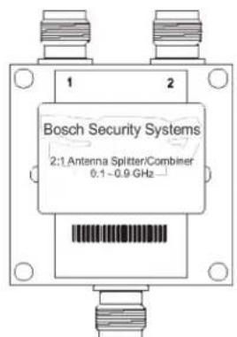
Model (CTN) No. APS1 COMB_SPLT
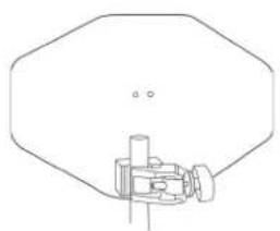
natural_image
Pure technical line drawing of a mechanical component without any text, numbers, or symbols
AB-2
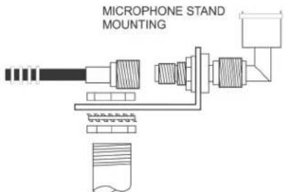
Bracket for 1/2 wave antenna with 10 ft. of coax
Model (CTN) No. AB-2
BTR Power Cords
North America Model (CTN) No.
PC-USA
U.K. Model (CTN) No.
PC-UK
European Model (CTN) No.
PC-EURO
BTR Intercom
Dummy Load
Telex type Model (CTN) No.
TP-3
| BTR Power Cords | CTC, BTR-80N CAN BUSTermination CableBP-800NM Rechargeable2200mAhr Nickel-Metalhydride battery pack | Model (CTN) No.CTC | |
| RTS type Model (CTN) No. | |||
| TP-3R | |||
| 2TX80N Dualtransmit connectorkit for BTR-80N | Model (CTN) No.2TX80N-KIT | BC-800 NM4 4-Slot SmartCharger with four (4)BP-800NM battery packs | |
| SA Relay plugadapter | CONN, PCB 2-PIN2MM, BLK, Printed 1-22862046 | North America | Model (CTN) No.BC800NM4 |
| DC-LP LockingD.C. plug | Plug D.C. 5.5 X 2.5650102 | Euro | Model (CTN) No.BC800NM4E |
| BLC, BTR-80NLink Cable | Model (CTN) No.BLC | BC-800NM Single-slotSmart Charger withBP-800NM battery pack | |
| CTC, BTR-80N CAN BUSTermination Cable | Model (CTN) No.CTC | North America | Model (CTN) No.BC800NM |
| CTC, BTR-80N CAN BUS120 Ω Termination | Model (CTN) No.CAN-T | Euro | Model (CTN) No.BC800NME |
| BP-700 TR Battery pack,alkaline (batteries notincluded) | Model (CTN) No.BP-700 | ||
Beltpack: 1/4 - Wave Antenna
| Model (CTN) No. | Band Color | Frequency Coverage of Antenna | Frequency Band Designators | ||||||||||||
| F H | A B | C D | E 1 2 | 3 4 5 | 6 | ||||||||||
| BPA-1 Violet 425.0 - 488.0 MHz | |||||||||||||||
| BPA-2 Black 485.0 - 553.9 MHz X X X X | |||||||||||||||
| BPA-3 Yellow 554.0 - 635.9 MHz X X X X | |||||||||||||||
| BPA-4 Green 636.0 - 725.9 MHz X X X X X | |||||||||||||||
| BPA-5 Red 726.0 - 826.0 MHz | |||||||||||||||
| BPA-6 Blue 826.0 - 930.0 MHz | |||||||||||||||


natural_image
Technical line drawing of a cylindrical mechanical component with flanges and a base (no text or symbols)Base Station: Flexible Ground Independent Dipole Antenna
| Model (CTN) No. | Band Color | Frequency Coverage of Antenna | Frequency Band Designators | ||||||||||||
| F H | A B | C D E | 1 2 3 | 4 5 6 | |||||||||||
| FA-RW-RS | Red/ White | 470 - 550 MHz | X X | X | |||||||||||
| FA-YW-RS | Yellow/ White | 525 - 610 MHz | X X | X X | |||||||||||
| FA-GW-RS | Green/ White | 610 - 710 MHz | X X | X X X | |||||||||||
| FA-BW-RS | Blue/ White | 710 - 880 MHz | X | ||||||||||||
Three (3) Band Base Stations
Identifying a Three (3) Band Unit
Three (3) band base station normally have an 18MHz wide receive range of 650-668MHz. These three (3) band base stations are designated by having a “3” in the second digit of the two digit band code that is on a label on the rear panel of the unit.
Regulatory Changes and the Three Band
There are two channel map configurations in a three band base station. One for the US/Canada and one for the rest of the world. At one time (before October, 2018) there was only one channel map for a three band unit. but due to regulatory changes in the US/Canada an additional map was produced and installed in three band base stations. The result of the FCC incentive auction in regard to wireless intercom was the following:
- Only 10MHz (653-663MHz) may be used for wireless intercom in the range 616MHz to 698MHz.
- Three band beltpack transmit power must be reduced to 20mW EiRP for US and Canadian units.
Since the three band units are made for worldwide customers, the 18MHz range is the default shipped, therefore a US or Canadian user must set a base station to the new US channel map in order for the base's channel map to match the US three band beltpack's channel map. The US three band beltpacks only have the new US channel map in them.
NOTE: Only Canadian users of the three band base station needs to change the channel map of the base station to the US channel map!
Changing Channel Maps
A three band base station may be changed from a normal channel map to a US channel map and back again with the press of a couple of buttons. The current channel map setting is remembered by the unit even if power is removed.
- At the base station's main operating screen press and hold [SET]+[UP] buttons until the switching band text is displayed.
The three band map the unit is switching to will be displayed. - Release the buttons when switching three band text is shown.
Unit will reboot and display one of the following channel map versions on boot:
X30001 = Normal three band channel map
X3U001 = US three band channel map
(where X is the current transmit band of the base station.)
Bosch Security Systems, LLC
12000 Portland Avenue South
Burnsville, MN 55337 U.S.A.
- BTR-80N, TR-80N, TR-82N Professional Wireless Intercom System
- PROPRIETARY NOTICE
- COPYRIGHT NOTICE
- WARRANTY AND SERVICE INFORMATION
- CUSTOMER SUPPORT
- DISCLAIMER
- Important Safety Instructions
- Table of Contents
- INTRODUCTION......9
- INSTALLATION ....19
- OPERATION 25
- General Description
- System Features
- Controls and Connections
- BTR-80N - Rear Panel
- Specifications
- Overall
- Transmitter
- Receiver
- TR-80N - Top Panel
- TR-82N - Top Panel
- Transmitted
- Unpacking
- BTR-80 N
- Quantity Description
- TR-80N, TR-82N
- Antenna Connection
- Antenna Polarization
- Distance between Antennas
- Antenna Placement
- 1
- 2
- 3
- Improving Reception and Increasing Range
- BTR-80N
- Operation
- Basic Operational Description
- System Quick Start
- Transmit and Receive Antennas
- 2-Wire Intercom Ports
- 4-Wire Intercom Ports
- Auxiliary Input/Output
- Base Station Link
- Stage Announce (SA)/Relay
- Base Station Link Jack
- Program Jack
- Powering the Base Station
- Start Up Screen
- Status Screen
- RSSI Screen
- Group/Channel Select Screen
- Group/Channel Screen
- Group/Frequency Screen
- Frequency Edit (User-Defined Groups Only)
- Base Main Settings
- TALK Button
- Channel Select Button
- Local Headset Volume and Gain
- Base Transmitter Power
- Squelch Settings
- Stage Announce Level
- Antenna Power
- CAN Bus Number
- Intercom Settings
- 2-Wire Intercom
- 4-Wire Intercom
- Auxiliary Settings
- ClearScan
- Lockout
- Copy
- 1st Use Defaults
- Factory Default
- Connection of Multiple Base Stations with the Link Cables
- These features are:
- Over-the-Air Data Links
- Master and Servant Base Stations
- CAN bus
- Base Station Link Configurations
- Wireless Talk-Around Audio Only
- Link Overview
- Setup
- WTA and a SINGLE CAN Bus Network
- NOTE:
- WTA and Several CAN Bus Networks
- TR-80N/82N
- Battery Installation
- WARNING:
- Headset Connection
- Sidetone
- On/Off and Volume Control
- Audio Channel Select Button
- Stage Announce (SA)
- Wireless Talk Around (WTA)
- Groups and Channels
- Transmit Frequency
- Receive Frequency
- Microphone Gain
- Battery Display
- Low Battery Alert Tone
- Transmit Power
- Changing the Transmit Power Setting
- Squelch Screen
- Transmit Mode Screen
- LEDs Off/On
- Software Version/Band
- ClearScan™
- Lock Out
- First Use Default
- Factory Reset
- RF Monitor Screen
- Setting Beltpack ID
- Wireless Talk-Around (WTA)
- Battery Percentages
- Headphone Options:
- Auxiliary Input:
- TR-80N Beltpack Screen
- Flowchart
- Frequency Bands
- North America
- Europe
- Band Pairing for Systems
- Frequency Plan
- Battery Information
- The use of low cost carbon-zinc batteries is NOT recommended.
- Battery Warnings
- Battery Life
- TR-80N
- TR-82N
- Cold Temperatures and Batteries
- 2-Wire Systems Specification
- RTS
- ClearCom
- Certificate Information
- FCC
- Mandatory Safety Instructions to Base Station Installers and Users.
- Canada Radio Certification
- Accessories and Replacement Parts
- ALP-700
- ALP-450
- ALP-600
- Antenna Cables
- APS1 COMB\_SPLT
- BTR Power Cords
- BTR Intercom
- Dummy Load
- Three (3) Band Base Stations
- Identifying a Three (3) Band Unit
- Regulatory Changes and the Three Band
- Changing Channel Maps
- Bosch Security Systems, LLC
Brand : RTS
Model : BTR-80N
Category : Intercom