FBT-3000 - Generator Full Boar - Free user manual and instructions
Find the device manual for free FBT-3000 Full Boar in PDF.

| Brand | Full Boar |
| Model | FBT-3000 |
| Product Type | Portable Generator |
| Power Output (Rated) | 3000 Watts |
| Power Output (Peak) | 3500 Watts |
| Fuel Type | Gasoline |
| Fuel Tank Capacity | 4.5 Gallons (17 L) |
| Run Time at 50% Load | 10 Hours |
| Engine Type | 4-Stroke, OHV |
| Starting System | Recoil Start |
| Voltage | 120V / 240V |
| Outlets | 2x 120V GFCI Duplex, 1x 240V Twist Lock |
| Dimensions (L x W x H) | 24 x 18 x 20 inches |
| Weight | 88 lbs (40 kg) |
| Noise Level | 68 dB at 23 ft (7 m) |
| Oil Capacity | 0.6 Quarts (0.57 L) |
| Spark Plug | F7TC or equivalent |
| Maintenance | Change oil every 40 hours; clean air filter every 20 hours |
| Safety Features | Low oil shutdown, overload protection, GFCI outlets |
| Warranty | 2 Years Limited |
| Spare Parts Available | Yes (air filters, spark plugs, oil filters) |
| Repairability Index | 8.5 / 10 |
Frequently Asked Questions - FBT-3000 Full Boar
User questions about FBT-3000 Full Boar
0 question about this device. Answer the ones you know or ask your own.
Ask a new question about this device
Download the instructions for your Generator in PDF format for free! Find your manual FBT-3000 - Full Boar and take your electronic device back in hand. On this page are published all the documents necessary for the use of your device. FBT-3000 by Full Boar.
USER MANUAL FBT-3000 Full Boar
text_image
FULL BOARMOBILE PETROL GENERATOR
• MAX POWER 2800 WATTS
• 2 X 240V OUTLET SOCKETS
• 5.6HP MOTOR
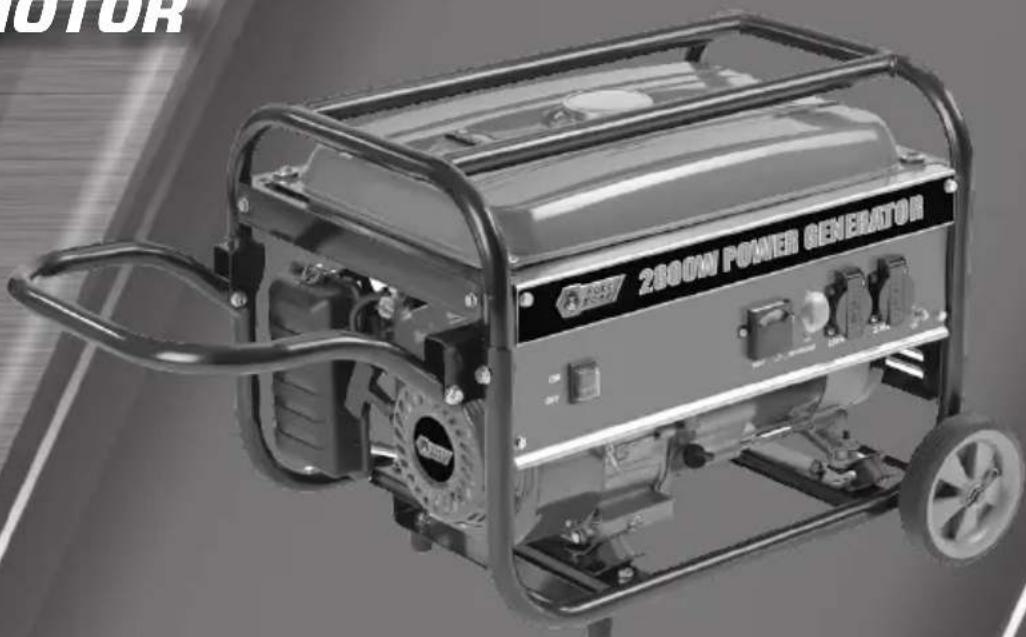
natural_image
Exterior view of a 2000W power generator with open circuit board (no visible text or symbols beyond branding)INSTRUCTION MANUAL
WARNING: Read all safety warnings and all instructions. Failure to follow the warnings and instructions may result in electric shock, fire and/or serious injury. Save all warnings and instructions for future reference.
SPECIFICATIONS - MODEL NO. FBT-3000
Engine Specifications:
Motor Power: 5.6HP
Engine Type: 4 Stroke, Air Cooled
Fuel Type: 91 RON Unleaded Petrol
Fuel Tank Capacity: 15 litres
Engine Capacity: 208cc
Engine Speed: 3000/min ^-1
Oil Type: 4 Stroke SAE30, 10W30
Oil Tank Capacity: 600ml
Spark Plug: LD F7RTC
Generator Specifications:
AC Output: 230-240Vac-50Hz
Continuous Power: 2,300W
Max. Power: 2,800W
Phase: Single
Weight: 41.5kg
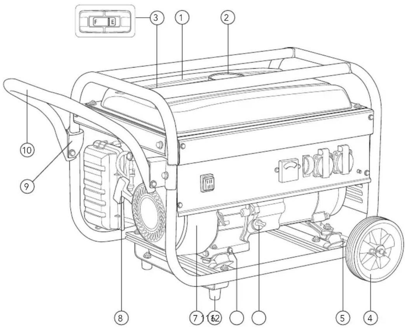
KNOW YOUR PRODUCT
text_image
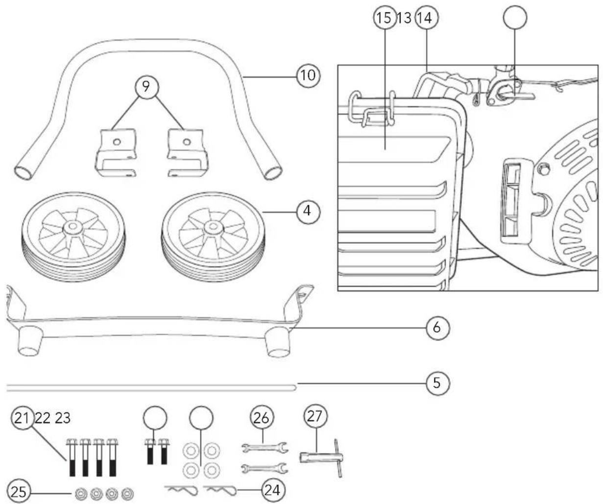
Technical diagram of a portable power grid generator with numbered components and control panel labelsKNOW YOUR PRODUCT (cont.)
text_image
Technical diagram of a mechanical assembly with numbered parts and exploded view, including components like rollers, gears, and tools.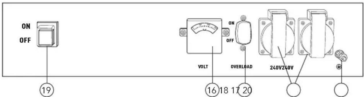
text_image
ON OFF 19 VOLT ON OFF 16 18 17 20 OVERLOAD 240V240V- Fuel tank 15 L
- Fuel tank cap
- Fuel gauge
- Wheel
- Axle
- Foot
- Powerful 4 stroke motor
- Recoil starter
- Push bar holder
-
Push bar
-
Oil filler cap
- Oil drain plug
- Choke lever
- Fuel tap
- Air filter
- Voltmeter
- 2 x 240V 10A socket
- Overload switch
- On/ Off switch
-
Earth connection
-
Screws size M8 x 40
- Screws size M8 x 16
- Washers for wheels
- Securing P-clips for wheels
- Nuts M8
- 10/12mm Spanners
- Spark plug spanner
TABLE OF CONTENTS
SPECIFICATIONS...... Page 02
KNOW YOUR PRODUCT...... Page 02
INTRODUCTION...... Page 05
SAFETY INSTRUCTIONS...... Page 05
UNPACKING......Page09
RISKS...... Page 10
AUTOMATIC VOLTAGE REGULATOR (AVR)...... Page 13
ASSEMBLY...... Page 14
PREPARATION...... Page 15
OPERATION...... Page 16
MAINTENANCE...... Page 18
TROUBLE SHOOTING...... Page 20
DESCRIPTION OF SYMBOLS...... Page 21
CONTENTS...... Page 22
WARRANTY...... Page 24
INTRODUCTION
Congratulations on purchasing a Full Boar Mobile Petrol Generator.
Your Full Boar Generator FBT-3000 has been designed for supplying 240V output power. The generator has inbuilt Automatic Voltage Regulator for stable power supply. Intended usage include, Leisure, camping, household mains backup and light trade use.

WARNING! Oil has been drained for shipping. Failure to fill engine sump with oil before starting the engine may result in permanent damage and will void warranty.
SAFETY INSTRUCTIONS

WARNING! When using mains-powered equipment, basic safety precautions, including the following, should always be followed to reduce risk of fire, electric shock, personal injury and material damage.
Read and understand the manual prior to operating this tool.
Save these instructions and other documents supplied with this tool for future reference.
ELECTRICAL SAFETY
Using an Extension Lead
Extension leads should be ordinary or heavy duty depending on the application, of appropriate current rating, and in any case not less than 1 mm^2 cross-section of conductor, and must incorporate an earthing conductor to ensure that there is no voltage difference between the generating set and any equipment powered by the generating set..
SAFETY WARNINGS FOR GENERATORS
- Do not operate in a hazardous location. Such areas include where there is a risk of explosion of petrol fumes, leaking gas or explosive dust.
- Do not operate in a confined area. Exhaust gases, smoke or fumes could reach dangerous concentrations.
- The output of this generator is potentially lethal. The generator should not be connected to a fixed electrical installation except by an appropriately licensed person.
- Protect your generator. This generator is NOT Weatherproof and should not be exposed to direct sunlight, high ambient temperature and damp, wet or high humidity conditions.
- Do not smoke while refuelling. This is potentially dangerous as it may ignite the fuel and cause an explosion.
- Take care not to spill fuel. When refuelling the generator ensure that the motor has been switched off. Prevent the spilling of fuel as this may also ignite with the hot motor. Never refuel whilst the engine is running.
- Be careful where you store the generator. Store the generator in a dry area away from inflammable liquids.
- Keep your distance. The generator emits exhaust fumes. As a safety precaution do not stand close to the unit whilst it is in operation. Ensure bystanders also keep their distance.
- Ensure the generator has oil. Before commencing the generator, ensure that the unit has been filled with eg. SAE30 4 stroke oil.
- Never fill fuel tank indoors. Never fill fuel tank when engine is running or hot. Do not smoke when filling fuel tank.
- Never refuel when the generator is running. Switch the generator to the OFF position prior to removing the fuel cap and refuelling.
- Engine speed has been factory set to provide safe operation. Tampering with the engine speed adjustment could result in overheating of the attachments and could cause a fire. Never attempt to "speed up" the engine to obtain more performance. Both the output voltage and frequency will be thrown out of standard by this practice endangering attachments and the user.
- You must unplug any load from the generator before starting and stopping to prevent permanent damage to the appliances.

WARNING! Persons who are fitted with a heart pacemaker, or similar medical conditions should take care when using this device.
UNPACKING
If you find anything wrong, do not operate the generator until parts have been replaced or the fault has been rectified. Failure to do so could result in serious personal injury.
RISK OF ELECTROCUTION AND FIRE
| Hazard What could | happen How to prevent it | |
| Improper storage of extension cord. | Extension cord can come into contact with hot engine parts resulting in damage. Using a damaged extension cord can result in electrocution or death. | Remove extension cord from the generator and store separately away from generator. |
| Operation of generator in rain, wet, icy, or flooded conditions. | Water is an excellent conductor of electricity! Water which comes in contact with electrically charged components can transmit electricity to the frame and other surfaces, resulting in electrical shock to anyone contacting them. | Operate generator in a clean, dry, well ventilated area. Make sure hands are dry before touching unit. |
| Placing generator on or against highly conductive surface, such as a steel walkway or metal roof. | Accidental leakage of electrical current could charge conductive surfaces in contact with the generator. | Place generator on low conductivity surface such as a concrete slab.ALWAYS operate generator a minimum of 2 meters from any conductive surface. |
| Operation of unit when damaged, or with guards or panels removed. | Attempting to use the unit when it has been damaged, or when it is not functioning normally could result in fire or electrocution.Removal of guarding could expose electrically charged components and result in electrocution. | Do not operate generator with mechanical or electrical problem.Have unit repaired by an Authorized Service Centre.Do not operate generator with protective guarding removed. |
| Hazard What could happen How to prevent it | ||
| Operation of generator in careless manner | All sources of energy include the potential for injury. Unsafe operation or maintenance of your generator could lead to serious injury or death to you or others. | Review and understand all of the operating instructions and warnings in this manual.Become familiar with the operation and controls of the generator. Know how to shut it off quickly.Equip area of operation with a fire extinguisher certified to handle gasoline or fuel fires.Keep children or others away from the generator at all times. |
| Operating generator | Generator will not operate properly and will cause damage to the generator and could cause serious injury or death to you or others. | Never operate generator while suspended or in an unlevel position. Always operate generate on a flat, level surface. |
RISK OF BREATHING - INHALATION HAZARD
| Hazard What could happen How to prevent it | ||
| Gasoline engines produce toxic carbon monoxide exhaust fumes | Breathing exhaust fumes will cause serious injury or death. | Operate generator in clean, dry, well ventilated area. Never operate unit in enclosed areas such as garages, basements, storage, sheds, or in any location occupied by humans or animals. Keep children, pets and others away from area of operating unit. |
RISK OF MOVING PARTS
| Hazard What could happen How to prevent it | ||
| Contact with moving parts can result in serious injury | The generator contains parts which rotate at high speed during operation. These parts are covered by guarding to prevent injury. | Never operate generator with guarding or cover plates removed. Avoid wearing loose fitting clothing or jewellery which could be caught by moving parts. |
AUTOMATIC VOLTAGE REGULATOR (AVR)
This generator has been fitted with AVR Technology which provides automatic voltage regulated power for a continuous uninterrupted stable power supply.
The AVR maintains a regulated AC output and reacts quickly to the rapid changes in load/voltage, therefore reducing the possibility of damage to the generator and the attached equipment.
It is strongly suggested to use a surge protector on the output of the generator for sensitive equipment.
Many products have peak power requirements that are higher than their operating rating. Use the below as a guide for using appliances
What can I use this generator for?
Refrigerator & Pumps.... 1200W
Power tools, Household appliances.... 1800W
Heating appliances, Kettle, Cooking,
Heaters, Lights....2200W
ASSEMBLY

WARNING! During assembly ensure the generator is switched OFF
- Carefully remove contents from the packaging.
- Select a firm, level surface on which to assemble the generator
Wheels
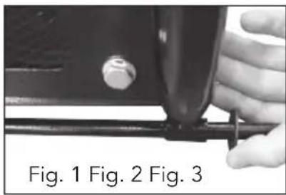
- Push the axle (5) through the generator frame, place a washer (23) on the outside (Fig. 1).
- Place a wheel on each end of the axle (5) followed by a washer (23) (Fig. 2).
- Push the P-clip (24) through the hole on the axle (5) and rotate to locate and ensure it is secure (Fig. 3).
natural_image
Close-up of a hand adjusting a metal pipe fitting (no text or symbols visible)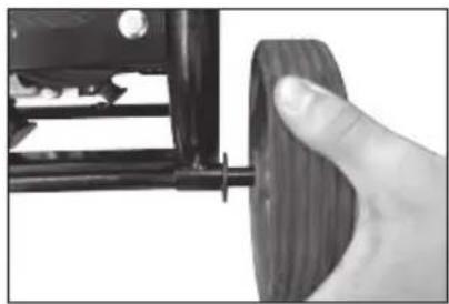
natural_image
Close-up of a hand holding a wooden rolling pin next to a mechanical component (no visible text or symbols)
natural_image
Close-up of a hand adjusting a tire wheel component (no visible text or symbols)Handle
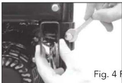
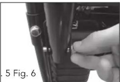
- Attach the two push bar holders (9) to the rear frame of the generator, using the supplied bolts (21) (Fig. 4).
- Align the holes in the push bar with the holes in the push bar holder and secure with the supplied nuts (25) and bolts (21) (Fig. 5 & 6).
natural_image
Close-up of hands using a wrench to adjust or install a mechanical component (no visible text or symbols)Fig. 4 Fig
natural_image
Close-up of a hand adjusting a small mechanical component (no visible text or symbols)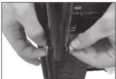
natural_image
Close-up of hands adjusting a small mechanical component (no visible text or symbols)Foot bracket
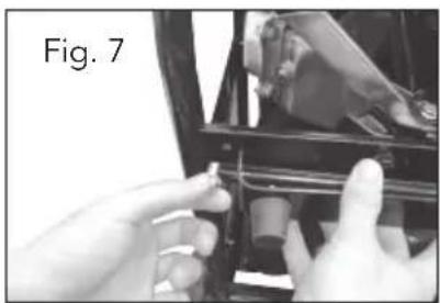
- Align the holes in the foot bracket with the holes in the bottom plate, towards the front of the generator.
- From the bottom of the generator insert one of the supplied bolts (22) (Fig. 7) and secure it with a nut (25) from the top of the frame.
natural_image
Close-up of hands installing or adjusting a mechanical component (no visible text or symbols)PREPARATION
Checking the oil

IMPORTANT. Ensure that the engine is fully filled with oil. When leaving the factory the generator is emptied of oil in preparation for shipping.
The engine of this generator needs to fill with engine oil.
Make sure the engine is filled with quality 4 stroke oil, SAE 30 recommended.
- Before filling with the oil make sure it is on a level surface and the unit has been switched OFF
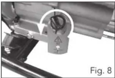
- Remove the oil filler cap (11) by rotating the cap anti-clockwise (Fig. 8) and check the level on the dip stick.
- Wipe the dip stick with a cloth and enter the dip stick into the crank case.
Do not screw it in and check the level. - Fill the engine crank case with the oil (use a funnel, do not tip generator) until the oil is at the upper level on the dip stick (Fig. 9).
Note. This motor is fitted with a low oil sensor. If the oil level is too low the motor will stop or the motor will not start. It is advised to check the oil level regularly.
natural_image
Close-up of a mechanical component with a central circular feature and warning symbol, labeled Fig. 8 (no readable text or symbols on the object itself)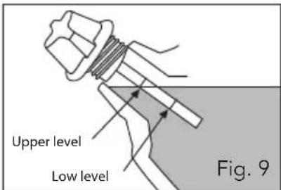
text_image
Upper level Low level Fig. 9Fuelling the Generator
Note. The engine will not start if the generator is not filled with oil or the level is low.

IMPORTANT. Ensure that the engine is fully filled with oil. When leaving the factory the generator is emptied of oil in preparation of shipping.
- Ensure the generator is switched OFF
-
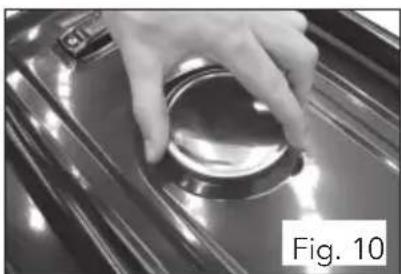
Remove the fuel cap (2) (Fig. 10), and view the fuel gauge (3) to check fuel level (Fig. 11).
-
Pour the required amount of fuel into the tank from an approved fuel container. Do not over fill
-
Replace the fuel cap and clean up any spillages.
natural_image
Close-up of a hand pressing down on a metallic surface, labeled 'Fig. 10' (no other text or symbols visible)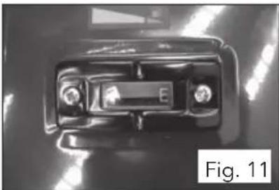
natural_image
Close-up of a car front panel with visible battery and screw holes (no text or symbols)
WARNING! Do not refill tank while engine is running or is hot.
WARNING! Be careful not to admit dust, dirt water or other foreign objects into the tank.
WARNING! Wipe off any spilt fuel before starting.
WARNING! The generator should be located in an open area when refuelling, do not refill in confined area.
OPERATION
Starting the Generator
- Before starting the unit, unplug equipment from the generator
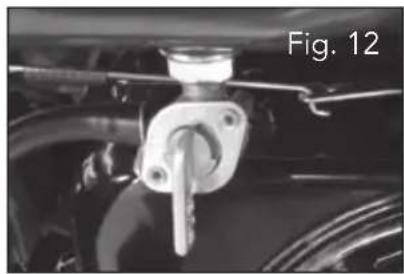
- Turn the fuel tap ON (Fig. 12).
- Switch the ON/OFF switch (19) to the ON position (Fig. 13).
- Turn the choke (13) to the cold start position (Fig. 14).
- Pull the recoil starter (8) (Fig. 15) slowly until you feel resistance, let it go back in the recoil. Then pull the recoil starter hard until the engine starts.
- Let the engine warm up, and move the choke lever (13) to the run position (Fig. 16).
natural_image
Close-up of a mechanical component with a metallic bracket and attached shaft, labeled 'Fig. 12' (no other text or symbols visible)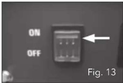
text_image
ON OFF Fig. 13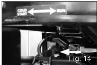
text_image
COLD START RUN Fig. 14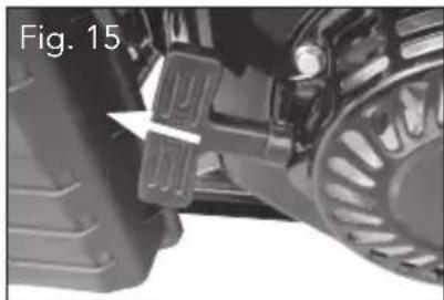
natural_image
Close-up of a vehicle's lower body and side legs, showing mechanical components and a highlighted section (no text or symbols)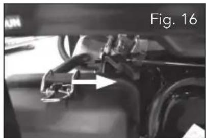
natural_image
Close-up of a mechanical component with a white arrow pointing to a section, labeled 'Fig. 16' (no readable text or symbols beyond label)Stopping the Generator
- Before stopping the generator, turn off any equipment.
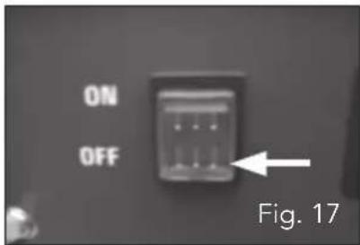
- Switch the ON/OFF switch (19) to the OFF position (Fig. 17).
- For transport or storage, turn the fuel tap (14) to the OFF position (Fig. 18).
text_image
ON OFF Fig. 17
natural_image
Close-up of a mechanical clamp or bracket component mounted on a vehicle (no visible text or symbols)OPERATION (cont.)
Overload
If the overload switch has tripped and cuts off the power, it may be due to overloading.
Overloading may not switch the Overload switch but it may shorten the service life of the generator.
Be sure that all appliances are in good working order before connecting them to the generator. If an appliance begins to operate abnormally, becomes sluggish, or stops suddenly turn "OFF" the generator.
If the overload keeps operating disconnect the appliance and examine it for signs of malfunction.
- Disconnect all appliance, reset the Overload (18) to ON
- Start the generator as describe in the previous section,
- Refit the appliance, if the Overload trips again then the equipment / appliance needs to be checked.
Any faulty equipment will need to be repaired by a suitable qualified person.
Connecting appliance/s to Generator
- Start the generator as detailed on page 12, "Starting the Generator"
- For multiple appliances the total power of the appliances must be less than the rating of the generator, max. power 2800W or 2300W continuous.
- Check the appliance is turned off.
- Plug the 3 pin plug into the 240V socket (17) of the generator
MAINTENANCE
Generator Maintenance
Your Generator should be kept clean and dry at all times. The generator should not be stored or operated in environments that includes excessive moisture, dust or any corrosive vapours. If these substances are on the generator, clean with a cloth or soft brush. Do not use a garden hose or anything with water pressure. Water may enter the cooling air slots and could possibly damage the generator.
Any faulty equipment will need to be repaired by a suitable qualified person.
Storage
If you are going to store your generator for more than 30 days, use the following information as a guide to prepare the generator for storage.
Never store generator with fuel in the tank indoors or in enclosed, poorly ventilated areas, where fumes can reach an open flame, spark or pilot light as on a furnace, water heater, clothes dryer or other gas appliances.
Ensure the fuel tank is fully drained of fuel.
Open the drain on the carburettor to drain the fuel totally from the bowl.
Check the fuel tap (14) is turned off.
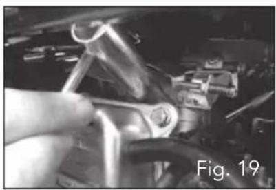
Spark plug cleaning or replacing
- Remove spark plug from the generator with the spark plug spanner (27) supplied (Fig. 19).
- Remove carbon deposits using a wire brush.
- Check for discolouration on the top of the spark plug. The standard colour should be a tan colour.
- Check the spark plug gap. The acceptable gap should be between 0.7 - 0.8mm (Fig. 20).
- If necessary replace with a new one.
Spark plug: LD F7RTC
natural_image
Close-up of a hand using a pliers to adjust or install components in a mechanical assembly (no visible text or symbols)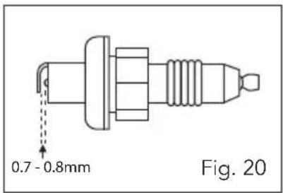
text_image
0.7 - 0.8mm Fig. 20MAINTENANCE (cont.)
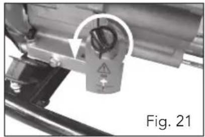
Engine oil replacement
-
Place generator on a level surface and start up the generator and run for several minutes.
-
Remove the oil filler cap (11) (Fig. 21).
-
Place a oil pan under the generator and remove the drain plug (12) (Fig. 22) so that all the oil can be completely drained.
-
Check the oil drain plug, gasket, and oil filler cap and o-ring. If damaged have these replaced.
-
Reinstall the oil drain plug. Add engine oil to the upper level of the dip stick. Recommended SAE 30 engine oil.
natural_image
Close-up of a mechanical component with a central lock and mounting bracket, labeled Fig. 21 (no readable text or symbols)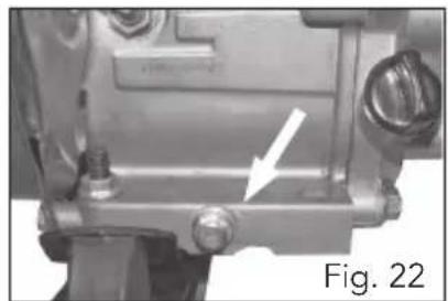
natural_image
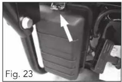
Mechanical component with a white arrow pointing to a small feature, labeled 'Fig. 22' (no readable text or symbols beyond label)Air filter cleaning & replacement
It is important to maintain an air filter (15) in good condition. Always keep the air filter clean.
-
Unclip the metal clip on the air filter housing (Fig. 23).
-
Remove the air filter (Fig. 24).
-
Wash the air filter in soapy water and allow to dry.
-
Replace the air filter back into the filter housing.
-
Secure the cover and return the clip to hold in place.
natural_image
Close-up of a black mechanical component with a white arrow pointing to a feature, labeled 'Fig. 23' (no readable text or symbols beyond label)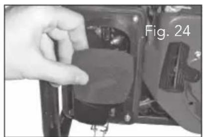
natural_image
Close-up of a hand holding a small electronic component, labeled 'Fig. 24' (no other text or symbols visible)TROUBLE SHOOTING
| Trouble Possible cause Suggested remedy | |
| Engine will not start | 1. Low on fuel or oil content 1a. Add Fuel (ensure fuel is fresh)1b. Fill oil in motor to correct level |
| 2. Generator not sitting on level ground. | |
| 3. On/Off switch in “Off” position | |
| 4. Faulty spark plug 4. Replace or clean spark plug | |
| 5. Choke in wrong position 5. Adjust choke accordingly | |
| 6. Fuel shut-off valve in closed position | |
| 7. Unit loaded during start-up 7. Remove load from unit | |
| 8. Spark plug wire loose 8. Attach wire to spark plug | |
| No electrical output | 1. Faulty receptacle 1. Have service centre replace receptacle |
| 2. Dirty or stale fuel in carburettor bowl. | |
| 3. Overload switch turned off 3. Lift to reset | |
| Repeated circuit breaker (Overload switch) tripping | 1. Overload 1. Reduce load |
| 2. Faulty cords or equipment 2. Check for damaged, bare, or frayed wires on equipment. Replace. | |
| 3. Check rating label of the appliance. |
DESCRIPTION OF SYMBOLS
| V | Volts | Hz | Hertz |
| ~ | Alternating current | W | Watts |
| /min | Revolutions orreciprocation per minute | No | No load speed |
| Hp | Horse power |  | Regulator compliance mark |
 | Use eye protection |  | Warning |
CARING FOR THE ENVIRONMENT

Power tools that are no longer usable should not be disposed of with household waste but in an environmentally friendly way. Please recycle where facilities exist. Check with your local council authority for recycling advice.

Recycling packaging reduces the need for landfill and raw materials. Reuse of recycled material decreases pollution in the environment. Please recycle packaging where facilities exist. Check with your local council authority for recycling advice.
CONTENTS
1 x Generator
2 x Wheels
1 x Push handle
2 x Push handle holders
1 x Axle
1 x Foot bracket
4 x Bolts size M8 x 40
2 x Bolts size M8 x 16
4 x Washers for wheels
2 x Securing P-clips for wheels
4 x Nuts M8
2 x 10/12 Spanners
2 x Spark plug spanner
1 x Instruction Manual
Distributed by:
Ozito Industries Pty Ltd
AUSTRALIA (Head Office)
1-23 Letcon Drive, Bangholme Victoria, Australia, 3175
Telephone: 1800 069 486
[Non-Text]
[Non-Text]
[Non-Text]
[Non-Text]
[Non-Text]
[Non-Text]
[Non-Text]
[Non-Text]
[Non-Text]
[Non-Text]
[Non-Text]
[Non-Text]
[Non-Text]
[Non-Text]
[Non-Text]
[Non-Text]
[Non-Text]
[Non-Text]
[Non-Text]
[Non-Text]
[Non-Text]
[Non-Text]
[Non-Text]
[Non-Text]
[Non-Text]
[Non-Text]
[Non-Text]
[Non-Text]
[Non-Text]
[Non-Text]
[Non-Text]
[Non-Text]
[Non-Text]
[Non-Text]
[Non-Text]
[Non-Text]
[Non-Text]
[Non-Text]
[Non-Text]
[Non-Text]
[Non-Text]
[Non-Text]
[Non-Text]
[Non-Text]
[Non-Text]
[Non-Text]
[Non-Text]
[Non-Text]
[Non-Text]
[Non-Text]
[Non-Text]
[Non-Text]
[Non-Text]
[Non-Text]
[Non-Text]
[Non-Text]
[Non-Text]
[Non-Text]
[Non-Text]
[Non-Text]
[Non-Text]
[Non-Text]
[Non-Text]
[Non-Text]
[Non-Text]
[Non-Text]
[Non-Text]
[Non-Text]
[Non-Text]
[Non-Text]
[Non-Text]
[Non-Text]
[Non-Text]
[Non-Text]
[Non-Text]
[Non-Text]
[Non-Text]
[Non-Text]
[Non-Text]
[Non-Text]
[Non-Text]
[Non-Text]
12
19
(No text)
[Non-Text]
[Non-Text]
[Non-Text]
[Non-Text]
19
[Non-Text]
[Non-Text]
[Non-Text]
[Non-Text]
[Non-Text]
[Non-Text]
[Non-Text]
[Non-Text]
[Non-Text]
[Non-Text]
[Non-Text]
[Non-Text]
[Non-Text]
[Non-Text]
[Non-Text]
[Non-Text]
[Non-Text]
[Non-Text]
[Non-Text]
[Non-Text]
[Non-Text]
[Non-Text]
[Non-Text]
[Non-Text]
[Non-Text]
[Non-Text]
[Non-Text]
[Non-Text]
[Non-Text]
[Non-Text]
[Non-Text]
[Non-Text]
[Non-Text]
[Non-Text]
[Non-Text]
[Non-Text]
[Non-Text]
[Non-Text]
[Non-Text]
[Non-Text]
[Non-Text]
[Non-Text]
[Non-Text]
[Non-Text]
[Non-Text]
[Non-Text]
[Non-Text]
[Non-Text]
[Non-Text]
[Non-Text]
[Non-Text]
[Non-Text]
[Non-Text]
[Non-Text]
[Non-Text]
[Non-Text]
[Non-Text]
[Non-Text]
[Non-Text]
[Non-Text]
[Non-Text]
[Non-Text]
[Non-Text]
[Non-Text]
[Non-Text]
[Non-Text]
12
19
(No text)
[Non-Text]
[Non-Text]
[Non-Text]
[Non-Text]
[Non-Text]
[Non-Text]
[Non-Text]
[Non-Text]
WARRANTY
YOUR WARRANTY FORM SHOULD BE RETAINED BY YOU AT ALL TIMES. IN ORDER TO MAKE A CLAIM UNDER THIS WARRANTY YOU MUST RETURN THE PRODUCT TO YOUR NEAREST BUNNINGS WAREHOUSE (see www.bunnings.com.au or www.bunnings.co.nz for store locations) WITH YOUR BUNNINGS REGISTER RECEIPT. PRIOR TO RETURNING YOUR PRODUCT FOR WARRANTY PLEASE TELEPHONE OUR CUSTOMER SERVICE HELPLINE:
Australia 1800 069 486 New Zealand 0508 069 486
TO ENSURE A SPEEDY RESPONSE PLEASE HAVE THE MODEL NUMBER AND DATE OF PURCHASE AVAILABLE. A CUSTOMER SERVICE REPRESENTATIVE WILL TAKE YOUR CALL AND ANSWER ANY QUESTIONS YOU MAY HAVE RELATING TO THE WARRANTY POLICY OR PROCEDURE.
1 YEAR REPLACEMENT WARRANTY
Your product is guaranteed for a period of 12 months from the original date of purchase. If a product is defective it will be replaced in accordance with the terms of this warranty. Warranty excludes consumable parts, for example: wheels, bearings.
The benefits provided under this warranty are in addition to other rights and remedies which are available to you under law. The warranty covers manufacturer defects in materials, workmanship and finish under normal use.
Our goods come with guarantees that cannot be excluded under Australian Consumer law & Consumer Guarantees Act 1993 (NZ). You are entitled to a replacement or refund for a major failure and to compensation for other reasonably foreseeable loss or damage. You are also entitled to have the goods repaired and replaced if the goods fail to be of acceptable quality and the failure does not amount to a major failure.
WARRANTY EXCLUSIONS
The following actions will result in the warranty being void.
• If the tool has been operated on a supply voltage other than that specified on the tool.
- If the tool shows signs of damage or defects caused by or resulting from abuse, accidents or alterations.
• Failure to perform maintenance as set out within the instruction manual.
• If the tool is disassembled or tampered with in any way.
• The warranty excludes damage resulting from product misuse or product neglect.
This warranty is given by Ozito Industries Pty Ltd.
ABN: 17 050 731 756
Ph.1800 069 486
Australia/New Zealand (Head Office)
1-23 Letcon Drive, Bangholme, Victoria, Australia 3175