
PrimeTest 100 - Measurement Seaward - Free user manual and instructions
Find the device manual for free PrimeTest 100 Seaward in PDF.


| Product Type | Portable Appliance Tester (PAT) |
| Brand | Seaward |
| Model | PrimeTest 100 |
| Measurement Functions | Insulation resistance, earth bond resistance, lead polarity test, full IEC lead test |
| Display | Backlit LCD graphical display |
| Power Supply | Built-in rechargeable Li-ion battery, mains adapter included |
| Dimensions (H x W x D) | 240 x 160 x 80 mm |
| Weight | 1.2 kg (approx.) |
| Safety Rating | CAT II 300V |
| Memory | Stores up to 1000 test results |
| Data Transfer | USB interface for PC download |
| Auto-Test Sequences | Yes, with pass/fail indicators |
| Test Lead Kit | Included (BS1363, SCHUKO, etc.) |
| Calibration | Recommended annually |
| Operating Temperature | 0°C to 40°C |
| Storage Temperature | -20°C to 60°C |
| Humidity | Up to 80% non-condensing |
| IP Rating | IP54 (splash and dust resistant) |
| Accessories Included | Test leads, mains lead, carrying case, USB cable |
| Languages | EN, FR, DE, ES, IT, NL |
Frequently Asked Questions - PrimeTest 100 Seaward
User questions about PrimeTest 100 Seaward
0 question about this device. Answer the ones you know or ask your own.
Ask a new question about this device
Download the instructions for your Measurement in PDF format for free! Find your manual PrimeTest 100 - Seaward and take your electronic device back in hand. On this page are published all the documents necessary for the use of your device. PrimeTest 100 by Seaward.
USER MANUAL PrimeTest 100 Seaward
Operating Instructions
PrimeTest 100
Operating Instructions

SEAWARD
Bracken Hill
South West Industrial Estate
Peterlee
Co Durham
SR8 2SW
ENGLAND
Tel: +44(0)191 586 3511
www.seaward.com
sales@seaward.com
service@seaward.com
Part Number 344A550 Revision 8
© 2022 Seaward Electronic Ltd
PrimeTest 100 Operating Instructions
Limited Warranty & Limitation of Liability
SEAWARD Electronic Limited guarantees this product to be free from defects in material and workmanship under normal use and service for a period of 1 year. The period of warranty will be effective at the day of delivery.
(c) Copyright 2022
All rights reserved. Nothing from this edition may be multiplied, or made public in any form or manner, either electronically, mechanically, by photocopying, recording, or in any manner, without prior written consent from SEAWARD Electronic Limited. This also applies to accompanying drawings and diagrams.
Due to a policy of continuous development SEAWARD Electronic Limited reserves the right to alter the equipment specification and description outlined in this publication without prior notice and no part of this publication shall be deemed to be part of any contract for the equipment unless specifically referred to as an inclusion within such contract.
PrimeTest 100 Operating Instructions
Contents
1 Important Information 4
2 Introduction 7
3 Performing Tests 9
3.1 Checking a mains power outlet 9
3.2 Testing a Class I Appliance 11
3.3 Testing a Class II Appliance 13
3.4 Testing a mains cord 15
3.5 Testing an extension lead 17
4 Specification 19
5 Maintenance 20
6 Battery Check 20
6.1 Battery Replacement 21
7 Service and Calibration 22
1 Important Information
These operating instructions are intended for the use of adequately trained personnel.
The following symbols are used in these operating instructions and on the PrimeTest 100.

Caution, risk of electric shock. Indicates instructions must be followed to avoid danger to persons.

Caution, risk of danger. The operating instructions must be adhered to in order to avoid danger.
Before use, ensure unit is clean and dry; visually inspect all leads, connectors, and case. Any damage or wear must be rectified prior to use.
Disposal of old product

natural_image
Symbol of a trash bin with no text or labels, including a crossed-out box and a solid black rectangle below (no readable text or symbols)This product has been designed and manufactured with high quality materials and components that can be recycled and reused.
When this symbol is attached to a product it means the product is covered by the European Directive.
Please familiarise yourself with the appropriate local separate collection system for electrical and electronic products.
Please dispose of this product according to local regulations. Do not dispose of this product along with normal waste material. The correct disposal of this product will help prevent potential negative consequences for the environment and human health.
PrimeTest 100 Operating Instructions
| Part Number | |
| PrimeTest 100 unit | 344A910 |
| Standard Accessories | Part Number |
| Carry Case | 71G082 |
| Black Test Lead 1m | 347A002 |
| UK IEC mains cord 0.5m | 300A002 |
| Operating Instructions | 344A550 |
| Optional Accessories | Part Number |
| 230/110V Adaptor | 270A076 |
| 3 phase adaptor - 16A 4 pin 415V | 209A910 |
| 3 phase adaptor - 16A 5 pin 415V | 209A911 |
| 3 phase adaptor - 32A 4 pin 415V | 209A912 |
| 3 phase adaptor – 32A 5 pin 415V | 209A913 |
Full details and specifications can be found at www.seaward.com or by calling Seaward Sales on 0191 586 3511.
PrimeTest 100 Operating Instructions
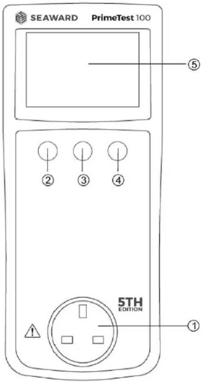
Figure 1. PrimeTest 100 Front View

Figure 2. PrimeTest 100 End View
PrimeTest 100 Operating Instructions
2 Introduction
The PrimeTest 100 is a hand held battery powered unit suitable for carrying out electrical safety checks on:
• Class I appliances
• Class II appliances
- IEC mains leads
- Extension leads
- Mains outlet wiring
Numbers shown in circles e.g. refer to figure 1 and figure 2 on page 6.
Test connections on the PrimeTest 100 are:
- Mains socket on front panel for connecting the appliance under test.
- 4mm socket on end panel for earth test probe
- IEC socket on end panel for mains cord testing.
User Interface
The LCD display shows test progress, results for individual tests and the overall test result for an appliance or mains cord.
Tests are initiated using the three push buttons:
Power ON/OFF = ② until two beeps are heard
Class I appliance test = ②
Class II appliance test = ③
Cord / extension lead test = ④
Note:
- A short press on keys, ② or ③ will cause the tests to be performed with the insulation voltage as set in the Setup Menu. A long press on keys, ② or ③ will cause
PrimeTest 100 Operating Instructions
the tests to be performed with the alternate insulation voltage from the Setup Menu. Eg 500V in Setup menu will result in a 250V insulation test.
- By Accessing the settings screen by holding keys 3 and 4 you will also be able to enter the Setup Menu and change the pass/fail limit on the earth continuity test between 0.1/0.2/0.3, change the insulation voltage between 500 and 250V and choose between British Standard (3.5mA and 0.5mA) or IET Code Of Practice (5mA and 5mA) Protective Conductor and Touch Current leakage limits.
Key 2 (Class1) to change Earth Continuity Limits
Key 3 (Class 2) to change Insulation Resistance Voltage
Key 4 (Cord) to change between leakage limits by standard.
- The PrimeTest 100 will automatically switch OFF after approximately 3 minutes if no keys are pressed. The auto switch-off is disabled during a power socket test.
- When a key is pressed to initiate a test sequence, the PrimeTest 100 will compare the type of appliance connected with the test sequence that has been selected, and where possible, will prompt the user if an inappropriate test has been selected. For example, if an IEC lead is connected between the front panel mains socket ①and the IEC socket on the end panel ⑦ and a Class 1 ②or Class II ③ appliance test is selected, the PrimeTest 100 will flash the Cord test ④ enunciator to indicate that the Cord test is the most appropriate test.
3 Performing Tests
Press keys Ⓞ to switch on the PrimeTest 100. When the unit is ready the display will be as shown below.

3.1 Checking a mains power outlet
Connect the IEC power cord to the PrimeTest 100 socket and plug into the mains power outlet to be tested.
If the mains socket wiring is correct the display will show.
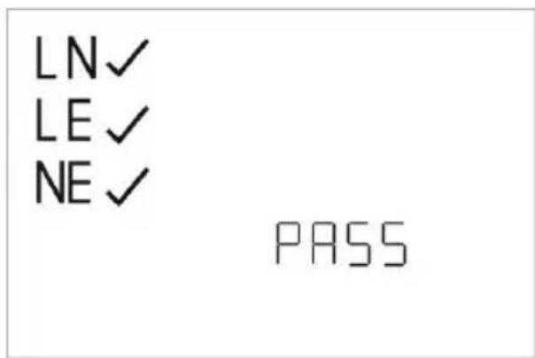
If the Live and Neutral in the socket wiring are reversed or there is a fault with the protective earth connection this is indicated by the display below.
PrimeTest 100 Operating Instructions

If there is a fault with the Neutral connection this is indicated by the display below.
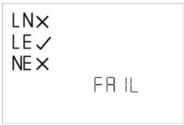
In the event of a test failure, disconnect the PrimeTest 100 from the supply and rectify the fault.

Do not leave the PrimeTest 100 permanently connected to a mains supply.
The auto switch-off function is disabled when the PrimeTest 100 is connected to a live mains socket. The unit will beep continually after 3 minutes to remind the user to disconnect from the mains socket.
3.2 Testing a Class I Appliance
- Visually inspect the appliance and mains cord for signs of damage.
- If the appliance passes a visual inspection proceed with the electrical tests.
- Plug the earth test lead into the 4mm socket on the PrimeTest 100 end panel.
- Plug the appliance into the PrimeTest 100 front panel mains socket ①
- Connect the earth test probe to an exposed metal part on the appliance.
- If the Appliance under test has an ON/OFF switch, make sure it is in the ON position.
- Press the Class I test key ②
- The PrimeTest 100 will now test the continuity of the protective earth.
- If you are testing a Class I item with no exposed earthed parts an option to accept the high continuity measurement is given. When the continuity test fails you can long press key ② and the continuity and show as NC (not checked) on the result screen.
- If the continuity measurement is greater than the set limit but <0.5ohms then the PrimeTest 100 will ask whether a long lead is attached. Press the key ② to record the result as a pass or the key ③ to record a fail.
× RPE 5.00 Ω
Riso <---- MΩ
I_LEAK<----mA^

- If the measured value is less than the pre-set pass/fail threshold, the measured value is displayed and the unit indicates a pass result, as shown below.

Refer to section 2 for changing the pass/fail limits
- The unit will proceed with the Insulation and Leakage tests.
Note: The power switch on the appliance under must be in the ON position to perform an insulation test. If no appliance is detected the PrimeTest 100 will display the following.
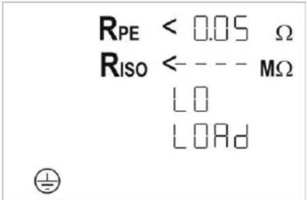
- Check that the appliance power switch is in the ON position. The test will automatically proceed if the appliance power switch is placed in the ON position.
- If the LO LOAD enunciator remains on the display, the load presented by the appliance may be too small for the PrimeTest 100 to detect. In this case, press the test key ② to continue.
- During the Insulation Test the PrimeTest 100 will display the selected test voltage.
- Refer to section 2 for changing the insulation resistance test voltage.
PrimeTest 100 Operating Instructions
- If the Insulation Resistance is greater than the factory set limit a tick is placed next to the Riso enunciator. If the Leakage current is less than the set limit a tick is placed next to the ILEAK enunciator.
• The PASS enunciator is illuminated.

3.3 Testing a Class II Appliance
- Visually inspect the appliance and mains cord for signs of damage.
- If the appliance passes a visual inspection proceed with the electrical tests.
- Plug the earth test lead into the 4mm socket on the PrimeTest 100 end panel.
- Plug the appliance into the PrimeTest 100 front panel mains socket ①
- Connect the earth test probe to an exposed metal part on the appliance.
- If the Appliance under test has an ON/OFF switch, make sure it is in the ON position.
- Press the Class II test key ③
- The PrimeTest 100 will now test Insulation Resistance and Leakage current.
Note: The power switch on the appliance under must be in the ON position to perform an insulation test. If no appliance is detected the PrimeTest 100 will display the following.
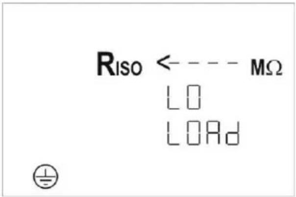
- Check that the appliance power switch is in the ON position. The test will automatically proceed if the appliance power switch is placed in the ON position.
- If the LO LOAD enunciator remains on the display, the load presented by the appliance may be too small for the PrimeTest 100 to detect. In this case, press the test key ③ to continue.
- During the Insulation Test the PrimeTest 100 will display the selected test voltage.
- If the Insulation Resistance is greater than the pre-set limit a tick is placed next to the Riso enunciator. Similarly, if the Leakage current is less than the pre-set limit a tick is placed next to the ILEAK enunciator.
• The PASS enunciator is illuminated.

- Should an earth path be picked up at the start of the test a message will appear asking to confirm that the EUT is Class II FE if it is and you wish to continue the test then press key ③ and the test will start. The value for the continuity will be shown but no pass/fail marker against it.
PrimeTest 100 Operating Instructions
It will then carry on with the following tests but automatically drop the test voltage to 250V for the insulation resistance.
Refer to section 2 for changing the pass/fail limits.
3.4 Testing a mains cord
- Visually inspect the mains cord and plug for signs of damage.
- Check that the correct fuse is fitted.
- If the cord passes a visual inspection proceed with the electrical tests.
- Plug the mains cord under test into the IEC socket ⑦ and the front panel mains socket on the PrimeTest 100.
- Press the cords test key ④
- The PrimeTest 100 will first test the continuity of the protective earth.
- If the measured value is greater than the pre-set limit a cross is placed next to the R_PE enunciator, a FAIL is indicated.
Note: The protective earth resistance will depend upon the length of the extension lead and the size (cross sectional area) of the cable. The measured value may be acceptable even if a cross is shown next to the R_E enunciator. For reference, typical resistance values for a variety of cable lengths and cross-sectional area are given in Table 1.
- If the continuity measurement is greater than the set limit but <0.5ohms then the PrimeTest 100 will ask whether a long lead is attached. Press the key ④ to accept the result as a pass or the key ③ to record a fail.
- The unit will proceed with the Insulation test.
- If the Insulation Resistance is lower than the pre-set limit a cross is placed next to the Riso enunciator and the test sequence is halted.
• If the Insulation Resistance is greater than the
PrimeTest 100 Operating Instructions
pre-set limit a tick is placed next to the Riso enunciator.
- The unit will proceed with the wiring test, checking the live and neutral conductors for short or open circuits or reversed connections.
- If the wiring is correct a tick is placed next to the cord enunciator, the GOOD enunciator is illuminated and a PASS is indicated for the sequence.
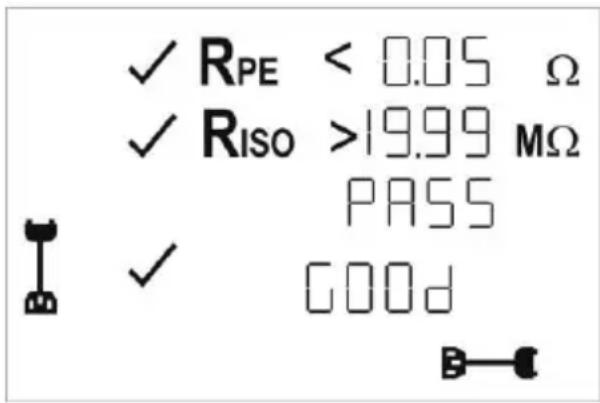
Refer to section 2 for changing pass/fail limits.
Note: If the tested cord has a wiring fault, one of the following enunciators will be illuminated in place of GOOD
- OPEN indicates that either the live or neutral conductor is broken (open circuit) or the plug top fuse has blown
- Short indicates that the live and neutral conductors are shorted together
- CROSS indicates that the live and neutral connections are crossed (live and neutral conductors reversed)
PrimeTest 100 Operating Instructions
3.5 Testing an extension lead
- Visually inspect the mains cord and plug for signs of damage.
- Check that the correct fuse is fitted.
- If the cord passes a visual inspection proceed with the electrical tests.
- Plug the supplied 0.5m red IEC lead into the IEC socket and into a mains outlet on the extension lead. Plug the mains plug of the extension lead into the front panel mains socket ① on the PrimeTest 100.
- The extension lead can now be tested in the same manner as an IEC as described above.
Note:
- The protective earth resistance will depend upon the length of the extension lead and the size (cross sectional area) of the cable. The measured value maybe be acceptable even if a cross is shown next to the R_PE enunciator.
- If the continuity measurement is greater than the set limit but <0.5ohms then the PrimeTest 100 will ask whether a long lead is attached. Press the key ④ to accept the result as a pass or the key ③ to record a fail.
Refer to section 2.2 for changing the pass/fail limits
PrimeTest 100 Operating Instructions
Table 1: Approximate resistance of protective earth conductors.
| Cord size / current rating | |||
| length | 0.5mm2/(3A) | 1.0 mm2/(10A) | 1.25 mm2/(13A) |
| 5m | 0.20 | 0.10 | 0.10 |
| 10m | 0.40 | 0.20 | 0.20 |
| 25m | 1.00 | 0.50 | 0.40 |
For further information on protective conductor resistance and testing of portable appliances can be found in the Code of Practise for In-service Inspection and Testing of Electrical Equipment published by the IET.
4 Specification
Earth Continuity
Accuracy* ± (5% + 2 digits) Test current 200mA minimum Test voltage 9V nominal
Insulation resistance
Accuracy ± (5% + 2 digits) Test voltage 500V Test current >1mA into 500kΩ Test current <2mA into 2kΩ
Leakage Current
Accuracy ± (5% + 2 digits) Test voltage 40V rms, 50Hz AC Test current <5mA into 2kΩ
Cord Test
Earth continuity, insulation resistance as above. Check for Live and Neutral open circuit, short circuit or reversed polarity.
*When used with Seaward test lead, Part Number 347A002
Pass/Fail limits settings
| Class I Class II Class II | FE | Cord/lead | ||
| Earth Continuity | 0.1/0.2/0.3 ohms | N/A N/A* 0 | 0.1/0.2/0.3 | ohms^ |
| Insulation Resistance | 1.0Mohm 2.0Mohm 2.0Mohm 2.0Mohm | |||
| Leakage | 3.5 or 5mA** | 0.5 or 5mA** | 0.5 or 5mA** | N/A |
Note
*Reads up to 20 ohms if Class 2 FE selected
^Reads up to 0.5 ohms if long lead selected
**Depending upon chosen standard, 3.5 and 0.5mA relate to BS EN 50699, 5mA limits relate to IET Code of Practice 5th Edition limits
PrimeTest 100 Operating Instructions
Environmental rating
IP Rating IP40
Operating temperature range 0^ C to 40^ C, without moisture condensation.
Storage temperature range -25^ to 65^ .
Note: Batteries should be removed prior to storage.
Overvoltage category 300V CAT II
5 Maintenance
Clean only with a dry cloth; do not use solvents. Before use, ensure unit is clean and dry; visually inspect all leads, connectors, and case. Any damage or wear must be rectified to preserve user safety.
Check the battery contacts and compartment are free of electrolytic contamination.
Any contamination of the battery contacts or compartment should be cleaned with a dry cloth.
Note: The PrimeTest 100 contains no user serviceable parts. If an Error warning should appear on the display please contact the manufacturer or an authorised Seaward Service Agent for advise.
6 Battery Check
The PrimeTest 100 is powered from a 6 AA cells which are checked before a test is performed. When the battery voltage is low the □ enunciator is illuminated. The unit will continue to perform within specification for a limited number of tests, dependent upon the type of the batteries fitted.
When the battery voltage reaches a level where the performance is affected the enunciator will flash and all test keys are disabled. The batteries must be replaced.
6.1 Battery Replacement

Before opening the PrimeTest 100 ensure that all test leads are disconnected.
- Switch off the unit by pressing and holding keys ② and . ③
- Disconnect the black test lead from 4mm test socket ⑥
- Disconnect the IEC mains cable from the IEC socket ⑦
- Disconnect the EUT mains cable from the EUT socket ①
- Place the PrimeTest 100 face down and release the captive screw in the battery compartment cover.
- Remove the battery compartment cover and remove the discharged batteries.
- Insert the replacement batteries into the battery compartment ensuring that the battery polarity matches the marking on the inside of the battery compartment.
- Relocate the battery cover over the battery compartment and fasten in position with the battery cover captive screw.
7 Service and Calibration
To maintain the specified accuracy of the measurement results, the instrument must be recalibrated at regular intervals by either the manufacturer or an authorised Seaward Service Agent. We recommend a recalibration period of one year.
For help or advise on Service and Calibration contact:
Service Department Seaward Electronic Bracken Hill South West Industrial Estate Peterlee Co Durham SR8 2SW England
Tel: 0191 586 3511 Email: service@seaward.com Web: www.seaward.com


- Operating Instructions
- PrimeTest 100
- SEAWARD
- PrimeTest 100 Operating Instructions
- Limited Warranty & Limitation of Liability
- Copyright 2022
- Contents
- Important Information
- Disposal of old product
- Introduction
- Numbers shown in circles e.g. refer to figure 1 and figure 2 on page 6.
- User Interface
- Note:
- Performing Tests
- Checking a mains power outlet
- Testing a Class I Appliance
- Testing a Class II Appliance
- Testing a mains cord
- Testing an extension lead
- Specification
- Cord Test
- Note
- Environmental rating
- Note: Batteries should be removed prior to storage.
- Maintenance
- Battery Check
- Battery Replacement
- Before opening the PrimeTest 100 ensure that all test leads are disconnected.
- Service and Calibration
Brand : Seaward
Model : PrimeTest 100
Category : Measurement