
ANI-88HDRH - Router A-NeuVideo - Free user manual and instructions
Find the device manual for free ANI-88HDRH A-NeuVideo in PDF.


| Product Type | Router |
| Brand | A-NeuVideo |
| Model | ANI-88HDRH |
| Wireless Standard | 802.11ac |
| Maximum Speed | 1200 Mbps |
| Frequency Bands | 2.4 GHz and 5 GHz |
| Ethernet Ports | 4 x LAN (10/100/1000 Mbps), 1 x WAN |
| Dimensions (W x D x H) | 200 x 150 x 40 mm |
| Weight | 300 g |
| Power Supply | 12V DC, 1A |
| Power Consumption | 12W max |
| Security | WPA2, WPA3, Firewall, SPI |
| VPN Support | PPTP, L2TP, IPSec |
| QoS | Bandwidth control per device |
| DHCP | Server, client, relay |
| NAT | Dynamic and static |
| Antenna Type | 4 x external fixed antennas |
| Operating Temperature | 0°C to 40°C |
| Storage Temperature | -20°C to 70°C |
| Humidity | 10% to 90% non-condensing |
| Maintenance | Clean with dry cloth, avoid liquids |
| Spare Parts | Not user-serviceable; contact support |
| Repairability | Only authorized technicians |
| Compliance | CE, FCC, RoHS |
Frequently Asked Questions - ANI-88HDRH A-NeuVideo
User questions about ANI-88HDRH A-NeuVideo
0 question about this device. Answer the ones you know or ask your own.
Ask a new question about this device
Download the instructions for your Router in PDF format for free! Find your manual ANI-88HDRH - A-NeuVideo and take your electronic device back in hand. On this page are published all the documents necessary for the use of your device. ANI-88HDRH by A-NeuVideo.
USER MANUAL ANI-88HDRH A-NeuVideo
Before attempting to use this unit, please check the packaging and make sure the following items are contained in the box:
• ANI-88HDRH Matrix
- Remote control unit
- Rack ear set
• 24V / 6.25A Adaptor with power cord
4K@60Hz UHD

SAFETY INFORMATION

-
To ensure the best results from this product, please read this manual and all other documentation before operating your equipment. Retain all documentation for future reference.
-
Follow all instructions printed on unit chassis for proper operation.
-
To reduce the risk of fire, do not spill water or other liquids into or on the unit, or operate the unit while standing in liquid.
-
Make sure power outlets conform to the power requirements listed on the back of the unit. Keep unit protected from rain, water and excessive moisture.
-
Do not attempt to clean the unit with chemical solvents or aerosol cleaners, as this may damage the unit. Dust with a clean dry cloth.
-
Do not use the unit if the electrical power cord is frayed or broken. The power supply cords should be routed so that they are not likely to be walked on or pinched by items placed upon or against them, paying particular attention to cords and plugs, convenience receptacles, and the point where they exit from the appliance.
-
Do not force switched or external connections in any way. They should all connect easily, without needing to be forced.
-
Always operate the unit with the AC ground wire connected to the electrical system ground. Precautions should be taken so that the means of grounding of a piece of equipment is not defeated.
-
AC voltage must be correct and the same as that printed on the rear of the unit. Damage caused by connection to improper AC voltage is not covered by any warranty.
-
Turn power off and disconnect unit from AC current before making connections.
-
Never hold a power switch in the "ON" position.
-
This unit should be installed in a cool dry place, away from sources of excessive heat, vibration, dust, moisture and cold. Do not use the unit near stoves, heat registers, radiators, or other heat producing devices.
-
Do not block fan intake or exhaust ports. Do not operate equipment on a surface or in an environment which may impede the normal flow of air around the unit, such as a bed, rug, carpet, or completely enclosed rack. If the unit is used in an extremely dusty or smoky environment, the unit should be periodically "blown free" of foreign dust and matter.
-
To reduce the risk of electric shock, do not remove the cover. There are no user serviceable parts inside. Refer all servicing to qualified service personnel. There are no user serviceable parts inside.
-
When moving the unit, disconnect Input ports first, then remove the power cable; finally, disconnect the interconnecting cables to other devices.
-
Do not drive the Inputs with a signal level greater than that required to drive equipment to full Output.
-
The equipment power cord should be unplugged from the outlet when left unused for a long period of time.
-
Save the carton and packing material even if the equipment has arrived in good condition. Should you ever need to ship the unit, use only the original factory packing.
-
Service Information Equipment should be serviced by qualified service personnel when:
A. The power supply cord or the plug has been damaged.
B. Objects have fallen, or liquid has been spilled into the equipment.
C. The equipment has been exposed to rain.
D. The equipment does not appear to operate normally, or exhibits a marked change in performance.
E. The equipment has been dropped, or the enclosure damaged.
CONTENTS
INTRODUCTION....1
FEATURES & SPECIFICATIONS 2
OPERATION CONTROLS & FUNCTIONS ....3
REMOTE CONTROL & IRCABLE PIN ASSIGNMENT ....5
LCD MENU TREE & RS-232 PROTOCOLS 6
RS-232 & TELNET COMMANDS 8
TELNET CONTROL 12
WEBGUI CONTROL 13
CONNECTION DIAGRAM 18
SUPPORTED RESOLUTIONS 19
IR CABLE PIN ASSIGNMENT ....20
INTRODUCTION
This 8x8 HDMI 6G (18G per channel) Matrix provides the ability to connect up to (8) 6G HDMI sources and up to (8) 6G HDMI displays and freely switch between them. This unit comes with full support for 6G resolutions up to and including 4K@60Hz (4:4:4, 8-bit) as well as support for 48-bit Deep Color, HDR (High Dynamic Range), HD audio and other features defined by the HDMI 2.0a specification.
With a comprehensive EDID management feature that includes the ability to select between built in default EDID, EDID copied from connected sink devices, as well as a configurable EDID, this matrix can solve many inter-connectivity problems. This unit also features (8) USB ports which supply up to 5V/1A power for use with connected optical fiber or AOC fiber cable extenders. By using these specialized cables your HDMI content can be extended much further than would be possible with normal HDMI cables. The built in OSD has the ability to display user editable general information text. This unit provides an intuitive set of front panel controls with an OSD as well as RS-232, Telnet, WebGUI and IR remote control options. This product has a 3 year warranty.
SYSTEM REQUIREMENTS
- HDMI source equipment such as media players, video game consoles or set-top boxes.
- HDMI receiving equipment such as HDTVs, monitors or audio amplifiers.
- The use of “Premium High Speed HDMI” cables is highly recommended.
SAFETY PRECAUTIONS
Please read all instructions before attempting to unpack, install or operate this equipment and before connecting the power supply. Please keep the following in mind as you unpack and install this equipment:
- Always follow basic safety precautions to reduce the risk of fire, electrical shock and injury to persons.
- To prevent fire or shock hazard, do not expose the unit to rain, moisture or install this product near water.
- Never spill liquid of any kind on or into this product.
- Never push an object of any kind into this product through any openings or empty slots in the unit, as you may damage parts inside the unit.
- Do not attach the power supply cabling to building surfaces.
- Use only the supplied power supply unit (PSU). Do not use the PSU if it is damaged.
- Do not allow anything to rest on the power cabling or allow any w(8) to be placed upon it or any person walk on it.
- To protect the unit from overheating, do not block any vents or openings in the unit housing that provide ventilation and allow for sufficient space for air to circulate around the unit.
DISCLAIMERS
The information in this manual has been carefully checked and is believed to be accurate. We assume no responsibility for any infringements of patents or other rights of third parties which may result from its use.
We assume no responsibility for any inaccuracies that may be contained in this document. We make no commitment to update or to keep current the information contained in this document.
We reserve the right to make improvements to this document and/or product at any time and without notice.
COPYRIGHT NOTICE
No part of this document may be reproduced, transmitted, transcribed, stored in a retrieval system, or any of its part translated into any language or computer file, in any form or by any means
— electronic, mechanical, magnetic, optical, chemical, manual, or otherwise — without the express written permission and consent.
© Copyright 2019. All Rights Reserved.
Version 1.7 AUG 2019
TRADEMARK ACKNOWLEDGMENTS
All products or service names mentioned in this document may be trademarks of the companies with which they are associated.
FEATURES
• HDMI 2.0a and DVI 1.0 compliant
• HDCP 1.4 and 2.2 compliant
• (8) 6G HDMI inputs can be matrixed to (8) 6G displays
• Supports HDTV resolutions up to 4K (3840x2160@24/25/30/50/60Hz & 4096x2160@24/25/30/50/60Hz) and VGA\~WUXGA (RB)
• Supports a maximum data rate up to 18Gbps (6Gbps per channel) with deep color support up to 1080p, 48bit
- 4K/UHD capability @60Hz with 4:4:4 chroma subsampling
• Supports (6) internal EDIDs, (8) external EDIDs copied from connected devices and (4) user provided EDIDs
• (8) USB ports to supply 5V/1A power to optical fiber and AOC fiber extension cables
- OSD with user customizable information text
- Intuitive control interface including Telnet, WebGUI, OSD, IR remote and RS-232
- Easy firmware update via USB thumb drive in the field
SPECIFICATIONS
• Video Bandwidth: 594MHz
- Input Ports: (8) HDMI
• Control Interfaces: IR In, RS-232, Service (USB), Control
- Output Ports: (8) HDMI, (8) USB port (5V/1A power supply)
- Supported Resolutions: 480i\~4K@24/50/60Hz, 4K@50/60Hz VGA\~WUXGA
• IR Frequency: 38kHz
• Baud Rate: 19200Bps
- Dimensions (WxHxD): 17.2 x 1.9 x 10.6 in (438x49x274mm) / 19 x 1.9 x 10.6 in (438x49x274mm) w/ Ear Mount Brackets
• Weight: 7.9 lb / 3600g
- Chassis Material: Metal
- Color: Black
• Power Supply: 24VDC/6.25A (US/EU standards, CE/FCC/UL certified)
FRONT PANEL
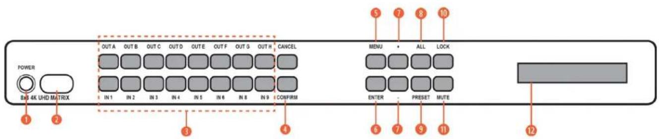
POWER: Press this button to power the unit on (Green LED) or place it into stand-by mode (Red LED).
② IR RECEIVING WINDOW: Accepts IR signals from the included IR remote for control of this unit only.
③ IN 1\~8 & OUT A\~H: Press the "OUT" keys (A\~H) of the outputs you wish to route a source to (they will flash to indicate selection). Next, press the "IN" key of the Input (1\~8) you wish to route to the selected outputs. Finally, press "CONFIRM" to confirm your selection and execute the routing change.
4 CONFIRM: Press this button to confirm newly made input/output routing selections.
CANCEL: Press this button to cancel newly made input/output/preset routing selections before they have been confirmed.
⑤ MENU: Press to enter the LCD menu or to back out from menu items.
6 ENTER: Press to confirm a selection within the LCD menu or to go deeper into a menu item.
7 - / +: Press to move up and down or adjust selections within menus.
⑧ ALL: Press this button to select all outputs simultaneously for routing. Next, press the "IN" key of the input (1\~4) you wish to route to all outputs. Finally, press "CONFIRM" to confirm your selection and execute the routing change.
⑨ PRESET: Press to enter the preset recall menu in the LCD window. Press the "+/-" buttons followed by the "ENTER" button to select and activate the preferred preset.
10 LOCK: Press to lock all button functions on the front panel. Press and hold for 3 seconds to release the lock function. The LCD will display "LOCK" when the function is active.
MUTE: The "MUTE" button functions as a blank audio/video source. To use it, follow the standard matrix routing instructions, but use the "MUTE" button as the input to blank out the selected outputs. When a "MUTE" input is in use it will show up as "M" within the routing display.
⑫ LCD WINDOW: Displays the unit's menu settings and information.
REAR PANEL

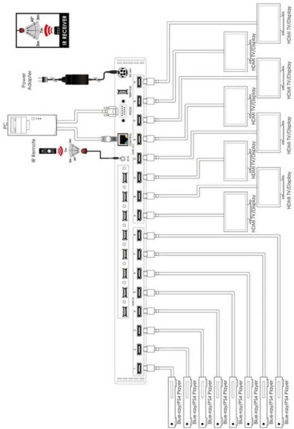
① HDMI IN 1\~8: Connect to the HDMI source equipment such as media players, game consoles or set-top boxes.
② HDMI OUT A\~H: Connect the HDMI outputs to devices such as HDMI TVs, monitors or amplifiers for digital video and audio output. Connect the optical outputs to powered speakers or amplifiers for digital audio output using an appropriate optical cable. The audio from each optical output will be the same as the HDMI output it is paired with.
3 USB POWER OUTPUT 1 \~ 8: Each USB port provides 5V/1A of power intended for use with HDMI over AOC (Active Optical Cables) fiber optic video extension cables.
4 IR IN: Connect to the provided IR Extender to extend the IR control range of the unit. Ensure that the remote being used is within direct line-of-sight of the IR Extender.
5 CONTROL: Connect directly or through a network switch, to your PC/laptop to control the unit via Telnet/WebGUI.
6 RS-232: Connect directly to a PC, laptop or other serial control device to send RS-232 commands to control the unit.
⑦ SERVICE: This slot is reserved for firmware update use only.
8 DC 24V: Plug the 24V DC power adapter into the unit and connect it to an AC wall outlet for power.
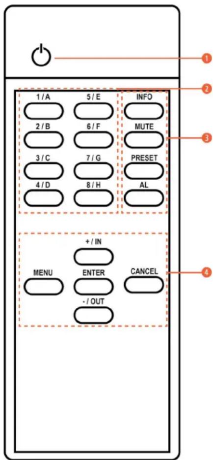
REMOTE CONTROL
① POWER: Press to power the unit on or place it into stand-by mode.
2 1/A \~ 8/H: Press these keys to configure the video routing. Press the "OUT" key followed by the key (A\~H) of the outputs you wish to route a source to (they will flash to indicate selection). Next, press the "IN" key followed by the input (1\~8) you wish to route to the selected outputs. Finally, press "ENTER" to confirm your selection and execute the routing change.
3 ALL: Press this key to select all outputs simultaneously for routing. Next, press the key of the input (1\~4) you wish to route to all outputs. Finally, press "ENTER" to confirm your selection and execute the routing change.
MUTE: Press this key to mute video output. Press the key of the input (1\~4) you wish to route then press mute key to mute video output.
INFO: Switches the information displayed on each output's OSD between the user customized text and the current video/Ethernet details.
PRESET: Press to enter the preset call menu in the LCD window. Press the “+/-” buttons followed by the “ENTER” button to select and activate the preferred preset.
4 A. MENU: Press to enter the LCD menu, or to back out from menu items.
B. ENTER: Press to confirm a selection within the LCD menu or to go deeper into a menu item.
C. CANCEL: Press to cancel newly made input/output/preset routing selections before they have been confirmed.
D. PLUS (+) / IN: Press “+/IN” to navigate up within menus or to begin the selection of an input for routing.
E. MINUS (-) / OUT: Press “-/OUT” to navigate down within menus or to begin the selection of outputs for routing.
HEX CODES
CUSTOM CODE: 8013
POWER: 86 1 / A: 88
CANCEL: 84 2 / B: 8C
ENTER: 9E 3 / C: 90
MENU: D8 4 / D: 85
PLUS / IN: 9D 5 / E: 89
MINUS / OUT: 8F 6 / F: 8D
INFO: 8A 7 / G: 91
MUTE: 8E 8 / H: 95
PRESET: 92
ALL: C6
LCD MENU TREE
| 1ST LEVEL 2ND LEVEL | |
| EDID In1 / In2 / In3 / In 4 / | In All |
| Preset Setup 1/2/3/4 | |
| Network Status Link (Valid) / Mode (Static/DHCP)/ IP/Mask / Gate/MAC | |
| Network Setup Mode: (Static/DHCP) | |
| Static: IP/Mask/Gate | |
| Firmware Version | |
| Firmware Update USB update | |
| Factory Reset Factory reset | |
RS-232 PROTOCOL
| MATRIX REMOTE CONTROLL | |||
| Pin Assignment | Pin Assignment | ||
| 1 NC 1 NC | |||
| 2 | Tx | 2 | |
| 3 | Rx | 3 | |
| 4 NC 4 NC | |||
| 5 | GND | 5 | |
| 6 NC 6 NC | |||
| 7 NC 7 NC | |||
| 8 NC 8 NC | |||
| 9 NC 9 NC | |||
Baud Rate: 19200bps
Data Bit: 8 bits
Parity: None
Flow Control: None
Stop Bit: 1
RS-232 & TELNET COMMANDS
| COMMAND DESCRIPTION | DESCRIPTION OF PARAMETER | |
| ? | Print all available RS-232/Telnet commands to the screen | NONE |
| GET FW VER Print Firmware version to the screen NONE | ||
| COMMAND VER | Print command version to the screen | NONE |
| GET MAC ADDR Print MAC address to the screen NONE | ||
| GET MODEL NAME Print Model Name to the screen NONE | ||
| GET MODEL TYPE N | Print Model Name to the screen | n: 1=matrix, 2=scaler, 3=splitter, 4=repeater |
| SET FACTORY DEFAULT Reset unit to factory default NONE | ||
| SET FACTORY IPCONFIG DEFAULT | IP configuration was reset to factory defaults (DHCP) | NONE |
| SET FACTORY OUT ROUTE DEFAULT | IP configuration was reset to factory defaults (DHCP) | NONE |
| SET POWER B Power unit ON/OFF b = ON, OFF | ||
| SET POWER N | Power unit ON/OFF n = 0 - 1 (0-OFF, 1-ON) | |
| SET POWER STANDBY | Power unit Standby | b = ON, OFF, STANDBY |
| GET POWER | Print power unit ON/OFF/Standby to the screen | b = ON, OFF, STANDBY |
| SET UART N1 BAUDRATE N2 | Set RS-232 baud rate | n1 = 1,2,3...n2 = 4800, 9600, 19200, 38400, 57600 or 115200 |
| GET UART N BAUDRATE | Print RS-232 baud rate to the screen | n = 4800, 9600, 19200, 38400, 57600 or 115200 |
| SET IP MODE N | n = 0-Static IP, 1-DHCP mode | NONE |
| GET IP MODE | Print IP mode status to the screen | s = static, dhcp, force ip |
| GET IPCONFIG | Print the current running IP config to the screen | NONE |
| SET IPADDR N.N.N.N | Set the IP address | N.N.N.N. |
| GET IPADDR N.N.N.N | Print the IP address to the screen | NONE |
| SET NETMASK N.N.N.N | Set the NETMASK address | n = 0~255 |
| GET NETMASK | Print the NETMASK to the screen | NONE |
| SET GETEWAY N.N.N.N | Set the GATEWAY address | n = 0~255 |
| GET GATEWAY | Print the GATEWAY to the screen | NONE |
| GET TELNET MAXIMUM USER N | Print Telnet login status to the screen | n = 0,1,2,3,4... |
| SET WEBGUI USERNAME S | Set WebGUI username | {s} = name string |
| GET WEBGUI USERNAME | Print WebGUI username to the screen | NONE |
| SET WEBGUI PASSWORD S | Set WebGUI password | {s} = password string |
| GET WEBGUI PASSWORD | Print WebGUI password to the screen | NONE |
| SET WEBGUI LOGIN B | Enable or disable WebGUI login | b = ON, OFF (OFF-DISABLED, ON-ENABLED) |
| GET WEBGUI LOGIN | Print WebGUI login status to the screen | NONE |
| SET TELNET USERNAME S Set Telnet username s = name string | ||
| GET TELNET USERNAME Print Telnet username to the screen NONE | ||
| SET TELNET PASSWORD S Set Telnet password s = password string | ||
| GET TELNET PASSWORD Print Telnet password to the screen NONE | ||
| SET TELNET PORT N Set Telnet port number n = 23,... (Telnet port number) | ||
| GET TELNET PORT N Set Telnet port number {s} = password string | ||
| GET HOSTENAME N Print Hostname to the screen {s} = name string | ||
| SET WEBGUI LOGIN TIMEOUT N | Set WebGUI login timeout | n = 1,2,3,4...Seconds |
| ROSDINFO | Get OSD information status | NONE |
| USBPWR | USB Power ON/OFF | USBPWR P1 P2P1 = Output Port (1~4) / P2 = Action (ON/OFF) |
| SET IN N NAME S | Name an input source n = 1,2,3...8 | |
| GET IN N NAME | Print the input name to the screen | n = 1,2,3...8 |
| SET OUT X NAME S | Name an output sync monitor | x = a,b,c...h / s = name string name / size: 32 Byte |
| GET OUT X NAME | Print the output name to the screen x = a,b,c ...h | |
| SET OUT X ROUTE N | Set output routing | x = a,b,c,d,e...h / n = 1,2,3,4,5...8 |
| GET IN NAME LIST | Print all input name to the screen | NONE |
| GET OUT NAME LIST | Print all output name to the screen | NONE |
| SET OUT X 4K2K DOWNSCALE MODE N | Config output x 4K2K downscale mode for sync monitor | x = a,b,c...h / n = 0-passthrough, 1-auto, 2-1080p |
| GET OUT X HDCP 4K2K DOWNSCALE MODE N | Print output x 4K2K downscale mode to the screen | x = a,b,c...h / n = 0-passthrough, 1-auto, 2-1080p |
| GET IN N1 HACTIVE N2 | Print input H active to the screen | n1 = 1,2,3...8 / n2 = 640, 800, 1024 |
| GET IN N1 VACTIVE N2 | Print input V active to the screen | n1 = 1,2,3...8 / n2 = 480, 768, 600 |
| GET IN N1 REFRESH RATE | Print input refresh rate to the screen | n1 = 1,2,3...8 / n2 = 5994, 6000, 7500, 8503 |
| GET IN N1 INTERLACE | Print input interlace to the screen | n1 = 1,2,3...8 / n2 = 0-none interlace, 1-interlace |
| GET IN N1 SYNC STATUS | Print input sync status to the screen | n1 = 1,2,3...8 / n2 = 0-no sync, 1-sync active |
| GET IN N1 TIMING | Print input n Timing | n = 0,1,2,3,4,5...8(0-native, 1-800x600, 2-1024x768,...) |
| SET IR IN CHANNEL N | Set IR in channel information | n = 0,1,2,3...15 |
| GET IR IN CHANNEL N | Get IR in channel information | n = 0,1,2,3...15 |
| SET IR IN CUSTOM CODE 0XH | Set IR in custom code | data: 0x0000~0x7fff |
| GET IR IN CUSTOM CODE | Get IR in custom code | data: 0x0000~0x7fff |
| SET FAN CONTROL MODEL N | Print fan speed | n: 0=always ON, 1=follow temperature |
| GET FAN CONTROL MODE | Print fan speed | n: 0=always ON, 1=follow temperature |
| GET FAN N1 SPEED | Print fan speed | n1 = 1,2 / n2 = 0,1,2,... |
| GET DEVICE TEMPERATURE N | Print machine temperature | n = 0,1,2,3... |
| SET USB X POWER SUPPLY B | Set machine usb power supply mode to ON/OFF | x = a,b,c...h / b = ON, OFF |
| GET USB X POWER SUPPLY | Print machine usb power supply mode | x = a,b,c...h / b = ON, OFF |
| SET OUT ROUTE XN-NN | Routing command for all OUTPUT Group | xn-nn: a1 (a=1), b2 (b=2), c3 (c=3)... |
| SET ALL OUT ROUTE N Routing command for all OUTPUT n = 1,2,3,4,5...8 | ||
| GET ALL OUT ROUTE | Prints current routing status to the screen | NONE |
| SET KEYLOCK B Lock or unlock keypad b = ON, OFF (OFF-UNLOCKED, ON-LOCKED) | ||
| GET KEYLOCK | Print Lock or Unlock keypad to the screen | NONE |
| SET CURRENT ROUTE TO PRESET N | Save the current routing state to a preset (Video/Audio routing state depends on different devices. Please add other commands for key features if required.) | n = 1,2,3,...8 |
| SET ROUTE PRESET N Load a routing state from preset n = 1,2,3,...8 | ||
| GET ROUTE PRESET N | Print a routing state preset to the screen | n = 1,2,3,...8 |
| SET ROUTE PRESET N NAME S Set a routing preset name n = 1,2,3,...8 | ||
| GET ROUTE PRESET N NAME Get a routing preset name n = 1,2,3,...8 | ||
| GET IN PORT NUMBER | Print total input port number to the screen | NONE |
| GET IN PORT NUMBER | Print total input port number to the screen | NONE |
| GET OUT PORT NUMBER | Print total output port number to the screen | NONE |
| GET OUT X SYNC STATUS | Print the output link status to the screen | x = a,b,c ...h |
| SET OUT X MASK B MASK OUTPUT(S) | x = a,b,c ...hb = ON, OFF (OFF=unmask, ON=mask) | |
| GET OUT X MASK N | MASK OUTPUT(S) x = a,b,c ...h | |
| SET OUT X OSD TRANSPARENCY LEVEL N | Set OUTPUT OSD transparency | x = a,b,c,d,e...h / n = 1-8 |
| GET OUT X OSD TRANSPARENCY LEVEL N | Print output sync OSD transparency to the screen | x = a,b,c,d,e...h / n = 1-8 |
| SET OUT X OSD B | Set output [x] osd enable/disable | x = a,b,c...h / b = ON, OFF |
| GET OUT X OSD | Print output [x] osd enable/disable to the screen | x = a,b,c...h / b = ON, OFF |
| SET OUT X BANNER TEXT S | Set output information banner (OSD text) display text value | x = a,b,c...h / s = string |
| GET OUT X BANNER TEXT | Get output osd text (Information banner) display text value | x = a,b,c...h / s = string |
| SET OUT X BANNER FONT SIZE N | Change OSD text size | x = a,b,c...h / n = 1,2,3 |
| GET OUT X BANNER FONT SIZE N | Query OSD text size | x = a,b,c...h / n = 1,2,3 |
| SET OUT X BANNER FONT COLOR S | Change OSD text color | x = a,b,c...h / s = black, white, red, green, blue, magenta, yellow, cyan, gray |
| GET OUT X BANNER FONT COLOR S | Query OSD text color | x = a,b,c...h / s = black, white, red, green, blue, magenta, yellow, cyan, gray |
| GET OUT BANNER FONT COLOR LIST S | Query OSD text color list value | s = black, white, red, green, blue, magenta, yellow, cyan, gray |
| SET OUT X OSD BACKGROUND COLOR S | Change OSD text color | x = a,b,c...h / s = black, blue, green, cyan, red, magenta, yellow, white... |
| GET OUT X OSD BACKGROUND COLOR S | Change OSD background color | x = a,b,c...h / s = black, blue, green, cyan, red, magenta, yellow, white... |
| GET OUT OSD BACKGROUND COLOR LIST S | Query OSD background color list value | s = black, blue, green, cyan, red, magenta, yellow, white... |
| SET IN N1 EDID N2 EDID TABLE SELECT | n1 = 1,2,3,4...8n2 = 1,2,3...22 (1-INT1, 2-INT2...,7-USER1, 8-USESR2...,15-Sink A, 16-Sink B)Total User EDID number equal to Input source number.Total Sink EDID number equal to output number of device. | |
| GET IN N1 EDID N2 Input EDID table query | n1 = 1,2,3,4...8n2 = 1,2,3...22 (1-INT1, 2-INT2...,7-USER1, 8-USESR2...,15-Sink A, 16-Sink B)Total User EDID number equal to Input source number.Total Sink EDID number equal to output number of device. | |
| GET IN EDID LIST NN Input EDID table list query | nn = 1,2,3...22 (1-INT1, 2-INT2...,7-USER1, 8-USESR2...,15-Sink A, 16-Sink B)Total User EDID number equal to Input source number.Total Sink EDID number equal to output number of device. | |
| SET EDID N NAME S EDID TABLE SELECT | n = 7,8,9,...14 (only USER EDID name can be edited) / s = string / name size: 32 Byte | |
| GET EDID N NAME S EDID TABLE SELECT | n = 7,8,9,...14 (only USER EDID name can be edited) / s = string / name size: 32 Byte | |
| SET USER N EDID DATA H,H,H...... Upload EDID | n = 1,2,3,4...8 (1- USER1, 2-USER2...) h = EDID data | |
| GET USER N EDID DATA Download User n EDID n = 1,2,3,4...8 (1-INT1, 2-INT2...) / h = EDID data | ||
| GET SINK X EDID DATA Download SINK [x] EDID x = A,B,C...h / h = EDID data | ||
| GET IN N EDID DATA | Download Input n EDID | n = 1,2,3...8h = EDID data (1-INT1, 2-INT2...,7-USER1, 8-USESR2...,15-Sink A, 16-Sink B)Total User EDID number equal to Input source number.Total Sink EDID number equal to output number of device. |
| GET ALL IN EDID LIST | Print EDID list | n1 = 1,2,3,4...8n2 = 1,2,3...22 (1-INT1, 2-INT2...,7-USER1, 8-USESR2...,15-Sink A, 16-Sink B)Total User EDID number equal to Input source number.Total Sink EDID number equal to output number of device. |
| GET INTERNAL N EDID DATA | Download EDID | n = 1,2,3,4...6 (1-INT1, 2- INT2...) / h = EDID data |
| SET ALL IN EDID MODE B | Set EDID mode to “all” or “appoint” | b = ON, OFF (all or appoint) |
| GET ALL IN EDID MODE B | Print EDID mode to “all” or “appoint” | b = ON, OFF (all or appoint) |
| SET ALL IN EDID N | Set select EDID to all input | n = 1,2,3... 22 (1-INT1, 2-INT2...,7-USER1,8-USESR2...,15-Sink A, 16-Sink B)Total User EDID number equal to Input source number.Total Sink EDID number equal to output number of device. |
| GET ALL IN EDID N | Print “all EDID mode” select EDID | n = 1,2,3... 22 (1-INT1, 2-INT2...,7-USER1,8-USESR2...,15-Sink A, 16-Sink B)Total User EDID number equal to Input source number.Total Sink EDID number equal to output number of device. |
| SET IN N1 HDCP MODE N2 Set input [x] | HDCP mode | n1 = 1,2,3...8 / n2 = 0,1,2 (0-disable, 1-follow source, 2-follow display) |
| GET IN N HDCP MODE N2 | Print input [n] HDCP status to the screen | n= 1,2,3...8 / n2 = 0,1,2 (0-disable, 1- follow source, 2-follow display) |
| GET IN N HDCP STATUS | Print input HDCP status to the screen | n1 = 1,2,3...8 / n2 = 0,1,2,3 (0-OFF, 1-HDCP1.x,2-HDCP2.2) |
| GET OUT X HDCP STATUS | Print input HDCP status to the screen | x = a,b,c...h / n2 = 0,1,2,3 (0-OFF, 1-HDCP1.x,2-HDCP2.2, 3-HDCP1.x failed, 4-HDCP2.x failed) |
| GET OUT X HDCP STATUS | Print input HDCP status to the screen | x = a,b,c...h / n2 = 0,1,2,3 (0-OFF, 1-HDCP1.x,2-HDCP2.2, 3-HDCP1.x failed, 4-HDCP2.x failed) |
| GET OUT X HDCP ABILITY N | Print output [x] sink HDCP ability to the screen | x = a,b,c...h / n2 = 0,1,2 (0-None HDCP,1-HDCP1.x, 2-HDCP2.2) |
| GET IN X HDCP ABILITY N | Print input n source HDCP ability to the screen | n2 = 0,1,2,3 (0-None HDCP, 1-HDCP1.x,2-HDCP2.2, 3-HDCP1.4+2.2) |
| SET PATTERN X MODE B Set pattern mode on, off x = a,b,c,d,e...h / b = on, off | ||
| GET PATTERN X MODE B Get pattern mode on, off x = a,b,c,d,e...h / b = on, off | ||
| SET PATTERN X TIMING N Set pattern output timing | x = a,b,c...h (HDMI out, HDBT out, LR out...)n = 1~41,401~435,501~506... | |
| GET PATTERN X TIMING N Get pattern output timing | x = a,b,c...h (HDMI LR out...) / n = out, HDBT out, 1~41,401~435, 501~506,... | |
| GET PATTERN TIMING LIST Get support pattern output timing list | Please refer "timing code" table for detail timing value definitions. | |
| SET PATTERN X TYPE N Set pattern output type | x = a,b,c,d,e...h / n = 1: black, 2: white, 3: red, 4: green, 5: blue, 6: magenta, 7: yellow, 8: cyan, 9: gray | |
| SET PATTERN X TYPE N Get pattern output type | x = a,b,c,d,e...h / n = 1: black, 2: white, 3: red, 4: green, 5: blue, 6: magenta, 7: yellow, 8: cyan, 9: gray | |
| SET OUT X1 OSD INFO DISPLAY B1 EXAMPLE: SET OUT B OSD INFO DISPLAY OFF | set out x1 osd info display b1 x1 = a,b,c,d,e...b1 = on, off | Enable or disable the info OSD for the specified output. |
| After each successful cross point command, the Input and Output resolution will display for 5 seconds in the upper left corner of the Output channel. You can disable/enable this feature via the front panel buttons or RS-232/Telnet.VIA FRONT PANEL BUTTONMENU ->SYSTEM SETUP ->SHOW TIMING INFO ->SELECT OUTPUT A~HPress the desired Output channel you wish to change by cycling through ON and OFF for each OUTPUT.N= OSD IS DISABLEDY= OSD IS ENABLED.ENTER -> | ||
TELNET CONTROL
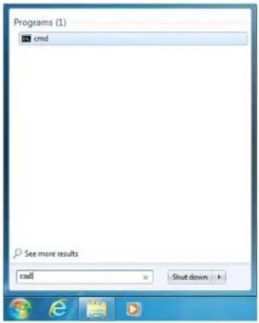
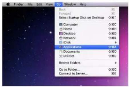
Before attempting to use the Telnet control, please ensure that both the Matrix (via the 'LAN /CONTROL' port) and the PC/Laptop are connected to the same active networks. To access the Telnet control in Windows 7, click on the 'Start' menu and type "cmd" in the search field then press ENTER. Under Mac OS X, go to Go→Applications→Utilities→Terminal. See below for reference.
Once in the command line interface (CLI) type "Telnet", then the IP address of the unit and "23", then hit ENTER.
Microsoft Windows [Version 6.1.7601]
Copyright (c) 2009 Microsoft Corporation. All rights reserved.
C:\Users\Administrator>telnet 192.168.XX.XX 23
This will bring us into the unit which we wish to control. Type "help" to list the available commands.
NOTE: Commands will not be executed unless followed by a carriage return. Commands ARE case-sensitive. If the IP is changed then the IP Address is required for Telnet access will also change accordingly.
WEBGUI CONTROL
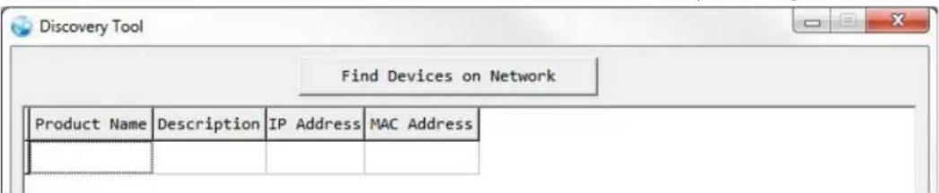
Install the IP Discovery Tool:
- Please obtain the Device Discovery software and save it in a directory where you can easily find it.
NOTE: The unit's default IP address is 192.168.1.50
- Connect the unit and your PC/Laptop to the same active network and execute the Device Discovery software. Click on "Find Devices on Network" and a list of devices connected to the local network will show up indicating their current IP address.
-
By clicking on one of the listed devices you will be presented with the network details of that particular device. If you choose, you can alter the static IP network settings for the device or switch the unit into DHCP mode to automatically obtain proper network settings from a local DHCP server. To switch to DHCP mode, please select DHCP from the IP mode drop-down, then click "Save" followed by "Reboot".
-
Once you are satisfied with the network settings, you may use them to connect via Telnet or WebGUI. The network information window provides a convenient link to launch the WebGUI directly.
- Login to the WebGUI:

-
By default, both the Username and Password are "admin" for the WebGUI. The administrator password can be changed within the "System Settings" tab of the WebGUI if desired.
-
The following function tabs will always display on left side of the WebGUI to aid with navigation.
This page provides video routing settings, preset saving/loading, and Pattern timing/color control settings.
- Video Routing: To begin assigning a new video route, please click the button of the HDMI output you wish to send video to and then click on the button of the preferred HDMI input port. If desired, you may select more than one output prior to selecting the input. As you select each button they will change their color to orange. The new route will become active immediately after selecting the input port and the routing information displayed on the buttons will change accordingly.
- Output and Input Naming: All inputs and outputs can be renamed as required. To rename the input and output ports please click the "edit" icon (☑). Click the "Save" button to confirm the change. NOTE: Blank spaces are not allowed in names.
- Output Video Mute: Each output can be individually muted (black video, no audio). To mute an output, please turn on the icon.
- Pattern Timing: This Pattern timing tab provides multiple timing for HDMI output, The supports timing are list below: 4K2K25\~4K2K60 and 1080p60/1080p50 and 720p60/720p50.
- Pattern Color Control: The section allows for set the pattern color.
- DownScaling: The section allows for adjust from 4K2K to 1080 resolutions.
- OSD Text: The section allows the user to enable and disable the OSD Text functions. If enabled, the OSD Text function allows text entered in "OSD Text" to be displayed in the upper right corner of the window. The text length is limited to 64 characters.
- OSD Text Settings: Each output can display (1) line of customized OSD text. The text can be customized in content, background color, size and position. Click the "edit" icon (☑) associated with each output to modify these settings. Please click the "Save" button after making changes to the positioning or content. All other changes occur as soon as they are made.
- Set Input Name: To rename the input port, type the new name in the space provided in the Edit window. Click the "Save" button to confirm the change.
NOTE: Blank spaces (“”) are not allowed in names.
- HDCP: There are (3) HDCP source behavior options available: HDCP Support Off, Refer to Source and Refer to Display. HDCP Support Off completely disables support for HDCP on that input. Refer to Source makes the input port support the same HDCP version as required by the connected source. Refer to Display makes the input support the HDCP version of the currently routed display.
- Preset Setting
This matrix can store up to (8) video routing presets. Presets can be utilized to store multiple different routing states in advance for rapid, hassle-free, recall.
- Store: Once you have the matrix set the way you like, you can click the "Preset Set" icon ( ) in the upper right corner of the window and the Preset Set window will open. You may also name the preset at this stage by selecting the "edit" icon ( ). Click the main part of the Preset's button to store the current state into that preset.
- Recall: When you wish to load a previously stored preset, please click the "Preset Recall" icon (☐) and you will be presented with a choice of the available (8) presets. Hovering the mouse over each button will display the preset routes stored within it. The preset will load immediately upon selecting the preset.
EDID SETTINGS
This matrix provides the option of (6) standard EDIDs, (8) sink sourced EDIDs and (8) customer uploaded EDIDs that can be assigned to each input port individually. The names of the (8) customer uploaded EDIDs can changed if desired.
- Customer EDID Settings: To upload a custom EDID, please click the "Upload" button next to the Customer EDID Settings item you would like to change. An EDID Upload window will appear, allowing you to locate and upload your preferred EDID file from the file directory on your local PC. Once the correct file has been selected, please click the "Upload" button in the window, and the file will be transferred to the matrix.
- Sink EDID Download: To save an existing custom EDID to your local PC please press the "Download" button next to the Customer EDID Settings item you would like to save. Depending on your browser settings you will either be asked where to save the downloaded file or the file will be transferred to the default download location on your PC.
- Set EDID Input Content: The Set EDID Input Content section allows for the assignment of an EDID to each individual input port, or to all inputs at once. Click on an input to open the EDID Source management window. Multiple inputs can be selected at once, if desired. Select the new EDID source to use and the change will occur immediately.
NOTE: This matrix comes with the following (6) default EDIDs:
- FHD/2CH: 1080p@60Hz (148MHz), LPCM 2.0, 8-bit color.
- FHD/MCH: 1080p@60Hz (148MHz), LPCM 7.1 & bitstream, 8-bit color.
- 4K UHD/2CH: 3840x2160p@30Hz (297MHz), LPCM 2.0, Deep Color (8/10/12-bit)
- 4K UHD / MCH: 3840x2160p@30Hz (297MHz), LPCM 7.1 & bitstream, Deep Color (8/10/12-bit).
- 4K UHD+ / 2CH: 3840x2160p@60Hz (594MHz), LPCM 2.0, Deep Color (8/10/12-bit).
- 4K UHD+ / MCH: 3840x2160p@60Hz (594MHz), LPCM 7.1 & bitstream, Deep Color (8/10/12-bit).
NOTE: In some rare cases it is possible for custom or external EDIDs to cause compatibility issues with certain sources. If this happens, it is recommended to switch to one of the (6) default EDIDs for maximum compatibility.
DEVICE SETTING
- This page provides device settings options including turning the USB power supply ON/OFF, changing the IR Channel and IR discrete custom code, Displays the unit's temperature and current state of (2) external fans including individual fan RPM. The fan control default setting is always on.
USER CONFIG
- This tab provides User Configuration options including changing the username and password for both of Administrator and General user.
SYSTEM SETTING
- This page provides system configuration options including turning the unit's power ON/OFF, changing the network settings, downloading/restoring saved system configurations and updating the firmware.
ADMIN LOG OUT
Video Switch
Edid Settings
Device Settings
User Config
System Settings
Admin - Logout
Clicking the "Logout" tab will automatically log the user out of the WebGUI and return to login page.
flowchart
graph TD
    A["Blue-ray/PS4 Player"] --> B["1"]
    C["Blue-ray/PS4 Player"] --> D["2"]
    E["Blue-ray/PS4 Player"] --> F["3"]
    G["Blue-ray/PS4 Player"] --> H["4"]
    I["Blue-ray/PS4 Player"] --> J["5"]
    K["Blue-ray/PS4 Player"] --> L["6"]
    M["Blue-ray/PS4 Player"] --> N["7"]
    O["Blue-ray/PS4 Player"] --> P["8"]
    Q["Blue-ray/PS4 Player"] --> R["9"]
    S["Blue-ray/PS4 Player"] --> T["10"]
    U["Blue-ray/PS4 Player"] --> V["11"]
    W["Blue-ray/PS4 Player"] --> X["12"]
    Y["Control"] --> Z["PC"]
    AA["RE232"] --> AB["PC"]
    AC["SERVICE"] --> AD["PC"]
    AE["DC 24V"] --> AF["PC"]
    AG["HDMI TV/Display"] --> AH["1"]
    AI["HDMI TV/Display"] --> AJ["2"]
    AK["HDMI TV/Display"] --> AL["3"]
    AM["HDMI TV/Display"] --> AN["4"]
    AO["HDMI TV/Display"] --> AP["5"]
    AQ["HDMI TV/Display"] --> AR["6"]
    AS["HDMI TV/Display"] --> AT["7"]
    AU["HDMI TV/Display"] --> AV["8"]
    AW["HDMI TV/Display"] --> AX["9"]
    AY["HDMI OUT"] --> AZ["10"]
    BA["IR Remote"] --> BB["7m"]
    BC["Power Adapter"] --> BD["3m 7m 3m IR RECEIVER"]
SUPPORT TIMING
| RESOLUTION INPUT OUTPUT | ||
| 640x480@60/72/75/85 | √ | √ |
| 720x400@85 | √ | √ |
| 720x480p@59.94/60 | √ | √ |
| 720x576p@50 | √ | √ |
| 800x600@56/60/72/75/85 | √ | √ |
| 1024x768@60/70/75/85 | √ | √ |
| 1152x864@75 | √ | √ |
| 1280x720p@50/59.94/60 | √ | √ |
| 1280x768@60/75 | √ | √ |
| 1280x800@60RB/60 | √ | √ |
| 1280x960@60 | √ | √ |
| 1280x1024@60 | √ | √ |
| 1360x768@60 | √ | √ |
| 1366x768@60 | √ | √ |
| 1440x480i@59.94/60 | √ | √ |
| 1440x576i@50 | √ | √ |
| 1400x1050@60RB/60 | √ | √ |
| 1440x900@60RB/60 | √ | √ |
| 1600x900@60 | √ | √ |
| 1600x1200@60 | √ | √ |
| 1680x1050@60RB/60 | √ | √ |
| 1920x1080@60RB | √ | √ |
| 1920x1080i@60 | √ | √ |
| 1920x1080p@23.97/24/25/29.97/30/59.94/60 | √ | √ |
| 3840x2160p@24/25/30 | √ | √ |
| 3840x2160@50/60(4:4:4)/50/60(4:2:0) | √ | √ |
| 4096x2160p@24 | √ | √ |
HDMI CABLE LENGTH
| TIMING INPUT OUTPUT | ||
| 1080p ~33ft/10M ~33ft/10M | ||
| 4K2K@30 ~33ft/10M ~33ft/10M | ||
| 4K2K@60 (certified HDMI cable) ~10/3M ~33ft/10M |
IR CABLE PIN ASSIGNMENT

PLEASE READ THE FOLLOWING TERMS AND CONDITIONS CAREFULLY BEFORE USING THIS HARDWARE, COMPONENTS AND SOFTWARE PROVIDED BY, THROUGH OR UNDER A-NeuVideo, INC (COLLECTIVELY, THE "PRODUCT"). By using installing or using the Product, you unconditionally signify your agreement to these Terms and Conditions. If you do not agree to these Terms and Conditions, do not use the Product and return the Product to A-NeuVideo, Inc. at the return address set forth on the Product's packing label at your expense. A-NeuVideo, Inc. may modify these Terms and Conditions at anytime, without notice to you.
RESTRICTIONS ON USE OF THE PRODUCT
It is your responsibility to read and understand the installation and operation instructions, both verbal and in writing, provided to you with respect to the Product. You are authorized to use the Product solely in connection with such instructions. Any use of the Product not in accordance with such instructions shall void any warranty pertaining to the Product. Any and all damages that may occur in the use of the Product that is not strictly in accordance with such instructions shall be borne by you and you agree to indemnify and hold harmless A-NeuVideo, Inc. from and against any such damage.
The Product is protected by certain intellectual property rights owned by or licensed to A-NeuVideo. Any intellectual property rights pertaining to the Product are licensed to you by A-NeuVideo, Inc. and/or its affiliates, including any manufacturers or distributors of the Product (collectively, "A-NeuVideo") for your personal use only, provided that you do not change or delete any proprietary notices that may be provided with respect to the Product.
The Product is sold to you and any use of any associated intellectual property is deemed to be licensed to you by A-NeuVideo for your personal use only. A-NeuVideo does not transfer either the title or the intellectual property rights to the Product and A-NeuVideo retains full and complete title to the intellectual property rights therein. All trademarks and logos are owned by A-NeuVideo or its licensors and providers of the Product, and you may not copy or use them in any manner without the prior written consent of A-NeuVideo, which consent may be withheld at the sole discretion of A-NeuVideo.
The functionality and usability of the Product is controlled by A-NeuVideo, Inc. from its offices within the State of Texas, United States of America. A-NeuVideo makes no representation that materials pertaining to the Product are appropriate or available for use in other locations other than the shipping address you provided with respect thereto. You are advised that the Product may be subject to U.S. export controls.
DISCLAIMERS AND LIMITATION OF LIABILITY
A-NeuVideo may change or modify the Product at any time, from time to time.
THE PRODUCT IS PROVIDED "AS IS" AND WITHOUT WARRANTIES OF ANY KIND EITHER EXPRESS OR IMPLIED. A-NEUVIDEO DOES NOT WARRANT OR MAKE ANY REPRESENTATIONS REGARDING THE USE OR THE RESULTS OF THE USE OF THE PRODUCT'S CORRECTNESS, ACCURACY, RELIABILITY, OR OTHERWISE.
A-NeuVideo has no duty or policy to update any information or statements pertaining to the Product and, therefore, such information or statements should not be relied upon as being current as of the date you use the Product. Moreover, any portion of the materials pertaining to the Product may include technical inaccuracies or typographical errors. Changes may be made from time to time without notice with respect to the Product.
TO THE FULLEST EXTENT PERMISSIBLE PURSUANT TO APPLICABLE LAW, A-NEUVIDEO DISCLAIMS ALL WARRANTIES, EXPRESS OR IMPLIED, INCLUDING, BUT NOT LIMITED TO IMPLIED WARRANTIES OF MERCHANTABILITY, FITNESS FOR A PARTICULAR PURPOSE AND NON-INFRINGEMENT. A-NEUVIDEO DOES NOT WARRANT THE ACCURACY, COMPLETENESS OR USEFULNESS OF ANY INFORMATION WITH RESPECT TO THE PRODUCT. A-NEUVIDEO DOES NOT WARRANT THAT THE FUNCTIONS PERTAINING TO THE PRODUCT WILL BE ERROR-FREE, THAT DEFECTS WITH RESPECT TO THE PRODUCT WILL BE CORRECTED, OR THAT THE MATERIALS PERTAINING THERETO ARE FREE OF DEFECTS OR OTHER HARMFUL COMPONENTS. A-NEUVIDEO WILL USE ITS REASONABLE EFFORTS TO CORRECT ANY DEFECTS IN THE PRODUCT UPON TIMELY WRITTEN NOTICE FROM YOU NOT TO EXCEED 10 BUSINESS DAYS AFTER RECEIPT BY YOU OF THE PRODUCT, BUT YOU (AND NOT A-NEUVIDEO) ASSUME THE ENTIRE COST OF ALL NECESSARY SERVICING, REPAIR AND CORRECTION THAT WAS CAUSED BY YOU UNLESS OTHERWISE AGREED TO IN A SEPARATE WRITING BY A-NEUVIDEO.
UNDER NO CIRCUMSTANCES, INCLUDING, BUT NOT LIMITED TO, NEGLIGENCE, SHALL A-NEUVIDEO BE LIABLE FOR ANY SPECIAL OR CONSEQUENTIAL DAMAGES THAT RESULT FROM THE USE OF, OR THE INABILITY TO USE THE PRODUCT IN ACCORDANCE WITH ITS SPECIFICATIONS, EVEN IF A-NEUVIDEO OR ITS REPRESENTATIVES HAVE BEEN ADVISED OF THE POSSIBILITY OF SUCH DAMAGES. IN NO EVENT SHALL A-NEUVIDEO'S TOTAL LIABILITY TO YOU FROM ALL DAMAGES, LOSSES, AND CAUSES OF ACTION (WHETHER IN CONTRACT, OR OTHERWISE) EXCEED THE AMOUNT YOU PAID TO A-NEUVIDEO, IF ANY, FOR THE PRODUCT.
- SAFETY INFORMATION
- CONTENTS
- INTRODUCTION
- SYSTEM REQUIREMENTS
- SAFETY PRECAUTIONS
- DISCLAIMERS
- COPYRIGHT NOTICE
- TRADEMARK ACKNOWLEDGMENTS
- FEATURES
- SPECIFICATIONS
- FRONT PANEL
- REAR PANEL
- REMOTE CONTROL
- HEX CODES
- TELNET CONTROL
- WEBGUI CONTROL
- Install the IP Discovery Tool:
- - Login to the WebGUI:
- - Preset Setting
- EDID SETTINGS
- DEVICE SETTING
- USER CONFIG
- SYSTEM SETTING
- ADMIN LOG OUT
- RESTRICTIONS ON USE OF THE PRODUCT
- DISCLAIMERS AND LIMITATION OF LIABILITY
Brand : A-NeuVideo
Model : ANI-88HDRH
Category : Router